

Page 1
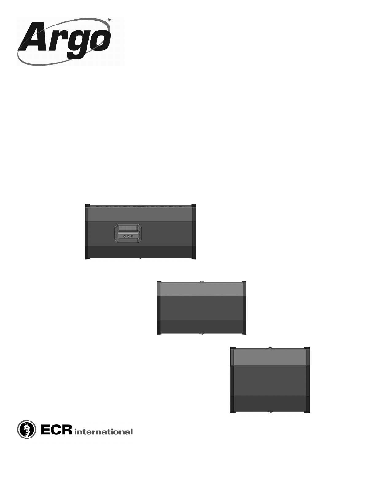
Models
UNIVERSAL CONTROL SERIES
UZ3, UZ4, UZ6
Universal Control
EZ3, EZ1
Expansion Module
UZ3, UZ4, UZ6
INSTALLATION, OPERATION &
MAINTENANCE MANUAL
EZ3
EZ1
Manufactured by:
ECR International Inc.
2201 Dwyer Avenue, Utica, NY 13501
Tel. 800 253 7900
www.ecrinternational.com
PN 240010923 REV. F [07/01/2018]
Page 2
TABLE OF CONTENTS
1 - Important Safety Information ...................................................................................... 2
2 - Product Description And Features.................................................................................3
3 - Mounting .................................................................................................................4
4(OHFWULFDO6SHFL¿FDWLRQV'LPHQVLRQV$QG:LULQJ&RQQHFWLRQV........................................... 5
5 - User Interface ......................................................................................................... 12
6&RQWURO&RQ¿JXUDWLRQ ............................................................................................... 13
7 - Sequence Of Operation ............................................................................................. 15
8 - Troubleshooting .................................................................................................. 19-20
9 - Replacement Parts ................................................................................................... 20
10 - Technical Support .................................................................................................. 20
1 - IMPORTANT SAFETY INFORMATION
Become familiar with symbols identifying
potential hazards.
This is the safety alert symbol. Symbol alerts you to
potential personal injury hazards. Obey all safety messages
following this symbol to avoid possible injury or death.
!
DANGER
Indicates a hazardous situation which, if not avoided,
:,//UHVXOWLQGHDWKRUVHULRXVLQMXU\
!
WARNING
Indicates a hazardous situation which, if not avoided,
could result in death or serious injury.
!
CAUTION
Indicates a hazardous situation which, if not avoided,
could result in minor or moderate injury.
General
,QVWDOODWLRQVKDOOEHFRPSOHWHGE\TXDOL¿HGDJHQF\
WARNING
!
Fire, explosion, asphyxiation and electrical shock
hazard. Improper installation could result in death
or serious injury. Read this manual and understand
all requirements before beginning installation.
NOTICE
Used to address practices not related to personal
injury.
,QIRUPDWLRQDQGVSHFL¿FDWLRQVRXWOLQHGLQWKLVPDQXDOLQHϑHFWDWWKHWLPHRISULQWLQJRIWKLVPDQXDO(&5,QWHUQDWLRQDO,QF
UHVHUYHVWKHULJKWWRGLVFRQWLQXHFKDQJHVSHFL¿FDWLRQVRUV\VWHPGHVLJQDWDQ\WLPHZLWKRXWQRWLFHDQGZLWKRXWLQFXUULQJDQ\
REOLJDWLRQZKDWVRHYHU
2
PN 240010923 Rev. F [07/01/2018]
Page 3

2 - PRODUCT DESCRIPTION AND FEATURES
Product Description
7KH$UJR8QLYHUVDO&RQWUROSURYLGHVLQGLYLGXDOFRQWUROIRU
comfort heating, domestic hot water along with many other
residential hot water applications.
7KH8QLYHUVDO&RQWUROFDQFRQWURODQ\FRPELQDWLRQRI
zone pumps or zone valves in a single control module unit
ZLWKRXWQHHGIRUVSHFL¿FDGGRQPRGXOHV
7KH8QLYHUVDO&RQWUROFDQDOVRXWLOL]HXSWRWKUHHKHDWLQJ
sources or three separate temperature settings and control
up to 15 heating zones independently. Features such
as zone priority, post purge and zone staggering are all
VWDQGDUGIHDWXUHVRQWKH$UJR8QLYHUVDO&RQWURO
Features
0RGHOV
• Master controls
8=7KUHH=RQH&RQWURO
8=)RXU=RQH&RQWURO
8=6L[=RQH&RQWURO
• Expansion Modules
- EZ1 One Zone
- EZ3 Three Zone
)LUPZDUH
• Priority with selectable timer setting
=5=&ZLWKVHOHFWDEOHDFWLYHQRQDFWLYHVHWWLQJ
• Error codes display
• Pump exercising with selectable settings
• Non-Volatile memory storage
=RQHFRQ¿JXUDWLRQVHWWLQJYDOYHRUSXPS
• Three programmable XX terminals for boiler and
temperature control
3RZHUPRQLWRULQJ)DXOW9DF!9DF
• Zone staggering delay
• Test feature - Exercises all control functions
WRFRQ¿UPFRQWURORSHUDWLRQ
• Zone pump and primary pump post purge
• Zone expandability, up to 15 zones
o 7KUHH=RQH8=&RQWURO]RQHV
o )RXU=RQH8=&RQWURO]RQHV
o 6L[=RQH8=&RQWURO]RQHV
+DUGZDUH
Master Controls
• /&'GLVSOD\OLQHFKDUDFWHU[GRWPDWUL[
• Three button User Interface
• Three programmable XX terminals for boiler and
temperature control
• =5=&WHUPLQDOV
• &RQQHFWLRQIRU(&5V'302XWGRRUUHVHWFRQWURO
All Controls
• Plug and Play expandability port
• 7KUHHZLUHWKHUPRVWDWFRPSDWLEOH5&:
• High Volt circuit - Overcurrent protection ( 12 A or
$IXVH
• High Volt circuit - Brown out, transient and surge
protection
• /RZ9ROWFLUFXLW&LUFXLWSURWHFWLRQ
• 7HUPLQDOVIRU9DF¿HOGSRZHUERLOHUDQG]RQH
pump connections
• Terminals for 24 Vac zone valve connections
• 7UDQVIRUPHUUHPRWHPRXQWHG4&FRQQHFWLRQV
9$]RQH9$]RQHDQG9$]RQH
• Non-Volatile memory
3
PN 240010923 Rev. F [07/01/2018]
Page 4
3 - MOUNTING
0RXQWLQJ,QVWUXFWLRQV
• 0RXQW$UJR8=DQG(=&RQWUROVYHUWLFDOO\RQVROLG
wall or partition.
• Mount control as close as possible to device to be
controlled, for your convenience.
• 'RQRWPRXQW$UJR8=DQG(=&RQWUROVPRUH
than 75 feet away from pumps, valves and
thermostats.
• Select location easily accessible for installation and
service.
Note
1.
2.
3.
4.
Place rubber or felt washers between case and
mounting surface to reduce possible transformer
KXPDQGUHOD\QRLVHDPSOL¿HGE\PRXQWLQJ
surfaces such as metal, plasterboard, and other
similiar materials.
Position control. Mark mounting holes.
6WDUWVFUHZVQRWSURYLGHGIRUNH\KROHW\SHPRXQWLQJ
KROHVLQXSSHUFRUQHUV7LJKWHQVFUHZVWRƗPP
from surface.
+DQJFRQWURORQVFUHZVSRVLWLRQFDVHDQGVWDUW
bottom screws.
Tighten all screws.
4
PN 240010923 Rev. F [07/01/2018]
Page 5
4 - ELECTRICAL SPECIFICATIONS, DIMENSIONS AND WIRING CONNECTIONS
!
WARNING
Electrical shock hazard. Turn OFF electrical power
supply at service panel before making electrical
connections. Failure to do so could result in death
or serious injury.
(OHFWULFDO6SHFL¿FDWLRQVDQG:LULQJ
A. Installation shall be in accordance with
authority having jurisdiction. In absence of such
requirements:
• 86$1DWLRQDO(OHFWULFDO&RGH$16,1)3$
:LULQJVKDOOEH1DWLRQDO(OHFWULFDO&RGH&ODVV
• &DQDGD&DQDGLDQ(OHFWULFDO&RGH3DUW
&6$&6DIHW\6WDQGDUGIRU(OHFWULFDO
,QVWDOODWLRQV:LULQJVKDOOEH&DQDGLDQ(OHFWULFDO
&RGH3DUW&6$&
B. Shall use copper conductors only
& $OOSULPDU\ZLULQJVKDOOEH$:*PLQLPXP
D. $OO&ODVVORZYROWZLULQJVKDOOEH$:*PLQ
E. Torque terminal screws 6 to 7 inch pounds.
5
PN 240010923 Rev. F [07/01/2018]
Page 6
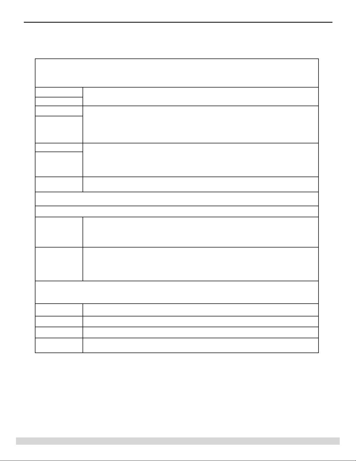
4 - ELECTRICAL SPECIFICATIONS, DIMENSIONS AND WIRING CONNECTIONS
(OHFWULFDO6SHFL¿FDWLRQV'LPHQVLRQVDQG:LULQJ&RQQHFWLRQV
(OHFWULFDO6SHFL¿FDWLRQ
TABLE 1
/LQH9ROWDJH3RZHU&RQQHFWLRQVLQ$FFRUGDQFHZLWK1(&&(&DQG/RFDO&RGHV
8VH&RSSHU&RQGXFWRUV2QO\
LINE
/1
PRIMARY PUMP
/1*
Field Power Supply, 115Vac, 50/60Hz, 1-ph, 15A Max UZ3, EZ3, EZ1, 20A Max UZ4 and UZ6
3URYLGHV3RZHUWR%RLOHU6\VWHP3ULPDU\
Pump 115Vac, 50/60Hz, 1-Ph
5DWHG)/$KS0D[LPXP$OORZDEOH3XPS
ZONE PUMPS
3URYLGHV3RZHUWR=RQH3XPSV
115Vac, 50/60Hz, 1-Ph
/1*
=5=& 9DF+]3K&RQQHFWLRQWRERLOHUOLPLWFRQWURO=5=&IRUWDQNOHVVFRLODSSOLFDWLRQV
5DWHG)/$KS0D[LPXP$OORZDEOH3XPS
Note: Total combined load of all pumps must be less than 12A for UZ3, EZ3, 7.2A for EZ1, 20A for UZ4 and UZ6
/RZ9ROWDJH&RQQHFWLRQV1(&&ODVV
+HDWLQJ&+'+:±7KHUPRVWDW&RQQHFWLRQ9DF5:&9$0D[
T
, T:&
R
'U\&RQWDFW&ORVH757:$FWLYDWLRQRI]RQHYDOYHRUSXPS
9DF%HWZHHQ75&
=RQH9DOYH&RQQHFWLRQV9DF9$0D[
1, 2, 3, 4
7HUPLQDOV±=RQH9DOYH3RZHU&RQQHFWLRQ
7HUPLQDOV=RQH9DOYH(QG6ZLWFK&RQQHFWLRQ
Note: Total combined load for all valves and thermostats must be less than 40VA for UZ3, EZ3, 24VA for EZ1,
75VA for UZ4 and UZ6
XX - 1
'U\&RQWDFW&RQQHFWWR%RLOHU77WHUPLQDOV&+5DWHG9DF$
XX - 2
XX - 3
E x p a n s i o n
Port
'U\&RQWDFW&RQQHFWWR%RLOHU77WHUPLQDOV&+5DWHG9DF$
'U\&RQWDFW&RQQHFWWR%RLOHU77WHUPLQDOV'+:5DWHG9DF$
&RQQHFWLRQIRU([SDQVLRQ0RGXOH5-
6
PN 240010923 Rev. F [07/01/2018]
Page 7
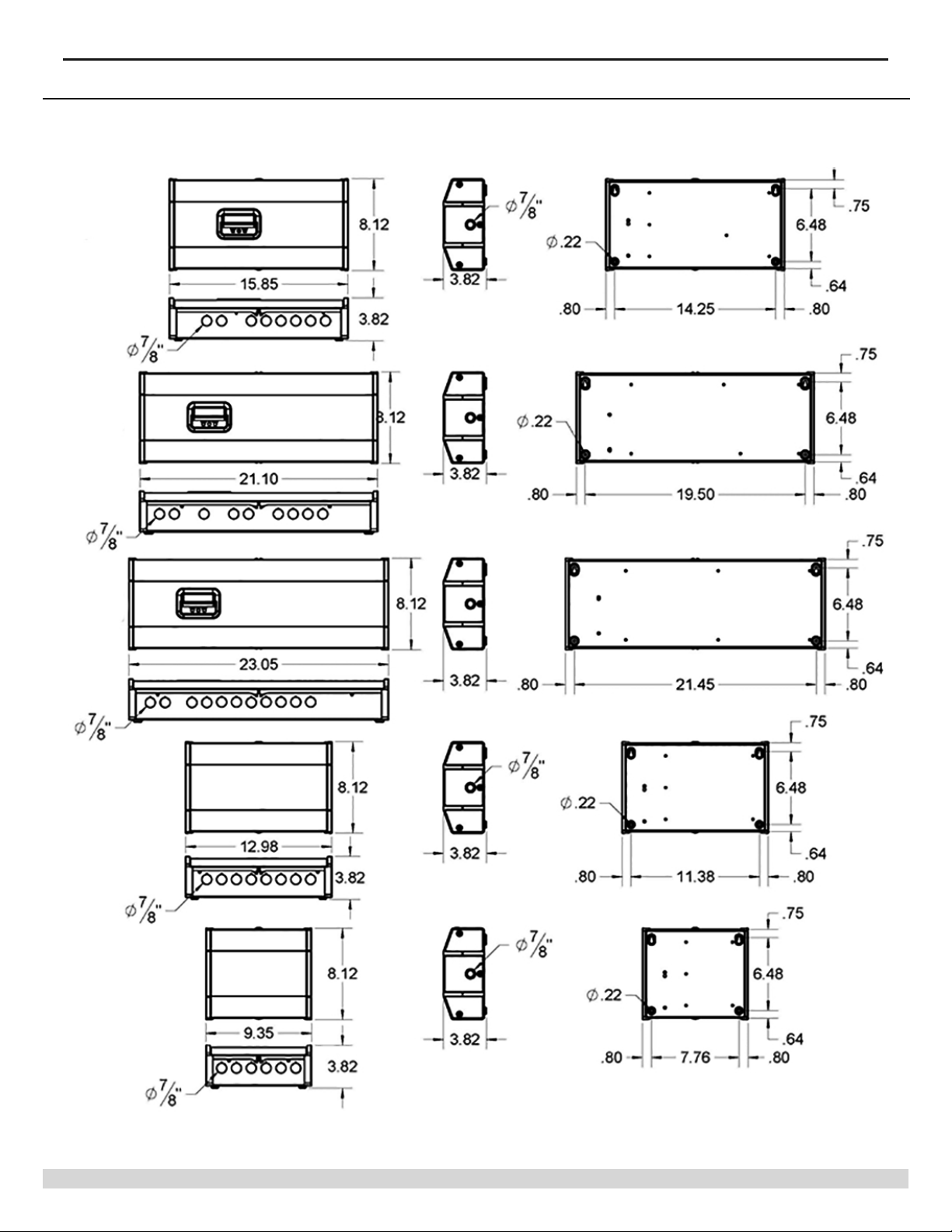
4 - ELECTRICAL SPECIFICATIONS, DIMENSIONS AND WIRING CONNECTIONS
)LJXUH'LPHQVLRQVDQG0RXQWLQJ
UZ3
UZ4
UZ6
EZ3
EZ1
7
PN 240010923 Rev. F [07/01/2018]
Page 8
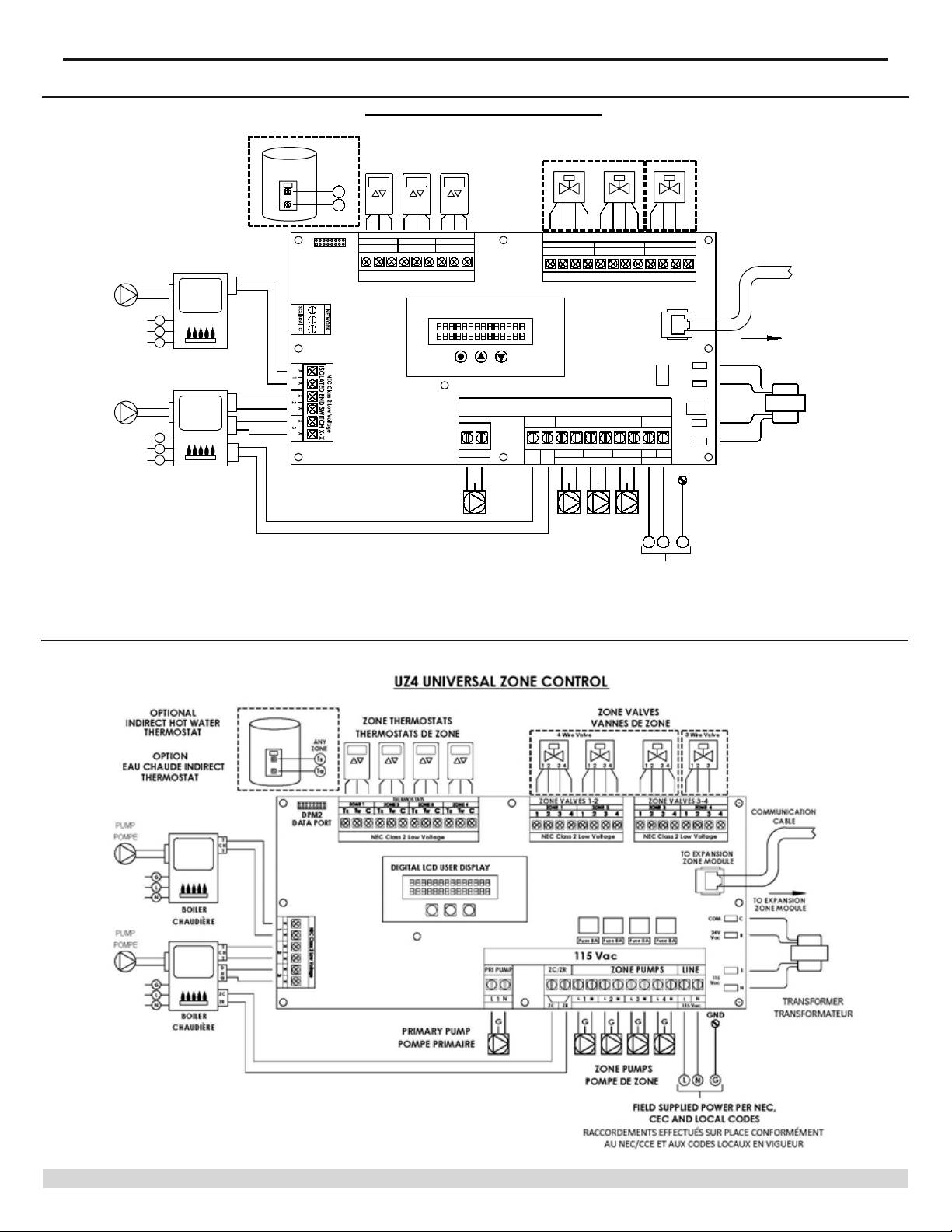
4 - ELECTRICAL SPECIFICATIONS, DIMENSIONS AND WIRING CONNECTIONS
)LJXUH&RQWURO:LULQJ8=
OPTIONAL
INDIRECT HOT WATER
THERMOSTAT
OPTION
EAU CHAUDE INDIRECT
THERMOSTAT
PUMP
POMPE
PUMP
POMPE
G
L
N
G
L
N
CHAUDIÈRE
CHAUDIÈRE
BOILER
BOILER
T
CH
T
T
CH
T
D
H
W
ZC
ZR
ANY
ZONE
T
T
DPM2
DATA PORT
UZ3 UNIVERSAL ZONE CONTROL
ZONE THERMOSTATS
THERMOSTATS DE ZONE
R
W
THERMOSTATS
ZONE 1
ZONE 2 ZONE 3
T
WTCRTWTCRTW
R
NEC Class 2 Low Voltage (24Vac)
PRIMARY PUMP
POMPE PRIMAIRE
TC
DIGITAL LCD USER DISPLAY
MODE UP DOWN
ZC/ZR
PRIMARY
1
L
N
PUMP
ZONE VALVES
VANNES DE ZONE
4 Wire Valve 3 Wire Valve
12 34 12 34 12 3
ZONE VALVES
ZONE 1
1
23412341234
NEC Class 2 Low Voltage (24Vac)
115 Vac
ZONE PUMPS
1
2
L
N
ZRZC
G
ZONE PUMPS
POMPE DE ZONE
3
L
L
N
N
GG
G
ZONE 3ZONE 2
TO EXPANSION
ZONE MODULE
COM
PTC
24V
Vac
12A 250V
LINE
115
Vac
N
L
115 Vac
GND
LNG
C
R
Fuse
L
N
COMMUNICATION
CABLE
TO EXPANSION
ZONE MODULE
TRANSFORMER
TRANSFORMATEUR
)LJXUH&RQWURO:LULQJ8=
FIELD SUPPLIED POWER PER NEC,
CEC AND LOCAL CODES
RACCORDEMENTS EFFECTUÉS SUR PLACE CONFORMÉMENT
AU NEC/CCE ET AUX CODES LOCAUX EN VIGUEUR
8
PN 240010923 Rev. F [07/01/2018]
Page 9
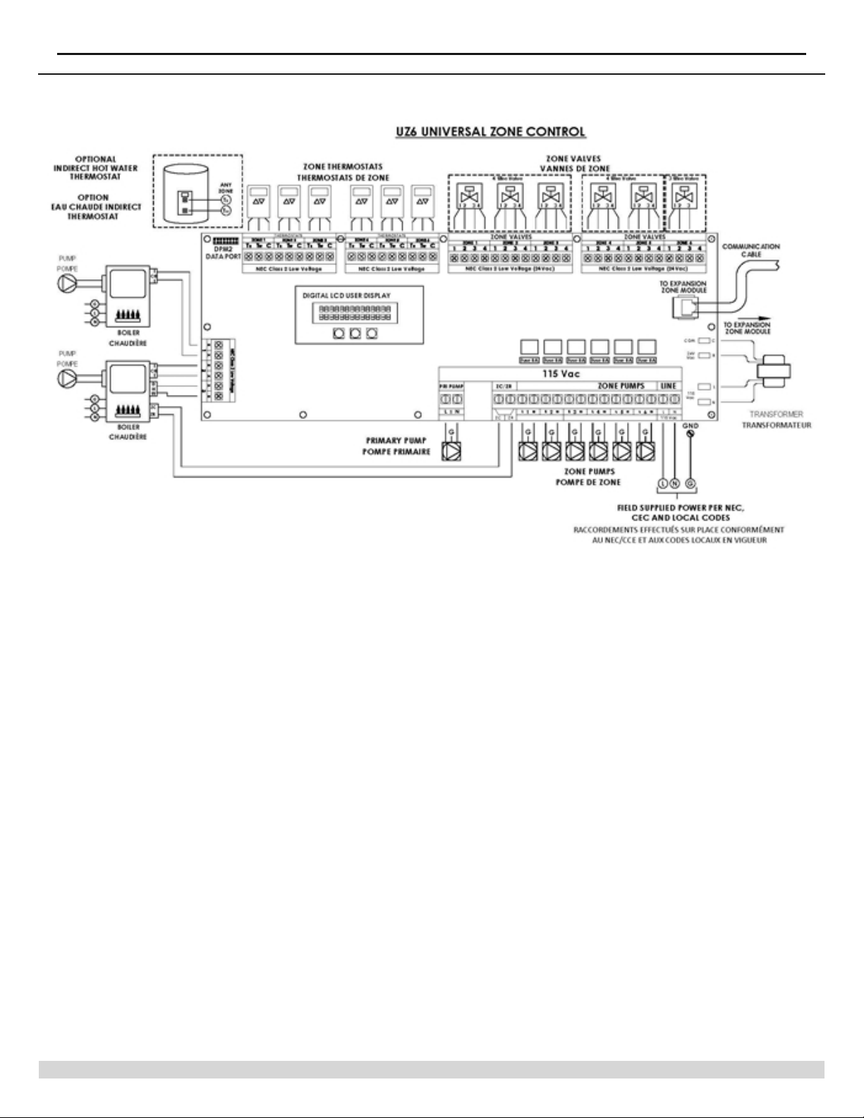
4 - ELECTRICAL SPECIFICATIONS, DIMENSIONS AND WIRING CONNECTIONS
)LJXUH&RQWURO:LULQJ8=
9
PN 240010923 Rev. F [07/01/2018]
Page 10
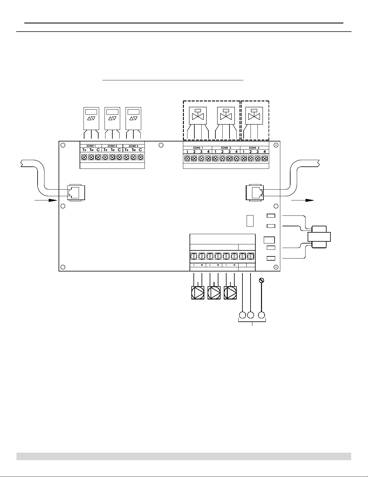
4 - ELECTRICAL SPECIFICATIONS, DIMENSIONS AND WIRING CONNECTIONS
)LJXUH&RQWURO:LULQJ(=
EZ3 EXPANSION MODULE, 3-ZONE
FROM EXPANSION
ZONE MODULE
ZONE THERMOSTATS
THERMOSTATS DE ZONE
THERMOSTATS
NEC Class 2 Low Voltage
IN OUT
ZONE VALVES
VANNES DE ZONE
4 Wire Valve 3 Wire Valve
12 34 12 34 12 3
ZONE VALVES
NEC Class 2 Low Voltage (24Vac)
EXPANSION
PORT
PTC
115 Vac
ZONE PUMPS
1
G
G
LINE
N
L
32
115 Vac
G
COM
24V
Vac
12A 250V
Fuse
115
Vac
GND
COMMUNICATION
CABLE
TO EXPANSION
ZONE MODULE
C
R
N
TRANSFORMATEUR
TRANSFORMER
ZONE PUMPS
G
N
POMPE DE ZONE
L
FIELD SUPPLIED POWER PER NEC,
CEC AND LOCAL CODES
RACCORDEMENTS EFFECTUÉS SUR PLACE CONFORMÉMENT
AU NEC/CCE ET AUX CODES LOCAUX EN VIGUEUR
10
PN 240010923 Rev. F [07/01/2018]
Page 11
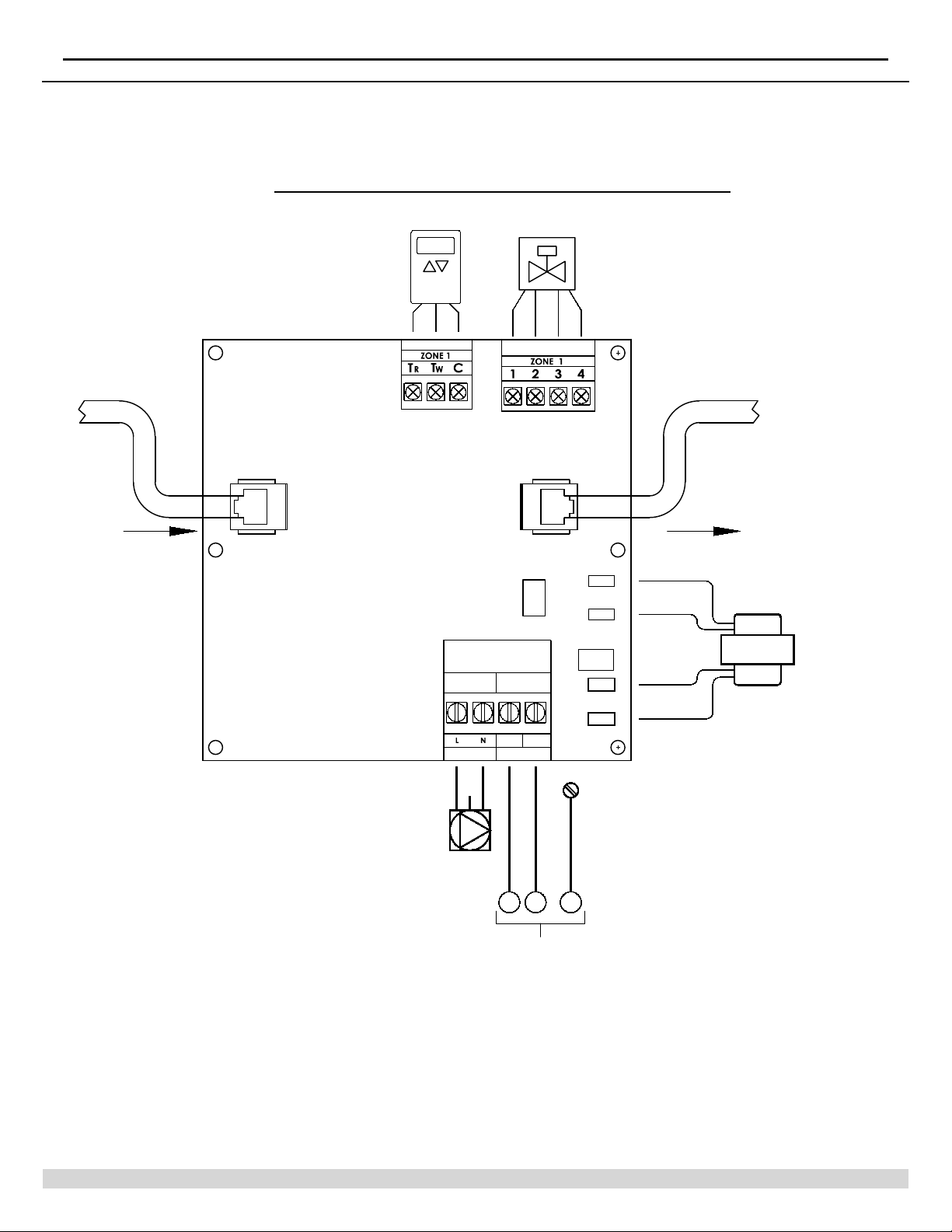
4 - ELECTRICAL SPECIFICATIONS, DIMENSIONS AND WIRING CONNECTIONS
)LJXUH&RQWURO:LULQJ(=
EZ1 EXPANSION MODULE, 1-ZONE
FROM EXPANSION
ZONE MODULE
THERMOSTAT
NEC Class 2 Low Voltage (24Vac)
IN OUT
ZONE VALVE
PTC
115 Vac
G
LINE
N
L
1
115 Vac
PUMP
COM
24V
Vac
12A 250V
Fuse
115
Vac
GND
COMMUNICATION
CABLE
TO EXPANSION
ZONE MODULE
C
R
N
TRANSFORMER
TRANSFORMATEUR
ZONE PUMP
POMPE DE ZONE
L
G
N
FIELD SUPPLIED POWER PER NEC,
CEC AND LOCAL CODES
RACCORDEMENTS EFFECTUÉS SUR PLACE CONFORMÉMENT
AU NEC/CCE ET AUX CODES LOCAUX EN VIGUEUR
11
PN 240010923 Rev. F [07/01/2018]
Page 12
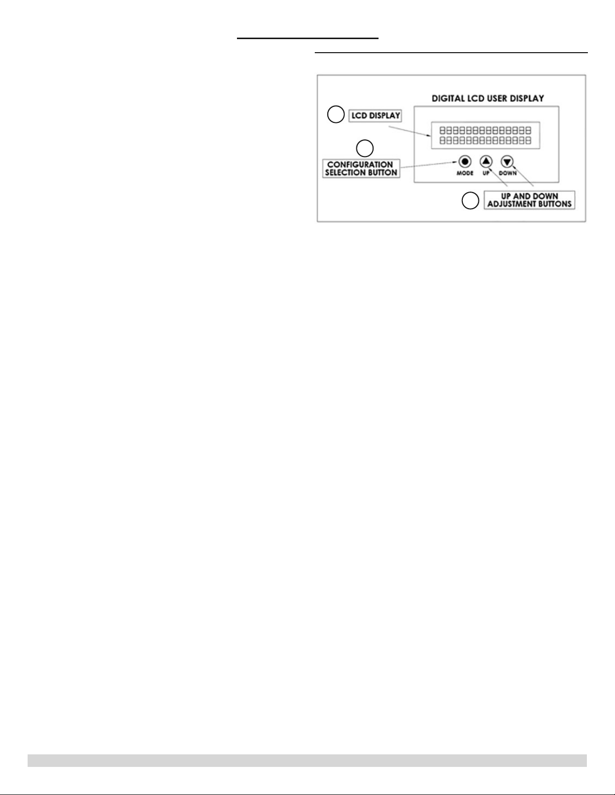
86(5,17(5)$&(
User Interface
'LJLWDOLCD8VHU'LVSOD\$QG,QWHUIDFH
A. &RQ¿JXUDWLRQ6HOHFWLRQ%XWWRQ±6HOHFWVFRQWURO
FRQ¿JXUDWLRQ3UHVVRQFHWRYLHZ]RQHVWDWXV+ROG
to enter test mode.
B. /&''LVSOD\,QGLFDWHVFRQ¿JXUDWLRQ]RQHVWDWXV
and error codes.
& 8SDQG'RZQ$GMXVWPHQW%XWWRQV±3UHVVXSDUURZ
RQFHWRYLHZFRQ¿JXUDWLRQVHWWLQJV3UHVVXSDQG
GRZQDUURZEXWWRQVWRDFFHVVFRQ¿JXUDWLRQPRGH
,QFRQ¿JXUDWLRQPRGHXVHGWRVHOHFWVHWWLQJV
)LJXUH8VHU,QWHUIDFH'LVSOD\
B
A
C
12
PN 240010923 Rev. F [07/01/2018]
Page 13

6 - CONTROL CONFIGURATION
&RQWURO&RQ¿JXUDWLRQ
=RQHFRQ¿JXUDWLRQ3XPSRU9DOYH
8VHXVHULQWHUIDFHPHQXWRFRQ¿JXUH]RQHVWDWXV
IRUSXPSRUYDOYHRSHUDWLRQ&RQ¿JXUDWLRQPHWKRG
applies to main control and all expansion modules.
3XPS'HIDXOW
• Valve
&RQ¿JXUDWLRQ0HQX
3UHVVWKHXSDUURZWRYLHZWKHFRQ¿JXUDWLRQVHWWLQJV
7RHQWHUFRQ¿JXUDWLRQPRGHSUHVVXSDQGGRZQ
arrow buttons for 5 seconds.
• Press mode button to scroll selections.
• Press up or down arrow to change settings.
• 7RH[LWFRQ¿JXUDWLRQPRGHSUHVVXSDQGGRZQ
arrow for 1 second or leave idle 2 minutes.
E. =5=&$FWLYDWLRQ±8VHGWRGHOD\DOO
pumps from operating until boiler reaches
minimum temperature.
6HOHFWLRQ±2QRU2ϑ
2Q±$OOSXPSVUHPDLQRϑXQWLO=5=&LVFORVHG
2ϑ±3XPSVDUHQRWGHSHQGHQWRQ=5=&VWDWXV
)RUYDOYHFRQ¿JXUDWLRQ]RQHWHUPLQDOV
must also be closed for primary pumps to
energize.
F. 3RVW3XUJH3XUJH7LPHU± Allows extended
zone and primary pump operation after zone call
HQGV1RWDYDLODEOHLI=5=&LVDFWLYH
6HOHFWLRQV±2ϑPPPPP
&RQWURO&RQ¿JXUDWLRQ3URJUDPPLQJ
A. Priority ±8VHGWRJLYHH[FOXVLYHRSHUDWLRQWR
VHOHFWHG]RQHV;;
2Q±:KHQSULRULW\]RQHLVHQHUJL]HG
zones will be deactivated for the
selected priority time.
2ϑ±$OO]RQHVZLOODFWLYDWHGHDFWLYDWH
equally.
end switch. Any zone assigned to XX #3
will be given priority status when priority
is on.
B. Primary pump±8VHGWRFRQWUROSULPDU\
pump in conjunction with priority zones. Not
DYDLODEOHZKHQSULRULW\LVVHWWRRϑ
,VRODWHG(QG6ZLWFK±;;LVWKHSULRULW\
Active - The primary pump will energize with a
priority call.
Inactive - The primary pump will not energize
with a priority call.
* Purge To Assignment±6HOHFWVWKHWDUJHW]RQH
for purging.
6HOHFWLRQV±$Q\]RQH«RU/DVW
&DOO
H. Pump Exercising±8VHGWRSUHYHQWSXPS
seizure due to periods of inactivity.
6HOHFWLRQV±RUGD\V
3XPS([HUFLVLQJLVQRWDYDLODEOHLI=5=&LV21
& Priority Timer±6HWVWKHPD[LPXP
SULRULW\WLPH:KHQWKHWLPHH[SLUHVSULRULW\
will be suspended for an equal time period.
6HOHFWLRQV±2ϑPPPP
90m.
D. End Switch Assignment ± $ V V L J Q V L V R O D W H G
HQGVZLWFKHV;;WR]RQHV
End switch selections are 1, 2, 3.
(QGVZLWFK;;LVWKHSULRULW\HQGVZLWFK
Any zone assigned to XX # 3 will be given
priority status. (Priority switch must be set to
RQ
13
PN 240010923 Rev. F [07/01/2018]
Page 14
6 - CONTROL CONFIGURATION
([SDQVLRQ3RUW
7KHH[SDQVLRQSRUW5-FRQQHFWLRQLVXVHGWR
connect expansion modules to the control. A low
voltage communication connect cable is provide with
the expansion module. Each expansion module is
independently powered and does not require valve or
pump power from the main controller.
Once connected the expansion module will be
recognized by the main controller. Programming of
the expansion module will occur through the main
control.
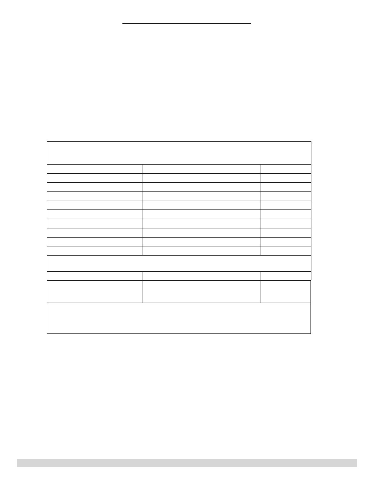
7$%/(&RQ¿JXUDWLRQ0HQX
3UHVVXSDQGGRZQDUURZEXWWRQVWRDFFHVVVHFRQGV
Then press up or down arrow button to change selection
&RQ¿JXUDWLRQ6HWWLQJ 'LVSOD\ Default
=RQH« Pump/Valve Pump
Priority 2Q2ϑ 2ϑ
3ULPDU\3XPS Active/Inactive Active
3ULRULW\7LPHU 2ϑPLQXWHV 30m
=RQH«(QG6ZLWFK 1, 2, 3 $OO
=5=& 2Q2ϑ 2ϑ
3XUJH7LPHU 2ϑVVVVV 2ϑ
3XUJH7R /DVW&DOO=RQH« /DVW&DOO
#Pump Exercising 2ϑ'D\'D\V'D\V 2ϑ
=RQH&RQ¿JXUDWLRQ
3UHVV0RGH%XWWRQWR9LHZ3XPSRU9DOYH
&RQ¿JXUDWLRQ6HWWLQJ 'LVSOD\ Default
=RQH&RQ¿JXUDWLRQ «99DOYH33XPS P-Pump
3ULPDU\SXPSDQGSULRULW\WLPHUDUHQRWDYDLODEOHLISULRULW\LV2ϑ
3XUJH7LPHULVQRWDYDLODEOHLI=5=&LV2Q
3XUJH7RLVQRWDYDLODEOHLISXUJHWLPHULV2ϑ
# 3XPS([HUFLVLQJLVQRWDYDLODEOHLI=5=&LV2Q
(jumper
LQVWDOOHG
14
PN 240010923 Rev. F [07/01/2018]
Page 15

6(48(1&(2)23(5$7,21
Sequence Of Operation
7KHUPRVWDWFDOOIRU+HDW
Field wired thermostats are connected to the
GHVLJQDWHG1(&&ODVVORZYROW]RQHWKHUPRVWDW
WHUPLQDOVGHVLJQDWHG757:&7KHFRQWUROLV
compatible with either two or three wire thermostats.
7KHKHDWLQJ]RQHWKHUPRVWDWZLOOFRQQHFW75DQG7:
energizing the corresponding zone valve, zone pump
and primary pump terminals. The designated Isolated
End Switch XX terminals will close energizing the
KHDWVRXUFHLH%RLOHURU+:YDOYH
Note: Activation of XX terminals is dependent on the programming
VHTXHQFHLQWKHFRQ¿JXUDWLRQPHQX
1RWH3ULPDU\SXPSLVDOVRGHSHQGHQWRQ=5=&FRQ¿JXUDWLRQ
Zone Pump Output
Zone pumps are wired to the designated zone pump
WHUPLQDOV:KHQWKH]RQHWKHUPRVWDWFRQQHFWV
WHUPLQDOV75DQG7:WKHFRQWUROZLOOSURYLGH9DF
DFURVVWHUPLQDOV/DQG1RIWKHFRUUHVSRQGLQJ]RQH
and the primary pump terminals of the master
control.
Note: Refer to the pump manufactures instructions
for operation and wiring.
7KHFRQ¿JXUDWLRQVHWWLQJIRU=5=&2ϑ2QDQG
3ULPDU\3XPS$FWLYH,QDFWLYHZLOODOVRDϑHFWWKH
SXPSRSHUDWLRQ5HIHUWRFRQWUROFRQ¿JXUDWLRQ
programming.
Zone Valve Output
Zone valves are wired to designated zone valve
terminals. The control is compatible with two, three
or four wire zone valves. Power to the valve is
SURYLGHGWKURXJKWHUPLQDOV7KHHQGVZLWFKLV
FRQQHFWHGWRWHUPLQDOVIRUDIRXUZLUHYDOYHRU
terminal 3 for a three-wire valve.
Note: If a 2-wire zone vale is used, then a jumper wire should be
placed across terminals 3 and 4 of the corresponding zone valve.
:KHQWKH]RQHWKHUPRVWDWFRQQHFWVWHUPLQDOV75DQG
7:WKHFRQWUROZLOOSURYLGH9DFDFURVVWHUPLQDOV
1 and 2 of the corresponding zone valve terminals.
:KHQWKH]RQHYDOYHHQGVZLWFKFORVHVSRZHUZLOO
also be supplied to the primary pump terminals of the
master control.
Note: Refer to the valve manufactures instructions for operation
and wiring.
7KHFRQ¿JXUDWLRQVHWWLQJIRU=5=&2ϑ2QDQG
3ULPDU\3XPS$FWLYH,QDFWLYHZLOODOVRDϑHFW
SXPSRSHUDWLRQ5HIHUWRFRQWUROFRQ¿JXUDWLRQ
programming.
7KHVWDWXVRI=5=&2ϑRU2QZLOODϑHFWRSHUDWLRQ
WKHSULPDU\SXPS,I³2ϑ´WKHSULPDU\SXPSLVQRW
GHSHQGHQWRQ=5=&FRQQHFWLRQ
,I³2Q´DFORVHGFRQQHFWLRQRQWHUPLQDOV=5=&
9SRZHUWR=&DOORZVWKHSULPDU\SXPSWR
HQHUJL]HDIWHU]RQHWHUPLQDOVFORVH$QRSHQ
FRQQHFWLRQ9SRZHUUHPRYHGIURP=&ZLOO
prevent the primary pump from energizing.
The operation of the primary pump for the priority
zone is also dependent on the primary pump
VHOHFWLRQPDGHLQWKHFRQ¿JXUDWLRQPHQX$FWLYHRU
,QDFWLYH,I³$FWLYH´WKHSULPDU\SXPSZLOOHQHUJL]H
ZLWKWKHSULRULW\]RQH,I³,QDFWLYH´WKHSULPDU\SXPS
will not energize with the priority zone.
7KHVWDWXVRI=5=&2ϑRU2QZLOODϑHFWRSHUDWLRQ
RIDOOSXPSRXWSXWV,I³2ϑ´SXPSRSHUDWLRQLVQRW
GHSHQGHQWRQ=5=&FRQQHFWLRQ
,I³2Q´DFORVHGFRQQHFWLRQRQWHUPLQDOV=5=&
9SRZHUWR=&DOORZVDOOSXPSVWRHQHUJL]H$Q
RSHQFRQQHFWLRQ9SRZHUUHPRYHGIURP=&ZLOO
prevent all pumps from energizing.
The operation of the primary pump for the priority
zone is also dependent on the primary pump
VHOHFWLRQPDGHLQWKHFRQ¿JXUDWLRQPHQX$FWLYHRU
,QDFWLYH,I³$FWLYH´WKHSULPDU\SXPSZLOOHQHUJL]H
ZLWKWKHSULRULW\]RQH,I³,QDFWLYH´WKHSULPDU\SXPS
will not energize with the priority zone.
3ULRULW\
3ULRULW\RSHUDWLRQDOORZVVHOHFWHG]RQHVWRKDYH
exclusive operation over other zones for a designated
time period. For priority operation, priority must be
VHWWR³2Q´LQWKHFRQ¿JXUDWLRQPHQX0XOWLSOH]RQHV
may be may be designated priority. Priority times are
VHOHFWDEOHPPPPPRU2ϑ
:KHQDSULRULW\FDOOH[LVWVIRUWKHVHOHFWHGWLPHWKH
control will then revert to non-priority operation
for an equal time period until the priority call ends.
Non-priority and priority zones will not operate
simultaneously.
)RUSULRULW\RSHUDWLRQWKHVHOHFWHG]RQHVPXVWEH
DVVLJQHGWR,VRODWHG(QG6ZLWFK;;=RQHV
assigned to Isolated End Switch #3 will be given
priority over all other zones. (Priority must be set to
RQ
15
PN 240010923 Rev. F [07/01/2018]
Page 16
6(48(1&(2)23(5$7,21
(QG6ZLWFK$VVLJQPHQW;;
The main controller is equipped with three
independent, isolated, dry contact end switches
;;;;;;IRUHQHUJL]LQJKHDWVRXUFHV
End switches can be assigned to any zone and will
close on a call for heating. End switch assignment is
VHWWKURXJKWKHFRQWUROFRQ¿JXUDWLRQSURJUDPPLQJ
menu.
:KHQSULRULW\LVVHWWRRQHQGVZLWFKHV;;DQG
XX-2 are then designated as comfort heating zones.
End switch XX-3 is then designated as the priority
]RQHHQGVZLWFK$Q\]RQHVDVVLJQHGWRHQGVZLWFK
;;ZLOOWUHDWHGDVSULRULW\]RQHV:KHQSULRULW\
]RQHVFDOOIRUKHDWDOORWKHU]RQHVZLOOQRWEH
allowed to operate until the priority time has expired
RUDOOQRQSULRULW\]RQHVDUHVDWLV¿HG
3ULPDU\3XPS
The primary pump connection is located on the
master control and is to be connected to the boiler
pump.
Note: The primary pump may be connected to the boilers
temperature control however, features such as post purge and
primary pump active/inactive cannot be utilized.
:KHQDQ\]RQHWKHUPRVWDWFRQQHFWVWHUPLQDOV75
DQG7:WKHFRQWUROZLOOSURYLGHSRZHUWRWKHSULPDU\
pump terminals
,IWKH]RQHLVFRQ¿JXUHGIRUSXPSRSHUDWLRQWKH
primary pump will energize immediately.
,IWKH]RQHLVFRQ¿JXUHGIRUYDOYHRSHUDWLRQWKHSULPDU\
pump will energize when the end switch closes contact
EHWZHHQ
1RWH5HIHUWRWKHSXPSPDQXIDFWXUHUVLQVWUXFWLRQVIRURSHUDWLRQ
and wiring.
1RWH,IDWZRZLUH]RQHYDOYHLVXVHGWKHQDMXPSHUZLUH
VKRXOGEHSODFHGDFURVVWHUPLQDOVRIWKHFRUUHVSRQGLQJ]RQH
7KHFRQ¿JXUDWLRQVHWWLQJIRU=5=&2ϑ21
DQG3ULPDU\3XPS$FWLYH,QDFWLYHZLOODOVR
DϑHFWWKHSXPSRSHUDWLRQ5HIHUWRFRQWURO
FRQ¿JXUDWLRQSURJUDPPLQJ
=5=&LQSXW
Used for tank-less coil applications to delay zone and
primary pumps from energizing.
:KHQDFWLYDWHGRSHQ=5=&FRQWDFWVZLOOGHOD\
pumps.
&ORVHG=5=&FRQWDFWVDOORZVDOOSXPSVWRHQHUJL]H
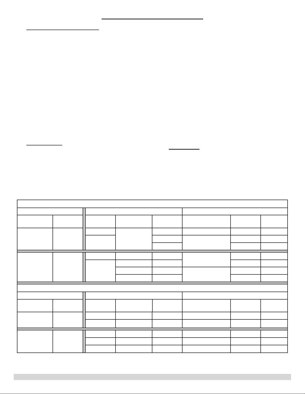
7$%/(=5=&,QSXW=RQH9DOYH2SHUDWLRQ
&RQ¿JXUDWLRQ Input Output
=RQH&RQ¿J =5=& R - W =5=& Valve 3&4 =RQH3XPS9DOYH ;;
Valve Rϑ
Valve on
open
closed
open op/cl op/cl
closed
open/closed
open op/cl open Rϑ
=&19DF open
=&19DF closed closed on
op/cl Rϑ open Rϑ
open
closed closed on
on
open Rϑ
open Rϑ
Rϑ
on
open Rϑ
7DEOH=5=&,QSXW=RQH3XPS2SHUDWLRQ
&RQ¿JXUDWLRQ Input Output
=RQH&RQ¿J =5=&
Pump Rϑ
Pump on
R - W =5=& Valve 3&4 =RQH3XPS9DOYH ;;
open op/cl n/a Rϑ open Rϑ
closed op/cl n/a on closed on
open op/cl n/a Rϑ open Rϑ
closed open n/a Rϑ open Rϑ
closed =&19DF n/a on closed on
3ULPDU\
Pump
3ULPDU\
Pump
16
PN 240010923 Rev. F [07/01/2018]
Page 17
6(48(1&(2)23(5$7,21
=5=&6XPPDU\2SHUDWLRQ
$9DOYH&RQ¿JXUDWLRQ
1. Thermostat T
%RLOHUWHPSHUDWXUHFRQWUROOHUFORVHV=5=&WXUQV
on zone valve/pump
=RQHYDOYHHQGVZLWFKFORVHVWXUQVRQ;;
and primary pump
%3XPS&RQ¿JXUDWLRQ
7KHUPRVWDW5:FORVHVFKHFNV=5=&VWDWH
%RLOHUWHPSHUDWXUHFRQWUROOHUFORVHV=5=&9
WR=&WXUQVRQ;;]RQHYDOYHSXPSDQGSULPDU\
pump.
Note:3XPS([HUFLVLQJLVQRWDYDLODEOHLI=5=&LV2Q
3RVW3XUJH3XUJH7LPHU
Post purge operation will continue to energize the
primary pump, zone pumps and zone valves at the
HQGRIDKHDWFDOOIRULPSURYHGV\VWHPHϒFLHQF\$OO
]RQHVPXVWEHVDWLV¿HGDQG=5=&PXVWEHVHWWRRϑ
for post purge to be activated.
3RVWSXUJHWLPHVDUHVHOHFWDEOHRϑGHIDXOWV
30s, 45s, 60s, 75s.
Any zone may be selected and designated as the post
purge target zone. The default target zone is the last
zone to satisfy.
3XPS([HUFLVLQJ
Pump exercising will energize zone and primary
pumps to help avoid pump seizure due to prolong
periods of inactivity. Exercising interval is based
on the amount of inactive time for each pump. The
LQWHUYDOVHOHFWLRQVDYDLODEOHDUHRϑDQGGD\V
Any pump that has not energized for the selected
time period will energize for 30s Exercising will take
place one at a time and not simultaneously. Zone
staggering delay applies to pump exercising.
3XPS([HUFLVLQJLVQRWDYDLODEOHLI=5=&LV2Q
FORVHVFKHFNV=5=&VWDWH
R-T:
([SDQVLRQ3RUW
An Expansion port is provided for controlling
additional zones. Up to 15 zones may be controlled
PD[LPXPH[SDQVLRQPRGXOHVZLWKWKHDGGLWLRQ
RIH[SDQVLRQPRGXOHV&RQWURORI;;WHUPLQDOVERLOHU
SXPSWHUPLQDOVDQG=5=&LQSXWWHUPLQDOVUHVLGHVLQ
main controller.
Each control, main controller and expansion module
is powered independently and contains individual
control transformers. Each expansion module is
independently powered and does not require valve or
pump power from the main controller.
Once connected programming selections in master
controller will be extended to the expansion module
LQFOXGLQJSULRULW\=5=&FRQWUROSXPSH[HUFLVLQJDQG
purge selections.
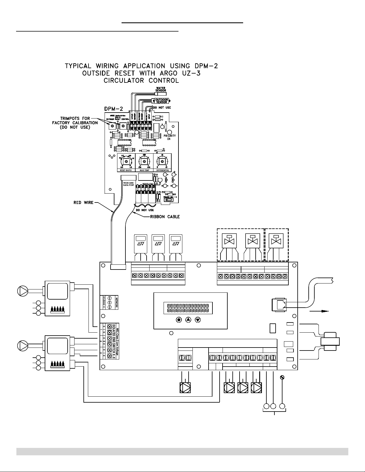
'30&RQWUROOHU3RUW
A communication port is provided through the
SLQGDWDSRUWIRUFRQQHFWLRQWR$UJRV'30
)XHO(FRQRPL]H¿JXUH7KH'30SURYLGHV
boiler set-back functionality regulating the boiler
water supply temperature according to the outdoor
ambient temperature. For more information on
'30RSHUDWLRQYLVLW$UJRVZHEVLWHDW
http://www.
argocontrols.com/
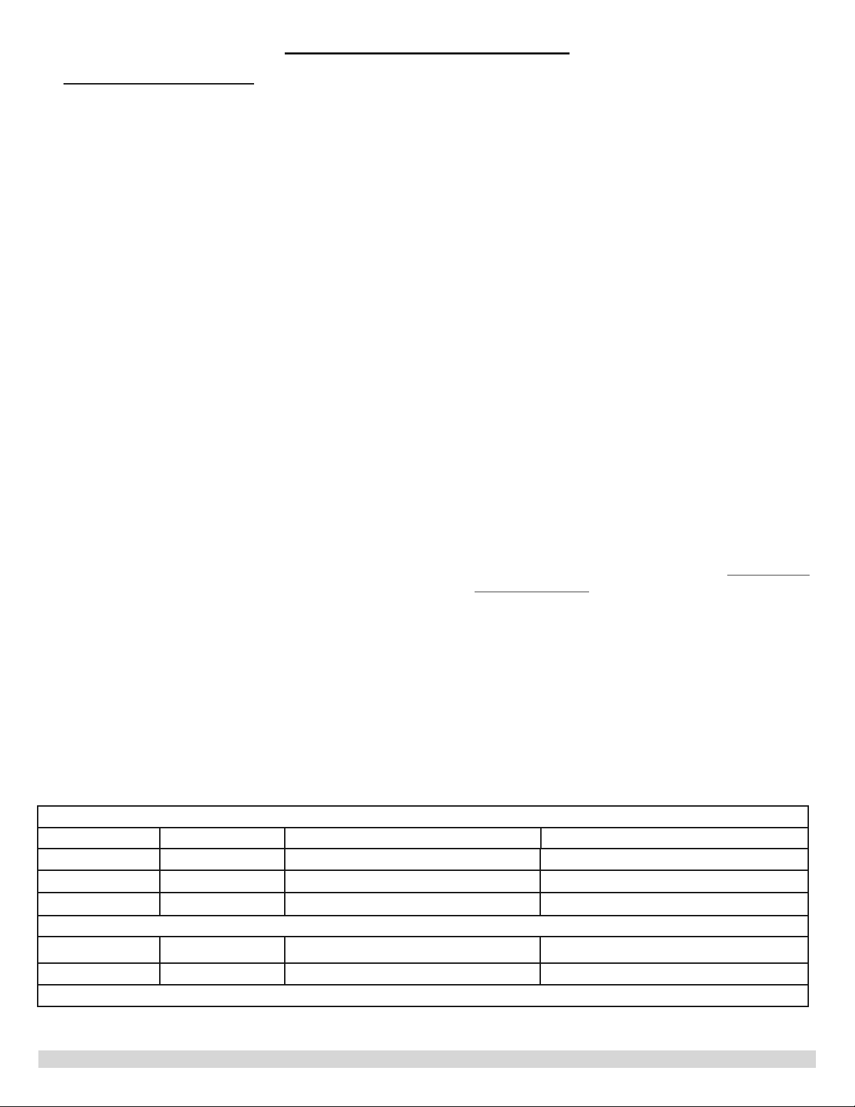
7DEOH8QLYHUVDO&RQWURODQG([SDQVLRQ0RGXOHV
Model Zones 0D[LPXP=RQHFDSDFLW\Z0DVWHU 0D[LPXPDOORZDEOHH[SDQVLRQPRGXOHV
UZ3 7KUHH 12 Zones 7KUHH
UZ4 )RXU 13 Zones 7KUHH
UZ6 6L[ 15 Zones 6L[
Expansion modules
EZ1
2QH na na
EZ3 7KUHH na na
1RWH7KHPD[LPXPQXPEHURIH[SDQVLRQPRGXOHVIRU8=LVWKUHH
17
PN 240010923 Rev. F [07/01/2018]
Page 18
)LJXUH'30:LULQJ
6(48(1&(2)23(5$7,21
PUMP
POMPE
PUMP
POMPE
G
L
N
G
L
N
BOILER
CHAUDIÈRE
BOILER
CHAUDIÈRE
T STAT
TO T-T
BOILER
24VAC
OR X-X
FROM
COMMON
ZONE VALVES
ZONE THERMOSTATS
THERMOSTATS
ZONE 1
T
DPM2
DATA PORT
T
CH
T
T
CH
T
D
H
W
ZC
ZR
R
NEC Class 2 Low Voltage (24Vac)
ZONE 2 ZONE 3
TCRTWTCRTWTC
W
DIGITAL LCD USER DISPLAY
MODE UP DOWN
PRIMARY
L
PUMP
115 Vac
ZC/ZR
1
N
VANNES DE ZONE
4 Wire Valve 3 Wire Valve
12 34 12 34 12 3
ZONE VALVES
ZONE 1
1
23412341234
NEC Class 2 Low Voltage (24Vac)
TO EXPANSION
ZONE MODULE
LINE
3
L
L
N
115 Vac
GG
ZRZC
ZONE PUMPS
1
L
L
N
G
2
N
G
ZONE 3ZONE 2
PTC
N
COM
24V
Vac
12A 250V
Fuse
115
Vac
GND
COMMUNICATION
CABLE
TO EXPANSION
ZONE MODULE
C
R
L
N
TRANSFORMER
TRANSFORMATEU
PRIMARY PUMP
POMPE PRIMAIRE
18
ZONE PUMPS
G
POMPE DE ZONE
L N
FIELD SUPPLIED POWER PER NEC,
CEC AND LOCAL CODES
RACCORDEMENTS EFFECTUÉS SUR PLACE CONFORMÉMENT
AU NEC/CCE ET AUX CODES LOCAUX EN VIGUEUR
PN 240010923 Rev. F [07/01/2018]
Page 19
7URXEOHVKRRWLQJ
7528%/(6+227,1*
!
WARNING
Electrical shock hazard. Turn OFF electrical power supply at man power switch before servicing unit. Service
VKDOOEHSHUIRUPHGE\DTXDOL¿HGVHUYLFHDJHQW)DLOXUHWRGRVRFRXOGUHVXOWLQGHDWKRUVHULRXVLQMXU\
(UURU&RGHV
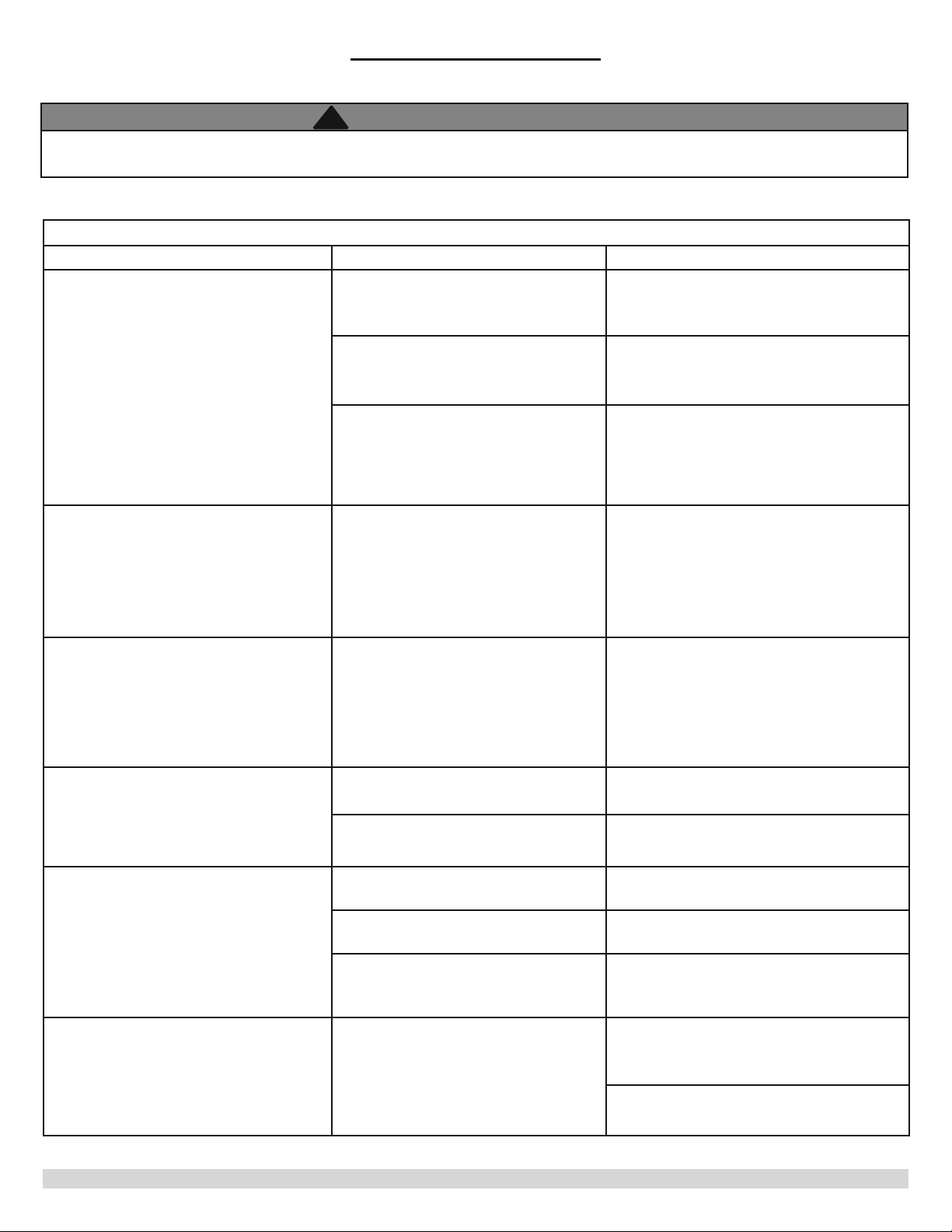
7DEOH8QLYHUVDO&RQWURO(UURU&RGHV$QG7URXEOHVKRRWLQJ
'LVSOD\RQ0DVWHU&RQWURO Possible Cause Corrective Action
/RZLQFRPLQJSRZHURQWHUPLQDOV/
DQG19DF
/RZYROWIXVH37&2SHQ
6HH&RQWURO/D\RXW
)XVH/2:9ROWDJH0000
9ROWDJHRQWHUPLQDOV5DQG&OHVVWKDQ
18 Vac.
Transformer faulty or overloaded.
Voltage High M1, M2, M3, M4 Voltage > 32 Vac
&RQWDFWHOHFWULFLDQRUORFDOSRZHUFRPSDQ\
to correct. Power should be between 104
Vac and 127 Vac.
7KHORZYROW37&IXVHLVDQDXWRUHVHW
device and is non replaceable. Should it
remain open, replace the control.
&KHFNIRUSRVVLEOHVKRUWVRUIDXOWV
LQH[WHUQDOORZYROWZLULQJ&KHFN
for excessive external loading from
thermostats or other low volt devices.
Replace, remove or correct problem.
&KHFNWKDWLQFRPLQJSRZHULVOHVVWKDQ
9DF&RQWDFWHOHFWULFLDQRUORFDOSRZHU
company to correct.
&KHFNWUDQVIRUPHU/RZ9ROW3RZHUDW
WHUPLQDOV5DQG&,IJUHDWHUWKDQ9DF
while incoming power is less than 127 Vac
then replace transformer.
9ROWDJH/RZ0000 Voltage < 18 Vac
=&+ROG±)ODVK
1RWH=&+ROGPD\GLVSOD\SHULRGLFDOO\DV
part of normal operation.
=RQH9DOYH)DLO±)ODVK
&RPP(UURU
Boiler water temperature is below
=RQH9DOYHIDLOWRFORVHWHUPLQDOV &KHFNYDOYHZLULQJ
-XPSHUPLVVLQJEHWZHHQWHUPLQDOV
&RPPXQLFDWLRQHUURUEHWZHHQPDVWHU
=5=&,QWHUUXSWLRQ
minimum
Faulty valve Replace zone valve
ZLUH]RQHYDOYHRQO\
and expansion
&KHFNWKDWLQFRPLQJSRZHULVJUHDWHUWKDQ
9DF&RQWDFWHOHFWULFLDQRUORFDOSRZHU
company to correct.
&KHFNWUDQVIRUPHU/RZ9ROW3RZHUDW
WHUPLQDOV5DQG&,IOHVVWKDQ9DF
while incoming power is greater than 104
Vac then replace transformer.
&KHFNZLULQJEHWZHHQ8QLYHUVDOFRQWURO
and boiler controller
&KHFNIRUFRUUHFWERLOHURSHUDWLRQ
&RUUHFWDVQHHGHG
Add jumper wire on zone valve terminals
&KHFNFRPPXQLFDWLRQZLUHEHWZHHQ
master control and expansions modules.
Replace if faulty.
&KHFNWUDQVIRUPHUSRZHUDWWHUPLQDOV5
DQG&LV9DF
19
PN 240010923 Rev. F [07/01/2018]
Page 20
7528%/(6+227,1*
7DEOH8QLYHUVDO&RQWURO(UURU&RGHV$QG7URXEOHVKRRWLQJ
'LVSOD\RQ0DVWHU&RQWURO Possible Cause Corrective Action
Reduce number of expansion
Too Many Exp Modules
Display is blank
Exceeded maximum allowable
expansion modules
No incoming power &KHFN¿HOGFLUFXLWEUHDNHU
On board fuse is open
m o d u l e s t o a l l o w a b l e n u m b e r.
6HH6HTXHQFHRI2SHUDWLRQ±([SDQVLRQ
Port.
&KHFNIRUSRVVLEOHVKRUWFLUFXLWVLQSXPS
connections.
&KHFNIRUIDXOW\SXPSV
&KHFNIRUH[FHVVLYHSXPSORDGV7KHWRWDO
pump load for each control should NOT
H[FHHGPD[LPXPVSHFL¿FDWLRQV
9- REPLACEMENT PARTS
Part Description
Part
Number
´7HOHSKRQHFDEOHFRQQHFWRU 5-
)LHOGPRXQWHG9$WUDQVIRUPHU8= 119000002
Field-mounted 40 VA transformer (EZ1 240010835
7(&+1,&$/6833257
&RQWDFW(&5,QWHUQDWLRQDO7HFKQLFDO6HUYLFHIRUWHFKQLFDOVXSSRUWIRU$UJRSURGXFWV
Have model number available when calling.
Information NHHGHG:KHQCDOOLQJ
Model Number
Installation Date
Installer
2201 Dwyer Avenue, Utica, NY 13501
Tel. 800 253 7900
www.ecrinternational.com
BDR THERMEA GROUP
''.+ $ޔ/$*)..0% //*#)" 2$/#*0/)*/$ ѵ
©2018 ECR International, Inc.
 Loading...