

Page 1
EG
I
F
D
E
Power Supply:
230V / 1 / 50Hz *400 V / 3N / 50 Hz
1.Standard screwdriver
2.Phillips head screwdriver
3.Knife or wire stripper
4.Tape measure
5.Level
6.Sabre saw or key hole saw
7.Hacksaw
8. Core bits ø 5
19.Hammer
10.Drill
11.Tube cutter
12.Tube flaring tool
13.Torque wrench
14.Adjustable wrench
15.Reamer (for reburring)
16.Hex. key
Tools required for installation (not supplied)
Model Combinations
Combine indoor and outdoor units only as listed below.
Indoor Units Outdoor Units
AW726CL AE726SCL
AW726CLF
AW735CL AE735SCL
AW735CLF
FC735CL AE735SCL
AW752CL AE752SCL
AE752SCL3 *
FC752CL AE752SCL
AE752SCL3 *
AW764CL AE764SCL3 *
FC764CL AE764SCL3 *
Indoor Units
Outdoor Units
AW720HL AE720SH
AW726HL AE726SH
AW726HLF
AW735HL AE735SH
AW735HLF
AW752HL AE752SH
AW764HL AE764SH
AE764SH3 *
37.4255.043.01 11/2014
INSTALLATION INSTRUCTIONS
- Split system air conditioner -
P
GR
OPERATING LIMITS
L
Maximum conditions
Outdoor temperature : 43°C D.B.
Room temperature : 32°C D.B. / 23°C W.B.
L
Minimum conditions
Outdoor temperature : –15°C D.B.
Room temperature : 19°C D.B. / 14°C W.B.
OPERATING LIMITS
L
Cooling Maximum conditions
Outdoor temperature : 43°C D.B.
Room temperature : 32°C D.B. / 23°C W.B.
L
Cooling Minimum conditions
Outdoor temperature : 19°C D.B.
Room temperature : 19°C D.B. / 14°C W.B.
L
Heating Maximum conditions
Outdoor temperature : 24°C D.B. / 18°C W.B.
Room temperature : 27°C D.B.
L
Heating Minimum conditions
Outdoor temperature : –8°C D.B. / –9°C W.B.
COOLING Models
HEAT PUMP Models
COOLING Models
HEAT PUMP Models
REGULATION (EU) No. 517/2014 - F-GAS
The unit contains R410A, a fluorinated greenhouse gas with
a global warming potential (GWP) of 2087.50. Do not
release R410A into the atmosphere.
DECLARATION OF CONFORMITY
This product is marked as it satisfies Directives:
–Low voltage no. 2006/95/EC.
(Standard: EN60335-2-40:2003 (incl. Corr.:2006) + A11:2004 + A12:2005 + A13:2012
+ A1:2006 + A2:2009 con EN 60335-1:2002 + A1 1:2004 + A1:2004 + A12:2006 + A2:2006 + A13:2008 + A14:2010 +
A15:2011).
–Electromagnetic compatibility no. 2004/108/EC, 92/31 EEC and 93/68 EEC.
(Standard: EN55014-1 (2006) + A1(2009)
+ A2(2011), EN 55014-2 (1997) + A1(2001) + A2 (2008), EN 61000-3-2 (2006) + A1(2009) + A2(2009),
EN 61000-3-3 (2008)
–RoHS2 no.2011/65/EU.
–Regulation (EU) no. 206/2012, of 6 march 2012, concerning the specifications for ecodesign requirements of air
conditioners and fans.
–Regulation (EU) no. 626/2011, of 4 may 2011, concerning the labeling indicating the energy consumption of air
conditioners.
This declaration will become void in case of misuse and/or non observance though partial of manufacturer's installation
and/or operating instructions.
Page 2
2
IMPORTANT!
Please read before installation
This air conditioning system meets strict safety and operating
standards.
For the installer or service person, it is important to install
or service the system so that it operates safely and efficiently .
For safe installation and trouble-free operation,
you must:
• Carefully read this instruction booklet before beginning.
• Follow each installation or repair step exactly as shown.
• Observe all local, state and national electrical codes.
• Pay close attention to all warning and caution notices
given in this manual.
•The unit must be supplied with a dedicated electrical line.
This symbol refers to a hazard or unsafe practice which
can result in severe personal injury or death.
This symbol refers to a hazard or unsafe practice which
can result in personal injury or product or property damage.
If necessary, get help
These instructions are all you need for most installation
sites and maintenance conditions.
If you require help for a special problem, contact our
sale/service outlet or your certified dealer for additional
instructions.
In case of improper installation
The manufacturer shall in no way be responsible for improper
installation or maintenance service, including failure to follow
the instructions in this document.
SPECIAL PRECAUTIONS
• During installation, connect before the refrigerant system
and then the wiring one; proceed in the reverse orden
when removing the units.
When wiring
ELECTRICAL SHOCK CAN CAUSE SEVERE
PERSONAL INJURY OR DEATH. ONLY A
QUALIFIED, EXPERIENCED ELECTRICIANS
SHOULD ATTEMPT TO WIRE THIS SYSTEM.
• Do not supply power to the unit until all wiring and tubing
are completed or reconnected and checked, to ensure
the grounding.
• Highly dangerous electrical voltages are used in this
system. Carefully refer to the wiring diagram and these
instructions when wiring.
Improper connections and inadequate grounding can
cause accidental injury and death.
• Ground the unit following local electrical codes.
• The Y ellow/Green wire cannot be used for any connection
different from the ground connection.
• Connect all wiring tightly. Loose wiring may cause
overheating at connection points and a possible fire
hazard.
• Do not allow wiring to touch the refrigerant tubing,
compressor, or any moving parts of the fan.
• Do not use multi-core cable when wiring the power supply
and control lines. Use separate cables for each type of line.
When transporting
Be careful when picking up and moving the indoor and
outdoor units. Get a partner to help, and bend your knees
when lifting to reduce strain on your back. Sharp edges or
thin aluminium fins on the air conditioner can cut your fingers.
When installing...
... In a ceiling or wall
Make sure the ceiling/wall is strong enough to hold the unitweight. It may be necessary to build a strong wooden or
metal frame to provide added support.
... In a room
Properly insulate any tubing run inside a room to prevent
"sweating", which can cause dripping and water damage to
walls and floors.
... In moist or uneven locations
Use a raised concrete base to provide a solid level
foundation for the outdoor unit.
This prevents damage and abnormal vibrations.
... In area with strong winds
Securely anchor the outdoor unit down with bolts and a
metal frame. Provide a suitable air baffle.
... In a snowy area (for heat pump-type systems)
Install the outdoor unit on a raised platform that is higher than
drifting snow. Provide snow vents.
When connecting refrigerant tubing
• Keep all tubing runs as short as possible.
• Use the flare method for connecting tubing.
• Apply refrigerant lubricant to the matching surfaces of
the flare and union tubes before connecting them; screw
by hand and then tighten the nut with a torque wrench
for a leak-free connection.
• Check carefully for leaks before starting the test run.
NOTE:
Depending on the system type, liquid and gas lines may
be either narrow or wide. Therefore, to avoid confusion, the
refrigerant tubing for your particular model is specified as
narrow tube for liquid, wide tube for gas.
When servicing
• Turn the power OFF at the main power board before
opening the unit to check or repair electrical parts and
wiring.
• Keep your fingers and clothing away from any moving
parts.
• Clean up the site after the work, remembering to check
that no metal scraps or bits of wiring have been left inside
the unit being serviced.
• Ventilate the room during the installation or testing the
refrigeration system; make sure that, after the installation,
no gas leaks are present, because this could produce
toxic gas and dangerous if in contact with flames or heatsources.
WARNING
CAUTION
WARNING
EG
Page 3
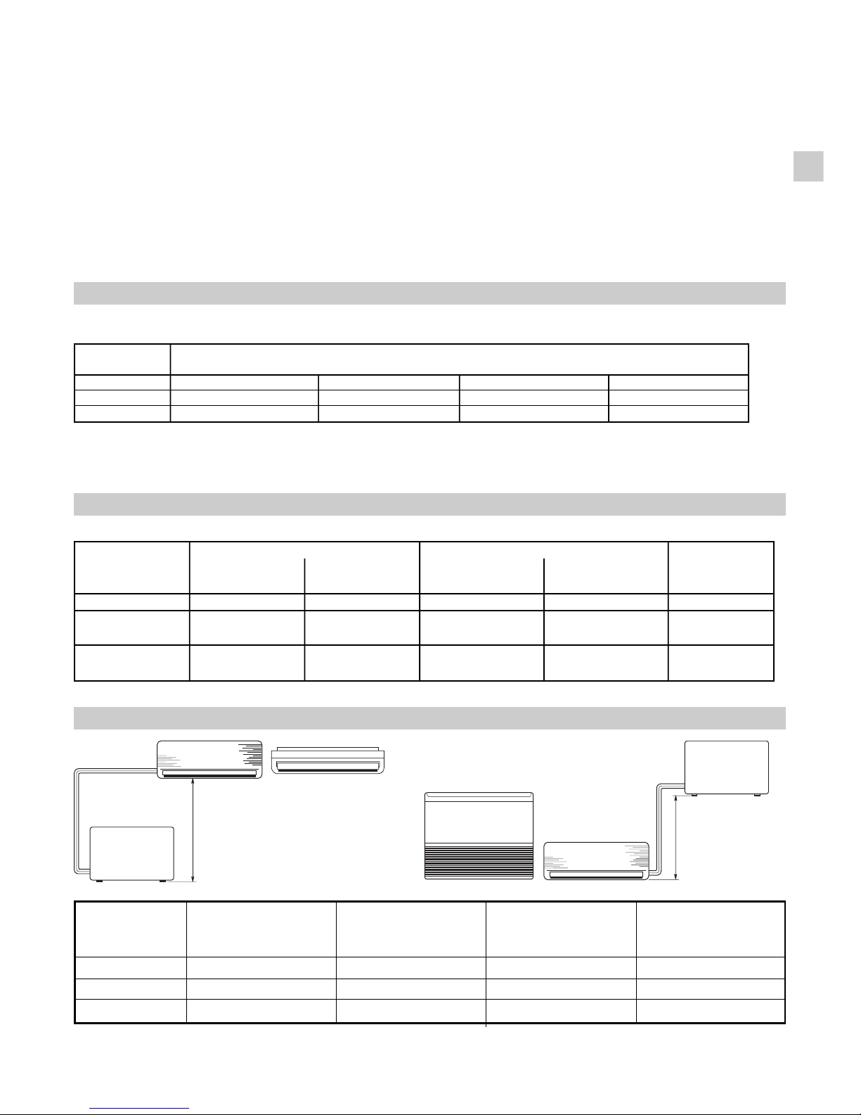
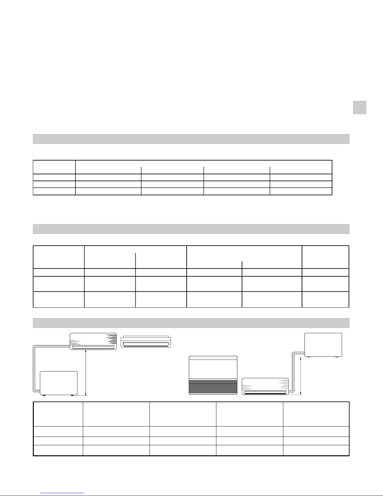
AW-FCX20-26-35 7,5 15 7 20
AW-FCX52 10 20 15 20
AW-FCX64 12,5 30 15 25
MODEL
MAX. ALLOWABLE LIMIT OF TUBING LIMIT OF ELEV A TION REQUIRED AMOUNTOF
TUBING LENGTH AT LENGTH DIFFERENCE ADDITIOONAL
SHIPMENT H REFRIGERANT
(m) (m) (m) (g / m)*
3
Installation site selection - Indoor unit
AVOID
• Direct sunlight.
• Nearby heat sources that may affect unit performance.
• Areas where leakage of flammable gas may be expected.
• Locations where large amounts of oil mist may occur
(such as in kitchen or near factory equipment) because
oil contamination can cause operation problems and may
deform plastic surfaces and parts of the unit.
• Unsteady locations that will cause noise or possible water
leakage.
• Locations where the remote control unit will be splashed
with water or affected by dampness or humidity.
• T o make holes in areas where electrical wiring or conduits
are located.
DO
• Select an appropriate position from which every corner of
the room can be uniformily cooled.
• Select a sufficiently strong location to support the weight
of the unit.
• Select a location where tubing and drain hose have the
shortest run to the outside.
• Allow access for operation and maintenance as well as
unrestricted air flow around the unit.
Installation site selection - Outdoor unit
AVOID
• Heat sources, exhaust fans.
• Direct sunlight.
• Damp, humid or uneven locations.
• T o make holes in areas where electrical wiring or conduits
are located.
DO
• Choose places as cool as possible and well ventilated.
• use lug bolts or equal to bolt down the unit, reducing
vibration and noise.
ADDITIONAL MATERIAL REQUIRED FOR INSTALLATION (NOT SUPPLIED)
l Deoxidized annealed copper tube for refrigerant tubing connecting the units of the system; it has to be insulated with
foamed polyethylene (min. thickness 8mm).
l PVC pipe for condensate drain pipe (ø int.18mm) in lenght suitable to let the condensate flow into the outside drainage.
l Anti-freeze oil for flare connections (about 30g).
l Electric wire: use insulated copper wires of size and length as shown in the table “ELECTRICAL DAT A” and at paragraph
“SYSTEM WIRING DIAGRAMS”.
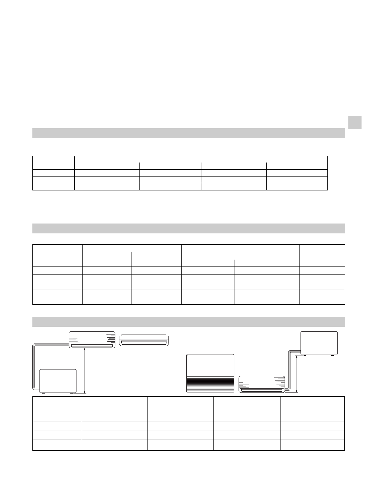
ELECTRICAL DATA
LENGTH, SIZE WIRES AND DELAYED FUSE
TUBING LENGTH AND ELEVATION DIFFERENCE LIMITS
H
H
(go on page 4)
EG
* For every meter of tube more than standard lenght at shipment, add refrigerant as shown in the table. No additional charge
of compressor oil is necessary.
Delayed fuse
MODEL Cross section Cross section
(A) m
area (mm2) (B) m area (mm2)
AEX20-26-35 15 1,5 15 1,5 10 A
AEX52 15 2,5 25 1,5 16 A
85 *
AEX64 15 2,5 20 1,5 16 A
65 *
Power supply wiring length
Power line/Control line length
*
3-phase version
MODEL
OUTER DIAMETER MIN. THICKNESS OUTER DIAMETER MIN. THICKNESS
AWX20-26
6,35 mm 0,8 mm 9,52 mm 0,8 mm
AW-FCX35-52
6,35 mm 0,8 mm 12,7 mm 0,8 mm
AW-FCX64
6,35 mm 0,8 mm 15,88 mm 1 mm
NARROW TUBE
LARGE TUBE
Page 4

Page 5
Alimentazione elettrica:
230V / 1 / 50Hz *400 V / 3N / 50 Hz
1.Cacciavite a lama
2.Cacciavite medio a
stella
3.Forbici spelafili
4.Metro
5.Livella
6.Punta fresa a tazza
7.Seghetto
8.Punta da trapano ø 5
19.Martello
10.Trapano
11.Tagliatubi a coltello rotante
12.Flangiatubi a giogo per
attacco a cartella
13.Chiave dinamometrica
14.Chiavi fisse o a rullino
15.Sbavatore
16.Chiave esagonale
Attrezzi necessari per l’installazione (non forniti)
I
37.4255.043.01 11/2014
ISTRUZIONI DI INSTALLAZIONE
- Condizionatore d’aria Split System -
LIMITI DI FUNZIONAMENTO
L
Condizioni Massime
Temperatura esterna : 43°C B.S.
Temperature interne : 32°C B.S. / 23°C B.U.
L
Condizioni Minime
Temperatura esterna : –15°C B.S
Temperature interne : 19°C B.S. / 14°C B.U.
LIMITI DI FUNZIONAMENTO
L
Condizioni Massime in Raffreddamento
Temperatura esterna : 43°C B.S.
Temperature interne : 32°C B.S. / 23°C B.U.
L
Condizioni Minime in Raffreddamento
Temperatura esterna : 19°C B.S.
Temperature interne : 19°C B.S. / 14°C B.U.
L
Condizioni Massime in Riscaldamento
Temperature esterne : 24°C B.S. / 18°C B.U.
Temperature interne : 27°C B.S.
L
Condizioni Minime in Riscaldamento
Temperature esterne : –8°C B.S. / –9°C B.U.
Combinazione Modelli
Combinare Unità Interna ed Esterna solo come elencato
qui sotto.
Unità interne
Unità esterne
AW726CL AE726SCL
AW726CLF
AW735CL AE735SCL
AW735CLF
FC735CL AE735SCL
AW752CL AE752SCL
AE752SCL3 *
FC752CL AE752SCL
AE752SCL3 *
AW764CL AE764SCL3 *
FC764CL AE764SCL3 *
Unità interne
Unità esterne
AW720HL AE720SH
AW726HL AE726SH
AW726HLF
AW735HL AE735SH
AW735HLF
AW752HL AE752SH
AW764HL AE764SH
AE764SH3 *
COOLING Models
HEAT PUMP Models
COOLING Models
HEAT PUMP Models
REGOLAMENTO (UE) N. 517/2014 - F-GAS
L’unità contiene R410A, un gas fluorurato a ef fetto serra,
con potenziale di riscaldamento globale (GWP) = 2087,50.
Non disperdere R410A nell’ambiente.
DICHIARAZIONE DI CONFORMITÀ
Questo prodotto è marcato in quanto conforme alle Direttive:
–Bassa Tensione n. 2006/95/CE (Standard: EN60335-2-40:2003 (incl. Corr .:2006) + A11:2004 + A12:2005 + A13:2012
+ A1:2006 + A2:2009 with EN 60335-1:2002 + A11:2004 + A1:2004 + A12:2006 + A2:2006 + A13:2008 + A14:2010 +
A15:2011).
–Compatibilità Elettromagnetica n. 2004/108/CE, 92/31 CEE e 93/68 CEE. (Standard: EN55014-1 (2006) + A1(2009)
+ A2(2011), EN 55014-2 (1997) + A1(2001) + A2 (2008), EN 61000-3-2 (2006) + A1(2009) + A2(2009),
EN 61000-3-3 (2008)
–RoHS2 n.2011/65/UE.
–Regolamento (UE) n. 206/2012, del 6 marzo 2012, relativo alle specifiche per la progettazione ecocompatibile dei
condizionatori d’aria e dei ventilatori.
– Regolamento (UE) n. 626/2011, del 4 maggio 2011, relativo all’etichettatura indicante il consumo d’energia dei
condizionatori d’aria.
Questa dichiarazione sarà nulla nel caso di impiego diverso da quello dichiarato dal Fabbricante e/o di mancata
osservanza, anche solo parziale, delle istruzioni d'installazione e/o d'uso.
Page 6
2
IMPORTANTE!
Leggere prima di iniziare l’installazione
Questo sistema di condizionamento deve seguire rigidi
standard di sicurezza e di funzionamento.
Per l’installatore o il personale di assistenza è molto
importante installare o riparare il sistema di modo che
quest’ultimo operi con sicurezza ed efficienza.
Per un’installazione sicura e un buon
funzionamento è necessario:
• Leggere attentamente questo manuale di istruzioni prima
di iniziare.
• Seguire tutte le istruzioni di installazione o riparazione
esattamente come mostrato.
• Osservare tutte le norme elettriche locali, statali e nazionali.
• Fare molta attenzione a tutte le note di avvertimento e di
precauzione indicate in questo manuale.
• Per l’alimentazione dell’unità utilizzare una linea elettrica
dedicata.
Questo simbolo si riferisce a pericolo o utilizzo improprio che
possono provocare lesioni o morte.
Questo simbolo si riferisce a pericolo o utilizzo improprio che
possono provocare lesioni, danni all’apparecchio o
all’abitazione.
Se necessario, chiedi aiuto
Queste istruzioni sono tutto quello che necessita per la
maggior parte delle tipologie di installazione e manutenzione.
Nel caso in cui servisse aiuto per un particolare problema,
contattare i nostri punti di vendita/assistenza o il vostro
negoziante per ulteriori informazioni.
In caso di installazione errata
La ditta non è responsabile di un’errata installazione o
manutenzione qualora non vengano rispettate le istruzioni
di questo manuale.
PARTICOLARI PRECAUZIONI
• Durante l’installazione eseguire prima il collegamento del
circuito frigorifero e poi quello elettrico, procedere in
modo inverso nel caso di rimozione delle unità.
Quando è elettrico
LA SCARICA ELETTRICA PUÒ CAUSARE
LESIONI MOLTO GRAVI O LA MORTE. SOLO
ELETTRICISTI QUALIFICATI ED ESPERTI
POSSONO MANIPOLARE IL SISTEMA
ELETTRICO.
• Non alimentare l’unità finché tutti i cavi e i tubi non siano
completati o ricollegati e controllati, per assicurare le
messa a terra.
• In questo circuito elettrico vengono utilizzati voltaggi
elettrici altamente pericolosi. Fare riferimento allo schema
elettrico e a queste istruzioni durante il collegamento.
Collegamenti impropri e inadeguata messa a terra
possono causare lesioni accidentali o la morte.
• Eseguire la messa a terra dell’unità secondo le norme
elettriche locali.
• Il conduttore giallo/verde non può essere utilizzato per
collegamenti diversi dalla messa a terra.
• Fissare bene i cavi. Collegamenti inadeguati possono
causare surriscaldamento e un possibile incendio.
• I cavi elettrici non devono venire a contatto con i tubi
refrigeranti, il compressore o le parti mobili del ventilatore.
• Nel collegare l’alimentazione e le linee di controllo, non
usare cavi a più conduttori. Usare cavi separati per ciascun
tipo di linea.
Durante il trasporto
Fare attenzione nel sollevare e nello spostare le unità interna
ed esterna. È consigliabile farsi aiutare da qualcuno e
piegare le ginocchia quando si solleva per evitare strappi
alla schiena. Bordi affilati o sottili fogli di alluminio del
condizionatore potrebbero procurarvi dei tagli alle dita.
Durante l’installazione...
... A soffitto, a muro o a pavimento
Assicurarsi che siano abbastanza resistenti da reggere il
peso dell’unità. Potrebbe essere necessario costruire un
telaio in legno o metallo per provvedere a un supporto
maggiore.
... In un locale
Isolare accuratamente ogni tubazione nel locale per
prevenire formazione di condensa che potrebbe causare
gocciolamento e, di conseguenza, arrecare danni a muri e
pavimenti.
... In luoghi umidi o irregolari
Usare una base solida e rialzata dal terreno per predisporre
l’Unità Esterna.
Questo eviterà danni e vibrazioni anormali.
... In luoghi altamente ventilati
Ancorare saldamente l’unità esterna con bulloni e un telaio
in metallo. Provvedere a un adatto deflettore per l’aria.
... In luoghi soggetti a nevicate (per i condizionatori
pompa calore)
Installare l’Unità Esterna su una piattaforma più alta del
livello di accumulo della neve. Provvedere a un’apertura di
sfogo per la neve.
Collegando il circuito frigorifero
• Tenere le tubazioni più corte possibili.
• Usare il metodo di cartellatura per collegare i tubi.
• Oliare con olio anticongelante le superfici di contatto della
cartellatura e avvitare con le mani, quindi stringere le
connessioni utilizzando una chiave dinamometrica in
modo da ottenere un collegamento a buona tenuta.
• Verificare attentamente l’esistenza di eventuali perdite
prima della prova di funzionamento (test run).
NOTA:
Asecondo del tipo di sistema, le tubazioni per liquidi o gas
possono essere sia piccole che grandi. Per evitare
confusione, parlando di tubazione refrigerante, sarà
specificato: tubo piccolo per liquido, grande per gas.
Durante le riparazioni
• Togliere tensione (dall’interruttore generale) prima di aprire
l’unità per controllare o riparare parti elettriche.
• Tenere lontano mani e vestiti da ogni parte mobile.
• Pulire dopo aver terminato il lavoro, controllando di non
aver lasciato scarti metallici o pezzi di cavo all’interno
dell’unità.
• Areare il locale durante l’installazione e la prova del circuito
refrigerante; assicurarsi inoltre che, una volta completata
l’installazione, non si verifichino perdite di gas refrigerante
poiché il contatto con fiamme o fonti di calore può essere
tossico e molto pericoloso.
AVVERTIMENTO
PRECAUZIONE
AVVERTIMENTO
GIG
Page 7

MASSIMA LUNGHEZZA MASSIMA LUNGHEZZA MASSIMO DISLIVELLO QUANTITÁ DI
TUBAZIONI CON CARICA TUBAZIONI AMMISSIBILE AMMISSIBILE REFRIGERANTE
REFRIGERANTE STANDARD
H AGGIUNTIVA
(m) (m) (m) (g / m)*
3
Scelta del luogo di installazione unità interna
EVITARE
• L’esposizione diretta al sole.
• La vicinanza a fonti di calore che possono danneggiare
la struttura dell’unità.
• La presenza di perdite di gas.
• La presenza di vapori d’olio (come in una cucina o vicino
a macchinari industriali) perché la contaminazione d’olio
può provocare malfunzionamento e può deformare
superfici e particolari in plastica dell’unità.
• Locali con piani di appoggio malfermi che possono causare
vibrazione, rumore o possibili perdite d’acqua.
• Luoghi dove il telecomando possa essere soggetto a
spruzzi d’acqua o umidità eccessiva.
• Di eseguire fori nelle zone dove si trovano parti elettriche
o impianti.
È PREFERIBILE
• Scegliere la posizione appropriata dalla quale ogni angolo
del locale possa essere uniformemente climatizzato.
• Verificare che il piano di appoggio sia sufficientemente
resistente da sostenere il peso dell’unità.
• Scegliere una posizione in modo che la distanza tra le
due unità sia la minore possibile.
• Scegliere la posizione più appropriata per assicurare una
buona ventilazione e spazi minimi di manutenzione intorno
all’unità.
Scelta del luogo di installazione unità esterna
EVITARE
• La vicinanza a fonti di calore o ad aree interessate da
espulsioni di aria calda.
• L’esposizione diretta al sole.
• Zone umide o soggette ad allagamenti e piano di appoggio
non livellato.
• Di eseguire fori nelle zone dove si trovano parti elettriche
o impianti.
È PREFERIBILE
• Scegliere aree possibilmente in ombra e leggermente
ventilate.
• Fissare l’unità alla base di appoggio per evitare vibrazioni.
MATERIALE ADDIZIONALE PER L'INSTALLAZIONE (NON FORNITO)
l
Tubo in rame ricotto e disossidato per refrigerazione per il collegamento tra le unità e isolato con polietilene espanso di
spessore min. 8 mm.
l
Tubo in PVC per scarico condensa (ø int. 18 mm) di lunghezza sufficiente a convogliare la condensa a uno scarico
esterno.
l
Olio refrigerante per connessioni a cartella (circa 30 g).
l
Cavo elettrico: utilizzare cavi di rame isolato del tipo, sezione e lunghezza indicati in tabella “DATI ELETTRICI” e al paragrafo
“COLLEGAMENTI ELETTRICI DEL SISTEMA”
.
DATI ELETTRICI
LUNGHEZZA, SEZIONE CAVI E FUSIBILI RITARDATI
LIMITI SU LUNGHEZZA TUBI DI COLLEGAMENTO E DISLIVELLO
(continua a pag. 4)
I
AW-FCX20-26-35 7,5 15 7 20
AW-FCX52 10 20 15 20
AW-FCX64 12,5 30 15 25
MODELLO
* Per ogni metro di tubo in più rispetto alla lunghezza standard , aggiungere refrigerante nella quantità indicata in tabella.
Non è necessaria alcuna aggiunta di olio al compressore.
* Versione trifase
MODELLO
DIAMETRO ESTERNO SPESSORE MINIMO DIAMETRO ESTERNO SPESSORE MINIMO
AWX20-26
6,35 mm 0,8 mm 9,52 mm 0,8 mm
AW-FCX35-52
6,35 mm 0,8 mm 12,7 mm 0,8 mm
AW-FCX64
6,35 mm 0,8 mm 15,88 mm 1 mm
TUBO PICCOLO
TUBO GRANDE
Fusibile ritardato
MODELLO Sezione cavi
(A ) m
(mm2) (B) m Sezione cavi (mm2)
AEX20-26-35 15 1,5 15 1,5 10 A
AEX52 15 2,5 25 1,5 16 A
85 *
AEX64 15 2,5 20 1,5 16 A
65 *
controllo
Lunghezza cavi di alimentazione
Lunghezza linea di collegamento/
H
H
Page 8

Page 9

GF
Alimentation électrique:
230V / 1 / 50Hz *400 V / 3N / 50 Hz
1.Tournevis à tête plate
2.Tournevis moyen
cruciforme
3.Pince à dénuder
4.Mètre
5.Niveau
6.Scie cloche
7.Scie passe-partout
8.Foret pour perceuse ø 5
19.Marteau
10.Perceuse
11.Coupe-tubes
12.Dudgeonnière pour
connexion flares
13.Clé dynamométrique
14.Clés fixes et à molette
15.Ebarbeur
16.Clé héxagonale
Outillage necessaire à l'installation (non livré)
37.4255.043.01 11/2014
NOTICE D’INSTALLATION
- Climatiseur split -
LIMITES DE FONCTIONNEMENT
L
Conditions maximales
Température extérieure : 43°C B.S.
Température intérieure : 32°C B.S. / 23°C B.H.
L
Conditions minimales
Température extérieure : –15°C B.S.
Température intérieure : 19°C B.S. / 14°C B.H.
LIMITES DE FONCTIONNEMENT
L
Conditions maximales en Refroidissement
Température extérieure : 43°C B.S.
Température intérieure : 32°C B.S. / 23°C B.H.
L
Conditions minimales en Refroidissement
Température extérieure : 19°C B.S.
Température intérieure : 19°C B.S. / 14°C B.H.
L
Conditions maximales en Chauffage
Température extérieure : 24°C B.S. / 18°C B.H.
Température intérieure : 27°C B.S.
L
Conditions minimales en Chauffage
Température extérieure : –8°C B.S. / –9°C B.H.
Combinaison de modèles
N'associez les appareils intérieurs et extérieurs que
de la manière indiquée ci-dessous.
Appareils intérieurs
Appareils extérieurs
AW726CL AE726SCL
AW726CLF
AW735CL AE735SCL
AW735CLF
FC735CL AE735SCL
AW752CL AE752SCL
AE752SCL3 *
FC752CL AE752SCL
AE752SCL3 *
AW764CL AE764SCL3 *
FC764CL AE764SCL3 *
Appareils intérieurs
Appareils extérieurs
AW720HL AE720SH
AW726HL AE726SH
AW726HLF
AW735HL AE735SH
AW735HLF
AW752HL AE752SH
AW764HL AE764SH
AE764SH3 *
COOLING Models
HEAT PUMP Models
COOLING Models
HEAT PUMP Models
REGLEMENT (UE) n ° 517/2014 RELATIF AUX GAZ À
EFFET DE SERRE
L'appareil contient R410A, un gaz fluoré à effet de serre,
avec un potentiel de réchauffement global (PRG) de
2087.50. Ne déchargez pas de R410Adans l'atmosphère.
DECLARATION DE CONFORMITÉ
Ce produit est marqué puisque il est conforme aux Directives:
– Basse Tension n° 2006/95/CE.
(Standard: EN60335-2-40:2003 (incl. Corr.:2006) + A11:2004 + A12:2005 + A13:2012
+ A1:2006 + A2:2009 with EN 60335-1:2002 + A11:2004 + A1:2004 + A12:2006 + A2:2006 + A13:2008 + A14:2010 +
A15:2011).
– Compatibilité Electromagnétique n° 2004/108/CE, 92/31 CEE et 93/68 CEE.
(Standard: EN55014-1 (2006) + A1(2009)
+ A2(2011), EN 55014-2 (1997) + A1(2001) + A2 (2008), EN 61000-3-2 (2006) + A1(2009) + A2(2009),
EN 61000-3-3 (2008)
–RoHS2
n°
2011/65/UE.
–Regolamento (UE) n. 206/2012, del 6 marzo 2012, relativo alle specifiche per la progettazione ecocompatibile dei
condizionatori d’aria e dei ventilatori.
– Regolamento (UE) n. 626/2011, del 4 maggio 2011, relativo all’etichettatura indicante il consumo d’energia dei
condizionatori d’aria.
Questa dichiarazione sarà nulla nel caso di impiego diverso da quello dichiarato dal Fabbricante e/o di mancata
osservanza, anche solo parziale, delle istruzioni d'installazione e/o d'uso.
Page 10

2
IMPORTANT!
Veuillez lire ce qui suit avant de commencer
Ce système de conditionnement de l'air répond à des
normes strictes de fonctionnement et de sécurité. En tant
qu'installateur ou ingénieur de maintenance, une partie
importante de votre travail est d'installer ou d'entretenir le
système de manière à ce qu'il fonctionne efficacement en
toute sécurité.
Pour effectuer une installation sûre et obtenir un
fonctionnement sans problème, il vous faut:
• Lire attentivement cette brochure d'information avant de
commencer.
• Procéder à chaque étape de l'installation ou de la
réparation exactement comme il est indiqué.
• Respecter toutes les réglementations électriques locales,
régionales et nationales.
• Observer toutes les recommandations de prudence et
de sécurité données dans cette notice.
• Pour l'alimentation de l'appareil utiliser une ligne électrique
dédiée.
Ce symbole fait référence à une pratique dangereuse ou
imprudente qui peut entraîner des blessures personnelles
ou la mort.
Ce symbole fait référence à une pratique dangereuse ou
imprudente qui peut entraîner des blessures personnelles
ou des dégâts matériels, soit à l'appareil, soit aux
installations.
Si nécessaire, demandez que l'on vous prête assistance
Ces instructions suffisent à la plupart des sites d'installation
et des conditions de maintenance. Si vous avez besoin
d'assistance pour résoudre un problème particulier,
adressez-vous à notre service aprés vente ou à votre
revendeur agréé pour obtenir des instructions
supplémentaires.
Dans le cas d'une installation incorrecte
Le fabricant ne sera en aucun cas responsable dans le cas
d'une installation ou d'une maintenance incorrecte, y compris
dans le cas de non-respect des instructions contenues dans
ce document.
PRECAUTIONS PARTICULIERES
• Pour l’installation: raccorder les liaisons frigorifiques, puis
les liaisons électriques.
Pour le démontage: procéder de manière inverse.
Lors du câblage
UNE DECHARGE ELECTRIQUE PEUT
ENTRAINER UNE BLESSURE PERSONNELLE
GRAVE OU LA MORT. SEUL UN ELECTRICIEN
QUALIFIE ET EXPERIMENTE DOIT EFFECTUER
LE CABLAGE DE CE SYSTEME.
• Ne mettez pas l'appareil sous tension tant que tout le
système de câbles et de tuyaux n'est pas terminé ou
rebranché et vérifié, pour assurer la mise à la terre.
• Des tension électriques extrêmement dangereuses sont
utilisées dans ce système. Veuillez consulter attentivement
le schéma de câblage et ses instructions lors du câblage.
Des connexions incorrectes ou une mise à la terre
inadéquate peuvent entraîner des blessures
accidentelles ou la mort.
• Effectuez la mise à la terre de l'appareil en respectant
les réglementations électriques locales.
• Le câble jaune/vert ne peut en aucun cas être utilisé pour
toute autre connexion que celle de la mise à la terre.
• Serrez fermement toutes les connexions. Un câble mal
fixé peut entraîner une surchauffe au point de connexion
et présenter un danger potentiel d'incendie.
• Il ne faut en aucun cas laisser les câbles toucher la
tuyauterie du réfrigérant, le compresseur ou toute pièce
mobile.
• N’utilisez pas de câble multiconducteur pour le câblage
des lignes d’alimentation électrique et celles de
commande. Utilisez des câbles séparés pour chaque type
de ligne.
Lors du transport
Soyez prudent lorsque vous soulevez et déplacez les
appareils intérieur et extérieur. Demandez à un collègue
de vous aider, et pliez les genoux lors du levage afin de
réduire les efforts sur votre dos. Les bords acérés ou les
ailettes en aluminium mince se trouvant sur le climatiseur
risquent de vous entailler les doigts.
Lors de l'installation...
... dans un plafond ou un mur
Assurez-vous que le plafond ou le mur sont suffisamment
solides pour supporter le poids de l'appareil. Il peut être
nécessaire de construire un solide châssis en bois ou en
métal pour offrir un support supplémentaire.
... dans une pièce
Isolez correctement tout tuyau circulant à l'intérieur d'une
pièce pour éviter que de la condensation ne s'y dépose et
ne goutte, ce qui pourrait endommager les murs et les
planchers.
... dans des endroits humides ou sur des surfaces
irrégulières
Utilisez une plate-forme surélevée pour offrir une base
solide et régulière à l'appareil extérieur.
Ceci permettra d'éviter des dégâts causés par l'eau et des
vibrations anormales.
... dans une zone exposée à des vents forts
Ancrez solidement l'appareil extérieur avec des boulons et
un châssis en métal. Réalisez un déflecteur efficace.
... dans une zone neigeuse (pour le système du type
reversible)
Installez l'appareil extérieur sur une plate-forme surélevée
à un niveau supérieur à l'amoncellement de la neige.
Réalisez des évents à neige.
Lors de la connexion des tuyaux de réfrigération
• Limitez au maximum la longueur des tuyaux.
• Les raccordements sont de type flare.
• Appliquez de l’huile frigorifique sur les surfaces de contact
avant de les connecter, puis serrez l'ecrou avec une clé
dynamométrique pour effectuer une connexion sans fuite.
• Recherchez soigneusement la présence de fuites avant
d'effectuer l'essai de fonctionnement.
NOTE:
Selon le type du système, les tuyaux de gaz et de liquide
peuvent être petits ou gros. Par conséquent, afin d'éviter
toute confusion, le tuyau de réfrigérant de votre modèle
particulier est dénommé "petit" pour le liquide et "gros" pour
le gaz.
Lors de la maintenance
• Interrompre l'alimentation électrique sur le commutateur
principal avant d'ouvrir l'appareil pour vérifier ou réparer
le câblage et les pièces électriques.
• Veillez à maintenir vos doigts et vos vêtements éloignés
de toutes les pièces mobiles.
• Nettoyez le site lorsque vous avez fini, en pensant à
vérifier que vous n'avez laissé aucune ébarbure de métal
ou morceau de câble à l'intérieur de l'appareil dont vous
avez effectué la maintenance.
• Aèrez la pièce pendant l'installation et l'essai du circuit
réfrigérant; assurez-vous que, après l'installation, des
fuites de gaz réfrigérant ne se produisent pas, puisque
le contact avec des flammes ou des sources de chaleur
peut être toxique et très dangereux.
DANGER
PRUDENCE
DANGER
FG
Page 11
LONGUEUR MAXIMUM LONGUEUR MAXIMUM DENIVELLATION QUANTITE DE
SANS ADDITION DE ADMISSIBLE MAXIMUM REFRIGERANT
REFRIGERANT H ADDITIONNEL
(m) (m) (m) (g / m)*
MODELE
3
ACCESSOIRES POUR L'INSTALLATION (NON LIVRES)
l Lignes en cuivre recuit et désoxydé pour réfrigération pour le raccordement entre les unités. La ligne doit être isolée en
mousse de polyéthylène avec épaisseur min. de 8mm.
l Tube en PVC pour sortie du condensat (Ø int.18mm) ayant une longueur suffisante pour diriger les condensats vers une
sortie extérieure. l Huile frigorifique pour connexion flares (30 g environ).
l Câble électrique: Utiliser câbles en cuivre isolé de type, section et longeur indiquées dans le tableau “DONNEES
ELECTRIQUES2 et dans le paragraphe “BRANCHEMENTS ELECTRIQUES DU SYSTEME”.
DONNEES ELECTRIQUES
LONGUEUR, SECTION CABLES ET FUSIBLES RETARDES
LIMITES LONGUEUR LIGNE DE RACCORDEMENT ET DENIVELLATION
(suite page 4)
GF
Choix de l'emplacement d'installation - Appareil intérieur
EVITEZ
• L'exposition directe au soleil.
• La proximité de sources de chaleur qui pourraient affecter
la structure de l'appareil.
• Les zones dans lesquelles il existe une possibilité de fuites
de gaz.
• L’esposition à des vapeurs d'huile (comme dans les cuisines
ou près de machines industrielles), car une contamination par
de l'huile peut entraîner des problèmes de fonctionnement
et déformer les surfaces en plastique et certaines pièces de
l'appareil.
• Les emplacements où une assise manquant de stabilité
pourrait occasionner des vibrations, des bruits et des fuites
d'eau.
• Les emplacements où la télécommande peut être
éclaboussée par de l'eau ou soumise aux effets de l'humidité.
• De faire des trous où il y a des câbles électriques ou des
conduits.
RECHERCHEZ
• Un emplacement approprié à partir duquel l'ensemble de la
pièce peut être climatisé de manière uniforme.
• Un emplacement suffisamment solide pour supporter le poids
de l'appareil.
• L’emplacement pour que la distance entre les deux appareils
soit la plus courte possible.
• Un espace suffisant pour permettre aussi bien un bon
fonctionnement qu'une maintenance aisée, ainsi qu'une
circulation d'air libre autour de l'appareil.
Choix de l'emplacement d'installation - Appareil extérieur
EVITEZ
• Les sources de chaleur, les ventilateurs d'evacuation, etc.
• La lumière directe du soleil.
• Les endroits mouillés, humides ou de surface irrégulières.
• De faire des trous où il y a des câbles électriques ou des
conduits.
RECHERCHEZ
• Un emplacement aussi frais que possible et bien ventilé.
• Utilisez des boulons ou similaire pour fixer l'appareil, afin
d'en réduire le bruit et les vibrations.
AW-FCX20-26-35 7,5 15 7 20
AW-FCX52 10 20 15 20
AW-FCX64 12,5 30 15 25
* Pour chaque mètre de tube plus long de la longeur sans addition de refrigerant, ajouter du réfrigérant comme indiqué dans
le tableau. Il n'est pas nécessaire d’ajouter de l'huile au compresseur.
MODELE
DIAMETRE EXTERIEUR EPAISSEUR MIN. DIAMETRE EXTERIEUR EPAISSEUR MIN.
AWX20-26
6,35 mm 0,8 mm 9,52 mm 0,8 mm
AW-FCX35-52
6,35 mm 0,8 mm 12,7 mm 0,8 mm
AW-FCX64
6,35 mm 0,8 mm 15,88 mm 1 mm
PETIT TUBE
GROS TUBE
Fusible retardé
MODELE
Section câbles
(A ) m
(mm2) (B) m Section câbles (mm2)
AEX20-26-35 15 1,5 15 1,5 10 A
AEX52 15 2,5 25 1,5 16 A
85 *
AEX64 15 2,5 20 1,5 16 A
65 *
Longueur câbles d’alimentation
Longueur ligne de puissance/
contrôle
* Version triphasée
H
H
Page 12

Page 13

GD
Stromversorgung:
230V / 1 / 50Hz *400 V / 3N / 50 Hz
1.Standardschraubenzieher
2.Kreuzschraubenzieher
3.Abisoliermesser
4.Meßband
5.Wasserwaage
6.Hohlfräser-Spitze
7.Bügelsäge
8.Bohrer ø 5
19.Hammer
10.Bohrmaschine
11.Rohrabschneider
12.Bördelgerät
13.Drehmomentenschlüssel
14.Verstellbarer
Schraubenschlüssel
15.Abgratzwerkzeug
16.Sechskanteinsteckschlüssel
Für die Installation notwendige Erzeugnisse (nicht
mitgeliefert)
37.4255.043.01 11/2014
INSTALLATIONSANLEITUNGEN
- Zweirohrsystem-Klimaanlage -
BETRIEBSBEREICH
L
Maximumbedingungen
Außentemperatur : 43°C T.K.
Raumtemperatur : 32°C T.K. / 23°C F.K.
L
Minimumbedingungen
Außentemperatur : –15°C T.K.
Raumtemperatur : 19°C T.K. / 14°C F.K.
BETRIEBSBEREICH
L
Kühlbetrieb bei Maximumbedingungen
Außentemperatur : 43°C T.K.
Raumtemperatur : 32°C T.K. / 23°C F.K.
L
Kühlbetrieb bei Minimumbedingungen
Außentemperatur : 19°C T.K.
Raumtemperatur : 19°C T.K. / 14°C F.K.
L
Heizbetrieb bei Maximumbedingungen
Außentemperatur : 24°C T.K. / 18°C F.K.
Raumtemperatur : 27°C T.K.
L
Heizbetrieb bei Minimumbedingungen
Außentemperatur : –8°C T.K. / –9°C F.K.
Modellkombinationen
Innenraum- und Außengeräte sollen nur wie in der
folgenden Liste miteinander verbunden werden.
Innenraumgeräte
Außengeräte
AW726CL AE726SCL
AW726CLF
AW735CL AE735SCL
AW735CLF
FC735CL AE735SCL
AW752CL AE752SCL
AE752SCL3 *
FC752CL AE752SCL
AE752SCL3 *
AW764CL AE764SCL3 *
FC764CL AE764SCL3 *
Innenraumgeräte
Außengeräte
AW720HL AE720SH
AW726HL AE726SH
AW726HLF
AW735HL AE735SH
AW735HLF
AW752HL AE752SH
AW764HL AE764SH
AE764SH3 *
COOLING Models
HEAT PUMP Models
COOLING Models
HEAT PUMP Models
VERORDNUNG (EU) F-Gase Nr. 517/2014
Das Gerät enthält R410A, fluorierte Treibhausgase mit
einem Treibhauspotential (GWP) = 2087.50.
Zerstreuen Sie R410A in Atmosphäre nicht.
KONFORMITÄTSERKLÄRUNG
Dieses Produkt ist mit -Zeichen gekennzeichnet, weil es den folgenden Richtlinien entspricht:
–Niederspannungsrichtilinie 2006/95/EG. (Standard: EN60335-2-40:2003 (incl. Corr.:2006) + A11:2004 + A12:2005 +
A13:2012 + A1:2006 + A2:2009 with EN 60335-1:2002 + A11:2004 + A1:2004 + A12:2006 + A2:2006 + A13:2008 +
A14:2010 + A15:2011).
–Elektromagnetische Verträglichkeit 2004/108/EG, 92/31 EWG und 93/68 EWG. (Standard: EN55014-1 (2006) +
A1(2009) + A2(2011), EN 55014-2 (1997) + A1(2001) + A2 (2008), EN 61000-3-2 (2006) + A1(2009) + A2(2009),
EN 61000-3-3 (2008)
–RoHS2 n.2011/65/EU.
–Verordnung (EU) nr. 206/2012, vom 6 März 2012, über die Spezifikationen für Ecodesign von Klimaanlagen und
Ventilatoren.
–Verordnung (EU) nr. 626/2011, vom 4 Mai 2011, über die Kennzeichnung des Energieverbrauches von Klimaanlagen.
Bei falschem Einsatz des Gerätes und/oder Nichtbeachtung auch nur von Teilen der Bedienungsanleitung und der
Installatinsanweisungen wird diese Erklärung ungültig.
Page 14
2
WICHTIG!
Bitte vor Arbeitsbeginn lesen
Diese Klimaanlage entspricht strengen Sicherheits- und
Betriebsnormen.
Für den Installateur oder Bediener dieser Anlage ist es
wichtig, sie so einzubauen oder zu warten, daß ein sicherer
und effizienter Betrieb gewährleistet wird.
Für eine sichere Installation und einen
sorgenfreien Betrieb müssen Sie:
• Diese Anleitungsbroschüre vor Arbeitsbeginn aufmerksam
lesen.
• Jeden Installations- und Reparaturschritt entsprechend
der Beschreibung ausführen.
• Alle örtlichen, regionalen und landesweiten Vorschriften
zum Umgang mit Elektrizität befolgen.
• Alle Hinweise zur Warnung und Vorsicht in dieser
Broschüre aufmerksam beachten.
• Eine eigene elektrische Zuleitung für die Versorgung.
Dieses Symbol bezieht sich auf eine Gefahr oder eine
falsche Verwendung der Anlage, die starke
Körperverletzungen oder Tod verursachen können..
Dieses Symbol bezieht sich auf eine Gefahr oder eine
falsche Verwendung der Anlage, die starke
Körperverletzungen oder Sachbeschädigungen verursachen
können.
Fragen Sie um Rat, wenn das notwendig ist
Diese Anleitungen sind für die meisten Einbauten und
Wartungsbedingungen ausreichend. Wenn Sie wegen eines
besonderen Problems Rat benötigen, wenden Sie bitte an
unser Verkaufs-/Wartungsbüro oder Ihren autorisierten
Händler.
Im Falle unsachgemäßer Installation
Der Hersteller ist in keinem Fall für unsachgemäße
Installation und Wartung verantwortlich, wenn den
Anleitungen in dieser Broschüre nicht gefolgt werden.
BESONDERE VORSICHTSMASSNAHMEN
• Wehr
änd der Installation verbinden Sie erst die Kühlrohre,
dann die elektrischen Kabeln.
Wenn Sie die Einheit entfernen sollen, verfahren Sie
umgekehrt.
Bei der Kabelverlegung
STROMSCHLÄGE KÖNNEN
KÖRPERVERLETZUNGEN UND TOD ZUR
FOLGE HABEN.
DIE KABELVERLEGUNG DIESES SYSTEMS
SOLLTE NUR VON QUALIFIZIERTEN UND
ERFAHRENEN ELEKTRIKERN AUSGEFÜHRT
WERDEN.
• Stelle Sie die Stromversorgung des Gerätes erst wieder
her, wenn alle Kabel und Rohre verlegt oder
wiederverbunden und überprüft sind, um die Erdung zu
versichern.
• Dieses System benutzt hochgefährliche Spannungen.
Beachten Sie mit größter Aufmerksamkeit den
Stromaufplan und diese Anleitungen, wenn Sie Leitungen
verlegen. Unsachgemäße Verbindungen und
unzureichende Erdung können Unfallverletzungen oder
Tod verursachen.
• Erden Sie das Gerät gemäß den örtlich zutreffenden
Vorschriften.
• Das Gelbe/Grüne Kabel ist für die ausschließliche
Verwendung als Erdleitung.
• Verbinden Sie Kabel fest miteinander. Lockere
Verbindungen können Überhitzung an den
Verbindungspunkten erzeugen und ein mögliches
Feuerrisiko bedeuten.
• Stellen Sie sicher, daß die Verdrahtung nicht die
Kühlmittelrohre, den Kompressor oder die beweglichen
Teile des Ventilators berührt.
• Verwenden Sie keine Mehraderkabel für die Verdrahtung
der Stromversorgung und Steuerleitungen. Benutzen Sie
separate Kabel für jeden Leitungstyp.
T
ransport
Heben und bewegen Sie die Innenraum- und Außengeräte
mit großer Vorsicht. Lassen Sie sich von einer dritten Person
helfen und beugen Sie die Knie, um die Belastung auf den
Rücken zu verringern. Scharfe Kanten oder die dünnen
Aluminiumrippen des Klimatisierungsgerätes können
Schnittwunden an den Fingern verursachen.
Installation...
... an einer Decke oder Wand
Versichern Sie sich, daß die Decke/Wand stark genug ist,
das Gewicht des Gerätes zu tragen. Es mag notwendig
sein, einen starken Holz- oder Metallrahmen zu konstruieren,
um zusätzliche Unterstützung zu erhalten.
... in einem Raum
Isolieren Sie vollständig jede im Zimmer verlegte Röhre,
um "Schwitzen" und Tropfen zu verhindern, was zu
Wasserschäden an Wänden und Böden verursachen kann.
... an feuchten oder unebenen Stellen
Um für eine solide, ebene Unterlage für das Außengerät
zu sorgen, benutzen Sie einen erhöhten Betonsockel oder
Betonsteine. Dies verhindert Wasserschaden und
ungewöhnliche Vibrationen.
... in Gebieten mt starkem Wind
Sichern Sie das Außengerät mit Bolzen und einem
Metallrahmen. Sorgen Sie für einen ausreichenden
Windschutz.
... in Bereichen mit starkem Schneefall (für Wärmepumpesysteme)
Installieren Sie das Außengerät auf einer Unterlage, die
höher als mögliche Schneeverwehungen ist. Sorgen Sie
für geeignete schneesichere Durchlaßöffnungen für Anoder Abluft.
V
erlegung der Kühlrohre
• Halten Sie alle Rohrlänge so kurz wie möglich.
• Verbinden Sie die Rohre mit der Bördelmethode.
• Streichen Sie vor dem Zusammenfügen Kühlschmierfett
auf die Rohrenden und Verbindungsrohre, ziehen Sie
dann die Mutter mit einem Drehmomentenschlüssel zu,
um eine dichte Verbindung zu erhalten.
• Suchen Sie nach Leks, bevor Sie den Testdurchlauf
beginnen.
BITTE BEACHTEN:
Je nach Systemtyp können Flüssigleits- und Gasleitungen
eng oder weit sein. Um Verwirrung vorzubeugen, werden
die Kühlrohre für ihr bestimmtes Modell deshalb als "eng"
für die Flüssigkeit und als "weit" für das Gas gekennzeichnet.
W
artung
• Schalten Sie beim Hauptschalter den Strom auf OFF,
bevor Sie das Gerät öffnen, um elektrische Teile oder
Kabel zu überprüfen oder reparieren.
• Halten Sie Ihre Finger oder lose Kleidungen von allen
sich bewegenden Teilen fern.
• Säubern Sie nach Abschluß der Arbeiten und stellen Sie
sich sicher, daß keine Metallabfälle oder Kabelstücke in
dem gewarteten Gerät liegen bleiben.
• Belüften Sie das Zimmer während den Installationsarbeiten
und der Prüfung an dem Kühlmittelkreislauf; vergewissern
Sie sich, daß keine Kühlgasverluste eintreten; der Kontakt
mit Flammen oder Wärmequellen kann toxisch oder sehr
gefährlich sein.
WARNUNG
VORSICHT
WARNUNG
DG
Page 15
* Für jeden Meter mehr als die Standard Länge bei Lieferung, berechnen Sie zusätzliches Kühlmittel wie in der Tafel gezeigt
ist. Ölzusatz im Kompressor ist nicht notwendig.
BEGRENZUNG DER BEGRENZUNG DER BEGRENZUNG DES ZUSÄTZLICHE
VERROHRUNGSLÄNGE BEI VERROHRUNGSLÄNGE ERHÖHUNGSUNTERSCHIEDS KÜHLMITTEL-
LIEFERUNG H MENGE
(m) (m) (m) (g / m)*
3
Wahl des Installationsortes - Innenraumgerät
VERMEIDEN SIE
• Direkte Sonneneinstrahlung.
• Wärmequellen in der Nähe des Gerätes, die dessen
Leistungsfähigkeit beeinflussen könnten.
• Bereiche, wo Leckgasen erwartet werden können.
• Die Installationen an Stellen, an denen die Geräte starkem
Öldunst ausgesetzt sind (wie z.B. in Küchen oder in der
Nähe von Fabrikmaschinen). Ölverschmutung kann zu
Betriebstörungen und zur Verformung von
Plastikoberflächen und -teilen des Gerätes führen.
• Stellen, wo ein unsolides Fundament zu Vibrationen,
Lärm oder möglicherweise zu Wasserlecks führen kann.
• Stellen, an denen die Fernbedienung Wasserspritzen
oder Feuchtigkeit ausgesetzt ist.
• Löcher im Bereich mit elektrischen Kabeln und Rohrkabeln
zu bohren.
WAS SIE TUN SOLLTEN
• Wählen Sie eine passende Stelle, von der aus jede Ecke
des Zimmers gleichmäßig gekühlt werden kann.
• Wählen Sie eine Stelle, an der der Boden das Gewicht des
Gerätes tragen kann.
• Wählen Sie eine Stelle, von der aus die Rohre und der
Wasserablaufschlauch den kürzesten Weg nach darußen
haben.
• Berücksichtigen Sie, daß genug Platz sowohl für Betrieb
und Wartung als auch für ungehinderten Luftstrom
vorhanden ist.
Wahl des Installationsortes - Außengerät
VERMEIDEN SIE
• Wärmequellen, Sauggebläse.
• Direkte Sonneneinstrahlung.
• Feuchte, luftfeuchte oder unhebene Stellen.
• Löcher im Bereich mit elektrischen Kabeln und Rohrkabeln
zu bohren.
WAS SIE TUN SOLLTEN
• Wählen Sie eine Stelle, an der es so kühl wie möglich
und leicht belüftet ist.
• benutzen Sie Haltebolzen oder ähnliches, um das Gerät
zu befestigen und Vibrationen und Lärm zu vermeiden.
ZUSÄTZLICHES ZUBEHÖR FÜR DIE AUFSTELLUNG (AUF ANFRAGE)
l
Deoxidierte und geglühte Kupferrohre für die Verlegung von Kühlrohren zwischen den beiden Einheiten, und mit geschäumter
Polyethylenisolierung (r Isolierung min. 8mm).
l
PVC-Rohr für Kondenswasser-Auslaß (Innen ø 18mm). Es soll lang genug sein, um das Kondenswasser zu einer
Außendränung zu leiten.
l
Kühlschmierfett für Plattenanschlüsse (ca. 30g).
l
Elektrisches Kabel: isolierten Kupferkabeln benutzen; Kabel-T yp, Querschnitt und Länge sind iin der Tabelle “ELEKTRISCHE
ANGABEN” und im Paragraph "
ELEKTRISCHE
ANSCHLÜSSE DES SYSTEMS” angezeigt.
ELEKTRISCHE ANGABEN
KABEL-LÄNGE UND QUERSCHNITT UND TRÄGE SICHERUNGEN
BEGRENZUNG DER VERROHRUNGSLÄNGE UND DES ERHÖHUNGSUNTERSCHIEDS
(Es folgt auf Seite 4)
GD
AW-FCX20-26-35 7,5 15 7 20
AW-FCX52 10 20 15 20
AW-FCX64 12,5 30 15 25
MODELLE
MODELL
AUßENDURCHMESSER MIN. DICKE AUßENDURCHMESSER MIN. DICKE
AWX20-26
6,35 mm 0,8 mm 9,52 mm 0,8 mm
AW-FCX35-52
6,35 mm 0,8 mm 12,7 mm 0,8 mm
AW-FCX64
6,35 mm 0,8 mm 15,88 mm 1 mm
ENGES ROHR
WEITES ROHR
Träge
MODELL
Querschnittfläche Sicherung
(A ) m
(mm2) (B) m Querschnittfläche (mm2)
AEX20-26-35 15 1,5 15 1,5 10 A
AEX52 15 2,5 25 1,5 16 A
85 *
AEX64 15 2,5 20 1,5 16 A
65 *
kontrolleitung
Stromversorgungs-kabellänge
Länge der starkstromleitung/
* Dreiphasen-Ausführung
H
H
Page 16

Page 17
GE
Alimentación eléctrica:
230V / 1 / 50Hz *400 V / 3N / 50 Hz
1. Destornillador de cabeza
plana
2. Destornillador medio de
estrella
3. Tijeras para pelar los hilos
4. Metro
5. Nivel
6. Broca de fresa
7. Segueta
8. Broca de taladro ø 5
19.Martillo
10.Taladro
11.Tronzadora de tubos
de cuchilla giratoria
12.Rebordeadora de
tubos para unión
abocardada
13.Llave dinamométrica
14.Llave fija o inglesa
15.Desbarbador
16.Llave hexagonal
Material necesario para la instalación (no
suministrado)
37.4255.043.01 11/2014
INSTRUCCIONES DE INSTALACION
- Acondicionador de aire Split System -
LIMITES DE FUNCIONAMIENTO
L
Condiciones Máximas
Temperatura exterior : 43°C B.S.
Temperatura interior : 32°C B.S. / 23°C B.H.
L
Condiciones Mínimas
Temperatura exterior : –15°C B.S.
Temperatura interior : 19°C B.S. / 14°C B.H.
LIMITES DE FUNCIONAMIENTO
L
Condiciones Máximas en Refrigeración
Temperatura exterior : 43°C B.S.
Temperatura interior : 32°C B.S. / 23°C B.H.
L
Condiciones Mínimas en Refrigeración
Temperatura exterior : 19°C B.S.
Temperatura interior : 19°C B.S. / 14°C B.H.
L
Condiciones Máximas en Calefacción
Temperatura exterior : 24°C B.S. / 18°C B.H.
Temperatura interior : 27°C B.S.
L
Condiciones Mínimas en Calefacción
Temperatura exterior : –8°C B.S. / –9°C B.H.
Combinación de Modelos
Combinar la unidad interior y la exterior como se indica
en la siguiente lista.
Unidad interior
Unidad exterior
AW726CL AE726SCL
AW726CLF
AW735CL AE735SCL
AW735CLF
FC735CL AE735SCL
AW752CL AE752SCL
AE752SCL3 *
FC752CL AE752SCL
AE752SCL3 *
AW764CL AE764SCL3 *
FC764CL AE764SCL3 *
Unidad interior
Unidad exterior
AW720HL AE720SH
AW726HL AE726SH
AW726HLF
AW735HL AE735SH
AW735HLF
AW752HL AE752SH
AW764HL AE764SH
AE764SH3 *
COOLING Models
HEAT PUMP Models
COOLING Models
HEAT PUMP Models
REGLAMENTO (UE) n º 517/2014 - F-GAS
La unidad contiene R410A, un gas fluorado de efecto
invernadero con un potencial de calentamiento global
(GWP) de 2.087.50. No dispersar R410Aen la atmósfera.
DECLARACION DE CONFORMIDAD
Este Producto está marcado porque responde a las Directivas:
–Baja Tensión n° 2006/95/CE.
(Standard: EN60335-2-40:2003 (incl. Corr.:2006) + A11:2004 + A12:2005 + A13:2012
+ A1:2006 + A2:2009 with EN 60335-1:2002 + A11:2004 + A1:2004 + A12:2006 + A2:2006 + A13:2008 + A14:2010 +
A15:2011).
–Compatibilidad Electromagnetica n° 2004/108/CE, 92/31 CEE y 93/68 CEE.
(Standard: EN55014-1 (2006) + A1(2009)
+ A2(2011), EN 55014-2 (1997) + A1(2001) + A2 (2008), EN 61000-3-2 (2006) + A1(2009) + A2(2009),
EN 61000-3-3 (2008)
–
RoHS2 n° 2011/65/UE.
–
Reglamento (UE) n. 206/2012, de 6 de marzo de 2012, relativo a las especificaciones para el ecodiseño de los
acondicionadores de aire y ventiladores.
–
Reglamento (UE) n. 626/2011, de 4 de mayo 2011, relativo al etiquetado que indique el consumo energético de los
acondicionadores de aire.
Esta declaración no tendrá efecto en sólo caso de que se haga un uso diferente al declarado por el Fabricante, y/o por
el no respeto, incluso parcial, de las intrucciones de instalación y/o de uso.
Page 18

2
¡IMPORTANTE!
Leer antes de empezar la instalación
Este sistema de acondicionamiento cumple medidas rígidas
de seguridad y funcionamiento.
Tanto quien lo instala, como el personal de asistencia que
lo arregla, debe hacerlo en vistas a que funcione con la
mayor seguridad y eficiencia posibles.
Para obtener una instalación segura y un buen
funcionamiento hay que:
• Leer atentamente este manual de instrucciones antes de
empezar.
• Seguir las instrucciones de instalación o reparación al
pie de la letra.
• Cumplir todas las normas eléctricas locales, estatales y
nacionales.
• Tener muy en cuenta todas las notas de atención y de
precaución que aparecen en este manual.
• Utilizar una línea eléctrica específica para alimentar la
unidad.
Con este símbolo se indica un peligro o un uso indebido que
podría provocar lesiones o muerte.
Con este símbolo se indica un peligro o un uso indebido que
podría provocar lesiones, danos al aparato o a la vivienda.
Pedir ayuda si es necesario
Con estas instrucciones usted tiene prácticamente todo lo
que necesita para llevar a cabo la instalación y la
manutención.
En caso de que le sirviera ayuda para algún problema, no
dude en contactar nuestros puntos de venta/asistencia o a
su proveedor.
En caso de instalación incorrecta
La empresa no se hace responsable de una instalación o
de una manutención incorrecta, si no han sido respetadas
las instrucciones de este manual.
PRECAUCIONES ESPECIALES
• Durante la instalación hacer antes la conexión del circuito
frigorífico y después la del circuito eléctrico; proceder en
modo inverso en caso de remoción de las unidades.
Cuando es eléctrico
LA DESCARGA ELECTRICA PUEDE CAUSAR
LESIONES MUY GRA VES O INCLUSO MUERTE.
SOLO ELECTRICISTAS ESPECIALIZADOS
PUEDEN MANEJAR EL SISTEMA ELECTRICO.
• No dar corriente a la unidad hasta que no se hayan
terminado y controlado todas las conexiones, para
asegurar la puesta a tierra.
• En este circuito eléctrico se utilizan voltajes eléctricos
altamente peligrosos. Utilizar el esquema eléctrico y estas
instrucciones durante la conexión.
Un error en las conexiones o en la puesta a tierra puede
provocar lesiones accidentales o incluso muerte.
• Realizar la puesta a tierra de la unidad siguiendo las
normas eléctricas locales.
• El conductor amarillo/verde no se puede utilizar para
conexiones que no sean la de tierra.
• Fijar bien los cables. Un error en las uniones puede
provocar recalentamiento o un posible incendio.
• No deje que ninguna conexión contacte con el tubo de
refrigerante, compresor o parte móviles del ventilador.
• No use cable coaxial para cablear las líneas de potencia
y las de control. Use cables separados para cada una
de las líneas.
Durante el transporte
Tener cuidado al levantar y al mover las unidades. Es
aconsejable pedir ayuda a alguien y doblar las rodillas al
levantarlas para evitar problemas de espalda. Los bordes
afilados y las hojas de aluminio del acondicionador podrían
causar cortes en los dedos.
Durante la instalación...
... En el techo, pared o suelo
Asegurarse de que sean suficientemente resistentes como
para soportar el peso de la unidad. Podría hacer falta
construir un bastidor de madera o metal para proporcionar
un mayor soporte.
... En una habitación
Aislar bien todos los tubos para prevenir la formación de
líquido de condensación. Este, al gotear, podría dañar las
paredes y los suelos.
... En lugares húmedos o desnivelados
Utilizar una base sólida y elevada para colocar la unidad
exterior.
Esto evitará danos y vibraciones anormales.
... En lugares muy ventilados
Sujetar muy bien la unidad exterior con pernos y un bastidor
de metal. Utilizar un deflector para el aire.
... En lugares con riesgo de nevadas (para
acondicionadores con bomba de calor)
Instalar la unidad exterior en una plataforma más alta que
el nivel normal de acumulación de la nieve. Dejar una
abertura para “desahogo” de la nieve.
Al conectar el circuito de refrigeración
• Dejar los tubos todo lo cortos que sea posible..
• Usar el abocardado para unir los tubos..
• Engrasar con aceite anticongelante las superficies de
contacto del abocardado y atornillar con las manos.
Apretar las conexiones con una llave dinamométrica para
obtener una conexión resistente.
• Controlar que no haya pérdidas antes de realizar la prueba
de funcionamiento (test run).
NOTA:
Según sea el sistema los tubos para líquido o gas pueden
ser pequeños o grandes. Especificamos para evitar
confusiones que, cuando se habla de tubos de refrigeración,
el pequeño es para líquidos y el grande para gases.
Durante las reparaciones
• Quitar la corriente (con el interruptor general) antes de abrir
la unidad para controlar o reparar las partes eléctricas.
• Alejar las manos y la ropa de las partes móviles.
• Limpiar después de haber terminado el trabajo y
comprobar que no se hayan quedado trozos de metal o
de cable dentro de la unidad.
• Airear la habitación durante la instalación y la prueba del
circuito de refrigeración. Asegurarse de que una vez
terminada la instalación, no haya pérdidas de gas
refrigerante ya que si entra en contacto con una llama o
una fuente de calor, puede ser tóxico y muy peligroso.
ADVERTENCIA
PRECAUCION
ADVERTENCIA
EG
Page 19

LONGITUD MAXIMA LONGITUD MAXIMA DESNIVEL MAXIMO CANTIDAD ADICIONAL
TUBERIAS SIN ADICION TUBERIAS ADMITIDA ADMITIDO DE
REFRIGERANTE H REFRIGERANTE
(m) (m) (m) (g / m)*
MODELO
3
Dónde instalar la unidad interior
EVITAR
• La exposición directa al sol.
• Zonas expuestas a fuentes de calor que puedan dañar
la estructura de la unidad.
• Pérdidas de gas.
• Vapores de aceite (como en una cocina o cerca de
máquinas industriales), ya que el contacto con el aceite
puede provocar mal funcionamiento y puede deformar
las superficies de plástico de la unidad.
• Lugares donde el punto de apoyo no sea completamente
estable, ya que pueden provocar vibraciones, ruidos y
posibles pérdidas de agua.
• Lugares donde pueda salpicar agua al mando a distancia
o excesivamente húmedos..
• Hacer orificios en las zonas donde hay partes eléctricas
o instalaciones.
ES PREFERIBLE
• Elegir una posición adecuada desde la que se llegue a
todos los rincones.
• Controlar que el lugar de apoyo es lo suficientemente
resistente como para soportar el peso de la unidad.
• Elegir una posición de modo que la distancia entre las dos
unidades sea la menor posible.
• Elegir una posición de modo que se garanticen una buena
ventilación a la unidad, y los espacios mínimos necesarios
para la manutención.
Dónde instalar la unidad exterior
EVITAR
• Zonas expuestas a fuentes de calor y corrientes de aire
caliente.
• Exposición directa al sol.
• Zonas húmedas o con riesgo de inundaciones, lugares
de apoyo no nivelados.
• Hacer orificios en las zonas donde hay partes eléctricas
o instalaciones.
ES PREFERIBLE
• Elegir zonas a la sombra ligeramente aireadas.
• Fijar la unidad a la base de apoyo para evitar vibraciones.
DATOS ELECTRICOS
LONGITUD, SECCION DE CABLES Y FUSIBLES DE ACCION RETARDADA
LIMITES LONGITUD DE LOS TUBOS DE CONEXION Y DESNIVEL
(sigue en la página 4)
GE
MATERIAL ADICIONAL PARA LA INSTALACION (NO SUMINISTRADO)
l Tubo para refrigeración de cobre recocido y desoxidado, aislado con espuma de polietileno de 8 mm de espesor, para la
conexión entre las unidades.
l Tubo de PVC para descarga de condensación (ø int. 18mm) de longitud suficiente como para transportar el líquido de
condensación hasta una descarga exterior.
l Aceite refrigerante para uniones abocardadas (unos 30g).
l Cable eléctrico: utilizar cables de cobre aislado cuyo tipo, sección y longitud están indicados en la tabla “DATOS
ELECTRICOS” yen el parrafo “CONEXIONES ELECTRICAS DEL SISTEMA”..
AW-FCX20-26-35 7,5 15 7 20
AW-FCX52 10 20 15 20
AW-FCX64 12,5 30 15 25
* Cada metro de tubo más con respeto a la longitud standard sin adición de refrigerante , añadir la cantidad de refrigerante
como indicado en la tabla. No es necesario añadir aceite al compresor.
MODELO
DIAMETRO EXTERIOR ESPESOR MINIMO DIAMETRO EXTERIOR ESPESOR MINIMO
AWX20-26
6,35 mm 0,8 mm 9,52 mm 0,8 mm
AW-FCX35-52
6,35 mm 0,8 mm 12,7 mm 0,8 mm
AW-FCX64
6,35 mm 0,8 mm 15,88 mm 1 mm
TUBO PEQUEÑO
TUBO GRANDE
Fusible de
MODELO
Sección cables acción
(A ) m
(mm2) (B) m Sección cables (mm2)
retardada
AEX20-26-35 15 1,5 15 1,5 10 A
AEX52 15 2,5 25 1,5 16 A
85 *
AEX64 15 2,5 20 1,5 16 A
65 *
Longitud cables de alimentacion
Longitud de conexión unidad-línea de
potencia/control
*
Modelo trifásico
H
H
Page 20

Page 21

37.4255.043.01 11/2014
INSTRUÇÕES DE INSTALAÇÃO
- Sistema de ar condicionado de Unidades Separadas -
1.Chave de parafusos normal
2.Chave de parafusos Phillips
3.Tesoura ou ferramenta para
decapar fios
4.Fita métrica
5.Nível de carpinteiro
6.Serrote direito ou serrote
para abertura de furos de
fechaduras
7.Serrote de serralheiro
8. Brocas para núcleos ø 5
19.Martelo
10.Berbequim
11.Corta tubos
12.Ferramenta para dilatar
13.Chave dinamômetro
14.Chave de bocas
ajustável
15.Mandriladora (para
retirar rebarbas)
16.Chave hexagonal
Ferramentas necessárias para a instalação (não
fornecidas)
GP
LIMITES DE OPERAÇÃO
L
Condições Máximas
Temperatura do exterior : 43°C B.S.
T emperatura ambiente : 32°C B.S. / 23°C B.H.
L
Condições Mínimas
Temperatura do exterior : –15°C B.S.
T emperatura ambiente : 19°C B.S. / 14°C B.H.
LIMITES DE OPERAÇÃO
L
Condições Máximas durante a função de arrefecimento
Temperatura do exterior : 43°C B.S.
Temperatura ambiente : 32°C B.S. / 23°C B.H.
L
Condições Máximas durante a função de arrefecimento
Temperatura do exterior : 19°C B.S.
Temperatura ambiente : 19°C B.S. / 14°C B.H.
L
Condições Máximas durante a função de aquecimento
Temperatura do exterior : 24°C B.S. / 18°C B.H.
Temperatura ambiente : 27°C B.S.
L
Condições Máximas durante a função de aquecimento
Temperatura do exterior : –8°C B.S. / –9°C B.H.
Combinações de Modelos
Combine as Unidades para montagem no interior e
exterior apenas conforme indicadas abaixo.
Unidades para
Unidades para
montagem no Interior montagem no exterior
AW726CL AE726SCL
AW726CLF
AW735CL AE735SCL
AW735CLF
FC735CL AE735SCL
AW752CL AE752SCL
AE752SCL3 *
FC752CL AE752SCL
AE752SCL3 *
AW764CL AE764SCL3 *
FC764CL AE764SCL3 *
Unidades para Unidades para
montagem no Interior montagem no exterior
AW720HL AE720SH
AW726HL AE726SH
AW726HLF
AW735HL AE735SH
AW735HLF
AW752HL AE752SH
AW764HL AE764SH
AE764SH3 *
Alimentaçäo de energia:
230V / 1 / 50Hz *400 V / 3N / 50 Hz
COOLING Models
HEAT PUMP Models
COOLING Models
HEAT PUMP Models
REGULAMENTO (UE) no 517/2014 - F-GAS
A unidade contém R410A, um gás fluorado com efeito
estufa, com um potencial de aquecimento global (GWP)
= 2.087.50. Não liberta o R410A no ambiente.
DECLARAÇÃO DE CONFORMIDADE
Este produto tem a marca porque responde às Directrizes:
– Baixa tensão N° 2006/95/CE. (Standard: EN60335-2-40:2003 (incl. Corr.:2006) + A11:2004 + A12:2005 + A13:2012
+ A1:2006 + A2:2009 with EN 60335-1:2002 + A11:2004 + A1:2004 + A12:2006 + A2:2006 + A13:2008 + A14:2010 +
A15:2011).
– Compatibilidade eletromagnética n° 2004/108/CE, 92/31/CEE e 93/68/CEE. (Standard: EN55014-1 (2006) + A1(2009)
+ A2(2011), EN 55014-2 (1997) + A1(2001) + A2 (2008), EN 61000-3-2 (2006) + A1(2009) + A2(2009),
EN 61000-3-3 (2008)
–RoHS2 n° 2011/65/UE.
–Regulamento (UE) n° 206/2012, de 6 de março de 2012, relativo as especificações para o ecodesign dos condicionadores
de ar e ventiladores.
–Regulamento (UE) n° 626/2011, de 4 de maio 2011, relativao à rotulagem indicando o consumo de energia dos
condicionadores de ar condicionado.
Esta declaração será considerada nula se a sua utilização for diferente da do fabricante e/ou se não forem seguidas,
mesmo que parcialmente, as instruções de instalação e/ou de modo de emprego.
Page 22

2
IMPORTANTE !
Queira ler antes de colocar a unidade em funcionamento
Este sistema de ar condicionado satisfaz padrões rigorosos
sobre segurança e funcionamento. Na sua capacidade de
instalador ou encarregado do serviço, é parte importante do
seu trabalho instalar ou prestar serviço ao sistema de forma
que este funcione segura e eficazmente.
Para instalação e funcionamento sem problemas, devese:
• Ler cuidadosamente este manual de instruções antes de
começar.
• Seguir cada fase da instalação ou reparação exatamente
conforme indicado.
• Observar todas as normas locais, governamentais e
nacionais sobre eletricidade.
• Prestar grande atenção a todos os avisos de advertência
e precaução feitas neste manual.
• Usar uma linha elétrica dedicada para alimentar a unidade.
Este símbolo refere-se a um
perigo ou uma norma trabalho de pouca segurança que
pode provocar um acidente pessoal grave ou morte.
Este símbolo refere-se a um
perigo ou uma norma de trabalho de pouca segurança que
pode resultar em acidente pessoal ou danos a bens ou
produtos.
Se for necesssário, peça ajuda
Estas instruções são tudo o que é necessário para a maioria
dos locais de instalção e condições de manutenção. Se
precisar de ajuda para um problema especial, queira
contatar o nosso ponto de vendas/serviço ou o distribuidor
certificado para obter instruções adicionais.
No caso de instalação incorreta
O fabricante não será por forma alguma responsável pela
instalação incorreta ou serviço de manutenção deficiente,
incluindo a falta de cumprimento das instruções
apresentadas neste documento.
PRECAUÇÕES ESPECIAIS
• Para a instalação deverá ter em conta o seguinte: as
ligações do circuito frigorifico deverão ser feitas antes
das ligações elétricas. Para a desmontagem proceda de
maneira inversa.
Ao fazer a instalação elétrica
O CHOQUE ELÉTRICO PODE PROVOCAR UM
ACIDENTE PESSOAL GRAVE OU MOR TAL. SÓ
UM ELETRICIST AQUALIFICADO E EXPERIENTE
DEVE TENTAR FAZER A INSTALAÇÃO DESTE
SISTEMA.
• Não forneça energia à unidade antes de toda a instalação
elétrica e colocação de tubos estarem concluídas ou
novamente ligadas e verificadas, para assegurar a ligação
à terra.
• São usadas tensões elétricas altamente perigosas neste
sistema. Consulte cuidadosamente o diagrama da
instalação elétrica e estas instruções ao fazer a instalação.
Ligações incorretas e ligação inadequada à terra pode
causar um acidente pessoal ou morte.
• Ligue a unidade à terra seguindo as normas locais de
eletricidade.
• O fio AMARELO/VERDE só deve ser usado para ligação
à terra.
• Faça todas a ligações elétricas bem apertadas. Fios
elétricos frouxos podem causar superaquecimento nos
pontos de ligação e um possível perigo de incêndio.
• Não deixe que a instalação elétrica toque na tubagem
de refrigeração, no compressor ou em quaisquer peças
móveis da ventoinha.
• Não use fios de vários núcleos ao fazer a instalação
elétrica e as linhas de controle. Use fios separados para
cada tipo de linha.
Durante o transporte
Tome cuidado quando levantar e deslocar as unidades
para uso no interior e no exterior. Peça ajuda a um parceiro,
e dobre os joelhos ao levantar a embalagem para reduzir
o esforço das suas costas. Rebordos aguçados ou alhetas
de alumínio finas na unidade de ar condicionado podem
cortar os dedos.
Durante a instalação...
... Num teto / parede
Assegure-se que o teto/parede sejam suficientemente fortes
para suportar o peso da unidade. Pode ser necessário
construir uma armação robusta de madeira ou metal para
dar maior apoio.
... Numa sala
Isole devidamente qualquer tubagem que fique instalada
dentro duma sala para evitar “suor” que pode causar gotejo
e água que poderá causar danos às paredes e pisos.
... Em locais húmidos ou irregulares
Use uma placa de betão elevada ou blocos de betao para
obter um alicerce maciço e nivelado para a colocação da
unidade no exterior. Isto evita danos causados pela água
e vibração anormal.
... Numa área sujeita a vento forte
Fixe com firmeza a unidade para montagem no exterior
com parafusos e uma armação de metal. Monte um
apropriado amortecedor do ar.
... Numa área sujeita a neve (para sistemas do tipo
bomba de calor)
Instale a unidade para montagem no exterior numa
plataforma elevada que seja mais alta do que a neve
acumulada. Monte ventiladores para neve.
Ao fazer a ligação de tubagens de refrigerante
• Mantenha as extensões de tubagem tão curtas quanto
possível.
• Use um método de dilatação para ligar a tubagem.
• Aplique o lubrificante do refrigerante às superfíces
acasaladas da área dilatada e dos tubos de união antes
de ligar, depois, aperte a porca com uma chave
dinamômetro para obter uma ligação sem fugas.
• Verifique cuidadosamente se existem fugas antes de
iniciar o funcionamento de ensaio (test run).
N.B.:
Dependendo do tipo de sistema, as linhas contendo líquido
e gás podem ser ou estreitas ou largas. Portanto, para
evitar confusão, a tubagem do refrigerante para o seu
modelo específico é especificada ou com ‘estreita’ou com
‘larga’ em vez de tubação para “líquido” ou “gás”...
Ao realizar o serviço
• Desligue a unidade na caixa principalde alimentação
elétrica antes de abrir a unidade para verificar ou reparar
peças e a instalação elétrica.
• Mantenha os seus dedos e o vestuário afastados de
peças em movimento.
• Limpe o local depois de ter acabado o trabalho, não
deixando dentro da unidade quaisquer pedaços de sucata
e/ou restos de fios elétricos.
• Arejar o local durante a instalação e o teste do circuito de
refrigeração. Uma vez completada a instalação, assegurese que não esistam perdas de gás refrigerante pois em
caso de contato com chamas ou fontes de calor pode
ser tóxico e muito perigoso.
ADVERTÊNCIA
PRECAUÇÃO
ADVERTÊNCIA
PG
Page 23

MODELLO
3
Escolha do Local de Instalação da Unidade para Interior
EVITE
• A luz direta do sol.
• Fontes de calor próximas que possam afectar o
desempenho da unidade.
• Áreas onde se pode esperar que haja fuga de gás
inflamável.
• A proximidade a vapores oleosos (como em locais tal
que cozinhas ou perto de máquinas industriais) pois a
contaminação do óleo pode causar um malfuncionamento
e pode deformar superfíces ou componentes de unidade
em plástico.
• Locais onde os alicerces pouco firmes possam causar
vibrações, ruídos ou uma possível fuga de água.
• Locais onde a unidade de controle remoto seja atingida
por água ou humidade excessiva.
• De perfurar zonas onde estão dispostas aparelhagens
elétricas.
É PREFERÍVEL
• Selecionar uma posição apropriada a partir da qual todos
os cantos da sala possam ser uniformemente arrefecidos.
• Escolher um local onde o piso seja suficientemente forte
para poder suportar o peso da unidade.
• Escolher uma posição na qual a distância entre as duas
unidades seja a mínima possível.
• Escolher a posição mais apropriada para garantir seja
uma boa ventilação que espaço suficiente para a
manutenção da unidade.
Escolha do Local de Instalação da Unidade para
Montagem no Exterior
EVITE
• Fontes de calor, ventoinhas de escape de ar quente.
• A luz direta do sol.
• Locais húmidos ou irregulares.
• De perfurar zonas onde estão dispostas aparelhagens
elétricas.
É PREFERÍVEL
• Escolher um local fresco e bem ventilado.
• Fixar bem a unidade à sua base de apoio para evitar
vibrações.
MATERIAIS ADICIONAIS NECESSÁRIOS PARA A INSTALAÇÃO (NÃO FORNECIDOS)
l
Tubo de cobre recozido desoxidado para a tubagem do refrigerante para unir as unidades e isolado com espuma de
polietileno cuja espessura da parede externa não deve ser inferior a 8mm.
l
Tubo de PVC para fuga da condensação (diâmetro interno 18mm ) que permite sua condução até o esgoto externo.
l
Lubrificante para refrigeração (cerca 30 g).
l
Cabo eléctrico: utilizar cabos em cobre isolado, com as secções e diâmetros indicados no parágrafo”DADOS ELETRICOS”
e “SISTEMA DE INSTALAÇÃO ELÉCTRICA”.
(continua na pag. 4)
DADOS ELÉTRICOS
COMPRIMENTO, SECÇÃO DO FIO E FUSÍVEL COM RETARDADOR
LIMITES MÁXIMOS DE COMPRIMENTO DATUBAGEM DE ALIMENTAÇÃO E DIFERENÇA DE ELEVAÇÃO
LIMITE MÁXIMO DE COMPRIMENTO LIMITE MÁXIMO DE LIMITE MÁXIMO DA DIFERENÇA QUANTIDADE NECESSÁRIA
DA TUBAGEM COM CARGA COMPRIMENTO DA TUBAGEM DE ELEVAÇÃO DE REFRIGERANTE
REFRIGERANTE STANDARD H ADICIONAL
(m) (m) (m) (g / m)*
AW-FCX20-26-35 7,5 15 7 20
AW-FCX52 10 20 15 20
AW-FCX64 12,5 30 15 25
GP
* Para cada metro de tubo a mais a respeito do comprimento padrão, acrescentar refrigerador na quantidade indicada na tabela.
Não é necessário óleo adicional no compressor.
MODELO
DIÂMETRO EXTERNO ESPESSURA MIN. DIÂMETRO EXTERNO ESPESSURA MIN.
AWX20-26
6,35 mm 0,8 mm 9,52 mm 0,8 mm
AW-FCX35-52
6,35 mm 0,8 mm 12,7 mm 0,8 mm
AW-FCX64
6,35 mm 0,8 mm 15,88 mm 1 mm
TUBO ESTREITO
TUBO LARGO
Fusível com
MODELO
Secção do Cabo retardador
(A ) m
(mm2) (B) m Secção do Cabo (mm2)
AEX20-26-35 15 1,5 15 1,5 10 A
AEX52 15 2,5 25 1,5 16 A
85 *
AEX64 15 2,5 20 1,5 16 A
65 *
Comprimento do Fio de alimentação
Comprimento da linha de energia/
controle
*
Modelo trifase
H
H
Page 24

Page 25

HHlleekkttrriikkhhvv ttrrooffooddoossiivvaa::
230V / 1 / 50Hz *400 V / 3N / 50 Hz
1.Katsabivdi stavntar
2.Staurokatsavbido mesaivou
megevqou"
3.Kalwdiokovpth"
4.Mevtro
5.Alfavdi
6.Hlektrikov
sfurodravpano
7.Ceiroprivono
8.Trupavni ø 5
19.Sfuriv
10.Dravpano
11.Swlhnokovpth" me
peristrefovmenh
lavma
12.Ergaleivo gia
dieuvrunsh swlhvnwn
13.Dunamometrikov kleidiv
14.Staqerov hv metablhtov
kleidiv
15.Leiantikov" tovrno"
16.EXAGWNIKO KLEIDI
AAppaarraaiivvtthhttaa eerrggaalleeiivvaa
ggiiaa tthhnn eeggkkaattaavvssttaasshh ((ddeenn
pprroommhhqqeeuuvvoonnttaaii))
37.4255.043.01 11/2014
OODDHHGGIIEESS TTOOPPOOQQEETTHHSSHHSS
-
DDiiaaiirroouuvvmmeennee"" mmoonnaavvddee"" kklliimmaattiissmmoouuvv
-
GR
OORRIIAA LLEEIITTOOUURRGGIIAASS
L
Anwvtere" ruqmivsei"
Exwterikhv qermokrasiva : 43°C B.S.
Eswterikhv qermokrasiva : 32°C B.S. / 23°C B.U.
L
Katwvtere" Ruqmivsei"
Exwterikhv qermokrasiva : –15°C B.S.
Eswterikhv qermokrasiva : 19°C B.S. / 14°C B.U.
OORRIIAA LLEEIITTOOUURRGGIIAASS
L
Anwvtere" ruqmivsei" Yuvxh"
Exwterikhv qermokrasiva : 43°C B.S.
Eswterikhv qermokrasiva : 32°C B.S. / 23°C B.U.
L
Katwvtere" ruqmivsei" Yuvxh"
Exwterikhv qermokrasiva : 19°C B.S.
Eswterikhv qermokrasiva : 19°C B.S. / 14°C B.U.
L
Anwvtere" ruqmivsei" Qevrmansh"
Exwterikhv qermokrasiva : 24°C B.S. / 18°C B.U.
Eswterikhv qermokrasiva : 27°C B.S.
L
Katwvtere" ruqmivsei" Qevrmansh"
Exwterikhv qermokrasiva : –8°C B.S. / –9°C B.U.
SSuunndduuaassmmoovv"" mmoonntteevvllwwnn
Sunduavste thn Eswterikhv kai thn Exwterikhv monavda
movno me ton trovpo pou perigravfetai parakavtw.
EEsswwtteerriikkeevv""
mmoonnaavvddee"" EExxwwtteerriikkeevv"" mmoonnaavvddee""
AW726CL AE726SCL
AW726CLF
AW735CL AE735SCL
AW735CLF
FC735CL AE735SCL
AW752CL AE752SCL
AE752SCL3 *
FC752CL AE752SCL
AE752SCL3 *
AW764CL AE764SCL3 *
FC764CL AE764SCL3 *
EEsswwtteerriikkeevv""
mmoonnaavvddee"" EExxwwtteerriikkeevv""
mmoonnaavvddee""
AW720HL AE720SH
AW726HL AE726SH
AW726HLF
AW735HL AE735SH
AW735HLF
AW752HL AE752SH
AW764HL AE764SH
AE764SH3 *
COOLING Models
HEAT PUMP Models
COOLING Models
HEAT PUMP Models
∫∞¡√¡π™ª√™ (∂∂) ·ÚÈı 517/2014 - F-GAS
∏ МФУ¿‰· ВЪИ¤¯ВИ R410A, МИ· КıФЪИФ‡¯· ·¤ЪИ·
ıВЪМФОЛ›Ф˘ МВ ‰˘У·МИОfi ı¤ЪМ·УЫЛ˜ ЩФ˘ П·У‹ЩЛ (GWP)
= 2.087.50. ªЛУ ВО¤МВЩВ R410A ЫЩФ ВЪИ‚¿ППФУ.
DDHHAAWWSSHH SSUUMMMMOORRFFWWSSHHSS
To proi>ovn autov fevrei to shvma diovti antapokrivnetai sti" apaithvsei" twn akovlouqwn odhgiwvn:
- Camhlhv tavsh ariq. 2006/95/EK.
(Standard: EN60335-2-40:2003 (incl. Corr.:2006) + A11:2004 + A12:2005 +
A13:2012 + A1:2006 + A2:2009 with EN 60335-1:2002 + A11:2004 + A1:2004 + A12:2006 + A2:2006 + A13:2008
+ A14:2010 + A15:2011).
- Hlektromagnhtikhv sumbatikovthta ariq. 2004/108/EK, 92/31 EOK kai 93/36 EOK.
(Standard: EN55014-1
(2006) + A1(2009) + A2(2011), EN 55014-2 (1997) + A1(2001) + A2 (2008), EN 61000-3-2 (2006) + A1(2009) +
A2(2009), EN 61000-3-3 (2008)
- RoHS2 ·Ú.2011/65/∂E.
- ∫·УФУИЫМfi˜ (∂E) ·Ъ. 206/2012, ЩЛ˜ 6 ª·ЪЩ›Ф˘ 2012, Ы¯ВЩИОfi˜ МВ ЩИ˜ ЪФ‰И·БЪ·К¤˜ БИ· ЩФУ ФИОФПФБИОfi Ы¯В‰И·ЫМfi
ЩˆУ ВБО·Щ·ЫЩ¿ЫВˆУ ОПИМ·ЩИЫМФ‡ О·И ЩˆУ ·УВМИЫЩ‹ЪˆУ.
- ∫·УФУИЫМfi˜ (∂E) ·Ъ. 626/2011, ЩЛ˜ 4 ª·˝Ф˘ 2011, Ы¯ВЩИОfi˜ МВ ЩЛУ ВИЫ‹М·УЫЛ Ф˘ ˘Ф‰ВИОУ‡ВИ ЩЛУ О·Щ·У¿ПˆЫЛ
ВУ¤ЪБВИ·˜ ЩˆУ ВБО·Щ·ЫЩ¿ЫВˆУ ОПИМ·ЩИЫМФ‡.
H parouvsa dhvlwsh eivnai avkurh se perivptwsh crhvsh" diaforetikhv" apov authvn pou endeivknutai apov ton
Kataskeuasthv kaiÉhv mh thvrhsh", akovmh kai en mevrei, twn odhgiwvn egkatavstash" kaiÉhv crhvsh".
Page 26

2
GRG
SSHHMMAANNTTIIKKOO !!
DDiiaabbaavvssttee pprriinn aarrcciivvsseettee tthhnn eeggkkaattaavvssttaasshh
Autov to suvsthma klimatismouv prevpei na threiv austhrav
provtupa asfaleiva" kai leitourgiva".
Gia ton tecnikov topoqevthsh" hv to proswpikov tecnikhv"
uposthvrixh" eivnai poluv shmantikov na topoqethvsei hv
na episkeuavsei to suvsthma evtsi wvste na leitourgeiv
me apovluth asfavleia kai apotelesmatikovthta.
GGiia
a tthhnn aassffaallhhvv ttooppooqqeevvtthhsshh kkaaii tthh sswwsstthhvv lleeiittoouurrggiivvaa
eeiivvnnaaii aannaaggkkaaiivvoo::
• Na diabavsete prosektikav to parovn egceirivdio odhgiwvn
prin arcivsete.
• Na akolouqhvsete ovle" ti" odhgive" topoqevthsh" kai
episkeuhv" evtsi akribwv" ovpw" parousiavzontai.
• Na thrhvte ovlou" tou" eqnikouv" hlektrikouv"
kanonismouv".
• Na dwvsete megavlh prosochv se ovle" ti"
proeidopoihvsei" kai profulavxei" pou upavrcoun sto
parovn egceirivdio.
• Gia thn trofodosiva th" monavda" crhsimopoihvste
mia eidikhv hlektrikhv grammhv.
To suvmbolo autov anafevretai se kivnduno hv akatavllhlh
crhvsh pou mporeiv na prokalevsoun traumatismov hv
qavnato.
To suvmbolo autov anafevretai se kivnduno hv akatavllhlh
crhvsh pou mporeiv na prokalevsoun traumatismov, blavbh
sth suskeuhv hv sthn oikiva.
AAnn p
paarraasstteeiivv aannaavvggkkhh,, zzhhvvtthhssee bboohhvvqqeeiiaa
Oi odhgive" autev" eivnai autov pou creiavzetai gia to
megaluvtero mevro" twn tupologiwvn egkatavstash" kai
sunthvrhsh"
Se perivptwsh pou evcete anavgkh apov bohvqeia gia evna
eidikov provblhma, apeuqunqeivte sta shmeivo
pwvlhsh"Étecnikhv" uposthvrixh" th" etairiva" ma" hv sto
katavsthma th" empistosuvnh" sa" gia perissovtere"
plhroforive".
SSee ppeerriivvppttwwsshh llaannqqaassmmeevvnnhh"" ttooppooqqeevvtthhsshh""
H etairiva den fevrei kamiva euquvnh gia lanqasmevnh
topoqevthsh hv sunthvrhsh efovson den throuvntai oi
odhgive" tou parovnto" egceiridivou.
EEIIDDIIKKEESS PPRROOFFUULLAAXXEEIISS
vvOOttaann eeiivvnnaaii hhlleekkttrriikkoovv
HH HHLLEEKKTTRRIIKKHH EEKKKKEENNWWSSHH MMPPOORREEII NNAA
PPRROOKKAALLEESSEEII PPOOLLUU SSOOBBAARROOUUSS
TT
RRAAUUMMAATTIISSMMOOUUSS HHVV QQAANNAATTOO.. MMOONNOO
EEIIDDIIKKEEUUMMEENNOOII HHLLEEKKTTRROOLLOOGGOOII MMPPOORROOUUNN NNAA
AASSCCOOLLOOUUNNTTAAII MMEE TTOO HHLLEEKKTTRRIIKKOO SSUUSSTTHHMMA
A..
• Mhn bavzete oe leitourgia to uhcauhua poiu enwvsete
ta kalwvdia kai tou: swlhvne", evtoi wvte na
exasfaltoete thn geiwsh.
• Sto hlektrikov kuvklwma upavrcoun uyhlev" hlektrikev"
tavsei" kai epikivndune". Sumbouleuteivte to hlektrikov
diavgramma kai ti" parouvse" odhgive" katav th suvndesh.
Akatavllhle" sundevsei" kai geivwsh mporeiv na
prokalevsoun
ttuuccaaiivvoouu"" ttrraauummaattiissmmoouuvv"" hhvv ttoo qqaavvnnaat
too
.
•
GGeeiiwwvvssttee tt
oo ssuuvvsstthhmmaa ssuuvvmmffwwnnaa mmee ttoouu"" iissccuuvvoonnttee""
topikouv"
hlektrikouv" ksnonismouvs.
• To kivtrino É pravsino kalwvdio den mporeiv na crhsimopoihqeiv gia
avlle" sundevsei" parav movno gia geivwsh.
• Staqeropoihvste kalav ta kalwvdia. Aneparkeiv" sundevsei" mporeiv
na prokalevsoun uperqevrmansh kai purkagiav.
• Ta hlektrikav kalwvdia den prevpei na ev
rqoun se epafhv me
tou" swlhvne" yuvxh", to susmpiesthv hv ta kinhtav tmhvmata tou
anemisthvra.
• Katav th suvndesh th" trofodosiva" kai twn grammwvn elevgcou
mh crhsimopoieivtai kalwvdia me perissovterou" agwgouv".
Crhsimopoieivste xecwristav kalwvdia gia kavqe grammhv.
KKaattaavv tthh ddiiaavvrrkkeeiiaa tthh"" mmeettaaffoorraavv""
Dwvste prosochv sthn anuvywsh kai sth metakivnhsh th"
eswterikhv" kai exwterikhv" monavda". Sa" sunistouvme na
zhthvsete bohvqeia apov kavpoio avllo avtomo kai na lugivsete ta
govnata gia na apofuvgete apovtome" kinhvsei" th" mevsh". Oi
muterev" avkre" hv ta fuvlla alouminivou mporeiv na prokalevsoun
koyivmata sta cevria.
KKaattaavv tthh ddiiaavvrrkkeeiiaa tthh"" ttooppooqqeevvtthhssh
h""......
...
sstthhnn oorrooffhhvv,, ssttoonn ttooiivvccoo hhvv ssttoo ppaavvttwwmmaa
Sigoureuteivte ovti eivnai arketav anqektikav gia na shkwvsoun to bavro"
th" monavda". Mporeiv na creiasteiv na kataskeuavsete evna plaivsio
apov xuvlo hv mevtallo gia kaluvterh sthvrixh.
...
ssee ccwwvvrroo
monwvste prosektikav ovlou" tou" swlhvne" gia na apofu
vgete th
dhmiourgiva ugrasiva" pou qa prokalouvse stavximo kai katav sunevpeia
zhmiev" se toivcou" kai patwvmata.
...
ssee uuggrroouuvv"" hhvv aakkaannoovvnniissttoouu"" ccwwvvrroouu""
Crhsimopoihvste mia staqerhv bavsh se kavpoio uvyo" apov to pavtwma
gia thn topoqevthsh th" Monavda".
vEtsi qa apofuvgete blavbe" kai kradasmouv".
...
ssee ppoolluuvv eexxa
aeerriizzoovvmmeennoouu"" ccwwvvrroouu""
Staqeropoihvste kalav thn exwterikhv monavda me mpoulwvnia kai evna
metallikov plaivsio. Pronohvste gia to eidikov pteruvgio aevro".
...
ssee ccwwvvrroouu"" oovvppoouu mmppoorreeiivv nnaa cciioonniivvsseeii ((ggiiaa kklliimmaattiisst
tiikkaavv mmee
qqeerrmmooaannttlliivvaa))
Topoqethvste thn Exwterikhv Monavda se mia bavsh yhlovtera apov
to piqanov epivpedo tou cioniouv. Pronohvste gia evna avnoigma sto
ciovni.
SSuunnddeevvoonnttaa"" ttoo kkuuvvkkllwwmmaa yyuuggeeiivvoouu
• Diathrhvste ti" swlhnwvsei" ovso to dunatovn kontuvtere"
• Efarmovste eidikhv mevqodo gia th suvndesh twn swlhvnwn.
• Ladwvste me antiyuktikov lavdi ti" epifavneie" epafhv" twn
swlhvnwn kai bidwvste me to cevri, sth sunevceia sfivxte ti"
sundevsei" me evna dunamometrikov kleidiv evtsi wvste na upavrcei
gerov kravthma.
• Elevgxte prosektikav an upavrcoun diarroev" prin apov th dokimhv
leitourgiva" (test run).
SSHHMMEEIIWWSSHH
:
Anavloga me to suvsthma, oi swlhvne" ugrw
vn hv aerivwn mporeiv na
eivnai mikroiv hv megavloi. Gia na mhn mperdeuteivte, ovtan milavme gia
swlhvna yuvxew" qa dieukrinivzoume: mikrov" swlhvna" gia ugrov,
megavlo" gia aevrio.
KKaattaavv ttii"" eeppiisskkeeuueevv""
• Aposundevste apov thn tavsh (apov ton genikov diakovpth) prin
anoivxete th monavda gia na elevgxete hv na episkeuavsete
hlektrikav exarthvmata.
• Krathvste makriav ta cevria kai ta rouvca apov kavqe kinouvmeno
tmhvma.
• Kaqarivste sto telo" th" ergasiva" prosevconta" wvste na mhn
afhvsete metallikav kommavtia hv kommavtia kalwdivou sto eswterikov
th" monavda".
• Exaerivste to cwvro katav th diavrkeia th" topoqevthsh" kai
dokimhv" tou yuktikouv kuklwvmato". Ektov" autouv sigoureuteivte,
afouv oloklhrwvqhke h topoqevthsh, ovti den upavrcoun diarroev"
yuktikouv aerivou giativ an evrqei se epafhv me flovga hv phgev"
qermovthto" mporeiv na eivnai toxikov kai epikivnduno.
PPRROOEEIIDDOOPPOOIIHHSSHH
PPRROOFFUULLAAXXHH
PPRROOEEIIDDOOPPOOIIHHSSHH
Page 27

MODELLO
3
EEppiilloogghhvv ttoouu ccwwvvrroouu eeggkkaattaavvssttaasshh"" tthh"" eesswwtteerriikkhhvv"" mmoonnaavvddaa""
AAPPOOFFEEUUGGEETTEE
• Thn avmesh evkqesh ston hvlio
• Oi phgev" qermovthto" mporeiv na kavnoun zhmiav sthn
kataskeuhv th" monavda"
• Thn topoqevthsh se cwvro me diarroev" aerivou
• Thn topoqev
thsh se cwvrou" me atmouv" ladiouv ovpw"
sthn kouzivna hv kontav se biomhcanikav mhcanhvmata) giativ
to lavdi mporeiv na prokalevsei dusleitourgiva kai na
paramorfwvsei epifavneie" kai plastikav mikroexarthvmata
th" monavda".
• Thn topoqevthsh se astaqeiv" epifavneie" pou prokalouvn
kradasmouv" , qovrubo hv piqanev" diarroev" nerouv.
• Topoqevthsh se cwvrou" ovpou to thleceiristhvrio mporeiv
na braceiv hv ovpou evcei uperbolikhv ugrasiva.
• Thn diavnoixh opwvn ekeiv ovpou upavrcoun hlektrikav
exarthvmata hv egkatastavsei"
EEPPIIDDIIWWXXT
TEE
• Thn katallhlovterh qevsh pou na epitrevpei to swstov
aerismov tou peribavllonto"
• Elevgxtethn eparkhv anqektikovthta tou epipevdou sthvrixh"
se scevsh me th monavda.
• Thn egkatavstash th" monavda" me tevtoio trovpo wvste
na eivnai elavcisth h apovstash metaxuv twn tmhmavtwn.
• Th swsthv topoqevthsh th" monavda" wvste na upavrcei
katavllhlo" exaerismov" kai ta anagkaiva elavcista
diasthvmata sunthvrhsh".
EEppiilloogghhvv ttoouu ccwwvvrroouu eeggkkaattaavvssttaasshh"
" tthh"" eexxwwtteerriikkhhvv"" mmoonnaavvddaa""
AAPPOOFFEEUUGGEETTEE
• Thn topoqevthsh kontav se phgev" qermovthto" hv se
cwvrou" ovpou exevrcetai zestov" aevra".
• Thn avmesh evkqesh ston hvlio
• Thn topoqevthsh se ugrouv" cwvrou" hv pou upavrcei
kivnduno" na plhmurivsoun hv se mh alfadiasmevnh bavsh.
• Thn diavnoixh opwvn ekeiv opouv upavrcoun hlektrikav
exarthvmata hv egkatastavsei"
E
EPPIIDDIIWWXXTTEE
• Dialevxte katav to dunatovn cwvrou" se skiav kai
exaerizovmenou"
• Staqeropoihvste th monavda sth bavsh sthvrixh" gia na
apofuvgete tou" kradasmouv".
SSUUMMPPLLHHRRWWMMAATTIIKKOO UULLIIKKOO GGIIAA TTHHNN EEGGKKAATTAASSTTAASSHH ((DDEENN PPRROOMMHHQQEEUUEETTAAII))
• Yuktikov" swlhvna" apoxeidwmevnou kai diapuraktwmevnou calkouv gia th suvndesh twn monavdwn tou susthvmato"
kai monwmevno" me diogkwmevno poluaiqulevnio elavcistou pavcou" 8 clst.
• Swlhvna" apov PVC gia agwgov apostravggish" (eswt. diavm. 18 clst.) arketav makruv" gia th diocevteush th"
apostravggish" ston exwterikov agwgov.
• Antiyuktikov lavdi gia suvndesh swlhvnwn me dieurumevne" avkre" (perivpou 30 gr).
• Hlektrikov kalwvdio: crhsimopoihvste monmevno kalwvdio. O tuvpo", to mevgeqo" kai to mhvko" tou proteinovmenou
hlektrikouv kalwdivou faivnetai sthn paravgrafo «HLEKTRIKA STOICEIA»«HLEKTRIKH SUNDESH TOU
SUSTHMATOS».
HHLLEEKKTTRRIIKKAA SSTTOOIICCEEIIAA
MHKOS, TOMH KALWDIWN KAI ASFALEIES EPIBRADUNOMENHS ENERGEIAS
OORRIIAA MMHHKKOOUUSS SSWWLLHHNNWWNN SSUUNNDDEESSHHSS KKAAII DDIIAAFFOORRAA EEPPIIPPEEDDOOUU
(suneceia sth sel 4)
MEGISTO MHKOS SWLHNWN MEGISTO EPITREPOMENO MEGISTO EPITREPOMENH PROSQETH POSOTHTA
ME FORTIO YUXHS MHKOS SWLHNWN DIAFORA EPIPEDOU YUKTIKOU
MONTELO STANTAR H
(m) (m) (m) (g / m)*
AW-FCX20-26-35 7,5 15 7 20
AW-FCX52 10 20 15 20
AW-FCX64 12,5 30 15 25
GR
* GIA KAQE EPIPLEON METRO SWLHNWSEWN, PROSQETETE YUKTIKO UGRO OPWS DEICNEI O PINAKAS TECNIKWN
CARAKTHRISTIKWN.
Devn eivnai aparaivthth kamiva prosqhvkh ladiouv ston sumpiesthv
AWX20-26
6,35 mm 0,8 mm 9,52 mm 0,8 mm
AW-FCX35-52
6,35 mm 0,8 mm 12,7 mm 0,8 mm
AW-FCX64
6,35 mm 0,8 mm 15,88 mm 1 mm
MMOONNTTEELLSS
MMIIKKRROOSS SSWWLLHHNNAASS
EXWTERIKH DIAMETROS
ELACISTO PACOS
MMEEGGAALLOOSSSSWWLLHHNNAASS
EXWTERIKH DIAMETROS ELACISTO PACOS
(A ) m
(mm2) (B) m (mm2)
AEX20-26-35 15 1,5 15 1,5 10 A
AEX52 15 2,5 25 1,5 16 A
85 *
AEX64 15 2,5 20 1,5 16 A
65 *
*
Trifasikhv evkdosh
MMOONNTTEELLSS
EX
Mhvko
" kalwdivwn trofodosiva"
Tomhv kalwdivwn
Mhvko
" suvndesh"
monavda-grammhv iscuvo
"
Tomhv kalwdivwn
Asfavleia
epibradunovmenh"
enevrgeia"
H
H
Page 28

4
MODEL A B
AWX20-26-35 1110 760
AWX52-64 1295 685
150
150
250
B
A
150
INDOOR UNIT •
UNITÀ INTERNA
• UNITE INTERIEURE •
INNENEINHEIT
• UNIDAD INTERIOR •
UNIDADE INTERIOR
•
EESSWWTTEERRIIKKHH MMOONNAADDAA
A
D
Minimum operation and maintenance area.
Area minima di esercizio e manutenzione.
Surface minimum de fonctionnement et d’entretien.
Raumbedarf des Gerätes
.
Area mínima de funcionamiento y manutención.
Área mínima para o funcionamento e manutenção.
Elavcisto" cwvro" leitourgiva" kai sunthvrhsh".
Press the 2 gmarks on the frame cover and disengage the stationary
tabs from the frame.
Premere nei due punti della struttura evidenziati con un triangolo per
sganciare i due fissaggi in plastica del pannello.
Appuyer aux endroits marqués par un triangle pour décrocher les deux
fixations en plastique du panneau.
Auf den zwei durch ein Dreieck gezeigten Stellen drücken, um die
beiden Befestigungen aus Plastik abzuhaken.
Apretar en los dos puntos marcados con un triángulo para desenganchar
las dos sujeciones de plástico del panel.
Pressione nos dois pontos indicados com o triângulo a fim de liberar os
dois suportes de plástico.
Pathvste sta duvo shmeiva pou shmadeuvontai me evna trivgwno kai
xegantzwvsete ta duvo plastikav tou kapakiouv.
The unit can be connected to five directions: right rear - left rear - right
side - left side and right downward.
L'unità può essere collegata in cinque direzioni: laterale posteriore (destro
e sinistro) - lato destro - lato sinistro - verso il basso lato destro.
L'unité peut être connectée vers cinq directions: latérale arrière (gauche
et droite) - côté droit-côté gauche -en bas côté droit.
Die Röhre können in fünf Richtungen verlaufen: seitlich hinten (recht
und links), rechtsseitlich, linksseitlich, rechtsseitlich unten.
Esta unidad se puede conectar por cinco partes: posterior derecha e
izquierda - lado derecho - lado izquierdo - inferior derecho.
Aunidade pode ser direcionada em 5 direções: posterior direita, posterior
esquerda, lateral direita, lateral esquerda, ou para baixo a direita.
H monavda mporeiv na sundeqeiv se pevnte kateuquvnsei": pleurikhv pivsw - dexiav pleurav - aristerhv pleurav - pro" ta kavtw dexiav
pleurav.
I
EG
F
D
E
P
GR
I
EG
F
D
E
P
GR
I
EG
F
D
E
P
GR
I
EG
F
D
E
P
GR
B
C
Remove and discard the set screw on the rear panel.
Rimuovere la vite di fissaggio del pannello posteriore dall’unità.
Enlever la vis de fixation du panneau arrière.
Die Befestigungsschraube auf der Rückwande der Einheit entfernen.
Quitar los tornillos de sujeción del panel posterior de la unidad.
Remova o parafuso de fixação do painel posterior.
Bgavlte ti" bivde" staqeropoivhsh" apov to pivsw kapavki th" monavda".
1700
2000
150
A
W MODELS
Page 29

5
E
F
Tubing connections from the rear. Use the rear panel as a template.
Check the horizontal position with the level. Mark the holes to be made.
Collegamento tubi posteriore. Utilizzare il pannello posteriore come
dima, mettere a livello, evidenziare i fori da eseguire.
Sortie arrière des tubes. Utiliser le panneau arrière comme gabarit,
mettre à niveau, mettre en évidence les troux à effectuer.
Hintere Verrohrung. Die Rückwand als Schablone verwenden, nivellieren
und die zu schneidenden Löcher zeichnen.
Conexión de tubos en la parte trasera. Utilizar el panel trasero como
plantilla, nivelar, marcar los agujeros a realizar.
Conexão da tubagem do lado posterior. Utilize o painel como planta para
nivelar a unidade e evidenciar os furos a serem feitos.
Suvndesh metaxuv twn pivsw swlhvnwn. Crhsimopoieivste to pivsw
plaivsio san metrhthv perigravmmato". Elevgxate thn orizovntia qevsh
me th stavqmh. Tonivste ta shmeiva ovpou qa anoicqouvn oi opev".
For left rear tubing, use the outside mark on the panel.
Per l’uscita tubi posteriore sul lato sinistro, utilizzare la marcatura più
esterna del pannello.
Pour la sortie arrière gauche des tuyaux, utiliser le marquage le plus
extérieur du panneau.
Hintere linksseitlich Verrohrung: die äußere Markierung der Rückwand
verwenden.
Para la salida de los tubos del lado izquierdo de la parte posterior, utilizar
las marcas exteriores del panel.
Para a saída da tubagem traseira para a esquerda, utilize o orifício mais
externo do painel.
Gia thn evxodo twn swlhvnwn sto pivsw aristerov tmhvma,
crhsimopoihvste to exwterikov shmavdema tou kapakiouv.
I
EG
F
D
E
P
GR
I
EG
F
D
E
P
GR
G
Drill a hole (see table), insert a PVC pipe.
Eseguire (vedi tabella). Inserire e adattare un tubo in plastica.
Faire un trou (voir table). Introduire et adapter un tube en plastique.
Ein Loch in die Wand schneiden (siehe T abelle). Ein PVC-Rohr einfügen.
Hacer un agujero (véase tabla). Introducir y adaptar un tubo de plástico.
Faça um furo (veja a tabela). Introduza um tubo de PVC.
Anoivxte miva ophv diamevtrou. Topoqethvste mevsa evna swlhvna PVC
(plastikov)
I
EG
F
D
E
P
GR
H
Predispose the fixing of rear panel.
Predisporre il fissaggio del pannello posteriore.
Préparer la fixation du panneau arrière.
Die Befestigung der Rückwand vorbereiten.
Preparar la fijación del panel trasero.
Prepare a instalação do painel posterior.
Proetoimavste to sterevwma tou plaivsiou pou brivsketai sthn pivsw
ovyh th" suskeuhv".
EG
I
F
D
E
P
GR
ø 5
Model Ø Hole (mm)
20-26-35 65
52-64 80
Page 30

6
J
K
The indoor unit can be installed without removing the front panel. If
necessary, remove the set screws placed under the two little covers.
L’unità interna può essere installata senza rimuovere il pannello frontale.
Se necessario, alzare i coperchietti viti di fissaggio e rimuoverle.
L'unité intérieure peut être installée sans enlever le panneau frontal. Si
nécessaire, lever les petits couvercles des vis de fixation et dévisser
les vis.
Die Inneneinheit kann installiert werden, ohne das Gitter zu entfernen.
Wenn nötig, die Kleindeckel der Befestigungsschrauben heben und die
Schraube entfernen.
La unidad interior se puede instalar sin quitar el panel frontal. Si es
necesario, quitar las tapas de los tornillos de fijación y desenroscarlos.
A unidade interior pode ser instalada sem remover o painel frontal. Se
necessário, extraia os parafusos localizados atrás das duas coberturas
de plástico.
H eswterikhv monavda mporeiv na egkatastaqeiv cwriv" na bgei to
mprostinov kapavki. An katasteiv anagkaivo bgavlte ta duvo kapavkia
apov ti" bivde" staqeroivhsh".
Disengage the front panel through a screwdriver pressing the three
shown marks. Remove the front panel by sliding it up.
Sganciare il pannello frontale con un cacciavite nei tre punti evidenziati.
Afferrare il pannello e sfilarlo dal basso verso l’alto.
Décrocher le panneau frontal aux trois endroits marqués au moyen d'un
tournevis. Faire glisser le panneau de bas en haut.
Das Gitter durch einen Schraubenzieher auf der drei gezeigten Stellen
wirkend entfernen. Das Gitter von unten nach oben herausnehmen.
Desenganchar el panel frontal con un destornillador por los tres puntos
marcados. Coger el panel con las manos y sacarlo deslizándolo hacia
arriba.
Extraia o painel frontal com uma chave de parafusos pressionando nos
3 pontos indicados. Aremoção é feita do alto para baixo.
Xegantzwvste to mprostinov kapavki me evna katsabivdi sta triva
shmeiva pou eivnai shmademevna. Piavste to kapavki kai bgavlte to
trabwvnta" apov kavtw pro" ta epavnw.
I
EG
F
D
E
P
GR
I
EG
F
D
E
P
GR
I
Use the screws to fix the rear panel to the wall.
Make sure the panel is flush against the wall. Any space between the
wall and unit will cause noise and vibration.
Usando le viti, fissare il pannello posteriore al muro.
Assicurarsi che l’unità aderisca bene al muro per evitare rumori o
vibrazioni.
Utiliser les vis et fixer le panneau arrière sur le mur.
Assurez-vous que le panneau est bien appliqué contre le mur. Tout
espace entre le mur et l'appareil sera la cause de bruit et de vibration.
Befestigen Sie die Rückwand an die Wand durch die Schrauben.
Stellen Sie sich sicher, daß die Gerätrückwand gleichmäßig an der W and
anliegt. Jeder Zwischenraum zwischen Wand und Gerät wird Lärm und
Vibrationen verursachen.
Fijar el panel posterior a la pared con los tornillos.
Controlar que la unidad esté bien apoyada por todas partes a la pared,
para evitar ruidos o vibraciones.
Fixar a unidade através da sua parte posterior à parede utilizando os
parafusos fornecidos. Assigure-se que a unidade esteja perfeitamente
estável para evitar ruídos e vibrações.
Me ti" bivde" staqeropoihvste to pivsw kapavki ston toivco.
Sigoureuteivte ovti h monavda efarmovzei kalav ston toivco gia na
apofuvgete qoruvbou" kai kradasmouv" .
NO
NO
YES
I
EG
F
D
E
P
GR
Page 31

7
M
Tubing connections on right or left side. Cut a corner of the frame.
Collegamento tubi laterali. Tagliare l'angolo della copertura.
Sortie latérale des tubes. Couper l’opercule correspondant.
Seitliche Verrohrung. Eine Ecke (rechts oder links) schneiden.
Conexión lateral de tubos. Cortar el ángulo de la tapa.
Conexão lateral dos tubos. Corte o canto da armação.
Suvndesh pleurikwvn swlhvnwn. Kovyte thn gwniva kavluyh".
I
EG
F
D
E
P
GR
L
To fix the front panel again, insert it in the lower side of the unit and align it
with the blocking points. Then push lightly on the shown marks.
Per rimontare il pannello frontale inserirlo nella parte bassa dell’unità, allinearlo
sui punti di bloccaggio, applicare una leggera pressione sui punti indicati.
Pour remonter le panneau frontal, l'introduire dans la partie du dessous de
l'unité et l'aligner aux fixations. Appuyer doucement aux endroits indiqués.
Für die Remontage des Gitters: es in die Unterseite der Einheit einsetzen,
es mit den Klemmstellen einreihen und auf die gezeigten Stellen leicht
drücken.
Para montar el panel, introducirlo por abajo, alinearlo y presionar ligeramente
en los puntos indicados.
Para repôr o painel frontal, apoie o lado inferior sobre os pontos de encaixe
e aplique uma ligeira pressão.
Gia na xanabavlete to mprostinov kapavki sth qevsh tou, bavlte to
prwvta apov to kavtw tmhvma euqugrammivzonta" sta shmeiva mplokarivsmato"
kai efarmovste elafrav pivesh sta shmeiva autav.
I
EG
F
D
E
P
GR
N
The refrigerant tubes and drain hose are on the right side of the unit.
The drain tray is supplied with two outlets with tube on the right side and rubber plug
on the left side.
I tubi del refrigerante e dello scarico condensa escono dall’unità sul lato destro.
La bacinella raccogli condensa è provvista di due scarichi con tubo lato destro e
tappo in gomma sul lato sinistro.
Les tubes et le tuyau de sortie des condensats sont placés sur le côté droit de l'unité.
Le bac des condensats est pourvue de deux sorties avec le tube sur le côté droit et
le bouchon en gomme sur le côté gauche.
Die Kühlmittel- und Kondenswasser-Auslaufrohre gehen aus der Einheit auf der
Rechtsseite aus. Die Kondenswasser-Fangschale ist mit zwei Ausläufen mit Rohr auf
der Rechtsseite und Gummi-Stöpsel auf der Linksseite versehen.
Los tubos para el refrigerante y el desagüe del líquido de condensación salen por
el lado derecho de la parte posterior. El recipiente de recogida tiene dos desagües,
el derecho con un tubo y el izquierdo con un tapón de goma.
Os tubos do refrigerante e a mangueira do esgoto se encontram no lado direito da
unidade. Abacia que recolhe a condensação apresenta duas saídas: o tubo no lado
direito e a tampa de borracha no lado esquerdo.
Oi swlhvne" tou yuktikouv kai apostravggish" bgaivnoun apov th dexiav pleurav
th" monavda". H lekanivtsa perisulloghv" th" ugrasiva" problevpetai na evcei
duvo shmeiva exagwghv", evna swlhnavki dexiav kai miva tavpa sthn aristerhv pleurav.
I
EG
F
D
E
P
GR
O
How to reverse the drain hose position. Remove the drain hose by turning it
counterclockwise, then remove the rubber plug on the other side of the unit. Replace
them inverting their position, use a screwdriver to place the plug correctly.
Per invertire lo scarico condensa. Rimuovere il tubo scarico condensa facendo girare
in senso antiorario, quindi togliere il tappo in gomma sull’altro lato. Rimontare
invertendo le posizioni, usare un cacciavite per riposizionare correttamente il tappo.
Pour inverser l’evacuation des condensats. Enlever le tube de sortie des condensats
en le tournant en sens inverse, ensuite enlever le bouchon en gomme placé sur
l'autre côté de l'unité. Inverser les positions et remonter, utiliser un tournevis pour placer
correctement le bouchon.
Umstellung der Kondenswasser-Auslauf. Das Kondenswasser-Auslaufrohr durch
Linksdrehung entfernen, den Gummi-Stöpsel aud der anderen Seite entfernen. Mit
Umstellung wiedermontieren. Einen Schraubenzieher benutzen, um den Stöpsel
korrekt einzusetzen.
Para invertir el desagüe del líquido de condensación quitar el tubo girándolo en el
sentido contrario a las agujas del reloj. Quitar el tapón de goma del otro lado. Volver
a montar ambos, invirtiendo las posiciones, y colocar bien el tapón con un
destornillador.
Para invertir a saída da condensação, remova a mangueira de esgoto girando-a em
sentido anti- horário. Remova a tampa de borracha do outro lado. Reponha invertindo
as posições. Use uma chave de parafusos para posicionar a tampa corretamente.
Gia na antistrevyete thn apostravggish. Bgavlte to swlhnavki apostravggish"
peristrevfonta" se antiwriakhv kateuvqunsh, sth sunevceia bgavlte thn tavpa
pou brivsketai sthn avllh pleurav. Topoqethvste xanav allavzonta" th qevsh tou",
crhsimopoihvste evna katsabivdi gia na topoqethvsete swstav thn tavpa.
I
EG
F
D
E
P
GR
60°
TO SLIP ON
TO REMOVE
Page 32

8
P
Running power wires plus ground wire from indoor to outdoor unit (see
tab. for size of wires).
Stendere un cavo multipolare con filo di terra tra le due unità (vedere
tabella per la sezione dei fili).
Passer les fils electriques et un fil de terre, entre les deux unités (voir
tableau pour la section des fils).
Ein Mehrleiterkabel und einen Erddraht zwischen den beiden Einheiten
strecken (sieh die Tafel für den Rohrquerschnitt).
Extender un cable multipolar con un conductor de tierra entre las dos
unidades (véase la table para la sección de los cables).
Passe um fio multipolar e um fio de terra entre as duas unidades (veja
a tabela para determinar a secção dos fios).
Aplwvste ta hlektrikav kalwvdia suvndesh" maziv me evna kalwvdio
geivwsh" metaxuv twn duvo monavdwn (bl. pivnaka scetikov me ti"
diastavsei" twn kalwdivwn) .
I
EG
F
D
E
P
GR
Q
Open the front panel of the unit. Remove the cover plate screw to reach
the terminal strip.
Insert the terminals of the wire on the rear and connect them.
Aprire il pannello frontale dell’unità. Rimuovere la vite dello sportellino
per accedere alla morsettiera.
Inserire i cavi elettrici nell’apposito passaggio posteriore ed eseguire il
collegamento elettrico.
Ouvrir le panneau frontal de l'unité. Dévisser la vis de la petite porte
pour atteindre la boîte à bornes.
Introduire les câbles électriques dans le passage arrière et exécuter le
branchement.
Das Gitter öffnen. Die Abdeckplattenschraube des Klemmbrettes
entfernen.
Die Kabel in den dazu bestimmten hinteren Durchgang einsetzen und
sie verbinden.
Abrir el panel frontal. Quitar los tornillos de la tapita para poder tener
acceso al tablero de bornes. Introducir los cables eléctricos en la parte
posterior y conectarlos.
Abra o painel frontal da unidade. Remova os psrafusos de suporte a
fim de ter acesso à placa de terminais. Ligue os fios elétricos através
da parte posterior.
Anoivxte to mprostinov kapavki th" monavda". Bgavlte th bivda th"
qurivda" gia na mporevsete na evcete provsbash ston reumatolhvpth.
Bavlte ta hlektrikav kalwvdia sthn eidikhv divodo pivsw kai kavnte ti"
hlektrikev" sundevsei".
I
EG
F
D
E
P
GR
R
RIGHT REAR TUBING
Insert refrigerant tubes and drain hose of the unit into the hole in the
wall then hang up the unit on the rear panel previously fixed on the wall.
USCITA TUBAZIONI LATO DESTRO POSTERIORE
Inserire le tubazioni e il tubo di scarico condensa nel foro praticato nel
muro. Appendere l’unità sul pannello posteriore precedentemente
installato.
SORTIE TUYAUX ARRIERE DROIT
Introduire les tuyaux et le tube de sortie des condensats, dans le trou
fait dans le mur. Pendre l'unité sur le panneau arrière déjà installé.
RECHTS VERROHRUNG HINTEN
Die Leitungen und das Kondenswasser-Auslaufrohr in das Wandloch
hineinstecken. Die Einheit an die vorher angebaute Rückwand hängen.
SALIDA POSTERIOR DERECHA DE LOS TUBOS
Introducir las tuberías y el tubo de descarga de la condensación en el
orificio hecho en la pared. Colgar la unidad en el panel trasero ya fijado
a la pared.
CONEXÃO DA TUBAGEM POSTERIOR DO LADO DIREITO
Introduza a tubagem e a mangueira de esgoto através do furo feito na
parede. Pendure a unidade no painel posterior anteriormente instalado.
EEXXOODDOOSS SSWWLLHHNNWWNN SSTTOO PPIISSWW DDEEXXIIOO TTMMHHMMAA
Bavlte ti" swlhnwvsei" kai ton agwgov sumpuvknwsh" sthn ophv pou
evcete hvdh anoivxei ston teivco. Kremavste thn monavda pavnw sto
plaivsio pou evcete egkatasthvsei prohgoumevnw".
I
EG
F
D
E
P
GR
50 cm
Page 33

9
S
LEFT REAR TUBING
Insert the tubes connecting the units from the outside, then bend them
right and remove the inferior removable part of the frame. Hang up the
unit and extend the support on the back of indoor unit to make the
connection easier.
USCITA TUBAZIONI LATO SINISTRO POSTERIORE
Inserire le tubazioni di collegamento dall’esterno, quindi piegarle verso
destra, rimuovere la parte inferiore amovibile della struttura. Appendere
l’unità ed estendere il supporto posteriore per facilitare il lavoro di
collegamento.
SORTIE TUYAUX ARRIERE GAUCHE
Introduire les tuyaux de connexion de l'extérieur, les plier à droite, enlever
la partie inférieure amovible de la structure. Accrocher l'unité et étendre
le support arriére pour faciliter les opérations de branchement.
LINKS VERROHRUNG HINTEN
Die Verbindunskabel zwischen der Einheiten von außen strecken, sie
nach rechts biegen, den unteren abnehmbaren T eil der Struktur entfernen.
Die Einheit hängen und den unteren Halter erstrecken, um die
Verbindungsarbeiten zu erleichtern.
SALIDA TUBOS LADO POSTERIOR IZQUIERDO
Introducir los tubos de conexión desde fuera y doblarlos hacia la derecha.
Quitar la parte amovible inferior de la estructura. Colgar la unidad y
colocar un soporte parta facilitar las operaciones de conexión.
CONEXÃO DA TUBAGEM POSTERIOR DO LADO ESQUERDO
Introduza a tubagem de ligaçao das unidades através do exterior. Dobreas para a direita e remova a parte extraível inferior da unidade. Pendure
a unidade e coloque um suporte traseiro para facilitar a ligação.
EEXXOODDOOSS SSWWLLHHNNWWNN SSTTOO PPIISSWW AARRIISSTTEERRAA TTMMHHMMAA
Bavlte tou" swlhvne" suvndesh" apov thn exwterikh pleuravv, lugivste
tou" pro" ta dexiav kai bgavlte to kavtw apospwvmeno tmhvma th"
kataskeuhv". Kremavste th monavda kai epekteivnate to pivsw sthvrigma
gia na dieukoluvnete th suvndesh.
I
EG
F
D
E
P
GR
T
Push lightly to fix the unit to the rear panel.
Applicare una leggera pressione per agganciare la struttura al pannello
posteriore.
Pousser légèrement pour accrocher la structure au panneau arrière.
Das Gitter leicht drücken, um es an die Rückwand zu hängen.
Presionar ligeramente para enganchar la estructura en el panel trasero.
Pressione ligeiramente para prender a unidade ao painel posterior.
Sprwvxte elafrav gia na sterewqeiv to suvsthma sto pivsw plaivsio.
I
EG
F
D
E
P
GR
Predispose the terminals of the wire to connect to the terminal strip,
connect them and secure the wiring with clamp provided. (See wiring
diagrams).
Loose wiring may cause the terminal to overheat or result in unit
malfunction. A fire hazard may also exist. Therefore, be sure all
wiring is tightly connected.
Predisporre i fili elettrici per il collegamento alla morsettiera, collegarli
e bloccare il cavo con il parastrappo. (V. schemi elettrici).
Accertarsi che i terminali dei cavi elettrici siano ben stretti sulla
morsettiera. Terminali non stretti causano surriscaldamento alla
morsettiera, problemi al funzionamento del condizionatore d'aria
con pericolo di inizio d'incendio.
Préparer les fils électriques pour le branchement dans la boîte à bornes
et les connecter. (Voir schéma pour le branchement).
S'assurer que les bornes des câbles électriques soient bien serrées
sur la boîte à bornes. Des bornes mal serrées provoquent la
surchauffe de la boîte à bornes, des problèmes de fonctionnement
du climatiseur, avec des danger d'incendies.
U
I
EG
F
D
WARNING
AVVERTIMENTO
DANGER
Page 34

10
Die Leitungen für die Klemmbrett-Verbindung vorbereiten und sie
verbinden. (Sieh elektrische Angaben).
Stellen Sie sich sicher, daß alle Kabelverbindungen fest sind.
Lose Kabel können zur Überhitzung des Anschlüsses oder
Fehlfunktion des Gerätes führen. Feuergefahr mag ebenfalls
bestehen.
Preparar los hilos eléctricos para la conexión con la regleta de bornes
y conectarlos (Véase el esquema para la conexión).
Asegurarse de que los terminales de los cables eléctricos estén bien
apretados en la regleta de bornes. Terminales flojos causan
sobrecalentamiento de la regleta de bornes, problemas de
funcionamiento del acondicionador de aire con peligro de incendio.
Predisponha os fios para conexão com a placa de terminais. Ligue e fixe
cada fio ao próprio terminal com um uma anilha especial.
Prenda o fio bem apertado. Terminais não apertados poderão causar
superaquecimento da placa, problemas de funcionamento do
aparelho com possível perigo de incêndio.
Etoimavste ta hlektrikav kalwvdia gia na givnei h suvndesh ston
hlektrikov pivnaka kai sundevste ta. (bl. pivnaka hlektrikhv"
egkatavstash" gia sundevsei").
BBeebbaaiiwwqqeeiivvttee oovvttii ooii aavvkkrree"" wwnn hhlleekkttrriikkwwvvnn kkaallwwddiivvwwnn eeiivvnnaaii ssffiiccttaavv
ssuunnddeed
deemmeevvnnee"":: ddiiaaffoorreettiikkaavv uuppaavvrrcceeii kkiivvnndduunnoo"" nnaa pprrookkllhhqqeeiivv ppuurrkkaaggiiaavv
eexxaaiittiivvaa"" tthh"" uuppeerrqqeevvrrmmaannsshh"" ttoouu hhlleekkttrriikkoouuvv ppiivvnnaakkaa hhvv nnaa
ddhhmmiioouurrgghhqqoouuvvnn pprroobbllhhvvmmaattaa sstthhnn lleeiittoouurrggiivvaa ttoouu kklliimmaattiissttiikkoouuvv..
GR
P
E
ADVERTÊNCIA
PPRROOEEIIDDOOPPOOIIHHSSHH
V
Install the condensate drain to the outside with a positive slope, form a
trap at the end if necessary.
Convogliare la condensa verso l'esterno assicurando una buona
pendenza. Sifonare se necessario.
Diriger les condensats vers l'extérieur, en assurant une bonne pente. Faire
un siphon, si nécessaire.
Das Kondenswasser nach außen mit einer guten Neigung nach unten
richten. Wenn nötig, Dücker verwenden.
Dirigir la condensación hacia fuera asegurando una buena inclinación.
Hacer un sifón, en caso de que sea necesario.
Direcionar a mangueira de esgoto ao exterior a mantenha-a inclinada
para baixo.
Kateuquvnate ton agwgov sumpuvknwsh" pro" ta evxw evtsi wvste na
pavrei kalhv klivsh. An creiavzetai, kavnte sifovni.
I
EG
F
D
E
P
GR
ADVERTENCIA
WARNUNG
Page 35

11
Remove the front panel according to “J-K”.Fill the tube and verify that
the condensate can flow correctly. Reassemble the grille according to
“L”.
Rimuovere il pannello frontale come al punto J-K.Riempire la tubazione
quindi verificare il corretto scarico della condensa e rimontare la griglia
come al punto L.
Enlever le panneau frontal selon “J-K”.Remplir le bac et vérifier que la
sortie des condensat soit correcte. Remonter la grille selon “L”.
Das Gitter entfernen nach “J-K”.Die Leitung füllen und den korrekten
Kondenswasser-Auslaß überprüfen. Das Gitter nach “L”
wiederzusammensetzen.
Sacar el panel frontal como en el punto “J-K”.Llenar el tubo y controlar
que el líquido de condensación se desagüe correctamente. Colocar de
nuevo la rejilla como en el punto “L”.
Remova o painel frontal como indicado no ponto “L”.Encha o tubo e
veifique se a condensação escorre corretamente. Reponha a grelha
como indicado no ponto “L”.
Afairevste to mprostinov plaivsio sto shmeivo “J-K”.Gemivste tou"
swlhvne", elevgxte an h apostravggish leitourgeiv swstav kai
topoqethvste xanav th grivlia ovpw" sto shmeivo “L”.
I
EG
F
D
E
P
GR
W
Page 36

12
A
Minimum operation and maintenance area.
Area minima di esercizio e manutenzione.
Surface minimum de fonctionnement et d’entretien.
Raumbedarf des Gerätes
.
Area mínima de funcionamiento y manutención.
Área mínima para o funcionamento e manutenção.
Elavcisto" cwvro" leitourgiva" kai sunthvrhsh"
I
EG
F
D
E
P
GR
250
250
3000
2000
250
250 250
max 400
3000
B
C
Find the place for the installation. The unit can be connected in four
different positions: at the right-back side, at the left-back side, at the
botton on the right or on the left.
Individuare la posizione di installazione. L'unità può essere collegata in
quattro direzioni: Posteriore destro o sinistro, dal basso destro o sinistro.
Chercher la position pour l'installation. L'unité peut être connectée vers
4 directions: derrière côté droit, derrière côté gauche, en bas côté droit,
en bas côté gauche.
Die Rohre können in vier Richtungen verlaufen: rechts hinten, links
hinten, rechts unten, links unten. Die Seite des Gerätes wählen, an der
Sie eine Öffnung machen.
Localizar la posición para la instalación. La unidad se puede conectar
en cuatro direcciones: lado posterior derecho o izquierdo, lado inferior
derecho o izquerdo.
Identificar a posição da instalação. Aunidade pode ser ligada em quatro
direções: posterior direita ou esquerda, por baixo do lado direito ou
esquerdo.
Dialevxte th qevsh egkatavstash". H monavda mporeiv na sundeqeiv
se tevsserei" kateuquvnsei" Pivsw pleurav dexiav hv aristerav,
kavtw pleurav dexiav hv aristerav.
Floor installation.
Bend the fullscall diagram, level it and mark the holes to drill (pipes,
condensate drain pipe, cradle).
Installazione a pavimento.
Piegare la dima, metterla a livello ed evidenziare i fori da eseguire
(tubazioni - scarico condensa - squadretta supporto).
Installation au sol.
Placer le gabarit de perçage, le mettre de niveau et marquer les trous
à faire (tuyaux et cheville).
Installation auf dem Boden.
Die Schablone biegen, sie nivellieren und die zu schneidenden Löcher
zeichnen (Rohre, Kondenswasser-Auslaß-Rohr, Tragwinkel).
Instalación en el suelo.
Doblar la plantilla, nivelar, marcar los taladros que hay que realizar
(tuberias-descarga condensación-angular de apoyo).
Instalação ao chão
Dobre o contôrno da unidade, nivele-o e ponha os furos a serem feitos
em evidência (tubagens, esgoto da condensação, painel de suporte).
TTooppooqqeevvtthhsshh ssttoo ppaavvttwwmmaa..
Diplwvste to montevlo diavnoixh" opwvn, alfadiavste to kai tonivste
ta shmeiva ovpou qa anoicqouvn oi opev"
(swlhvne"-swlhvna" exaerismouv-bavsh sthvrixh").
I
EG
F
D
E
P
GR
I
EG
F
D
E
P
GR
INDOOR UNIT •
UNITÀ INTERNA
• UNITE INTERIEURE •
INNENEINHEIT
• UNIDAD INTERIOR •
UNIDADE INTERIOR
•
EESSWWTTEERRIIKKHH MMOONNAADDAA
FC MODELS
Page 37

13
D
Wall installation.
Place the fullscall diagram, level it and mark the holes to drill (pipes
and rawl plugs).
Installazione a parete.
Posizionare la dima, metterla a livello ed evidenziare i fori da eseguire
(Tubazioni e tasselli di sospensione).
Installation murale.
Placer le support de perçage, le mettre a niveau et marquer les trous à
faire (tuyaux et chevilles).
Installation an einer Wand.
Die Schablone an die Wand anlehen, sie nivellieren und die zu
schneidenden Löcher zeichnen (Rohre und Tragdübel).
Instalación en la pared.
Colocar la plantilla, nivelar y marcar los taladros que hay que realizar
(tuberías y tacos suspensión).
Instalação à parede
Posicione o contôrno da unidade, nivele-o e ponha os furos a serem feitos
em evidência (tubagens, painel de suporte).
TTooppooqqeevvtthhsshh ssttoonn ttooiivvccoo..
Efarmovste to montevlo diavnoixh" opwvn, alfadiavste to kai
shmadevyte ti" opev" pou provkeitai na anoivxete. (Swlhvne" kai
buvsmata anavrthsh").
I
EG
F
D
E
P
GR
E
Under ceiling installation.
Place the fullscall diagram and mark the holes to drill (pipes on vertical
wall or under-ceiling, condensate drain pipe, rawl plugs).
In this case the drainage-tube connection cannot be executed on the back.
Installazione a soffitto.
Posizionare la dima, metterla a livello ed evidenziare i fori da eseguire
(Tubazioni su parete verticale o soffitto, scarico condensa e tasselli di
sospensione).
In questo caso il collegamento del tubo drenaggio non può essere
eseguito posteriormente.
Installation au plafond.
Placer le gabarit de perçage et marquer les trous à faire (tuyaux dans
la paroi verticale ou le plafond, sortie des condensats et chevilles).
En ce cas l’assemblage du tayau de drainage ne peut pas être exécuté
arrière.
Installation an der Decke.
Die Schablone an die Decke anlehnen, sie nivellieren und die zu
schneidenden Löcher zeichnen (Rohre an der senkrechten Wand oder
Decke, Kondenswasser-Auslaß-Rohr und Tragdübel).
Auf diesem fall darf die Dränrohrvebindung nicht hinten durchgeführt
werden.
Instalación en el techo.
Colocar la plantilla y marcar los taladros que hay que realizar (tuberías
en la pared vertical o techo, descarga condensación y tacos de
suspensión).
En este caso, no se puede no se puede colocar el tubo de drenaje
postoriormente.
Instalação ao teto
Posicione o contôrno da unidade, nivele-o e ponha os furos a serem feitos
em evidência (tubagens de parede vertical ou de teto, esgoto da
condensação e suportes).
Neste caso, a instalação da mangueira de esgoto deve ser feita ao
mesmo tempo e nao após a instalação da unidade.
TTooppooqqeevvtthhsshh sstthhnn oorrooffhhvv..
Efarmovste to montevlo diavnoixh" opwvn, alfadiavste to kai
shmadevyte ti" opev" pou provkeitai na anoivxete. (Swlhvne" pavnw
se kavqeto toivco hv orofhv, swlhvna" exaevrwsh" kai buvsmata
anavrthsh").
Sthn perivptwsh authv h suvndesh tou swlhvna apotravggish" den
mporeiv na givnei apov pivsw.
I
EG
F
D
E
P
GR
Page 38

14
F
5 - 10 mm
Model Ø Hole (mm)
FCX35 65
FCX52-64 80
Drill a hole (see table), insert a PVC pipe, fit the plastic cover supplied
with the unit.
Eseguire un foro (vedi tabella). Inserire ed adattare un tubo in plastica.
Fissare il tappo in dotazione.
Faire un trou (voir table). Introduire et adapter un tube PVC. Fixer
l’enjoliveur fournit.
Ein Loch in die Wand schneiden (siehe T abelle). Ein PVC-Rohr einfügen.
Die mitgelieferte Abdeckung befestigen.
Hacer un orificio (véase tabla). Introducir y adaptar un tubo de plástico.
Fijar el tapón suministrado.
Faça o furo ( veja a tabela ). Introduza o tubo de plástico e adapte-o.
Fixe a tampa fornecida.
Anoivxte miva ophv diamevtrou 80 ciliostwvn. Topoqethvste mevsa evna
swlhvna PVC (plastikov) kai prosarmovste to plastikov kapavki pou
diativqetai me thn monavda.
I
EG
F
D
E
P
GR
Remove the return air grille releasing it from the side guides and the
central elastic stop.
Rimuovere la griglia frontale sganciandola dalle guide laterali e dal fermo
elastico centrale.
Enlever la grille frontale en la décrochant des glissières latérales et de
l'arrêt élastique central.
Das Gitter entfernen, indem Sie es von den Seitenschienen und der
Federsperrung loshaken.
Quitar la rejilla delantera desenganchándola de las guías laterales y del
elástico central.
Remova a grelha frontal das guias laterais e da cunha de proteção
elástica central.
Afairevste thn mprostinhv scavra bgavzontav" thn apov tou"
pleurikouv" odhgouv" kai apov to kentrikov plastikov sugkravthsh".
I
EG
F
D
E
P
GR
G
a
b
c
a
H
Open a pre-punched hole for the pipe passage (work from outside).
Aprire un foro pretranciato per il passaggio delle tubazioni (lavorare
dall'esterno).
Percer un des trous predécoupés pour le passage des tuyaux (percé par
l’extérieur).
Ein vorgeschnittenes Loch für die Rohrverlegung öffnen (von außen
arbeiten).
Abrir un orificio ya precortado para que pasen las tuberías (trabajar
desde el exterior).
Faça um furo para a passagem das tubagens (do exterior).
Anoivxte mia proscediasmevnh ophv gia to pevrasma twn swlhvnwn
(doulevyte apov thn exwterikhv pleurav).
I
EG
F
D
E
P
GR
Page 39

15
I
J
15 cm
Predispose the fixing of the bracket. Running power electric cable (with
a ground wire) between the two units (see the table of wire section).
Check if the quantity and the rawl plugs type supplied are the proper ones
for fixing the unit on the wall.
Predisporre il fissaggio della zanca a muro. Stendere il cavo elettrico di
collegamento (con filo di terra) tra le due unità (vedere tabella per la
sezione dei fili).
Verificare che la quantità e il tipo di tasselli forniti a corredo siano idonei
al tipo di muro sul quale si intende installare l’unità.
Prédisposer les fixations de la pièce d'appui. Préparer les câbles
electriques pour le branchement (avec un fil de terre) entre les deux
unités (voir schéma pour la section des fils).
Vérifier que la quantité et le type de chevilles sont adaptés pour fixer
l'appareil au mur.
Die Befestigung des Wandbügels vorbereiten. Das elektrische Kabel
(mit Erddraht) zwischen den beiden Einheiten strecken (Sieh die Tafel
für den Rohrquerschnitt).
Stellen Sie sich sicher, daß Sie eine ausreichende Menge der richtigen
Dübel für die Befestigung des Gerätes an der Wand haben.
Fijar la bisagra de pared. Pasar los cables eléctricos de conexión (con
un hilo de tierra) entre las dos unidades (véase la tabla de sección de
los hilos).
Controlar que los tacos suministrados sean suficientes y adecuados
para el tipo de pared en el que se va a instalar la unidad.
Predispoha o painel de fixaçaõ à parede. Estique o fio elétrico de ligaçaõ
e o fio de terra entre as duas unidades (consulte a tabela para a secçao
dos fios).
Assegure-se que exista compatibilidade entre os parafusos (e buchas
fornecidas) e o tipo de material da parede onde se deseja fixar a unidade.
Proetoimavste thn upodochv gia na sterewqeiv to lamavki. Aplwvste
to hlektrikov kalwvdio suvndesh" (me kalwvdio geivwsh" metaxuv twn
duvo monavdwn, deivte ton pivnaka gia thn tomhv twn kalwdivwn).
Elevgxte an h posovthta kai o tuvpo" bismavtwn eivnai katavllhlo"
gia ton toivco ovpou qa topoqethqeiv h monavda.
I
EG
F
D
E
P
GR
Floor installation.
Attach the bracket to the wall with the screws, but do not tighten the
screws all the way , so that you can move the bracket for final adjustment.
Adjust the bracket as shown in the figure, then finish tightening the
screws. Hang the unit on the bracket as shown in the figure.
Installazione a pavimento.
Fissare la staffa al muro senza però avvitarla a fondo, in modo da poterne
rifinire successivamente la posizione. Regolare la staffa come mostrato
in figura e stringere definitivamente le viti. Appendere l’unità alla staffa,
come mostrato in figura.
Installation au sol.
Fixez l’étrier au mur à l’aide des vis, mais ne serrez pas celles-ci
complètement, afin de pouvoir ajuster la position de l’étrier lors de la
fixation définitive. Ajustez l’étrier comme indiqué sur la figure, puis serrez
les vis à fond. Accrochez l’appareil à l’étrier comme indiqué sur la figure.
Installation auf dem Boden.
Bringen Sie die Halterung an der Wand mit den Schrauben an. Ziehen
Sie diese jedoch nicht vollständig an, damit Sie die Halterung in die
endgültige Position bringen können. Richten Sie die Halterung aus, wie
in Abbildung gezeigt ist, ziehen Sie dann die Schrauben fest. Hängen
Sie das Gerät an die Halterung, wie gezeigt in Abbildung.
Instalación en el suelo.
Fijiar la abrazadera en la pared sin atornillarla completamente para que
se pueda mover. Ajustarla bien, como se muestra en la figura, y atornillar
hasta el fondo. Colgar la unidad en la abrazadera.
Instalação ao chão.
Fixe a polé à parede com os parafusos, mas não aperte completamente
os parafusos, por forma a poder mover a polé para ajuste final. Ajuste
a polé conforme indicado na figura e depois acabe de apertar os
parafusos. Pendure a unidade na polé conforme indicado na figura.
TTooppooqqeevvtthhsshh ssttoo ppaavvttwwmmaa..
Bidwvsete to bracivona sthvrixh" pavnw ston toivco me ti" bide", allav
mh ti" sfivxete teleivw", wvste na mporeivte na metakinhvsete to
bracivona an creiasteiv sthn telikhv tou qevsh. Prosarmovsete to
bracivona ovpw" faivnetai sthn Eik. metav sfivxete teleivw" ti" bide".
Kremavsete th monavda apov ton bracivona ovpw" faivnetai sthn Eik.
I
EG
F
D
E
P
GR
ø 5
Page 40

16
K
KIT FOR UNDER-CEILING OR WALL INSTALLATION (ALREADY
INSTALLED)
Fix the brackets on the back side of the unit using the bolts supplied in the kit.
Use rawl plugs suitable to the wall consistence and four threaded bars of
suitable length. (not supplied).
KIT PER INSTALLAZIONE A PARETE OPPURE A SOFFITTO (GIA
INSTALLATO)
Fissare le staffe sul retro dell'unità con la bulloneria fornita nel kit.
Reperire sul mercato dei tasselli adatti alla consistenza del muro e quattro
spezzoni di barre filettate di lunghezza appropriata (non fornite).
KIT POUR INSTALLATION MURALE OU AU PLAFOND (DEJA INSTALLE)
Fixer les pièces d'appui arrière à l'aide des boulons livrés avec le kit.
Utiliser des chevilles adaptée a la consistance du mur et 4 bouts de barre filetée
de longueur convenable (non livrées).
AUSSTATTUNG FÜR DIE INSTALLATION AN EINER WAND ODER DECKE
(SCHON INSTALLIERT)
Die Bügel auf der Rückseite der Einheit durch die mitgelieferten Schrauben
befestigen.
Dübel, die für die Mauerkonsistenz geeignet sind, und vier geschnittenen Stäbe
von richtiger Länge verwenden (nicht mitgeliefert).
ACCESORIO PARA INSTALACION EN EL TECHO O PARED (YA
INSTALADO)
Fijar las abrazaderas en la parte trasera de la unidad con el conjunto de pernos
suministrados en caja de montaje.
Disponer de algunos tacos adecuados a la consistencia de la pared y cuatro
varillas roscadas de la longitud necesaria (no suministradas).
KIT PARA INSTALAÇÕES À PAREDE OU AO TETO (FORNECIDO COM A
UNIDADE)
Aparafuse os suportes na parte posterior da unidade usando os parafusos
fornecidos com o kit.
Procure, nas lojas especializadas, as buchas de fixação compatíveis com a
consistência da parede, quatro pedaços de barras com rosca de comprimento
adequado (não fornecidas).
KKIITT GGIIAA TTOOPPOOQQEETTHHSSHH SSTTOONN TTOOIICCOO HH SSTTHHNN OORROOFFHH.. ((DDIIAAQQEESSIIMMAA
BBOOHHQQHHTTIIKKAA EEXXAARRTTHHMMAATTAA))
Sterewvste ti" gwnive" anavrthsh" pivsw apov th monavda, me ti" bivde"
pou upavrcoun sto kit.
Crhsimopoieivste plastikav buvsmata anavloga me thn anqektikovthta tou
toivcou kai tevssera mpoulovnia pou na evcoun to katavllhlo mhvko" (den
diativqentai).
I
EG
F
D
E
P
GR
Wall installation
Under-ceiling
installation
20 - 40 mm
35 - 45
mm
L
Wall installation.
Installazione a parete.
Installation murale.
Installation an einer Wand.
Instalación en la pared.
Instalação à parede.
TTooppooqqeevvtthhsshh ssttoonn ttooiivvccoo..
I
EG
F
D
E
P
GR
M
Under ceiling installation.
Open a pre-punched hole for the pipe passage (back or botton panel)
and the condensate drain hole. Fix the unit under the ceiling.
Installazione a soffitto.
Aprire un foro pretranciato (pannello posteriore o di fondo) per il passaggio
delle tubazioni ed il foro di scarico condensa. Fissare l'unità al soffitto.
Installation au plafond.
Percer un des trous prédécoupé (panneau arrière ou au-dessous) pour
le passage des tuyaux et le trou de sortie des condensats. Fixer l'unité
au plafond.
Installation an der Decke.
Ein vorgeschnittenes Loch (Rück-oder Bodenseite) für die Rohrverlegung
und das Kondenswasser-Auslaß-Loch öffnen. Die Einheit an der Decke
befestigen.
Instalación en el techo.
Abrir un orificio ya precortado (panel trasero o fondo) para que pasen las
tuberias y el orificio de descarga de condensación. Fijar la unidad al
techo.
Instalação ao teto.
Abra un furo predisposto (Painel posterior ou de baixo) para a passagem
das tubagens e do furo de esgoto da condensação. Aparafuse a unidade
ao teto.
TTooppooqqeevvtthhsshh sstthhnn oorrooffhhvv..
Anoivxte mia proscediasmevnh ophv (pivsw hv kavtw kavlumma) gia to
pevrasma twn swlhvnwn kai thn ophv gia to swlhvna exaevrwsh".
Sterewvste th monavda sthn orofhv.
I
EG
F
D
E
P
GR
Page 41

17
N
Under ceiling installation
Predispose the condensate drain pipe with a positive slope to the outside.
Cut the angle of the return air grille as marked on the internal side.
Installazione a soffitto
Predisporre il tubo scarico condensa rispettando la pendenza. T agliare
l'angolo della griglia di aspirazione come evidenziato.
Installation murale
Preparer le tube pour la sortie des condensats en respectant une pente.
Couper l'angle de la grille d'aspiration comme indiqué.
Installation an der Decke
Das Kondenswasser-Auslaß-Rohr mit einem Gefälle verlegen. Die Ecke
des Gitters schneiden (entsprechend der Markierung).
Instalación en el techo
Colocar el tubo de descarga de condensación respetando la inclinación.
Cortar el ángulo de la rejilla de aspiración como indica el dibujo.
Instalação ao teto
Posicione o tubo de esgoto da condensação respeitando a inclinação.
Corte o canto da grelha de aspiração como indicado.
TTooppooqqeevvtthhsshh sstthhnn oorrooffhhvv
Etoimavste to swlhvna exaevrwsh" frontivzonta" na evcei thn anavlogh
klivsh. Kovyte th gwniva th" scavra: exaevrwsh" ovpw" upodeiknuvetai.
I
EG
F
D
E
P
GR
5 - 10 mm
O
P
Remove the electrical box cover to operate on the terminal strip.
Rimuovere il coperchio scatola componenti elettrici per accedere alla
morsettiera.
Enlever le capot de la boîte des composants électriques.
Die Abdeckplatte des Klammbrettes entfernen.
Quitar la tapa de la caja de los componentes eléctricos para acceder a
la regleta de bornes.
Remova o painel de acesso dos componentes elétricos para ter acesso
aos terminas.
Afairevste to kavlumma tou hlektrikouv kibwtivou gia na evcete
provsbash sto morsevto.
I
EG
F
D
E
P
GR
Predispose the terminals of the wire to connect to the terminal strip and
connect them. (See electric wiring to connect).
Secure inter-unit wire using the supplied clamp.
Loose wiring may cause the terminal to overheat or result in unit
malfunction.
A fire hazard may also exist. Therefore, be sure all wiring is tightly
connected.
When closing the electrical component box, take care not to leave
part of the wires out or let them get caught between the lid and the
unit. Check to see that the tab is aligned, then tighten the screw.
Predisporre il cavo elettrico per il collegamento alla morsettiera e
collegarlo. (Vedere schema per l'allacciamento).
Bloccare il cavo al fissacavo della flangia.
Accertarsi che i terminali dei cavi elettrici siano ben stretti sulla
morsettiera. Terminali non stretti causano surriscaldamento alla
morsettiera, problemi al funzionamento del condizionatore d'aria
con pericolo di inizio d'incendio.
Nel chiudere la scatola componenti elettrici, controllare che i fili
non fuoriescano o non rimangano bloccati fra il coperchio e l’unità.
Controllare che la linguetta sia allineata e stringere le viti.
I
EG
WARNING
AVVERTIMENTO
Page 42

18
Préparer les câbles électriques pour le branchement dans la boîte à
bornes et les connecteur. (V oir schéma pour le branchement). Serrer les
câbles d'alimentation a la bague de serrage de la bride.
S'assurer que les bornes des câbles électriques soient bien serrées
sur la boîte à bornes. Des bornes mal serrées provoquent la
surchauffage de la boîte à bornes, des problèmes de fonctionnement
du climatiseur, avec des danger d'incendies.
Lorsque vous refermez le boîtier de composants électriques,
veillez à ne pas laisser une partie des câbles à l’extérieur ou à
les coincer entre le capot et l’appareil. Vérifiez que la patte est
bien alignée, puis serrez les vis.
Das elektrische Kabel für die Klemmbrett-Verbindung vorbereiten und
sie verbinden. (Sieh elektrische Angaben).
Das Kabel an dem Flansch befestigen.
Stellen Sie sicher, daß alle Kabelverbindungen fest sind.
Lose Kabel können zur Überhitzung des Anschlüsses oder
Fehlfunktion des Gerätes führen. Feuergefahr mag ebenfalls
bestehen.
Achten Sie beim Schließen des elektrischen Komponentenkastens
darauf, daß alle Kabel im Kasten sind und daß sie nicht zwischen
dem Kastendeckel und dem Gerät eingeklemmt werden. Stellen
Sie sicher, daß der Deckel richtig eingepaßt ist, ziehen Sie dann
die Schrauben an.
Colocar el cable eléctrico y concitarlo al tablero de bornes (véase
esquema de conexiones). Bloquear el cable a la abrazadera de la brida.
Controlar que los bornes de los cables estér bien sujetos en el
tablero de bornes. De otro modo, podrían recalentarlo o provocar
problemas en el funcionamiento del acondicionador con riesgo le
incendio.
Al cerrar la caja de los componentes électricos, controlar que los
cables no sobresalgar y que no se queden atrapados entre la tapa
y la unidad. Controlar que la lingüeta esté alineada y apretar los
tornillos.
Posicione o fio elétrico para a ligação com os terminais e ligue-o
(consulte o esquema elétrico para a ligação). Fixe o fio com uma anilha
especial à braçadeira.
Assegure-se que os fios estejam bem apertados a fim de evitar
um superaquecimento dos terminais um malfuncionamento da
unidade ou mesmo um incêndio.
Ao fechar a caixa de componentes eléctricos, tome cuidado para
não deixar de fora parte dos fios ou deixar que estes sejam
apanhados entre a tampa e a unidade. Verifique se a lingueta está
alinhada e depois aperte os parafusos.
Etoimavste ta kalwvdia gia th suvndesh me to morsevto kai sundevste
ta.
(Deivte to schvma gia thn suvndesh kalwdivwn). Mplokavrete to kalwvdio
sth sthvrixh th
"
flavntza".
EElleevvggxxttee aann ooii aavvkkrree"" ttwwnn kkaallwwddiivvwwnn eeiivvnnaaii ssffiikkttaavv ssuunnddeeddeemmeevvnnee"" ppaavvnnww
ssttoo mmoorrsseevvttoo.. AAnn ooii aavvkkrree"" ddeen
n eeiivvnnaaii ssffiikkttaavv ssuunnddeeddeemmeevvnnee"" mmppoorreeiivv nnaa
pprrookkllhhqqeeiivv uuppeerrqqeevvrrmmaannsshh ttoouu mmoorrsseevvttoouu kkaaii nnaa ddhhmmiioouurrgghhqqoouuv
vnn
pprroobbllhhvvmmaattaa sstthhnn lleeiittoouurrggiivvaa ttoouu kklliimmaattiissttiikkoouuvv,, mmee kkiivvnndduunnoo ppuurrkkaaggiiaavv""..
;;ΔΔOOttaann kklleeiivvnneettee ttoo kkoouuttiivv ttoouu hhlleekkttrriikkoouuvv ddiiaammeerriivvssmmaattoo"",, pprroosseevvcceettee
nnaa mmhhnn aaffhhvvnneettee mmeevvrroo"" ttwwnn kkaallw
wddiivvwwnn eevvxxww hhvv ppiiaassmmeevvnnaa mmeettaaxxuuvv ttoouu
kkaalluuvvmmmmaattoo"" kkaaii tthh"" mmoovvaannddoo"".. BBeebbaaiiwwqqeeiivvttee oovvttii hh pprrooeexxoocchhvv ttoouu
kk
aalluuvvmmmmaattoo"" eevvcceeii mmppeeii sstthhnn aannttiivvssttooiicchh eeggkkoopphhvv kkaaii mmeettaavv ssffiivvggggeettee
ttii"" bbiivvddee""..
D
E
P
GR
F
PPRROOEEIIDDOOPPOOIIHHSSHH
ADVERTÊNCIA
DANGER
WARNUNG
ADVERTÊNCIA
Page 43

19
R
Install the condensate drain to the outside with a positive slope.
Convogliare la condensa verso l'esterno assicurando una buona
pendenza.
Diriger les condensats vers l'extérieur, en assurant une bonne pente.
Das Kondenswasser-Rohr nach draußen muß mit einer guten Neigung
nach unten verlegt werden.
Dirigir la condensación hacia fuera asegurando una buena inclinación.
Oriente a condensação ao exterior e assegure-se que haja uma inclinação
suficiente.
Metafevrate ton swlhvna exaevrwsh" pro" ta evxw, frontivzonta"
na evcei thn katavllhlh klivsh.
I
EG
F
D
E
P
GR
Q
Remove the side panel to operate on the connecting pipes. Predispose
the condensate drain pipe and attach it to the fan hausing if necessary .
Rimuovere il pannellino laterale per accedere ai tubi di collegamento.
Predisporre il tubo di scarico condensa, fissarlo al ventilatore se
necessario.
Enlever le panneau latéral pour travailler sur les tuyaux de liaison.
Prédisposer le tube de sortie des condensats et le fixer au ventilateur,
si nécessaire.
Die Seitenabdeckung entfernen, wo die Verbindungsrohre sind. Das
Kondenswasser-Auslaß-Rohr vorbereiten und, wenn nötig, es an dem
Ventilator befestigen.
Quitar la tapita lateral para acceder a los tubos de conexión. Colocar el
tubo de descarga de condensación fijándolo si es necesario al ventilador.
Remova o painel lateral para ter acesso aos tubos de ligação. Posicione
a mangueira de esgoto da condensação e ligue-a ao ventilador se
necessário.
Afairevste to mikrov kavlumma pou brivsketai sthn plavgia pleurav,
gia na evcete provsbash stou" swlhvne" suvndesh". Etoimavste ton
swlhvna exaevrwsh" kai an creiasqeiv, sterewvste ton ston
aeristhvra.
I
EG
F
D
E
P
GR
S
Fix both side panels and reassemble the return air grille.
Fissare i due pannelli laterali e rimontare la griglia di aspirazione.
Compléter l'installation en fixant les deux panneaux latéraux et en
remontant la grille d'aspiration.
Die beiden Seitenabdeckungen und das Gitter befestigen.
Completar la instalación fijando los paneles laterales y la rejilla.
Reponha os dois painels laterais e a grelha de aspiração.
Sterewvste ta duvo pleurikav kaluvmmata kai xanatopoqethvste th
scavra exaevrwsh
"
.
I
EG
F
D
E
P
GR
Page 44

20
OUTDOOR UNIT •
UNITÀ ESTERNA
• UNITE EXTERIEUR •
AUßENEINHEIT
• UNIDAD EXTERIOR •
UNIDADE EXTERIOR
•
EEXXWWTTEERRIIKKHH MMOONNAADDAA
A
Minimum operation and maintenance area
Area minima di esercizio e manutenzione.
Surface minimum de fonctionnement d’entretien.
Raumbedarf des Gerätes.
Area mínima de funcionamiento y manutención.
Área mínima de funcionamento e manutenção.
Elavcisto" cwvro" leitourgiva" kai sunthvrhsh".
B
Provide a solid base for outdoor unit raised from the ground level. Fix
unit to base using 4 anchor bolts.
Predisporre l'unità esterna su base solida rialzata dal terreno e fissarla
con 4 bulloni a espansione.
Mettre l'unité extérieure sur une base solide degagée du sol et la fixer
à l'aide de 4 faire-fond.
Die Außeneinheit auf eine waagerechte Unterlage stellen (sie soll mit dem
Boden in Berührung sein). Die Einheit mit 4 Bolzen sichern.
Preparar la unidad exterior sobre una base sólida por encima del suelo
y fijarla con los cuatro pernos de expansión.
Monte a unidade exterior sobre uma base maciça e acima do nível do
solo. Fixe-a com quatro parafusos de fixação.
Kataskeuavste miva sterehv bavsh pou na akoumpav sto pavtwma kai
sterewvste thn exwterikhv monavda pavnw se authvn me 4 bidwtav
mpoulwvnia.
10 cm
10 cm
40 cm
400
100
100
2000
2000
100
500
I
EG
F
D
E
P
GR
I
EG
F
D
E
P
GR
C
Heat pump version.
Use, if necessary, the accessories supplied.
Versione pompa di calore.
Utilizzare, se necessario, il materiale a corredo.
Version réversible.
Si nécessaire, employer les accessoires livrés.
Wärmepumpe-Ausführung.
Wenn nötig, das mitgelieferte Material benutzen.
Version pompe à chauleur.
Si nécessaire, employer les accessoires livrés.
Modelo com bomba de calor.
Use os acessórios fornecidos se necessário.
Trifasikov" tuvpo". se evkdosh me qermoantliva
An creiasqeiv crhsimopoieivste ta diaqevsima bohqhtikav exarthvmata.
I
EG
F
D
E
P
GR
D
Remove the side cover (or access panel) then connect the power line
and interconnecting wires to outdoor unit on the terminal strip and secure
them with clamps.
Rimuovere il pannello laterale (o sportellino) quindi collegare i fili elettrici
di potenza e di collegamento all'unità esterna e bloccarli con i fissacavi.
Enlever le panneau latéral (ou la petite porte) et ensuite brancher les fils
électriques de puissance et de liaison à l'unité exterieure et les fixer par
un serre cable.
Die Seitenabdeckung entfernen. Die elektrischen Leistungskabel mit
den Außeneinheit-Anschlussleitungen verbinden und sie durch Klemmen
befestigen.
Sacar el panel lateral (o tapita) luego conectar los hilos eléctricos de
potencia y de conexión a la unidad exterior y fijarlos con las abrazaderas.
Remova o painel lateral e ligue os fios elétricos à fonte de energia e à
unidade exterior após tê-los unidos pro meio de uma braçadeira.
Afairevste to plaivsio pou kaluvptei thn miva pleurav th" monavda".
Sundevste ta hlektrikav kai sundetikav kalwvdia me thn exwterikhv
monavda kai staqeropoihvste ta me tou" sfigthvre" kalwdiwn.
I
EG
F
D
E
P
GR
Page 45

21
E
F
Use insulated copper tube. Cut approximate 30-50 cm longer than actual
distance between units.
Utilizzare del tubo in rame isolato. Tagliare con lunghezza maggiorata
di 30-50 cm oltre la distanza tra le unità.
Utiliser de tube en cuivre isolé. Couper à une longueur de 30-50 cm en
plus de la distance entre les unités.
Rohr mit Kupfer-Isolierung verwenden. Das Rohr auf die benötigte Länge
zuschneiden. Es wird empfohlen, die Röhre ungefähr 30-50 cm länger
zu machen, als der Abstand zwischen den beiden Einheiten.
Utilizar el tubo de cobre aislado. Cortar con longitud aumentada en 3050 cm respecto a la distancia entre las unidades.
Utilize tubos de cobre bem isolados. Corte cerca 30 - 50 centímetros a
mais além da distância exata entre as duas unidades.
Crhsimopoieivste monwtikov swlhvna calkouv. Kovyte perivpou 30-50
ekatostav perissovtero apo ovti eivnai h apovstash metaxuv twn duvo
monavdwn.
Remove burrs at the ends of the copper tubes. Hold the tube end
downward and be sure that no dirt falls into the tube.
Asportare le bave alle estremità del tubo. Rivolgere le estremità del tubo
in rame verso il basso per evitare l'introduzione di residui all'interno.
Ebavurer les extrémités des tubes, en les tenant vers le bas pour éviter
l’introduction de saletés à l’intérieur.
Grat am Ende des Kupferrohres entfernen. Das Rohrende nach unten
halten, damit keine Kupferspäne in das Kupferrohr fallen.
Eliminar las rebabas en las extremidades del tubo. Dirigir las extremidades
del tubo de cobre hacia abajo para evitar que puedan entrar posibles
residuos.
Remova as rebarbas das extremidades dos tubos. Direcione o tubo
para baixo a fim de evitar a presença de resíduos de qualquer tipo.
Afairevste ti" proexocev" sto ceivlo" tou cavlkinou swlhvna. Gurivste
ti" avkre" tou swlhvna prov" ta kavtw gia na mh mpaivnoun
upolleivmata sto eswterikov tou.
min. 8 mm min. 8 mm
Insulation
I
EG
F
D
E
P
GR
I
EG
F
D
E
P
GR
G
Insert flare nuts removed from the units, then make a flare at the end of
copper tubes.
Cartellare le estremità dei tubi ricordandosi di infilare i bocchettoni rimossi
dalle unità.
Evaser les extrémités des tubes, aprés avoir placé les écrous récupérés
sur les unités.
Das Ende der Kupferröhre kelchen und die vorher heraus gezogenen
Stutzen wieder hineinstecken.
Abocardar las extremidades de los tubos recordando que hay que
colocar previamente las tuercas-tapón sacadas de las unidades.
Mandrile a extremidade dos tubos e lembre-se de aplicar as porcas de
dilataçao anteriormente extraídas da unidade.
Dieuruvnate ti" avkre" twn swlhvnwn afouv qa evcete bavlei ta
sundetikav paximavdia pou afairevqhkan apo thn monavda.
I
EG
F
D
E
P
GR
H
A good flare has the following characteristics:
- inside surface is glossy and smooth
- edge is smooth
- tapered sides are of uniform length.
Apply refrigerant lubricant to the matching surface of the flare and union
before connecting them together.
Una buona cartellatura deve avere le seguenti caratteristiche:
- superficie interna liscia e lucida
- bordo esterno uniforme e liscio
- svasatura conica di lunghezza uniforme.
Oliare con olio anticongelante le superfici di contatto quindi avvitare con
le mani.
Un bon évasement doit avoir les caractéristiques suivantes:
- surface intérieure lisse et polie
- bord extérieur uniforme et lisse
- évasement conique ayant une longueur uniforme.
Huiler avec de l'huile frigorifiques les surfaces de contact et ensuite
visser à la main.
Eine gute Kelchung sollte die folgenden Eigenschaften besitzen:
- die Oberfläche der Innenseite ist glänzt und glatt
- die Kante ist glatt
- die Kelchförmig zulaufenden Seiten sind von gleicher Länge.
Die Oberfläche, die miteinander in Berührung kommen, mit
Frostschutzmittel-Schmierfett schmieren und dann zuschrauben.
Lubricate
-3 mm
45°
I
EG
F
D
Page 46

22
I
Para obtener un buen abocardado hay que cumplir con las siguientes
características:
- superficie interior lisa y pulida
- borde exterior uniforme y liso
- tavellanadura cónica de longitud uniforme.
Lubricar con aceite anticongelante las superficies de contacto, luego
atornillar a mano.
Uma boa dilatação deve ter as seguintes características:
- a superfíce interna brilhante e macia
- a borda exterior macia
- os lados inclinados de comprimento uniforme.
Aplique lubrificante nas superfíces de contato e aparafuse manualmente.
Gia na petuvcete mia kalhv sugkovllhsh metaxuv swlhvnwn me
dieurumevne" avkre" creiavzontai ta exhv"
-
Leiva kai stilpnhv eswterikhv epifavneia.
-
Omoiovmorfo kai leivo exwterikov ceivlo".
-
Omoiovmorfo mhvko" twn pleurikwvn avkrwn tou kwnikouv anoivgmato".
Ladwvste me antiyuktikov lavdi ti" epifavneie" epafhv" kai bidwvste
me ta cevria.
Tighten connections using a spanner and a torque wrench; apply specified
torque (see table).
Stringere le connessioni utilizzando una chiave fissa e una chiave
dinamometrica; attenersi alla tabella dei valori del momento torcente.
Serrer les connexions à l'aide d'une clé fixe et d'une clé dynamométrique;
respercter les couples de serrage.
Die Doppelringe anziehen, indem Sie einen Schraubenschlüssel und
einen Drehmomentschlüssel verwenden. Die in der T abelle angezeigten
Werte beachten.
Apretar las conexiones con una llave fija y una dinamométrica. Aplicar
los valores de la tabla de momento de torsión.
Aperte bem essa ligação usando uma chave inglesa e uma chave
dinamômetro seguindo as especificações da seguinte tabela.
Sfivxte ti" sundevsei", crhsiopoiovnta" evna kleidiv ametavblhtou
anoivgmato" kai evna me ruqmizovmeno avnoigma (gallikov). Akolouqhvste
ton pivnaka ovpou anagravfontai oi timev" th" rophv" strevyew".
Lubricate
-3 mm
45°
GR
P
E
I
EG
F
D
E
P
GR
J
Insulate tubes leaving connections uncovered for leak test.
Isolare accuratamente i tubi lasciando libere le giunzioni per la prova di
tenuta.
Isoler soigneusement les tubes en laissant libres les jonctions pour
l'essai d'etanchéité.
Die Röhre gut isolieren; die Verbindungen aber für die Dichtheits-Prüfung
frei lassen.
Aislar cuidadosamente los tubos dejando libres las uniones para la
prueba de estanqueidad.
Isole atentamente os tubos deixando livres os pontos de ligação para
o teste de fugas.
Monwvste prosektikav tou" swlhvne" afairwvnta" ti" akavlupte"
enwvsei" gia na givnei o scetikov" evlegco" diarrohv".
I
EG
F
D
E
P
GR
K
Air purging of internal unit and refrigerant tubes. Connect the vacuum
pump to the outside unit as shown in the figure. Air and moisture have
undesiderable effects on the refrigerant system.
Spurgo aria unità interna e tubi di collegamento. Collegare la pompa
del vuoto all'unità esterna come da prospetto; aria e umidità nel circuito
frigorifero provocano effetti dannosi al sistema.
Purge de l'air de l'unité intérieure et des tubes de liaison. Relier la pompe
à vide à l'unité extérieure, selon le schéma; l'air ou l'humidité dans le circuit
frigorifique provoquent des effets nuisibles au système.
Luftabblasen der Inneneinheit und Verbindungsrohr . Die Vakuum-Pumpe
mit der Außeneinheit so wie aus dem Schaubild verbinden. Luft und
Feuchtigkeit verursachen Schäden im Kühlmittelsystem.
Purga de aire de la unidad interior y tubos de conexión. Conectar la
bomba de vacío a la unidad exterior como indica el prospecto; aire y
humedad en el circuito refrigerante pueden estropear el sistema.
Purga de ar da unidade interior e tubos de ligação. Ligue a bomba de
vácuo à unidade exterior como ilustrado. Apresença de ar e de humidade
no circuito de refrigeração podem causar danos ao sistema.
Exaerismov" th" exwterikhv" monavda" kai swlhvne" suvndesh".
Sundevste thn aerantliva sthn exwterikhv monavda ovpw" faivnetai sthn
eikovna. Aevra" kai ugrasiva sto kuvklwma yuvxh" epifevroun
anepiquvmhta apotelevsmata sto suvsthma.
VACUUM PUMPCAPACITY
100 /h
Tubing length: Tubing length
less than 10 m longer than 10 m
10 min. or more 15 min. or more
I
EG
F
D
E
P
GR
NOTE:
Use only required tools for R410A
TUBE DIA. TIGHTENING TORQUE
6,35 mm (1/4") Approx. 150 – 200 kgcm (15 - 20 Nm)
9,52 mm (3/8") Approx. 350 – 400 kgcm (30 - 40 Nm)
12,7 mm (1/2") Approx. 500 – 550 kgcm (50 - 55 Nm)
15,88 mm (5/8") Approx. 600 – 650 kgcm (60 - 65 Nm)
Page 47

23
L
Remove caps from service valves of both tubes. Then start vacuum
pump and let it run for the time indicated in the table (vacuum 10 mm
Hg abs.).
Rimuovere i cappucci delle valvole di entrambi i tubi. Quindi avviare la
pompa del vuoto per un tempo consigliato come da tabella (vuoto di 10
mm Hg assoluti).
Enlever les bouchons des vannes de l’appareil. Ensuite faire démarrer
la pompe à vide pendant le temps conseillé dans le tableau (vide de 10
mm Hg absolus).
Die Ventilverschlüsse der beiden Rühren entfernen. Die V akuum-Pumpe
starten und für die in der T abelle empfohlene Zeitdauer arbeiten lassen
(Vakuum 10 mm Hg abs).
Sacar los capuchones de las válvulas de los dos tubos. Luego poner en
marcha la bomba de vacío durante el tiempo que indica la tabla (vacío
de 10 mm Hg absolutos).
Extrair as tampas das válvulas de ambos os tubos. Ative a bomba de
vácuo por um tempo determinado segundo a tabela (vácuo 10 mm Hg
abs.).
Afairevste ta paximavdia apo ti" balbivde" kai twn duvo swlhvnwn.
VEpeita anoivxte thn aerantliva na leitourghvsei gia ovso crovno
anagravfetai ston pivnaka (Kenov 10 cil. IntsaÉudrarg. apovluto).
Low pressure
High pressure
I
EG
F
D
E
P
GR
M
With vacuum pump still running close the low pressure knob on valve
manifold. Then stop vacuum pump. Using an hexagonal key open the
service valve on small tube, then close it after 10 seconds. Check
tightness of all joints using liquid soap.
Con la pompa del vuoto in funzione chiudere il rubinetto del gruppo
manometrico (bassa pressione). Quindi fermare la pompa del vuoto.
Con una chiave esagonale aprire la valvola del tubo piccolo per 10
secondi quindi richiuderla; verificare la tenuta di tutti i giunti con sapone
liquido.
Quand la pompe à vide est en fonction, fermer la vanne de «basse
pression» du groupe manométrique. Ensuite arrêter la pompe à vide. A vec
une clé héxagonale, ouvrir la vanne du petit tube pendant 10 secondes
et ensuite la fermer; vérifier l'étanchéité de tous les joints au moyen de
savon liquide.
Mit der arbeitenden Vakuum-Pumpe den Hahn des manometrischen
Aggregats (Niederdruck) zudrehen. Die Pumpe abstellen. Mit einem
Sechskanteinsteckschlüssel das Ventil auf dem kleinen Rohr aufdrehen
und es nach 10 Sek. zudrehen. Die Dichtigkeit aller Kupplungen durch
flüssige Seife überprüfen.
Mientras se encuentra en funcionamiento la bomba de vacío, cerrar el
«mando de baja presión» del grupo manométrico. Luego parar la bomba
de vacío. Mediante una llave hexagonal, abrir la válvula del tubo pequeño
durante 10 segundos y después cerrarla; comprobar la estanqueidad de
todas las juntas utilizando jabón líquido.
Durante o funcionamento da bomba de vácuo, feche a torneira do grupo
manométrico (baixa pressão). Desligue a bomba de vácuo. Abra, então,
a válvula do tubo menor com uma chave inglesa hexagonal por 10
segundos e feche-a em seguida.Faça o teste de fuga com sabão líquido.
Me anoicthv thn aerantliva kleivste to roumpinevto th" manometrikhv"
monavda" (camhlhv pivesh). Metav stamathvste thn leitourgiva th"
aerantliva". Me to exagwnikov kleidiv, pou perilambavnetai sta
diaqevsima bohqhtikav exarthvmata, anoivxte th balbivda ston mikrov
swlhvna gia 10 deuterovlepta kai metav xanakleivste thn. Kavnte
evlegco gia na diapistwvsete an oi enwvsei" eivnai kalav kleismevne"
crhsimopoiwvnta" ugrov sapouvni.
I
EG
F
D
E
P
GR
Page 48

24
N
Turn the service valves stem in counterclockwise to fully open the valves.
At this point vacuum pump flexible hose can be disconnected. Replace
bonnet and flare nut, tighten them to 200 kg/cm with a torque wrench.
Aprire completamente le valvole di servizio (senso antiorario). Aquesto
punto scollegare il flessibile della pompa del vuoto. Rimontare i cappucci
ed il bocchettone, stringere con momento torcente di 200 kg/cm.
Ouvrir complètement les vannes de service (dans le sens contraire des
aiguilles d'une montre). Ace moment, enlever le flexible de la pompe à
vide. Revisser et serrer les bouchons (200 Kg/cm).
Die Ventile gänzlich aufdrehen (im Gegenuhrzeigersinn). Den Schlauch
der Vakuum-Pumpe ausschalten. Die V entilverschlüsse und den Stutzen
wieder anbringen. Mit Drehmoment bei 200 Kg./cm. anziehen.
Abrir completamente las válvulas de servicio (sentido contrario a las
agujas del reloj). A este punto desconectar el flexible de la bomba de
vacío. Volver a montar los capuchones y la tuerca-tapón (200 kg/cm).
Abra completamente a válvula de serviço (sentido anti-horário). Desligue,
então, o tubo da bomba de vácuo. Monte novamente as tampas e as
porcas de dilatação com valor de aperto igual a 200 Kg/cm.
Anoivxte ti" balbivde" parochv" (aristerovstrofa). SΔ autov to
shmeivo xesundevste ton elastikov swlhvna th" aerantliva".
Epanatopoqethvste ta paximavdia kai ton sundetikov swlhvna kai
sfivxte ta me rophv strevyew" 200 ciliovgramma ana ekatostov.
BASIC FUNCTIONS OF THE SERVICE VALVES •
FUNZIONI PRINCIP ALI DELLE VALVOLE
• FONCTIONS DE BASE DE V ANNE DE SER VICE •
FUNKTION
DER ABSPERRVENTILE
• PRINCIP ALES FUNCIONES DE LAS VALVULAS •
FUNÇÕES PRINCIP AIS DAS VÁL VULAS
•
BBAASSIIKKEESS LLEEIITTOOUURRGGIIEESS BBAALLBBIIDDWWNN
I
EG
F
D
E
P
GR
3-way tube service valveAction
2-way tube
service valve
Shipping
Spedizione
Transport
Versand
Envío
Envío
Apostolhv
Operating and test running the air conditioner
Funzionamento e prova del condizionatore
Fonctionnement et essai de fonctionnement du
climatiseur
Betrieb und Probelauf der Klimaanlage
Funcionamiento y prueba del acondicionador
Operação teste da unidade de ar condicionado
Leitourgiva kai dokimhv tou klimatistikouv
Measuring pressure and gas charging
Misurazione pressione e caricamento gas
Mesurer la pression et charger en gaz
Druckmessung und Gasladung
Medición de la presión y de la carga de gas
Medição de pressão e carga de gás
Mevtrhsh pivesh" kai fovrtwsh aerivou
Air purging with a vacuum pump
Spurgo aria con pompa del vuoto
Purge de l'air avec une pompe à vide
Ausblasung der Luft mit einer Vakuumpumpe
Limpieza del aire con la bomba de vacío
Purga de ar com uma bomba de vácuo
Exaevrwsh me aerantliva
CLOSED
CLOSED
OPEN
OPEN
O-ring
Valve cap
Stem
Page 49

25
The service port on the wide tube service valve uses a Schrader core
valve to access the refrigerant system. Therefore, be sure to use a hose
connector which has a push-pin inside.
La valvola di servizio del rubinetto dell'unità esterna da utilizzare per il
vuoto del sistema, il ripristino carica refrigerante e la misurazione della
pressione di esercizio è del tipo "Schrader". Utilizzare un attacco pompa
del vuoto di tipo a spillo.
La vanne de service de l'unité extérieure sur laquelle on peut se connecter
pour vider le circuit frigorifique, rajouter du refrigérant et mesurer la
pression de fonctionnement, est du type "Schrader". Utilisez un
racordement pompe à vide avec poussoir de valve.
Für den Zugriff auf das Kühlmittelsystem und für die
Betriebsdruckmessung benutzt das Serviceventil des Absperrhahns des
großen Rohres ein Schrader Kernventil. Ihr
Vakuumschlauchverbindungstück sollte über einen Druckstift verfügen.
La válvula de servicio de la unidad exterior donde se realiza la conexión
para vaciar el sistema, Ilenar con refrigerante y medir la presión de
frabajo es del tipo "Schrader" (pistón con muelle antiretorno). Utilizar
un acoplamiento para la bomba de vaciado, adecuado para este tipo de
válvula.
A válvula de serviço da torneira da unidade exterior é utilizada para
esvaziar o sistema, enchê- lo com carga refrigerante e para medir a
pressão durante o funcionamento. Esta válvula é de tipo “Schrader”.
É, portanto necessário utilizar uma mangueira com pino de impulso.
H balbivda parochv" tou roumpinevtou pou crhsimopoieivtai gia thn
exavtmish tou susthvmato" th" exwterikhv" monavda", thn
epanafovrtwsh tou yuktikouv kai thn mevtrhsh th" pivesh" parochv"
eivnai tuvpou "Schrader ". Crhsimopoihvste aerantliva suvndesh" me
akivda sthn avkrh th".
I
EG
F
D
E
P
GR
O
Complete insulation of refrigerant tubes; wrap with insulation tape. Fix
and support tubes with brackets. Seal hole in the wall, if necessary.
Completare l'isolamento, proteggere con nastratura, fissare e supportare
con staffe; se necessario sigillare il foro di passaggio nel muro.
Compléter l'isolation des tubes protéger avec des rubans, les fixer avec
des brides; si nécessaire, boucher le trou de passage dans le mur.
Die Röhre mit zweckgemäßem Isolierungsmaterial gut isolieren, an der
Wand mit Klammern fest klemmen und, wenn nötig, das Loch in der
Wand mit Dichtungsmasse füllen.
Completar el aislamiento, proteger con cinta, fijar y poner abrazaderas
de soporte; si fuera necesario, sellar el orificio de paso de la pared.
Complete o isolamento com fita isolante, fixe com grampos e, se
necessário, aplique massa de vidraceiro no orifício de passagem dos
tubos através da parede.
Oloklhrwvste thn movnwsh twn yuktikwvn swlhvnwn. Tulivxte tou"
me monwtikhv tainiva kai sterewvste tou" me uposthrivgmata. An
creiasqeiv steganopoihvste thn ophv ston toivco.
I
EG
F
D
E
P
GR
Page 50

26
SYSTEM WIRING DIAGRAM •
COLLEGAMENTI ELETTRICI DEL SISTEMA •
BRANCHEMENTS ELECTRIQUES DU SYSTEME •
ELEKTRISCHE ANSCHLÜSSE
DES SYSTEMS
• CONEXIONES ELECTRICAS DEL SISTEMA •
SISTEMA DE INSTALAÇÃO ELÉTRICA
•
HHLLEEKKTTRRIIKKHH SSUUNNDDEESSHH TTOOUU SSUUSSTTHHMMAATTOOSS
AEX26-35
AEX20-26-35
AEX52 (1 PHASE)
AEX52-64 (3 PHASE)
AEX52-64 (1 PHASE)
AEX64 (3 PHASE)
COOLING Models HEAT PUMP Models
Page 51

27
FUSIBLE DE ACCION RETARDADA
FUSÍVEL COM RETARDADOR
AAFFSSAALLEEIIAA EEPPIIBBRRAADDUUNNOOMMEENNHHSS
EENNEERRGGEEIIAASS
DELAYED FUSE
FUSIBILE RITARDATO
FUSIBLE RETARDE
TRÄGE SICHERUNG
I
EG
F
P
E
D
GR
Main switch for disconnection from the supply line must have a contact
separation of at least 3 mm in all poles.
Il dispositivo onnipolare di disinserzione dalla rete (interruttore generale) deve
essere del tipo adatto con distanza minima di apertura dei contatti di 3 mm.
Le dispositif omnipolaire de protection et de sectionnement de la ligne
(interrupteur général) doit avoir une distance minime d'ouverture des contacts
de 3 mm.
Der Unterbrechungsmechanismus (Hauptschalter) für die Stromversorgung
muß über eine Kontakt-Trennung von mindestens 3 mm in allen Polen verfügen.
El dispositivo omnipolar de desconexión de la red (interruptor general) tiene
que ser del tipo adecuado, con una distancia mínima de apertura de contactos
de 3 mm.
O interruptor principal deve ser de tipo adequado e a sua distância mínima de
abertura de contato de 3 mm.
OO ggeenniikkoovv"" ddiiaakkoovvpptthh"" ttoouu ssuusstthhvvmmaattoo"" pprreevvppeeii nnaa eeiivvnnaaii oo kkaattaavvllllhhlloo"" mmee
eellaavvcciisstthh aappoovvssttaasshh eeppaaffhhvv"
" 33 cciilliioossttwwvvnn..
I
EG
F
D
E
P
GR
L1
L2
L3
N
230 V / 1 / 50Hz
400 V / 3N / 50Hz
Page 52

28
EG
I
F
Supply power wire A:
Multipolar electric wire. Size and length of the suggested electric wire are showed on table “electrical data”. The
wire must be Mod. H07RN-F (according to CEI 20-19 CENELEC HD 22). Make sure the length of the conductors
between the fixing point and the terminals allows the straining of the conductors L, N before that of the grounding.
Connecting wire B (with ground conductor):
Multipolar electric wire; size and length of the suggested electric wire are showed on table “electrical data”. The
wires have not to be lighter than Mod. H07RN-F (according to CEI 20-19 CENELEC HD22).
Cavo di alimentazione A:
Cavo elettrico multipolare; la sezione e la lunghezza del cavo elettrico consigliato sono indicate in tabella dati elettrici.
Il cavo deve essere del tipo H07RN-F (secondo CEI 20-19 CENELEC HD22). Assicurarsi che la lunghezza dei
conduttori fra il punto di fissaggio del cavo ed i morsetti sia tale che i conduttori attivi si tendano prima del
conduttore di messa a terra.
Cavo di collegamento B (con conduttore di terra):
Cavo elettrico multipolare; la sezione e la lunghezza del cavo elettrico consigliato sono indicate in tabella dati elettrici.
Il cavo non deve essere più leggero del tipo H07RN-F (secondo CEI 20-19 CENELEC HD22).
Câble d’alimentation A:
Câble électrique multipolaire: la section et la longueur du câble électrique recommandé sont indiquées dans
le tableau “Données électriques”. Le câble doit être de type H07RN-F (selon CEI 20-19 CENELEC HD22).
Assurez-vous que la longueur des conducteurs entre le point de fixation du câble et le bornier soit telle que
les conducteurs actifs (Phase - Neutre) se tendent avant le conducteur de mise à la terre (pour permettre aux
conducteurs actifs Phase - Neutre de se débrancher avant le conducteur de terre si le câble d’alimentation est
tiré accidentellement).
Câble de raccordement B (avec mise à la terre):
Câble électrique multipolaire: la section et la longueur du câble électrique recommandé sont indiquées dans
le tableau “Données électriques”. Le câble doit être de type H07RN-F minimum (selon CEI 20-19 CENELEC
HD22).
Stromversorgungskabel A:
Elektrisches mehradriges Kabel; Querschnitt und Länge des Kabels sind in der Tafel “Elektrische Angabe”
angezeigt. Das Kabel soll als H07RN-F-Typ sein (gemäß CEI 20-19 CENELEC HD22).
Versichern Sie sich, daß die aktive Leitungen sich vor der Eerdungsleitung spannen.
Verbindungskabel B (mit Erdungsleitung):
Elektrisches mehradriges Kabel; Querschnitt und Länge des Kabels sind in der Tafel “Elektrische Angabe”
angezeigt. Das Kabel soll nicht leichter als H07RN-F-Typ sein (gemäß CEI 20-19 CENELEC HD22).
Cable de alimentación A:
Cable eléctrico multipolar; la sección y la longitud del cable eléctrico aconsejado están indicadas dentro de la
tabla “Datos eléctricos”. El cable debe ser del tipo H07RN-F (según CEI 20-19 CENELEC HD22).
Asegurarse de que la longitud de los conductores entre el punto de fijación del cable y el tablero de bornes es
tal que los conductores activos se tiendan antes del conductor de puesta a tierra.
Cable de conexión B (con puesta a tierra):
Cable eléctrico multipolar; la sección y la longitud del cable eléctrico aconsejado están indicadas dentro de la
tabla “Datos eléctricos”. El cable no debe ser más ligero del tipo H07RN-F (según CEI 20-19 CENELEC HD22).
Cabo de Alimentação A:
Cabo Eléctrico Multifilar - A secção e o comprimento do cabo eléctrico recomendado consta do capítulo
“Características Eléctricas”. O cabo deverá ser do tipo H07RN-F (de acordo com CEI 20-19 CENELEC HD22).
Assegure-se de que o comprimento dos condutores entre o ponto de fixação do cabo e a régua de bornes, seja
de tal forma, que os condutores activos (L-N) se posicionem antes do condutor de ligação á terra (de forma a que,
para retirar o cabo de alimentação os condutores L-N se desliguem, obrigatoriamente, antes do condutor de
terra.
Cabo de Ligação B (com ligação á terra):
Cabo Eléctrico Multifilar - A secção e o comprimento do cabo eléctrico recomendado consta do capítulo
“Características Eléctricas”. O cabo deverá ser do tipo H07RN-F, pelo menos (de acordo com CEI 20-19 CENELEC
HD22).
KKaallwwvvddiioo ppaarroocchhvv"" rreeuuvvmmaattoo"" AA::
PPoolluuppoolliikkoovv kkaallwwvvddiioo mmeevvggeeqqoo"" kkaaii mmhhvvkkoo"" ttwwvv pprrootteeii nnoovvmmeennwwnn kkaallwwddiivvwwnn ssttoonn ppiivvnnaakkaaHHLLEEKKTTRRIIKKAA SSTTOOIICCEEIIAA.. TToo
kkaallwwvvddiioo pprreevvppeeii nnaa eeiivvnnaaii ttuuvvppoouu
H07RN-F
((ssuuvvmmffwwnnaa mmee
CEI 20-19 CENELEC HD22).
bbeebbaaiiwwqqeeiivvttee oovvttii mmeettaaxxuuvv sshhmmeeiivvoouu ssuuvvnnddeesshh"" kkaaii sshhmmeeiivvoouu ssuuvvnnddeesshh"" tthh"" ggeeiivvwwsshh"" ttoo kkaallwwvvddiioo eeiivvnnaaii mmaakkrruuvvtteerroo aappoovv
ttaa uuppoovvllooiippaa kkaallwwvvddiiaa..
SSuuvvnnddeesshh kkaallwwddiivvoouu BB ((mmee ggeeiivvwwsshh))::
PPoolluuppoolliikkoovv kkaallwwvvddiioo mmeevvggeeqqoo"" kkaaii mmhhvvkkoo"" ttwwvv pprrootteeii nnoovvmmeennwwnn kkaallwwddiivvwwnn ssttoonn ppiivvnnaakkaaHHLLEEKKTTRRIIKKAA SSTTOOIICCEEIIAA.. TToo
kkaallwwvvddiioo ddeenn pprreevvppeeii nnaa eeiivvnnaaii yyiilloovvtteerroo aappoovv ttoonn ttuuvvppoo
H07RN-F
((ssuuvvmmffwwnnaa mmee ttoo
CEI 20-19 CENELEC HD22).
D
E
P
GR
Page 53

29
REMOTE CONTROL UNIT INSTALLATION •
POSIZIONE DI INSTALLAZIONE TELECOMANDO
• EMPLACEMENT DE LA
COMMANDE ADIST ANCE •
POSITION DER FERNBEDIENUNG
• POSICION DE INST ALACION DELMANDO ADIST ANCIA•
POSIÇÃO DA INSTALAÇÃO DAUNIDADE DE CONTROLE REMOTO
•
QQEESSHH TTOOPPOOQQEETTHHSSHHSS TTHHLLEECCEEIIRRIISSTTHHRRIIOOUU
REMOTE CONTROL UNIT INSTALLATION
To ensure that the air conditioner operates correctly, DO NOT install the remote control unit in the following places:
• In direct sunlight.
• Behind a curtain or other places where it is covered.
• More than 8 m away from the air conditioner.
• In the path of the air conditioner’s airstream.
• Where it may become extremely hot or cold.
• Where it may be subject to electrical or magnetic noise.
• Where there is an obstacle between the remote control unit and the air conditioner (since a check signal is sent from
remote control unit every 3 minutes).
POSIZIONE DEL TELECOMANDO
Per assicurare il buon funzionamento dell’unità evitare di installare il telecomando nelle seguenti condizioni:
• Esposto direttamente ai raggi del sole.
• Dietro una tenda o in altri luoghi coperti.
• A una distanza superiore a 8 metri dal condizionatore.
• Dove può essere investito dall’aria in uscita dal condizionatore.
• In luoghi eccessivamente caldi o troppo freddi.
• Dove può essere soggetto a interferenze elettriche o magnetiche.
• Dove ci sono ostacoli tra il telecomando e il condizionatore (il telecomando trasmette un segnale di controllo ogni 3
minuti).
EMPLACEMENT D'INSTALLATION DE LATELECOMMANDE
Pour garantir un bon fonctionnement du climatiseur, ne pas installer la télécommande aux endroits suivants:
• En plein soleil.
• Derrière un rideau ou tout autre endroit où elle serait cachée.
• A plus de 8 mètres du climatiseur.
• Près de la sortie d’air du climatiseur.
• Aux endroits excessivement froids ou chauds.
• Aux endroits soumis à des interférences électriques ou magnétiques.
• Là où un obstacle s’interpose entre la télécommande et le climatiseur (en effet, un signal est transmis par la commande
à distance toutes les 3 minutes).
POSITION DER FERNBEDIENUNG
Um eine einwandfreie Betriebsweise der Einheit zu gewährleisten, ist zu vermeiden, die Fernbedienung wie folgt
aufzustellen:
• Direkt den Sonnenstrahlen ausgesetzt.
• Hinter einem Vorhang oder anderen bedeckten Stellen.
• In einem Abstand größer als 8 m vom Klimagerät.
• Wo sie von der Ausgangsluft des Klimageräts erreicht wird.
• An übermäßig warmen oder zu kalten Stellen.
• Wo sie elektrischen oder magnetischen Interferenzen ausgesetzt sein könnte.
• Wo Hindernisse zwischen Fernbedienung und Klimagerät bestehen. (Die Fernbedienung sendet alle 3 Minuten ein
Kontrollsignal).
LUGAR DE INSTALACION DEL MANDO A DISTANCIA
Para asegurar un correcto funcionamiento del acondicionador, evite instalar el mando a distancia en los siguientes
lugares:
• Expuesto directamente a la luz solar.
• Detrás de cortinas o muebles que impidan la circulación del aire.
• A una distancia superior a 8 métros del acondicionador.
• Expuesto directamente al flujo de corriente del acondicionador.
• En lugares de extremado frío o calor.
• En lugares afectados por interferencias eléctricas o magnéticas.
• Si existe un obstáculo entre el mando a distancia y el acondicionador (ya que el mando emite una señal de control
cada 3 minutos).
POSIÇÃO DA INSTALAÇÃO DAUNIDADE DE CONTROLE REMOTO
Para assegurar que a unidade de ar condicionado funcione corretamente, não instale a unidade de controle remoto
nos seguintes lugares:
• Exposta diretamente à luz do sol.
• Atrás de uma cortina ou noutro lugar onde fique coberta.
• A uma distância superior a 8 metros da unidade de ar condicionado.
• Na trajetória do fluxo de ar da unidade de ar condicionado.
• Num ponto extremamente quente ou frio.
• Onde fique sujeita a interferência elétrica ou magnética.
• Onde existam obstáculos entre a unidade de controle remoto e o aparelho de ar condicionado.
QQEESSHH TTHHLLEECCEEIIRRIISSTTHHRRIIOOUU
Gia na exasfalisteiv h swsthv leitourgiva th" monavda" mhn topoqeteivte to thleceiristhvrio sti" akovlouqe"
qevsei"
• Se mevro" ovpou to blevpei o hvlio".
• Pivsw apov kourtivne" hv se mevro" skepasmevno.
• Se apovstash pavnw apov 8 mevtra apov to klimatistikov.
• Anavmesa sto reuvma rohv" tou aevra th" suskeuhv".
• Se uperbolikav qermouv" hv yucrouv" cwvrou".
• Se cwvrou" ovpou upavrcoun hlektrikev" hv magnhtikev" diataracev".
• Se shmeiva ovpou upavrcei empovdio metaxuv klimatistikouv kai ceiristhrivou.
I
EG
F
D
E
P
GR
Page 54

30
WALL-MOUNTED POSITION
• Momentarily place the remote control unit in the desired mounting position.
• Verify that the remote control unit can operate from this position.
• Fix the support at the wall with two screws and hang the remote control unit.
POSIZIONE A PARETE
• Momentaneamente sistemare il telecomando nella posizione desiderata.
• Verificare che da questa posizione prescelta il telecomando dialoghi con il condizionatore.
• Fissare il supporto al muro con due viti e appendere il telecomando.
MONTAGE MURAL
• Placer la télécommande dans la position désirée.
• Vérifier que la commande à distance peut être utilisée dans cette position.
• Fixer le support au mur avec deux vis et accrocher la telecommande.
POSITION AN EINER WAND
• Die Fernbedienung momentan in die gewünschte Position anbringen.
• Prüfen, ob die Fernbedienung von dieser Position aus funktionsfähig ist.
• Die Halter in die Wand mit zwei Schraubeneinschrauben und die Fernbedienung anhängen.
POSICION EN LA PARED
• Colocar momentáneamente el mando a distancia en la posición deseada.
• Verificar que en la posición seleccionada el mando a distancia dialoga con el aire acondicionado.
• Montar el soporte en la pared con dos tornillos y colgar el mando a distancia.
POSIÇÃO NA PAREDE
• Coloque a unidade de controle remoto da posição desiderada.
• Verifique que haja diálogo entre a unidade de controle remoto e o aparelho de ar condicionado.
• Aparafuse o suporte na parede e pendure a unidade de controle remoto.
MMHH SSTTAAQQEERRHH QQEESSHH..
• Topoqethvste proswrinav to thleceiristhvrio sthn epiqumhthv qevsh.
• Privn na sterewvsete thn bavsh tou thleceiristhrivou ston teivco, bebaiwqeivte ovti mporeiv na leitourghvsei
apo authv th qevsh.
I
EG
F
D
E
P
GR
Page 55

31
Pump down means collecting all refrigerant gas in the
system back into the outdoor unit without losing gas.
Pump down is used when the unit is to be moved of
before servicing the refrigerant circuit.
Pump down significa recuperare tutto il gas refrigerante
nell’Unità Esterna senza perdere la carica del sistema.
Serve quando si deve riposizionare il condizionatore e
per interventi di riparazione sul circuito frigorifero.
Pump down signifie récupérer tout le gaz réfrigérant
dans l'unité extérieure sans perdre la charge du
système. Il sert quand on doit déplacer le climatiseur,
et pour les interventions de réparation sur le circuit
frigorifique.
Das bedeutet: das Kühlmittel in die Außeneinheit ohne
Gas-Verlust zurückzugewinnen. Man benutzt es, wenn
das Klimagerät in eine neue Position gestellt werden
muß oder der Kühlmittelkreislauf Verbesserung braucht.
“Pump down” significa: recuperar todo el gas
refrigerante en la Unidad Exterior sin perder la carga
del Sistema. Se utiliza cuando hay que recolocar el
acondicionador, y después de una reparación del
circuito de refrigeración.
Pump down significa retirar todo o gás refrigerante da
unidade exterior sem perder a carga do sistema. Este
processo serve quando se deve reposicionar o aparelho
ou então, para efetuar reparações no circuito de
refrigeração.
Shmaivnei anavkthsh ovlou tou yuktikouv aerivou
sthn exwterikhv monavda cwriv" na caqeiv to fortivo
tou susthvmato". Crhsimeuvei ovtan to klimatistikov
prevpei na xanatopoqethqeiv hv gia episkeuev" sto
kuvklwma yuvxew".
PUMP DOWN
PUMP DOWN PROCEDURE •
PROCEDIMENTO PUMP DOWN
• PROCEDURE DE PUMP DOWN •
PUMP-DOWN-
VERFAHREN
• PROCEDIMIENTO PUMP DOWN •
PROCESSO DE PUMP DOWN
•
DDIIAADDIIKKAASSIIAA
PUMP DOWN
A
Connect a valve manifold to the charge port on the wide tube service
valve, partially open it (1/4 turn). Let the air purge from the manifold.
Fully close the narrow tube service valve all the way.
Collegare un gruppo manometrico alla valvola della bassa pressione,
aprirla parzialmente (1/4 di giro). Spurgare l'aria dal manometro. Chiudere
completamente la valvola alta pressione.
Relier un groupe manométrique à la vanne de basse pression, l'ouvrir
partiellement (1/4 de tour). Purger l'air du manomètre. Fermer
complètement la vanne de haute pression.
Ein manometrisches Aggregat mit dem Niederdruck-Ventil verbinden
(1/4 Umdrehung). Die Luft vom Druckmesser abblasen. Das HochdruckVentil zudrehen.
Conectar el grupo manométrico a la válvula de baja presión, abrirla
parcialmente (1/4 vuelta). Purgar el aire del manómetro. Cerrar
completamente la válvula de alta presión.
Ligue o grupo manométrico à válvula de baixa pressão; abra-a
parcialmente 1/4 de giro. Purgar todo o ar do manômetro. Feche
completamente a válvula de alta pressão.
Topoqethvste miva manometrikhv monavda sth balbivda camhlhv" pivesh".
Strivyte th balbivda katav evna tevtarto th" strofhv". Afhvste na
bgei o aevra" apov to manovmetro.
B
Turn on the unit's operating switch and start cooling operation. When the
low-pressure gauge reading falls to 1 to 0,5 kg/cm2, fully close the wide
tube stern and then quickly turn off the unit.
Avviare il condizionatore in raffreddamento. Quando la pressione letta
sul manometro scende a un valore compreso tra 1 e 0,5 kg/cm2, chiudere
completamente la valvola bassa pressione e spegnere il condizionatore.
Faire démarrer le climatiseur en mode de refroidissement. Quand la
pression lue sur le manomètre descend à une valeur entre 1 et 0,5
kg/cm2, fermer complètement la vanne de basse pression et arrêter le
climatiseur.
Das Klimagerät in Betriebsart Kühlung einschalten. Wenn der vom
Druckmesser angezeigte Druck einen Wert zwischen 1 und 0,5 kg/cm
2
erreicht, drehen Sie das Niederdruck-Ventil zu und schalten Sie das
Klimagerüt aus.
Poner en marcha el acondicionador en enfriamiento. Cuando la presión
leída en el manómetro baja hasta un valor comprendido entre 1 y 0,5
kg/cm2, cerrar completamente la válvula de baja presión y apagar el
acondicionador.
Ative o aparelho de ar condicionado na função “Arrefecimento”. Quando
o valor de pressão indicado pelo manômetro descer a um valor entre
1 e 0.5 kg/cm2, Feche completamente a válvula de baixa pressão e
desligue o aparelho.
Anoivxte ton diakovpth tou klimatistikouv sthn leitourgiva yuvxh".
Movli" h pivesh pou faivnetai sto manovmetro katevbei se miav evndeixh
pou kumaivnetai metaxuv 1 kai 0,5 Clgr.Ét.ek., kleivste teleivw" thn
balbivda camhlhv" pivesh" kai to klimatistikov.
I
EG
F
D
P
E
GR
I
EG
F
D
E
P
GR
I
EG
F
D
E
P
GR
1
0,5
0
Page 56

Remove the valve manifold. At that time, PUMP DOWN has been
completed and all refrigerant gas will have been collected in the outdoor
unit.
Rimuovere il gruppo manometrico. Aquesto punto l'operazione di PUMP
DOWN è completa poiché tutto il gas refrigerante è raccolto nell'unità
esterna.
Enlever le groupe manométrique. A ce moment l'opération de PUMP
DOWN est achevée, car tout le gaz réfrigérant se trouve dans l'unité
extérieure.
Das manometrische Aggregat entfernen. Jetzt ist die PUMP DOWNPhase aus, weil das ganze Kühlmittel in der Außeneinheit
zurückgewonnen worden ist.
Desconectar el grupo manométrico. La operación de PUMP DOWN se
ha completado, dado que todo el gas refrigerante se encuentra recogido
en la unidad exterior.
Remova o grupo manométrico. A esse ponto, a operação de PUMP
DOWN estará completada pois todo o volume do gás terá sido recolhido
na unidade exterior.
Afairevste ton deivkth pivesh". S j autov to shmeivo h leitourgiva
PUMP DOWN evcei oloklhrwqeiv, dedomevnou ovti to yuktikov aevrio
qa evcei hvdh mazeuteiv sthn exwterikhv monavda.
C
I
EG
F
D
E
P
GR
S.A.C. - Printed in italy
Via Varese, 90 - 21013 Gallarate - Va - Italy
Tel. +39 0331 755111 - Fax +39 0331 776240
www.argoclima.com
 Loading...