

Page 1
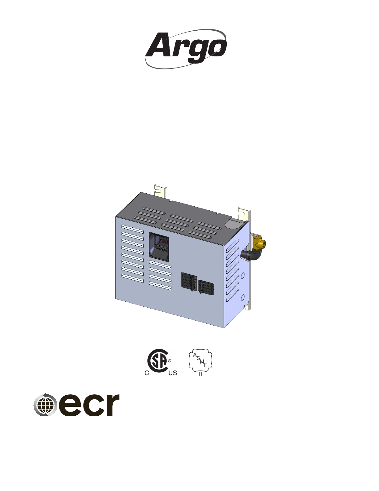
"AT" SERIES ELECTRIC
HOT WATER BOILERS
FOR FORCED HOT WATER
INSTALLATION, OPER ATION
& MAINTENANCE MANUAL
An ISO 9001-2008 Certied Company
Manufactured by:
ECR International, Inc.
2201 Dwyer Avenue, Utica NY 13501
web site: www.ecrinternational.com
Information and specications outlined in this manual in effect at the
time of printing of this manual. ECR International, Inc. reserves the
right to discontinue, change specications or system design at any
time without notice and without incurring any obligation, whatsoever.
P/N# 240009740, Rev. A [09/2013]
Page 2

TABLE OF CONTENTS
"AT" Series Boiler Dimensions .............................................................................3
Important Safety Information .............................................................................4
Introduction ........................................................................................................5
Voltage Rating Tables ..........................................................................................6
Locating The Boiler ..............................................................................................7
Hydronic Piping ...................................................................................................8
Electrical Connections .......................................................................................10
Sequence Of Operation ...................................................................................... 13
Control Operation .............................................................................................. 16
Wiring Diagrams ...............................................................................................19
Startup And Seasonal Maintenance ...................................................................21
General Maintenance .........................................................................................22
Additional Wiring Diagrams ............................................................................... 23
Modular Boiler Piping ........................................................................................ 26
Troubleshooting ................................................................................................27
Resistance Vs. Temperature Table .....................................................................30
Parts List - 2 & 4 Element Boiler ........................................................................ 32
Homeowner's Reference Table .......................................................................... 36
2
Page 3
C
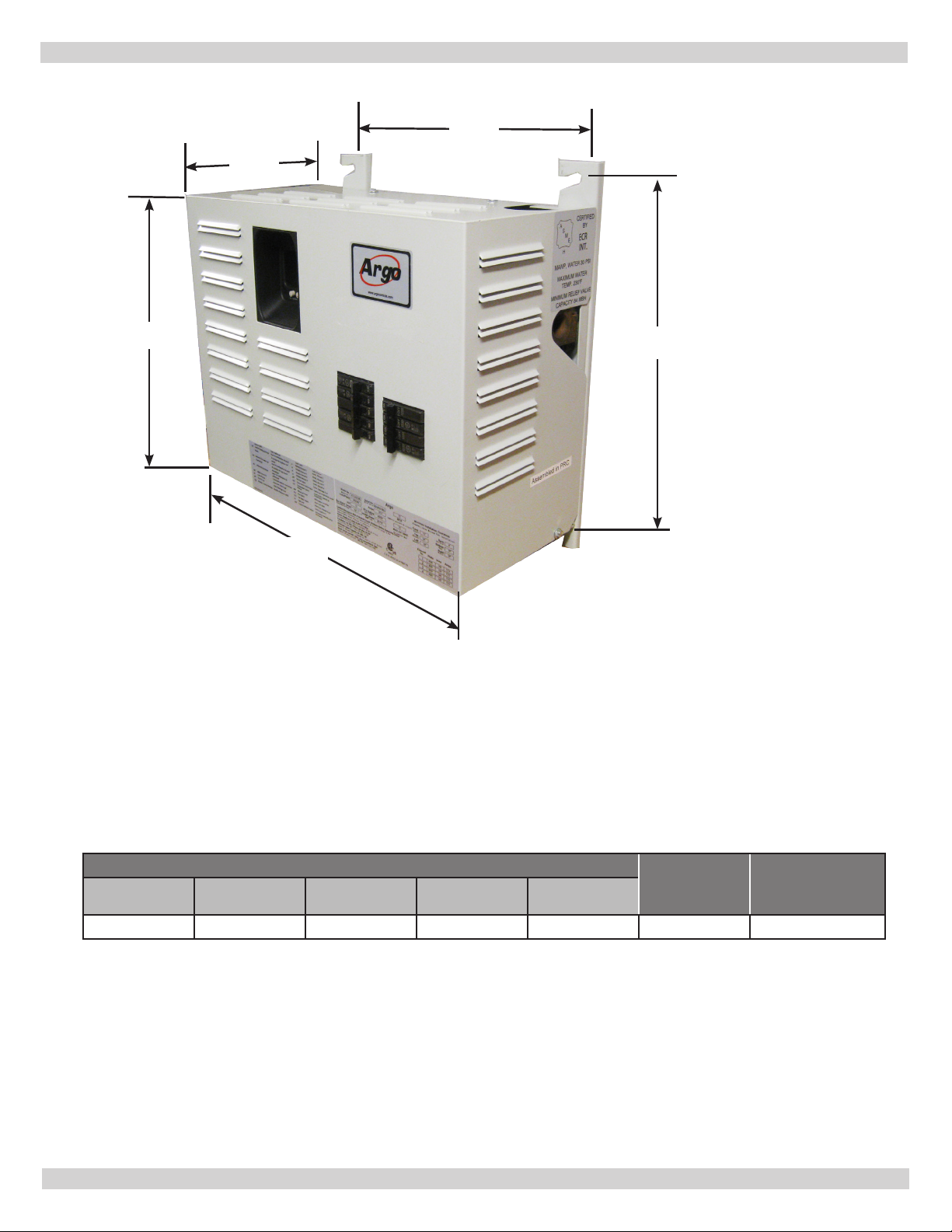
"AT" SERIES BOILER DIMENSIONS
D
A
E
B
Dimensions Inlet &
A B C D E
14⅝” 18⅝ “ 9¹/₃₂” 14⅜” 16¹⁵/₃₂” 1¼ NPT 70 lbs.
3
Outlet Pipe
Size
Approximate
Shipping Wt.
Page 4
IMPORTANT SAFETY INFORMATION
General
Boiler installation shall be completed by qualied agency.
WARNING
!
Fire, explosion, asphyxiation and electrical shock
hazard. Improper installation could result in death
or serious injury. Read this manual and understand
all requirements before beginning installation.
Keep this manual near boiler
Retain for future reference
Become familiar with symbols identifying potential
hazards.
Installation shall conform to requirements of
authority having jurisdiction or in absence of such
requirements:
•
United States
• National Electrical Code, NFPA 70.
• Canada
• Canadian Electrical Code, Part I, Safety Standard for
Electrical Installations, CSA C22.1
Where required by authority having jurisdiction,
installation shall conform to Standard for Controls
and Safety Devices for Automatically Fired Boilers,
ANSI/ASME CSD-1.
Additional manual reset low water cutoff may be required.
Requirements for Commonwealth of
Massa chusetts:
Boiler installation must conform to Commonwealth of
Massachusetts code 248 CMR which includes but is not
limited to: Installation by licensed plumber or gas tter.
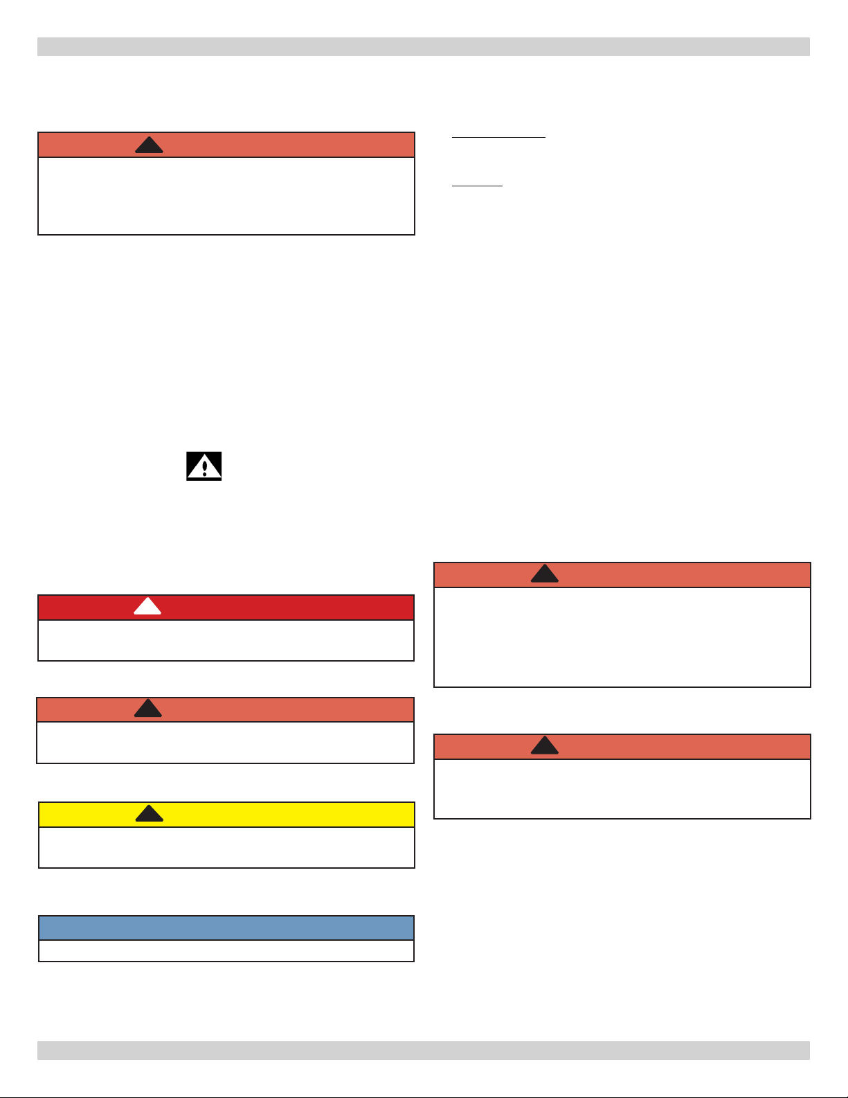
This is the safety alert symbol. Symbol alerts you to
potential personal injury hazards. Obey all safety messages
following this symbol to avoid possible injury or death.
!
DANGER
Indicates a hazardous situation which, if not avoided,
WILL result in death or serious injury
!
WARNING
Indicates a hazardous situation which, if not avoided,
could result in death or serious injury.
!
CAUTION
Indicates a hazardous situation which, if not avoided,
could result in minor or moderate injury.
!
WARNING
Keep boiler area clear and free from combustible
materials, gasoline and other ammable vapors and
liquids. Do not obstruct air openings to boiler room.
Failure to follow these instructions could result in
death or serious injury.
!
WARNING
Modication, substitution or elimination of factory
equipped or supplied or specied components could
result in death or serious injury.
NOTICE
Used to address practices not related to personal injury.
4
Page 5

INTRODUCTION
Introduction
• Boiler sizing is crucial. Calculate the maximum hourly
heat loss for each heated space in accordance with
procedures describes in The Hydronics Institute manual
H-22 (Heat Loss Calculation Guide), or method suitable
for local conditions, provided results are in agreement.
• Select appropriate boiler based on accurate heat loss
calculation.
• Do not oversize boiler, sizing is critical for in-oor
radiant heat applications.
• This manual is intended to familiarize installer and user
of Electric Hydronic Block with its installation, operation
and maintenance to assure its normal trouble free
operation.
• Argo electric boilers are designed and manufactured
with quality components for maximum life, durability
and minimum service. Follow installation instructions
carefully before operating heating system for optimum
efciency and satisfaction.
Unpacking
• Remove packaging and inspect unit for damage or
missing parts.
• Report any concealed damage or claims to carrier
immediately.
Standard Features
Control
• Three character LED display
• Three button User Interface
• Error code display
• Element Staging and Rotation
• Dual set points for comfort heating and domestic hot
water
• Setting for Fahrenheit or Centigrade temperature scales
• Water temperature heating range 90°-180°F (32-82°C)
• Dry re protection
• Connections for ow sensor and low water cutoff
• Load management control connection with auxiliary
heat source connection
• Freeze protection
• Circulator pump terminals
• 40VA transformer
• Three wire thermostat connection
• Audible alarm
• Pump exercising
• Relay contact monitoring
• Non-Volatile memory
Product Description
Electric Hydronic Block is heating device converts electrical
energy to heat energy through medium of water. Simplied
theory of this conversion is as follows:
Electrical Energy x Conversion Factor = Energy
– Or –
Kilowatts Of Electricity Used Per Hour x 3412 =
British Thermal Units (Btuh) Available Per Hour For
Heating.
• Information is basis used to establish Electric Hydronic
Block ratings (See Table 1 on page 4). Since conversion
process requires no combustion, boiler operates with
highest possible efciency.
• Electric Hydronic Block is constructed with cast iron
boiler that conforms to American Society of Mechanical
Engineers (ASME) Boiler & Pressure Vessel Code. Interior
design allows just enough water to be present for proper
heating element operation - no excess water is stored
which would cause undesirable thermal losses and longer
recovery times.
• Maximum Allowable Working Pressure Water (MAWP) 30 PSI.
• Control system is assembled in modular package keeping
overall size and weight of Electric Hydronic Block to
minimum. Construction of entire Electric Hydronic Block
conforms to Canadian Standards Association (CSA)
Standards for Safety for Electric Boilers.
Following important product information is located on
cabinet cover:
• Model Number
• Manufacturer's Serial Number
• BTU Rating
• Heating Element Ratings
• Water Pressure & Temperature Limits
• CSA Listing
• ASME Stamp
• Total Amps
• Clearance
• Argo Electric Boilers are controlled by electronic control
board maintaining water temperature. Control cycles
heating elements based on heating demand, and
preset boiler outlet water temperature. Control also
operates 120Vac circulating pump rated up to 5A. When
thermostat calls for heat, control will operate boiler to
regulate water temperature at pre-selected set point.
System pump is on whenever thermostat calls for heat.
• This product is not designed for aluminum wiring.
5
Page 6
VOLTAGE RATING TABLES
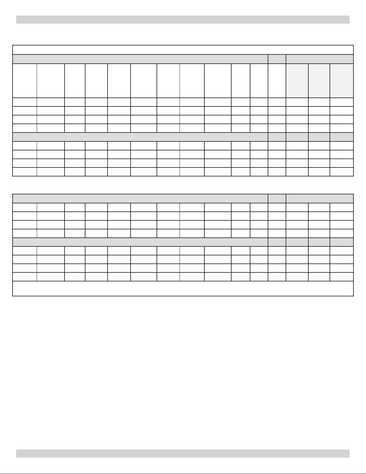
Table 1 -AT Boiler Electrical Specications
Operating at 240 Vac
INSTALLATION MANUAL AND OPERATING
INSTRUCTIONS
“AT” Series - 2 Element Boiler *Recommended Wire
Model
AT0623 6 240 6,000 20,500 25.0 3,000 2 6 31.0 38.8 40.0 8 8 10
AT0824 8 240 8,000 27,300 33.3 4,000 2 6 39.3 49.2 50.0 6 8 8
AT1025 10 240 10,000 34,100 41.7 5,000 2 6 47.7 59.6 60.0 4 6 6
AT1226 12 240 12,000 41,000 50.0 6,000 2 6 56.0 70.0 70.0 4 4 6
Boiler Size
Nominal
kW
Voltage
(AC)
Output
Power
(Watts)
Output
Power
BTU/Hr.
Amperage
Element
Size
(Watts)
at
240Vac
Number
Elements
Accessory
Load (A)
Total
Amps
MCA MOP
60°C
(140ºF)
AWG
75°C
(167ºF)
AWG
90°C
(194ºF)
AWG
“AT” Series - 4 Element Boiler
AT1243 12 240 12,000 41,000 50.0 3,000 4 6 56.0 70.0 70.0 4 4 6
AT1644 16 240 16,000 54,600 66.7 4,000 4 6 72.7 90.8 100.0 2 3 4
AT2045 20 240 20,000 68,200 83.3 5,000 4 6 89.3 111.7 125.0 1/0 2 2
AT2446 24 240 24,000 82,000 100.0 6,000 4 6 106.0 132.5 150.0 2/0 1/0 1
Operating at 208 Vac
“AT” Series - 2 Element Boiler
AT0623 6 208 4,507 15,400 21.7 3,000 2 6 27.7 34.6 35.0 8 10 10
AT0824 8 208 6,009 20,500 28.9 4,000 2 6 34.9 43.6 45.0 6 8 8
AT1025 10 208 7,511 25,600 36.1 5,000 2 6 42.1 52.6 60.0 6 6 8
AT1226 12 208 9,013 30,800 43.3 6,000 2 6 49.3 61.7 70.0 4 6 6
“AT” Series - 4 Element Boiler
AT1243 12 208 9,013 30,800 43.3 3,000 4 6 49.3 61.7 70.0 4 6 6
AT1644 16 208 12,018 41,000 57.8 4,000 4 6 63.8 79.7 80.0 3 4 4
AT2045 20 208 15,200 51,200 72.2 5,000 4 6 78.2 97.8 100.0 1 3 3
AT2446 24 208 18,027 61,600 86.7 6,000 4 6 92.7 115.8 125.0 1/0 1 2
MCA = Minimum Circuit Ampacity
MOP = Maximum Over-current protection
*Recommended Wire
*Recommended Field Wire Size per NEC Table 310.16
Not more than three (3) current carrying conductors in raceway
Based on ambient temperature of 30ºC (86ºF). Other ambient temperatures see NEC or CEC for correction factors.
Use Copper conductors only.
Recommended use only Class B or C type wire (see Table B).
Check with latest version of NEC and local codes.
UL-834, Section 14.2
Assuming 60ºC (140ºF) wire will be used for connections to boiler rated at 80 amperes or less, and 75ºC (167ºF) wire will
be used with boiler rated at more than 80 amperes.
6
Page 7
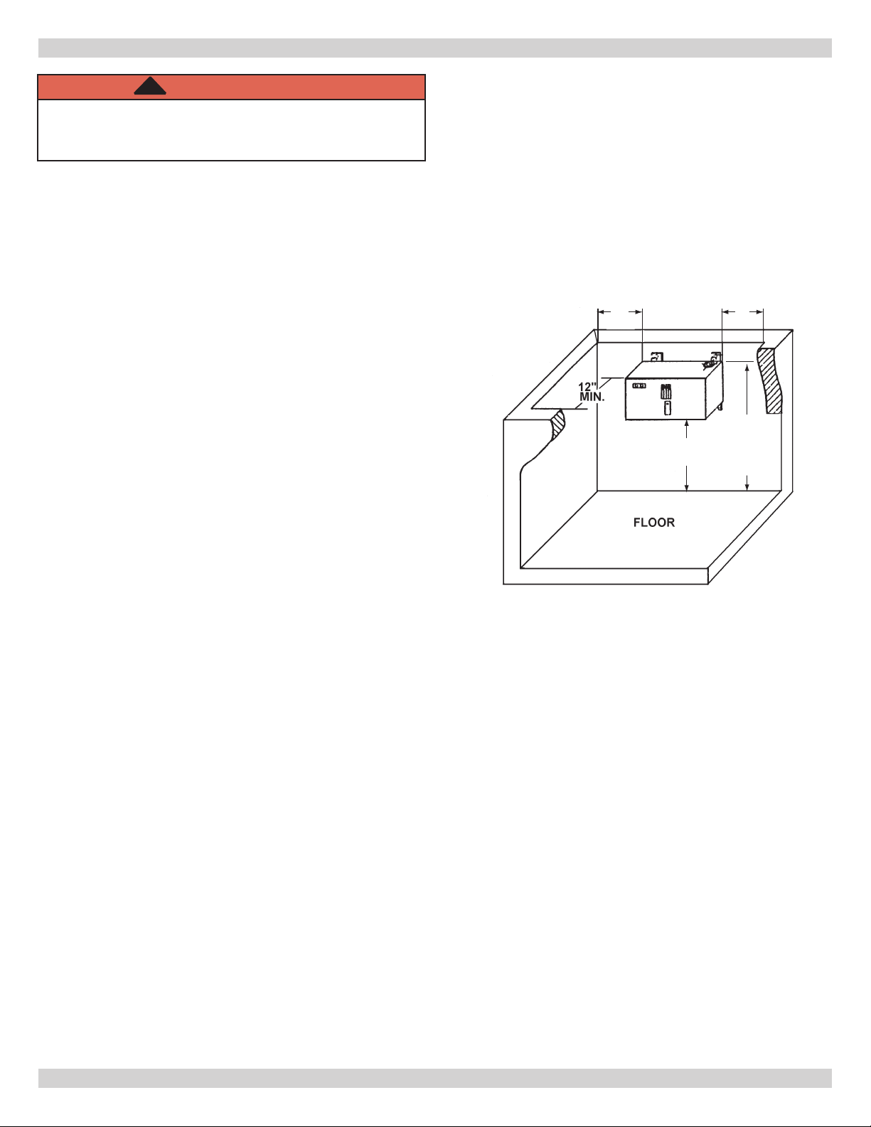
LOCATING THE BOILER
20”
MIN
20”
MIN
10”
MIN
5’-3”
SUGGESTED
HEIGHT FOR
EASE OF
INSTALLATION
!
WARNING
Electrical shock hazard. Do not install boiler under
water source. Failure to do so could result in death
or serious injury.
1.
Boiler is intended for indoor installation only and not
subject to water spray or leakage.
2.
Electric Hydronic Block units are intended to be wall
mounted and provided with mounting brackets for wall
mounting. Use of lag screws or anchor bolts through
holes provided, or on 3/4" plywood panel. On uneven
walls, suggest mounting surface be provided such as
two 2 x 4’s.
3.
Mount surface of Electric Hydronic Block, no closer
than 20 inches to wall surface on left and 20 inches
minimum to wall surface on right or more, depending
on plumbing. Minimum top clearance 16 inches, bottom
10 inches. Allow sufcient room from front of unit
to door or wall to remove cover - at least 12 inches
minimum.
4.
Install unit with minimum clearance from top of unit
to ceiling of 16 inches. If minimum requirements of
space are used, suggested enclosure be exposed to
means of ventilation. Electric Hydronic Block unit must
be mounted level, using top of back plate as leveling
point.
5.
When installed in utility room, door should be wide
enough to allow largest boiler part to enter, or to
permit replacement of another appliance such as water
heater.
6.
Boiler room should be well vented and temperature
maintained between 45-80°F (7-26.5°C).
Minimum clearances to combustible constructions
are:
TOP ........................................................... 16 IN.
FRONT ...................................................... 12 IN.
LEFT SIDE................................................. 20 IN.
RIGHT SIDE .............................................. 20 IN.
REAR ........................................................... 0 IN.
BOTTOM....................................................10 IN.
BOILER LOCATION & CLEARANCE DIMENSIONS
NOTE: Greater clearances for access should supercede
re protection clearance.
7
Page 8
HYDRONIC PIPING
WARNING
!
Fire, explosion, asphyxiation, burn, scald and
electrical shock hazard. System design must
incorporate primary/secondary piping to allow boiler
pump to prepurge and post purge the unit before
and after energizing the heating element. Shortened
element life and/or opening of safety relief valve
could occur. Failure to follow these instructions could
result in death or serious injury.
Circulating System
• Design system as primary/secondary piping. Operate
system with maximum output temperature of 180ºF
(82°C) or lower and temperature rise across the unit of
20ºF (11°C) or lower. Refer to tables below and Figures
2 & 3.
• Return water temperature must be higher than room
temperature in which boiler is installed to prevent
condensation.
“AT” Series - 2 Element Boiler
KW Capacity Minimum Flow Rate (GPM)*
6 2.0
8 2.7
10 3.4
12 4.1
5.
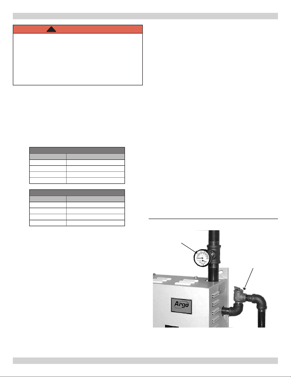
Outlet or supply pipe line to radiation is located at top
of unit. Combination temperature pressure (altitude)
gauge is provided with each unit and should be
installed close to boiler outlet. It is important the gauge
sensor be completely immersed in owing water to
assure correct temperature readings.
6.
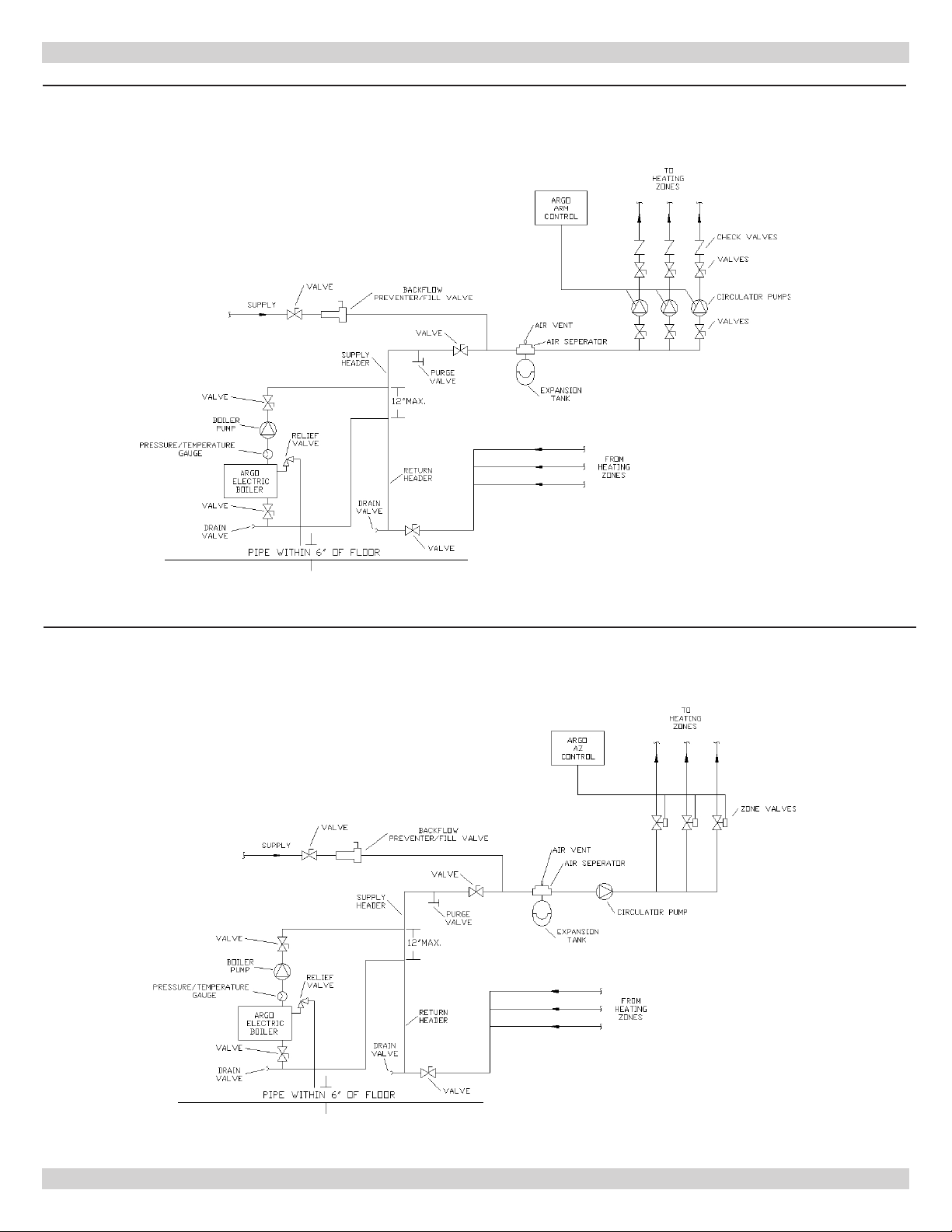
Install gate valves at locations shown in Figures 2 &
3, so any boiler servicing requiring removal of water
can be done quickly and easily. Not illustrated but
recommended is installation of air vents at high points
of hydronic system to reduce initial start up time and
help avoid element burnout during entire life of heating
system.
7.
Safety relief valve is supplied with each Electric
Hydronic Block and must be installed vertically. Install
at location and discharge direction shown using pipe
nipple and elbow supplied. See Figure 1. Add piping so
any water discharged will not damage boiler or other
system components.
8.
For further piping information refer to Hydronics
Institute (AHRI) manual (Installation Guide
for Residential Hydronics).
9.
Pipe the discharge outlet of the safety relief valve
within 6" of the oor.
“AT” Series - 4 Element Boiler
KW Capacity Minimum Flow Rate (GPM)*
12 4.1
16 5.5
20 6.8
24 8.2
* Flow rate based on 20°ΔT
Connecting Supply And Return Piping
1.
Hot water boilers installed above radiation level must
be provided with low water cutoff device either as part
of boiler or at time of boiler installation.
2.
When boiler is connected to heating system utilizing
multiple zone circulators, each circulator must be
supplied with ow control valve to prevent gravity
circulation.
3.
Reduced pressure back ow preventer must be present
under provisions required by Environmental Protection
Agency, (EPA).
4.
Manufacturer requires plumbing arrangements as
illustrated in Figures 2 & 3. Inlet or return pipe is
located at bottom of unit. Reverse ow will result in
noisy operation and cause very early element failure.
Drain cock is to be located at lowest point of piping.
Figure 1 - Safety Relief Valve
Pressure
Gauge
Safety Relief
Valve
8
Page 9
HYDRONIC PIPING
Figure 2 - Primary/Secondary Piping for Multiple Zoning with Circulators
Figure 3 - Primary/Secondary Piping For Multiple Zoning With Zone Valves
9
Page 10
ELECTRICAL CONNECTIONS
Boiler Wiring
NOTICE
Boiler is not designed for use of aluminum wiring.
Boiler failure can occur if aluminum wiring is used.
1.
Argo Electric Hydronic Boilers are pre-wired for use
with 240-volt, 3 wire, single-phase, 50/60-hertz power.
For reduction in boiler capacity when line voltage is less
than 240 volts see Table 1 page 6.
2.
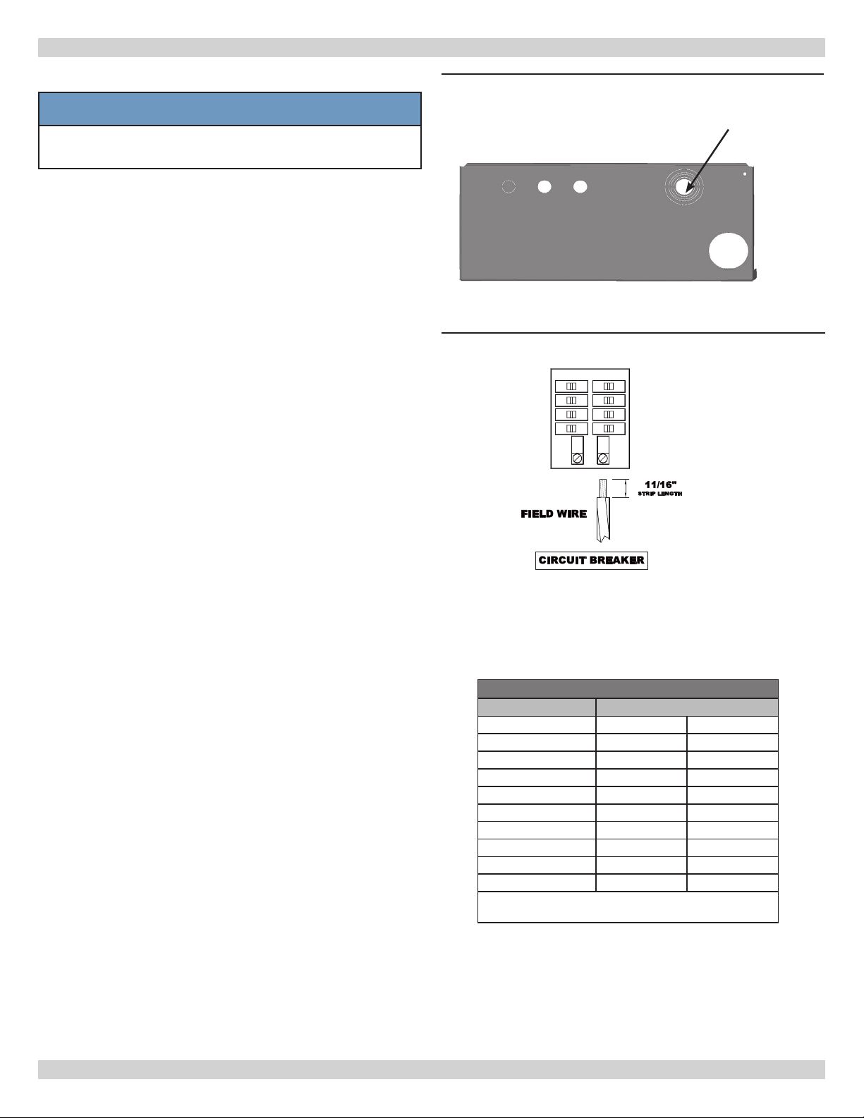
Opening provided in jacket bottom panel for eld wiring,
refer to rating chart for recommended wire sizes. See
Figure 4 for stepped Electrical Knock-out.
3.
Electrical wiring shall be in accordance with
requirements of authority having jurisdiction. Refer to:
• Canada - Canadian Electrical Code, CSA C22.1 Part 1,
Safety Standards for Electrical Installations.
• USA - National Electrical code, ANSI/NFPA 70.
4.
Verify nameplate rating and check related codes to
properly size conductors, switches and over current
protection.
5.
Stepped knockout is provided on bottom of cabinet for
different voltage connections. Wire connections refer
Figures 8 and 9 or wiring diagram on inside of boiler
front cover.
6.
All circuit breakers or disconnects ahead of boiler must
be OFF. Turn boiler integral breakers off at this time as
well. Remove boiler front cover by removing 4 screws
from top and sides.
7.
Boilers used in multiple zone system, zone valves
must be powered from independent source and have
electrically isolated end switches or isolating relays
wired in parallel to boiler thermostat terminals. Do not
attempt to power zone valves from transformer in
boiler control system.
Field Wiring
• All Field wiring shall be in accordance with NEC or CEC
standards.
• Minimum Circuit Ampacity (MCA) and recommended
Maximum Over-current Protection (MOP) are listed on
nameplate of unit, see Table 1.
• Use Copper conductors only.
• Use only Class B or C Stranded wire. See Table 2.
• Wire Strip Length: 11/16” (Minimum). See eld wiring
diagram. See Figures 9 and 10.
• Wire must be fully inserted into terminal block.
Figure 4 - Stepped Electrical Knock-outs -
Jacket Bottom
Field Wiring
Entrance
Figure 5 - Field Wiring Diagram
Wire Classes - Table 2
Number of Concentric Strands
Wire Size AWG Class B Class C
10 7 19
8 7 19
6 7 19
4 7 19
3 7 19
2 7 19
1 19 37
1/0 19 37
2/0 19 37
Class B - Power cables
Class C - Power cables where more exibility is desired
• Field terminal wire lugs shall be securely tightened.
• Do not use wire grease on wire termination
connections. This will change torque properties.
10
Page 11
ELECTRICAL CONNECTIONS
Field Wiring - Continued
Limit Control Operation
1.
MAIN POWER SUPPLY: Depending on model
designation, the electric Hydronic Block may be
energized by alternating current service entrances: 240
volt single phase 50 or 60 cycle 3 wire plus ground.
Wire size see Table 1. Sizes listed for various capacity
units include total amperes necessary to operate
elements, circulator and zone valves where used. Wire
sizes specied conform to Canadian Electrical Code
(Canada) or National Electric Code (USA) and include
derating for ampacity and temperature. Use copper
wire only. Check state and local requirements.
A. Read data name plate before connecting unit.
Electrical connections are provided and located for
proper installation.
B. Use only copper wire of proper size and make sure
all terminations are tight. Do not use aluminum
wire.
2.
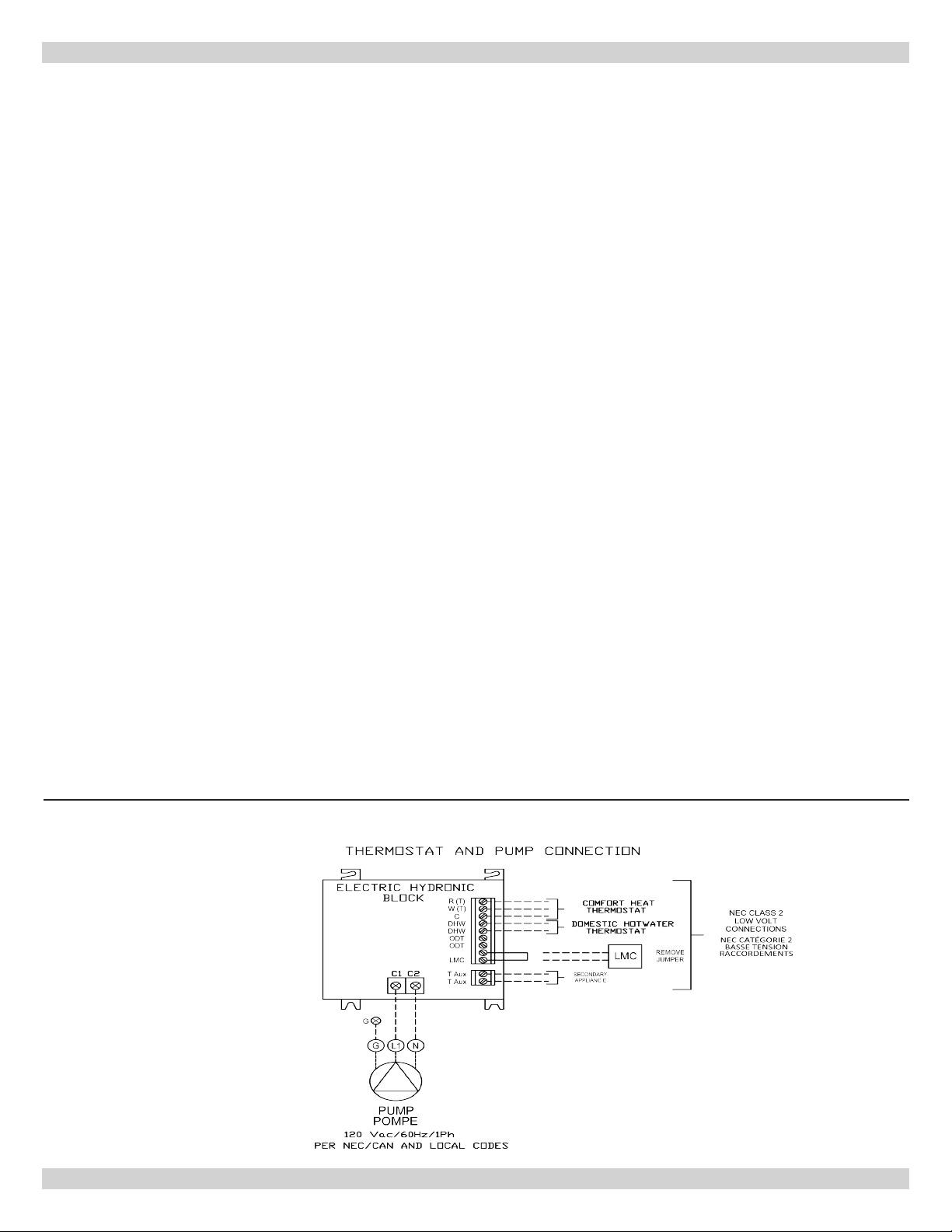
CIRCULATOR POWER SUPPLY: Terminals identied
as C1(L) and C2(N) at bottom of control panel (Figure
6) shall be used to supply one circulator pump
power. Circulator motor shall not be larger than 1/6
horsepower with maximum 5.0 amp rating. Wiring from
control panel to the pump should have insulation rated
75°C. Circuit protection is provided by 15 amp breaker
on boiler.
Note: Argo AT Boiler will work with standard and
programmable setback thermostats.
Thermostat Installation
1.
Install thermostat on inside wall ve feet above oor.
2.
NEVER install thermostat on outside wall.
3.
Do not install thermostat where it will be affected by
sunlight, drafts, televisions, lighting xtures, hot or
cold pipes, replaces, or chimneys.
4.
Instructions for nal adjustment of thermostat
(adjusting heating anticipator, calibration, etc.) are
packaged with thermostat.
5.
Recommended setting for heating anticipator is
0.1 amps.
Wiring On Control
• PUMP: Connect only 120 Vac 1/6 hp (maximum) pump
to terminals C1(L) and C2(N) on controller. Ground
screw is located on control panel. Strip wire ends before
inserting into terminal block. Tighten terminal screws.
Do not use pump rated greater than 5 amps!!
• THERMOSTAT: Two or three wire thermostat capable.
Terminals R(T), W(T) and C are provided. Two wire
thermostat use R(T) and W(T). Three wire thermostat
also use terminal C. See Figure 6. Do not apply
external power source to terminals!! Strip wire ends
before inserting into terminal block. Tighten terminal
screw clamps.
NOTE: If circulator pump is larger than maximum size
listed above, separate circulator pump relay must be
provided with separate overload protection. Where more
than one circulator is used for zoning, it must be installed
and protected according to approved electrical codes.
Figure 6 - Thermostat and Pump Connection
11
Page 12
ELECTRICAL CONNECTIONS
Low Volt Connections
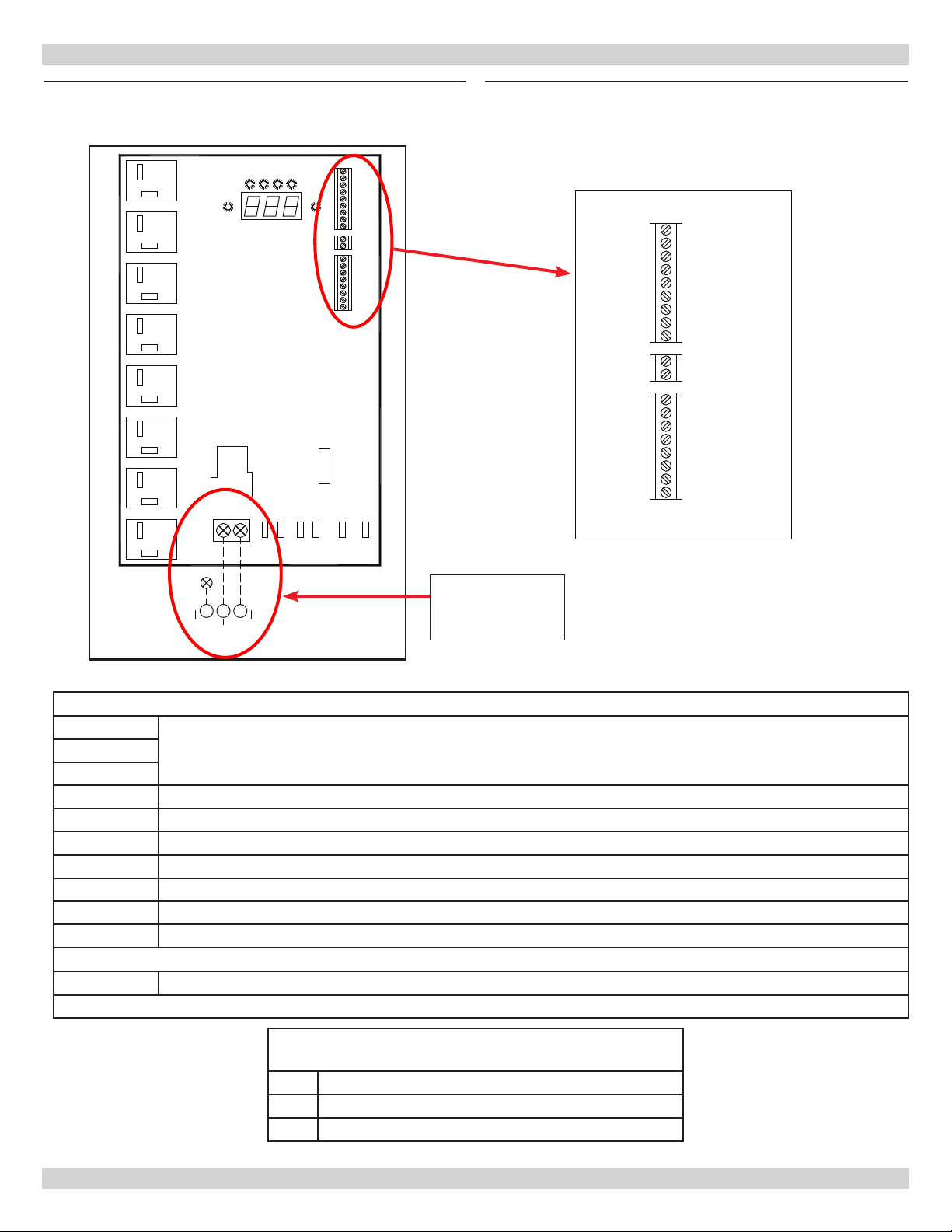
Figure 7 - Wiring on Control Board Figure 8 - Low Voltage Wiring on Control Board
ELEMENT 1
ÉLÉMENT 1
DEMAND
DEMANDE
ELEMENT 2
ÉLÉMENT 2
CIRCUIT DU TABLEAU
ELEMENT 3
ÉLÉMENT 3
ELEMENT 4
ÉLÉMENT 4
C1 C2
G
G N
L1
PUMP
POMPE
ELEMENTS
ÉLÉMENTS
PUMP
POMPE
CONTROL
BOARD
DE COMMANDE
N N L
R (T)
W (T)
C
DHW
DHW
ODT
ODT
LMC
LMC
T Aux
T Aux
HL
HL
FLO
FLO
LWC
LWC
WT
WT
5A
FUSE
FUSIBLE
24
VAC
COM
L
R (T)
W (T)
C
DHW
DHW
ODT
ODT
LMC
LMC
T Aux
T Aux
HL
HL
FLO
FLO
LWC
LWC
WT
WT
System Pump
Connection
Control Inputs (NEC Class-2 Low Voltage)
R (T)
W (T)
C
DHW Domestic Hot Water – Thermostat Input. Dry Contact Close Activation DHW – DHW
ODT Not Used
*LMC Load Management Control Input. Dry Contact Normally Close LMC – LMC
HL High Limit Input (Factory Installed)
*FLO Flow Switch Input – Installer Supplied. Dry Contact Normally Close FLO – FLO
*LWC Low Water Cutoff Input – Installer Supplied. Dry Contact Normally Closed LWC –LWC
WT Water Temperature Sensor Input (Factory Installed)
Control Output (NEC Class-2 Low Voltage)
T Aux Auxiliary Heating Appliance Thermostat Connection
*Factory Jumper Installed
Comfort Heating – Thermostat Input (R W C) or zone valve end switch (R W), Dry Contact Close R-W Activation,
24Vac R-C
System Pump Connection (120Vac 60Hz, 1ph, 5A
1/6 hp Max)
C1 Pump Hot (L1)
C2 Pump Neutral (N)
G Pump Ground (G)
12
Page 13
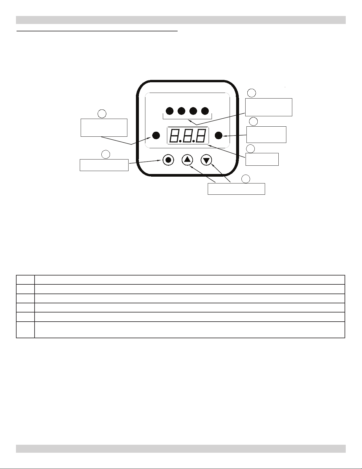
Figure 8A - AT Boiler Controller
SEQUENCE OF OPERATION
2
HEATING DEMAND
LED INDICATOR
(GREEN)
1
MODE AND POWER
SELECTION BUTTON
HEATING ELEMENTS
1 2 3 4
DEMAND
MODE/PWR UP DOWN
3
HEATING ELEMENT
LED INDICATORS
4
PUMP
LED INDICATOR
(GREEN)
5
LED DISPLAY
(RED)
6
UP AND DOWN
ADJUSTMENT BUTTONS
(GREEN)
PUMP
1 Mode and Power Selection Button - Turns the boiler on and off, selects mode and conguration settings
2 Heating Demand LED Indicator – Energized when there is call for comfort heating or domestic hot water
3 Heating element LED Indicators – Energized with corresponding heating element
4 Pump LED Indicator – Energized with boiler pump relay
5 LED Display – Indicates water temperature, set point, mode, and error codes
Up and Down Adjustment Buttons – Used to select temperature set point for comfort heating, domestic hot water
6
and conguration selections
13
Page 14
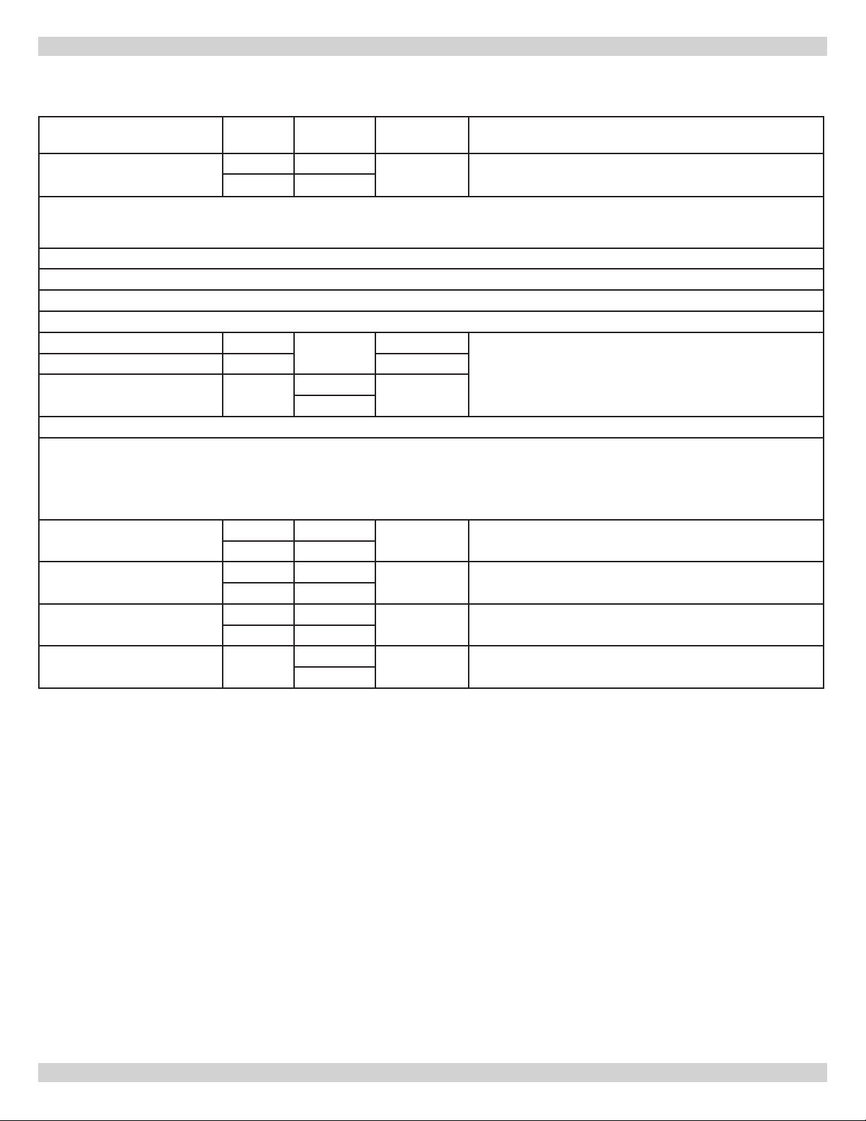
Setting the AT Boiler Controller
SEQUENCE OF OPERATION
User Settings Display Possible
Value
On/Off Mode ON ON
OFF OFF
Note: When electrical power has been removed and re-applied, when the unit is turned on it will automatically enter a dry re test
mode (If dFt is on, see Conguration). The display will ash dFt. To bypass the test, Press and hold Up ▲ and Down ▼ arrow buttons
for 2 seconds.
To access the following: Unit must be in the “ON” Mode. Press the MODE/PWR button to select setting.
Press the up ▲ or down ▼ arrow buttons to change setting.
Press the MODE/PWR button to save setting. Display will ash three times to conrm setting is saved
Automatically exits and saves after 5 seconds.
CHS – Comfort Heating CHS
DHW – Domestic Hot Water dHW 170°F
DFS – Differential Setting
Conguration Settings
To Access: Unit must be in the “OFF” Mode. Press and hold Up ▲ and Down ▼ arrow buttons for 10 seconds
Press the up or down arrow button to choose selection.
Press the MODE/PWR button to enter the selection. Press the Up ▲ or Down ▼ arrow button to change the setting.
Press MODE/PWR button so save selection.
To Exit: Press and hold Up ▲ and Down ▼ arrow buttons for 2 seconds. Automatically saves setting and exits after 60 seconds.
DEG – Temperature Scale C C
STG – Number of Heater
Elements
EL – Active Elements 1-2 1-2
DFT – Dry Fire Test Active/
Inactive
dFS
F F
2 2
4 4
3-4 3-4
ON/OFF On
90-180°F
32-82°C
4-20°F
2-11°C
OFF
Factory
Setting
OFF
150°F Press the MODE/PWR button to select setting. Press the
10°F
F
2 or 4
1-2
On
Press and hold the MODE/PWR button for 2 seconds to turn
the unit On or Off.
up ▲ or down ▼ arrow buttons to change setting. Hold the
button to scroll rapidly.
Press the Up ▲ or Down ▼ arrow buttons to change
setting.
Press the Up ▲ or Down ▼ arrow buttons to change
setting.
Available only if STG is 2. Press the Press the Up ▲ or
Down ▼ arrow buttons to change setting.
Press the Up ▲ or Down ▼ arrow buttons to change setting
Overview
14
Page 15
SEQUENCE OF OPERATION
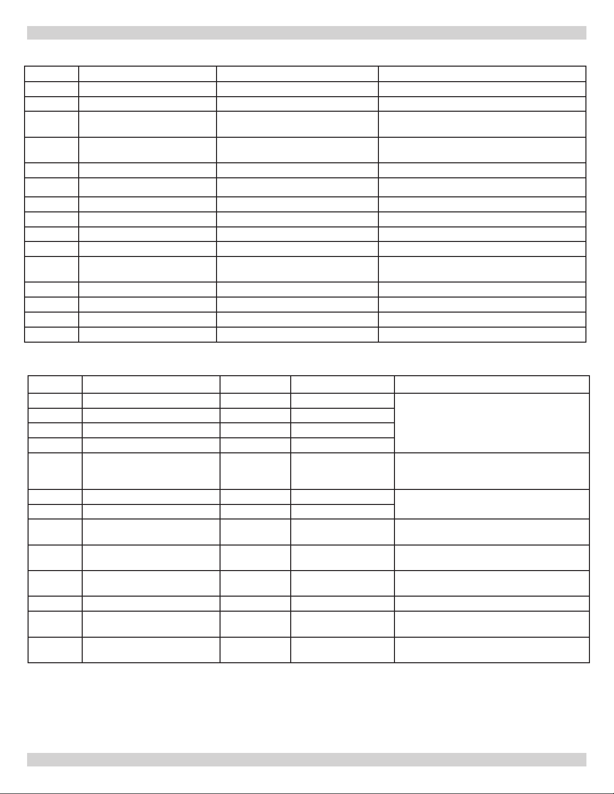
Boiler Display Codes
Display Description Range Note
On Boiler in On mode
Off Boiler in Off mode
CHS
dHS
dFS Differential Setting 4-20°F (2-11°C) Applies to CHS & dHS
DEG Degrees Temperature scale F or C
Stg Heating Element Stages 2 or 4
EL Active Elements 1-2 or 3-4 Only available if Stg is 2
dFt Dry Fire Test Displayed when power initially applied
LdC
F Degrees Fahrenheit
C Degrees Centigrade
1-2 Elements 1 & 2 Active Two element boiler only
3-4 Elements 3 & 4 Active Two element boiler only
Comfort Heating Setting 90-180°F (32-82°C) Control prevents setting from being higher than
Domestic Hot Water Setting
Domestic Hot Water Setting 90-180°F (32-82°C) Control prevents setting from being lower than
Comfort Heating Setting
Load Management Displayed when LMC terminals open De-activates heating elements. Diverts TT to
TTAux for secondary appliance.
Fault Codes
Display Failure Alarm Boiler state Action Required
r1 Element-1 relay failure Audible Alarm ON Check all circuit breakers. Reset power
r2 Element-2 relay failure Audible Alarm ON
r3 Element-3 relay failure Audible Alarm ON
r4 Element-4 relay failure Audible Alarm ON
Dry Fire Failure Audible
dFF
tSO Temperature sensor open Audible Alarm ON Replace temperature sensor
tSS Temperature sensor shorted Audible Alarm ON
AbP
FLO
LCO
HL High limit(s) Audible Alarm High Limit(s) Open Reset power, Call for service
CHF
FP
Abnormal Power Audible Alarm Control voltage outside
Flow Switch Open Audible Alarm Flow switch open
Low Water Cutoff Open Audible Alarm Low Water Cutoff open
Control Hardware Audible Alarm Control Hardware
Freeze Protection No Audible
Alarm after 3
attempts
Alarm
ON Correct fault, reset power
the range of 18-30Vac
(Installer item)
(Installer item)
Failure
Water temperature
below 45°F (27°C)
by cycling pump circuit breaker (15A) or
pressing and holding MODE/PWR button for 2
seconds. Call for service if problem persists.
Verify all circuit breakers are on. Call for
service if problem persists
Check water ow
Check water level
Call For Service
Control energizes pump and heating mode
until WT reaches 55°F.
15
Page 16
CONTROL OPERATION
Initial Start Up
When electrical power is applied to AT boiler the control
displays rmware revision code. It will then revert to mode
it was in prior to power loss (factory setting is OFF mode).
Pressing MODE/PWR button for 2 seconds, unit will enter
ON mode. Pressing MODE/PWR button again for 2 seconds
will return unit to OFF mode. Once in ON mode the control
automatically begins a Dry Fire Test (if DFt is set to Y in the
conguration) where pump is energized and rst element
is pulsed. (see Dry Fire Test Mode). Dry Fire Test is only
initiated after power loss. To by-pass Dry Fire Test Mode
and enter heating mode, press ▲up and ▼down arrow
buttons for 2 seconds.
Two Temperature Operation
AT boiler is designed to control two loads with independent
temperature control such as a comfort heating zone
(CHS) and indirect domestic hot water tank (DHS). Other
applications include in-oor radiant system with n tube
baseboard system.
Setting Water Temperature
To set boiler water temperature, place boiler in on mode
and then select temperature setting mode by pressing
MODE/PWR button. Use ▲up or ▼down arrow buttons to
set temperatures for comfort heating “CHS”, domestic hot
water setting “dHS” and differential setting “dFS”.
During heating operation the safety circuit is monitored.
If no faults exist the rst element will energize and rate of
water temperature rise is calculated.
Control will energize elements in sequence based on
temperature rise of water and target time of 5 minutes
to reach setpoint. Minimum on an off times apply to each
element.
When water temperature approaches setpoint temperature
heating elements will de-energize to prevent water
temperature from exceeding setpoint temperature. When
water temperature reaches set point all remaining heating
elements will de-energize. Control will then cycle elements
on and off to maintain set point temperature. At start
of each subsequent heating cycle the lead element to
energize will rotate to allow for even duty cycle time over
all elements.
Pump will remain energized while there is call for heat
(TT or DHW-TT closed). When call for heat is satised unit
enters post purge period. Pump shall remain energized
for 3 minutes starting at point in which last element deenergized.
Rate which elements energize and de-energize to maintain
water temperature can be adjusted. Differential setting
is used to determine point which heating elements are
energized or de-energized. Increasing differential setting
will de-energize heating elements sooner and reduce
potential for temperature overshoot. A larger differential
will also reduce cycles per hour of the boiler.
NOTICE
Setting for CHS cannot exceed setting for DHW. Setting
for DHW cannot be set below setting for CHS.
Decreasing differential setting will keep heating elements
on longer and allows for tighter set point control increasing
potential for temperature overshoot. A small differential
also increases boiler cycles per hour.
Heating Operation Sequence
To begin heating sequence control board must be “On” for
boiler operation. All safety inputs must be closed (HL, LWC,
FLO) as well as Load Management Control (LMC) terminals.
Setpoint temperature for either CHS or dHS must be above
current water temperature.
To start boiler heating sequence the thermostat or pump
end switch will close the connection between terminals
[Comfort heat - R & W (T & T)] or [Domestic hot water DHW_T&T] on the control. Pump relay energizes for 30
seconds prior to electric elements while a check of safety
circuit and water temperature is conducted. (Note Flow and
LWCO circuits check is conducted after the pump starts,
since water ow and water level are dependent on pump
being energized). If heating load is satised by residual
heat in the boiler during 30 second pre-purge period the
elements will not energize. Heating element(s) will begin
to energize after 30s pre-purge is complete.
LED’s for heating elements, pump status and heat call will
illuminate as each is energized. If safety circuit is open
elements will not energize and error code is displayed.
Starting point for differential setting is 10°F (5.5°C).
Depending on application, boiler size, number of heating
zones and whether or not there is domestic hot water
application, differential setting can be adjusted to
accommodate the installation.
Dry Fire Test
Dry Fire is not a substitute for a low water cutoff
sensor control.
Dry Fire Test detects presence or lack of water in the boiler
and prevent elements from energizing if dry condition exists.
Dry Fire Test Mode is initiated following power outage and
can take from 5 to 10 minutes to complete. Boiler must be
ON and conguration setting for dFt must be set to Y. During
Dry Fire Test pump is energized and rst heating element is
pulsed while temperature sensor is monitored to determine
if water is present in the boiler. If failure occurs, “DFF” is
displayed and a re-try takes place. After three consecutive
failures an audible alarm will sound and pump will stop.
Power must be removed and dry condition corrected to clear
fault code.
16
Page 17

CONTROL OPERATION
Once initiated, Dry Fire Test can be canceled by pressing
▲up and ▼down arrow buttons simultaneously for 2
seconds. This by-pass feature is intended for installer and
should only be used when it is clear that dry condition
does not exist. Dry Fire Test is selectable in conguration
mode and can be set to Y or N. To prevent Dry Fire testing
from automatically occurring, change setting for dFt to N in
conguration mode. Do not change setting unless special
circumstances exist with application where conducting of
Dry Fire Test does not accurately detect presents of water
in the boiler.
Load Management Control (LMC)
Load management (LMC) feature can be used to
temporarily de-activate the boiler and place it in stand-by
mode. Some utility companies use this feature during peak
demand periods to load trim the utility’s power grid.
Control is equipped with auxiliary set of contacts (T
Aux) which can be used to connect a secondary heating
appliance. While the load management terminals (LMC) are
open the heating elements are prevented from energizing
and “LdC” is displayed. The call for heat on TT or DHW
terminals is then diverted to the T Aux terminals to
energize a secondary heating appliance.
When LMC is open and TT or DHW_TT is closed, the pump
shall remain off accept for post purge mode.
LMC terminals on boiler are intended to be connected to
low volt, normally closed dry contacts of the utility LMC
unit. Do not connect power to LMC terminal.
To connect utility LMC system, rst remove jumper from
LMC terminals on AT boiler control, then connect LMC unit
to terminals.
The T aux terminals can be used to energize a secondary
appliance. T Aux terminals are low voltage, normally
open and will close when LMC terminals open and there is
heating call on either R(T)-W(T) or DHW terminals .
To connect a ow sensor rst remove the factory installed
jumper from the FLO terminals of the AT boiler control.
Then connect the alarm output, dry contact, normally
closed terminals of the ow sensor to the FLO terminals
of the AT boiler control. Do not connect power to the FLO
terminal.
Low Water Cutoff Sensor Input (LWCO)
Low Water Cutoff Sensor feature can be used to connect
an installer provided low water cutoff sensor to de-activate
the boiler if water is not present at the sensor (abnormal
condition).
The control is equipped with an auxiliary set of contacts
(LCO) which can be used to connect a low water cutoff
sensor. While the low water cutoff terminals (LCO) are open
the heating elements are prevented from energizing and
“LCO” is displayed. The sensor input is only active while the
control is attempting to energize heating element(s). The
low water cutoff sensor input IS NOT active during the pre
and post purge modes.
The LCO terminals on the boiler are intended to be
connected to low volt, normally closed dry contacts of the
water ow sensor.
To connect a low water cutoff sensor rst remove the
factory installed jumper from the LCO terminals of the AT
boiler control. Then connect the alarm output, dry contact,
normally closed terminals of the low water cutoff sensor to
the LCO terminals of the AT boiler control. Do not connect
power to the LCO terminal.
Anti-Short Cycle Timer, heating call satised
After the completion of a comfort heating or domestic hot
water cycle, the heating elements shall remain off for a
minimum of three (3) minutes. The ASCT time begins when
the last heating element de-energizes. The pump shall be
allowed to run during the ASCT period.
Flow Sensor Input (FLO)
Flow sensor feature can be used to connect an installer
provided water ow sensor to de-activate the boiler if water
is not owing through the boiler (abnormal condition).
The control is equipped with an auxiliary set of contacts
(FLO) which can be used to connect a water ow sensors.
While the ow sensor terminals (FLO) are open the heating
elements are prevented from energizing and “FLO” is
displayed. The sensor input is only active while the control
is attempting to energize heating element(s). The ow
sensor input IS NOT active during the pre and post purge
modes.
The FLO terminals on the boiler are intended to be
connected to low volt, normally closed dry contacts of the
water ow sensor.
17
Anti-Short Cycle Timer, water temperature satised
While a heating call exists (TT or DHW-TT closed) and an
element cycles off to maintain setpoint temperature, it will
not re-energize for 90 seconds.
Pump Exercising
After 24 hours of pump inactivity, the pump will turn on
for 60 seconds. Boiler must be in ON mode for pump
exercising to occur.
Non-Volatile Memory
If power is lost, after it is restored the unit will return to
the mode it was in prior to power loss. All user settings
shall be retained and restored.
Page 18

CONTROL OPERATION
Boiler Fault Codes
• Freeze Protection
If the water temperature falls below 45°F (7°C) the
control will automatically initiate a heat call sequence
RW (TT) until the water temperature reaches 55°F
(13°C). Boiler must be in ON mode for freeze protection
to occur.
• Relay Failure Alarm
If a heating element relay fails the control shall switch
off all heating elements and energize the pump. The
audible alarm shall sound and the relay designator,” r1”,”
r2”, “r3”, “r4” shall be displayed until the error clears
and the power is reset.
• Temperature Sensor Failure
The water temperature sensor shall be monitored at all
times, (on and off modes). If the sensor is open “tSO”
shall be displayed. If the sensor is shorted “tSS” shall
be displayed. In both cases the control shall switch off
all heating elements. The audible alarm shall sound for
a minimum of 30s and until the error clears and the unit
is reset with the MODE/PWR button or disconnecting the
main power.
• High Limit Alarm
The high limit alarm shall be monitored at all times
except while the LMC terminals are open.
If the High Limit switch opens the control shall switch
off all elements and enter a 60 second purge mode. The
audible alarm shall sound and “HL” shall be displayed for
a minimum of 30 seconds and until the error clears. The
pump shall remain on for a minimum of 30 seconds after
the fault clears.
• Control Hardware Failure
Control hardware monitoring system is active while
control is on. If control hardware failure is detected the
control shall switch off all appliances. The audible alarm
shall sound and “CHF” is displayed for minimum of 30
seconds and until error clears.
• Test Mode
Test mode is intended for installer verication of AT
Boiler control. It is used to reduce time required to
conduct comprehensive function test of the unit.
Initiation of test mode can be accessed through the user
interface and is not intended for unauthorized personal.
• Abnormal Power Alarm
The incoming power shall be monitored at all times, (on
and off modes). If the power to the control falls outside
the range of 18Vac - 30Vac the control shall switch off
all appliances. The audible alarm shall sound and “AbP”
shall be displayed for a minimum of 30 seconds and
until the error clears.
• Flow Alarm
The ow alarm shall only be monitored during
the heating cycle while elements are energized or
attempting to be energized. An open ow switch shall
have no effect while heating elements are off.
If ow switch opens while elements are energized or
attempting to be energized, control shall switch off all
elements and enter 60 second purge mode. The audible
alarm shall sound and “FLO” shall be displayed for
minimum of 30 seconds and until error clears or demand
for heat ceases. Pump shall remain on for minimum of
30 seconds after fault clears.
• Low Water Cutoff Alarm
The Low Water Cutoff alarm shall only be monitored
during the heating cycle while elements are energized or
attempting to be energized. An open Low Water Cutoff
shall have no effect while heating elements are off.
If Low Water Cutoff opens while elements are energized
or attempting to be energized, control shall switch off all
elements and enter 60 second purge mode. The audible
alarms sound and “LCO” is displayed for minimum of 30
seconds and until the error clears or demand for heat
ceases. The pump shall remain on for minimum of 30
seconds after fault clears.
To enter test mode unit must energized and in OFF
mode. Press and hold ▲up arrow button for 4 seconds.
The rmware version is displayed for 3 seconds then
element conguration (“2” or” 4”) is displayed.
Pressing either ▲up or ▼down arrow buttons change the
element conguration (2 or 4). Select conguration that
coincides with boiler.
Press MODE/PWR button, display will illuminate all
segments 8.8.8 along with demand LED (TT).
Pressing MODE/PWR button again,” tSt” is displayed.
Check is made of Flow Sensor circuit, Low water cutoff
sensor circuit, High limit circuit, Load management
circuit and water temperature sensor. If any circuit is
open or temperature sensor is shorted the display will
indicate an error code (FLO, LCO, HL, LdC, tSO, tSS)
and audible alarm will sound.
Pressing MODE/PWR button again enters element check
sequence. Each element heating circuit is checked for
power. If the element does not have power error is
displayed (“r1”, “r2”, “r3”, “r4”) and audible alarm will
sound.
When test is completed “dOn” is displayed.
Pressing MODE/PWR button will repeat the test.
Pressing ▲up arrow button exits test mode and returns
to off mode. Control automatically exits test after 4m.
Removing power exits test mode.
18
Page 19
R (T)
W (T)CDHW
ODT
ODT
LMC
DHW
DEMAND PUMP
POMPE
LMC
T Aux
T Aux
HL
HL
FLO
LWC
LWC
WT
FLO
WT
RED
RED
RED
NEUTRAL BLOCK
N
MISE À LA TERRE DE L'APPAREIL
FIELD SUPPLIED POWER
PER NEC, CEC AND LOCAL CODES
EQUIPMENT GROUND
L1 L2 GN
BLK
WHT
WT SENSOR
RED
RED
RED
HIGH LIMITS
LOAD CENTER
PANNEAU DE DISTRIBUTION
NEC CLASS 2
LOW VOLT
CONNECTIONS
Low Volt Connections
R (T)
W (T)
C
Domestic Hot Water Thermostat
DHW
Not UsedODT
Load Management ControlLMC
Auxillary Appliance
T Aux
High LimitHLFlow AlarmFLO
Low Water AlarmLCO
Water Temperature SensorWT
Comfort Heating Thermostat
Thermostat de chauffage
tout confort
Raccordements de basse tension
R (T)
W (T)
C
Thermostat à eau chaude
DHW
InutiliséODT
Commande de gestion de chargeLMC
Appareil auxiliaireT Aux
Limite supérieure
HL
Alarme de débitFLO
Alarme de manque d'eauLCO
Capteur de la température de l'eau WT
domestique
RACCORDEMENTS EFFECTUÉS SUR
PLACE CONFORMÉMENT AU NEC/CCE
ET AUX CODES LOCAUX EN VIGUEUR
PLAQUE NEUTRE
DEMANDE
BLU - BLEU
BLK - NOIR
CODE DE COULEURS
RD - ROUGE
YEL - JAUNE
WHT - BLANC
NEC CATÉGORIE 2
BASSE TENSION
RACCORDEMENTS
CAPTEUR WT
LIMITES SUPÉRIEURES
TRANSFORMER
TRANSFORMATEUR
PUMP
POMPE
G
L1G N
WIRING DIAGRAMS
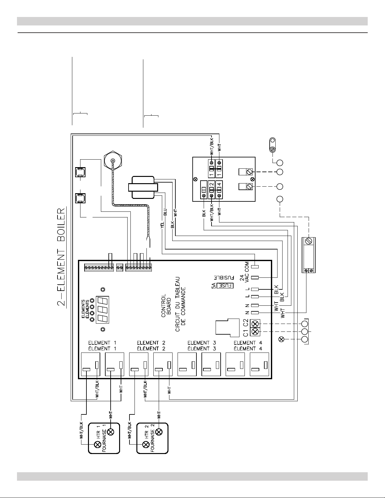
Figure 9 - Wiring Diagram 2 Element w/ Breakers
19
Page 20
R (T)
W (T)CDHW
ODT
ODT
LMC
DHW
DEMAND PUMP
POMPE
LMC
T Aux
T Aux
HL
HL
FLO
LWC
LWC
WT
FLO
WT
RED
RED
RED
NEUTRAL BLOCK
N
MISE À LA TERRE DE L'APPAREIL
FIELD SUPPLIED POWER
PER NEC, CEC AND LOCAL CODES
EQUIPMENT GROUND
L1 L2
GN
BLK
WHT
WT SENSOR
RED
RED
RED
HIGH LIMITS
LOAD CENTER
PANNEAU DE DISTRIBUTION
NEC CLASS 2
LOW VOLT
CONNECTIONS
Low Volt Connections
R (T)
W (T)
C
Domestic Hot Water Thermostat
DHW
Not UsedODT
Load Management ControlLMC
Auxillary Appliance
T Aux
High LimitHLFlow AlarmFLO
Low Water AlarmLCO
Water Temperature SensorWT
Comfort Heating Thermostat
Thermostat de chauffage
tout confort
Raccordements de basse tension
R (T)
W (T)
C
Thermostat à eau chaude
DHW
InutiliséODT
Commande de gestion de chargeLMC
Appareil auxiliaire
T Aux
Limite supérieure
HL
Alarme de débitFLO
Alarme de manque d'eau
LCO
Capteur de la température de l'eau WT
domestique
RACCORDEMENTS EFFECTUÉS SUR
PLACE CONFORMÉMENT AU NEC/CCE
ET AUX CODES LOCAUX EN VIGUEUR
PLAQUE NEUTRE
DEMANDE
BLU - BLEU
BLK - NOIR
CODE DE COULEURS
RD - ROUGE
YEL - JAUNE
WHT - BLANC
PUMP
POMPE
NEC CATÉGORIE 2
BASSE TENSION
RACCORDEMENTS
CAPTEUR WT
LIMITES SUPÉRIEURES
TRANSFORMER
TRANSFORMATEUR
G
L1G N
WIRING DIAGRAMS
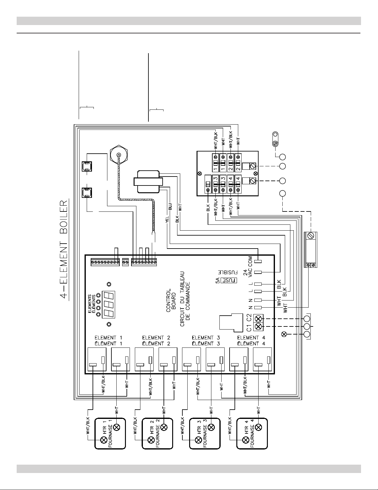
Figure 10 - Wiring Diagram 4 Element w/ Breakers
20
Page 21
STARTUP AND SEASONAL MAINTENANCE
Use qualied service agency for annual inspection of
boiler and heating system.
NOTICE
Label all wires prior to disconnection when servicing
controls. Wiring errors can cause improper and
dangerous operation. Verify proper operation after
service.
Placing Hydronic block into service.
1.
Verify hydronic block circuit breaker or switch at service
entrance and hydronic block circuit breakers within unit
are in "Off" position.
NOTICE
Only propylene glycol can be used in heating system
to prevent freezing. Recommendation is maximum
40% or less propylene glycol mixture to ensure
proper operation of electric boiler.
2.
Fill heating system with water until pressure is 10-15
PSIG. Check for leaks, repair if necessary, purge all air
from system.
8.
When thermostat calls for heat, circulator will be
energized and green pump LED will light. Heating
elements are energized with green heating element
LEDs. Once boiler water temperature reaches set point
temperature controller will regulate water temperature
by staging its elements. Number of elements which
stay on is based on heating demand and set point of
boiler water temperature. After all room thermostats
are satised, controller de-energizes elements one after
another, and switches pump off after 3 minutes.
NOTICE
Failure to vent and keep air out of heating system
will result in damage to heating elements in hydronic
block. Damage due to element dry re is not covered
by manufacturer's warranty.
3.
Set boiler operating temperature to desired heating
water temperature. See Sequence of Operation.
Boiler is equipped with a secondary high-limit
temperature device set at 200° F as safety limit
control. High limit temperature device has automatic
reset function and will reset at 170° F.
4.
Turn on hydronic block circuit breaker at service
entrance and/or disconnect switch and all circuit
breakers on hydronic block.
5.
Set room, thermostat above room temperature.
Circulator pump will now operate.
6.
Check system again for leaks. Allow circulator pump to
run until all air has been vented from system. Gurgling
or rushing sound indicates presence of air. Do no allow
electric elements to re until all air is purged from
system. Reset room thermostat if needed. Re-purge
boiler if necessary.
7.
Hydronic block will start to produce heat. Listen for
air passing through system as water temperature
increases. Water pressure will rise somewhat as
temperature increases - this is normal as long as the
pressure remains less than 25 PSIG.
21
Page 22

GENERAL MAINTENANCE
Hydronic block requires minimum periodic maintenance.
Annual maintenance allow for trouble free operation.
WARNING
Electrical shock hazard. Turn OFF electrical power
supply at main power switch before servicing unit.
Service shall be preformed by a qualied service
agent. Failure to do so could result in death or
serious injury.
1.
Boiler is designed to provide years of trouble free
performance under normal operating conditions.
Conduct general external examination at beginning of
each heating season and at mid-heating seating season
to assure good working performance continues. A
qualied service technician should examine at least once
every year.
2.
Do not store anything against boiler or allow dirt or
debris to accumulate in area immediately surrounding
boiler.
3.
Elements will burn out if boiler is not adequately lled
with water when electrical power is turned on. Do
not connect thermostat wire until system has been
lled with water. Drain water out of system only when
absolutely necessary to make repairs or prevent freezeup during extended cold weather shutdown.
4.
Check temperature and pressure gauge frequently.
During normal operating conditions, pressure should
be stable throughout heating season. If pressure under
normal operating conditions consistently rises and falls
over period of time, this can indicate ll valve leak,
system leak, or compression tank malfunction. Leaks
anywhere must be repaired immediately. If leaks or
signicant pressure uctuations are observed, call for
service immediately.
5.
Test safety relief valve for proper operation. Refer to
valve manufacturer's instructions packaged with relief
valve.
6.
Check eld entrance wire connections to unit for any
signs of looseness or over heating. Verify wire lugs
are tight and torqued to manufacture recommended
settings - see Table B
7.
Check all heating element wiring for signs of dark or
damaged connections. Replace if any sign of failure
exists.
22
Page 23
ADDITIONAL WIRING DIAGRAMS
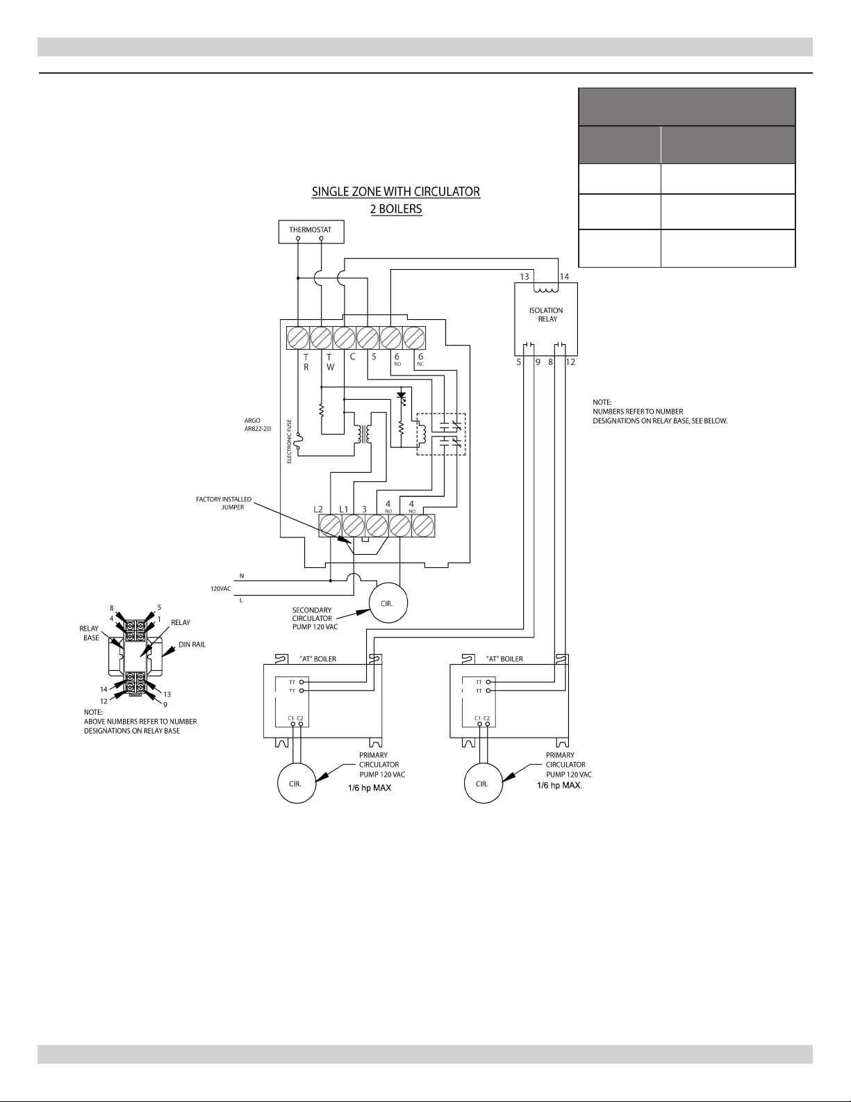
Figure 11 - Single Zone with Circulator - 2 Boilers
ISOLATION RELAY
ITEM
NUMBER
DESCRIPTION
R35C Relay 10A 24VAC
240004745
240004746
Relay Base, DIN Rail
Mount
DIN Rail Approx. 2"
Long
R(T)
W(T)
R(T)
W(T)
(1/16 Hsp. Max.) (1/16 Hsp. Max.)
23
Page 24
ADDITIONAL WIRING DIAGRAMS
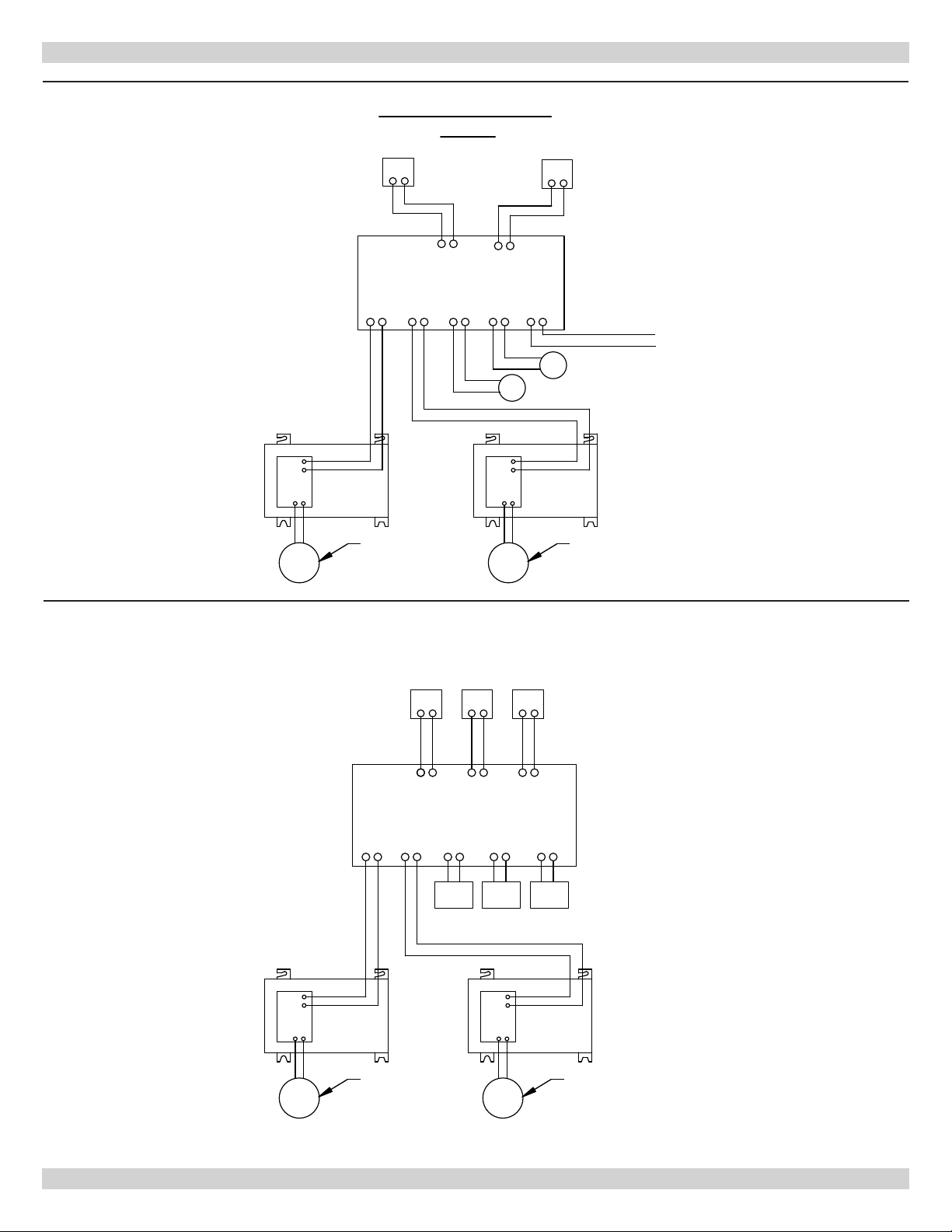
Figure 12 - Two Zones with Circulator - 2 Boilers
TWO ZONES WITH CIRCULATORS
2 BOILERS
ZONE 1
TR TW
ZONE 1
THERMOSTATS
ZONE 1 ZONE 2
X2 X2 L N L N L N
R(T)
W(T)
TT
TT
C1 C2
CIR.
ARGO
ARM-2P
"AT" BOILER
ISOLATED
SWITCH
X1 X1
PRIMARY
CIRCULATOR
PUMP 120 VAC
TR TW
ZONE 2
R(T)
TT
W(T)
TT
C1 C2
CIR.
CIR.
"AT" BOILER
ZONE 2
120
VAC
CIR.
CIRCULATOR PUMPS
(120 VAC)
PRIMARY
CIRCULATOR
PUMP 120 VAC
(1/6 hp MAX)(1/6 hp MAX)
THERMOSTAT
SPST (2 WIRE)
24 VAC
NOTE:
IF CONTROL ONLY CONTAINS ONE ISOLATED
END SWITCH, PLEASE CONTACT TECHNICAL
SERVICE FOR PROPER INSTALLATION.
120 VAC
Figure 13 - Three Zones with Zone Control Valves - 2 Boilers
THREE ZONES WITH ZONE CONTROL VALVES
2 BOILERS
R(T)
W(T)
C1 C2
TT
TT
ARGO
AZ-3
"AT" BOILER
X1 X1
END
SWITCH
ZONE 1
X2 X2
T T
THERMOSTATS
ZONE 1 ZONE 2
ZONE
VALVE
ZONE 2 ZONE 1
ZONE 2
T T
ZONE
VALVE
R(T)
W(T)
C1 C2
"AT" BOILER
TT
TT
ZONE 3
T T
ZONE 3
ZONE 3
ZONE
VALVE
THERMOSTAT
SPST (2 WIRE)
24 VAC
CIR.
PRIMARY
CIRCULATOR
PUMP 120 VAC
24
CIR.
(1/6 hp MAX)(1/6 hp MAX)
PRIMARY
CIRCULATOR
PUMP 120 VAC
Page 25
"AT" BOILER
C1
C2
CIR.
CIRCULATOR
PUMP 120 VAC
TT
TT
PRIMARY
X X
ZONE 1 ZONE 2
T T
SWITCH
END
ZONE 1
THERMOSTAT
SPST (2 WIRE)
ARGO
AZ-3
ZONE 2
ZONE 1
ZONE 3
T T
ZONE 2
T T
ZONE 3
ZONE 3
ZONE
VALVE
ZONE
VALVE
ZONE
VALVE
THERMOSTATS
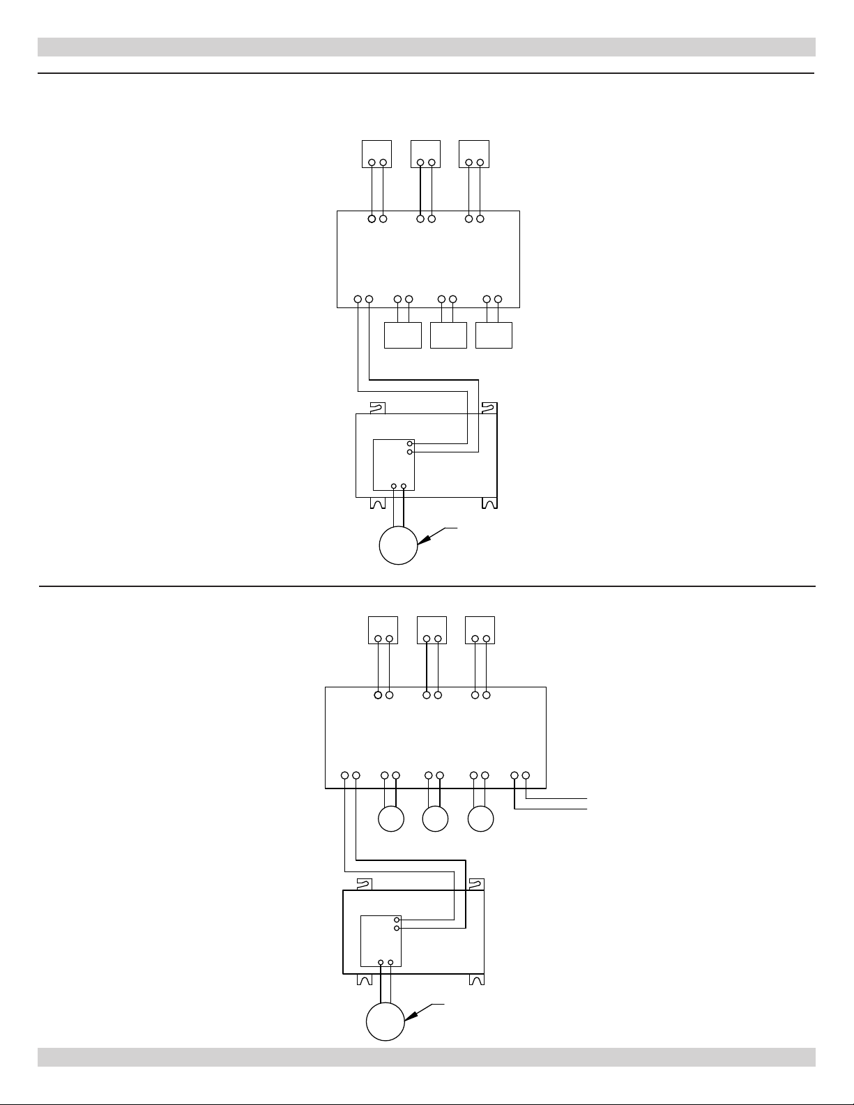
THREE ZONES WITH CONTROL VALVES
"AT" BOILER
C1
C2
CIR.
CIRCULATOR
PUMP 120 VAC
TT
TT
PRIMARY
X X
ZONE 1 ZONE 2
TR T W
SWITCH
ISOLATED
THERMOSTAT
SPST (2 WIRE)
ARGO
ARM-3P
ZONE 2
ZONE 1
ZONE 3
ZONE 3
TR T W TR T W
THERMOSTATS
L N L N L N
120 VAC
L N
CIR. CIR. CIR.
CIRCULATOR PUMPS
(120 VAC)
120 VAC
THREE ZONES WITH CIRCULATORS
ADDITIONAL WIRING DIAGRAMS
Figure 14 - Three Zones Control Valves
Figure 15 - Three Zones with Circulators
R(T)
W(T)
(1/6 hp MAX)
R(T)
W(T)
(1/6 hp MAX)
25
Page 26
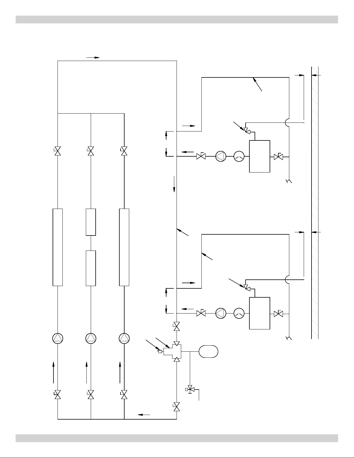
MODULAR BOILER PIPING
FLOW
LOOP
HEATING ZONE 3
HEATING ZONE 2
SECONDARY
PRESSURE
PUMP
RELIEF VALVE
PRESSURE/TEMPERATURE
GAUGE
ARGO
ELECTRIC
BOILER
VALVE
DRAIN
FLOW
SUPPLY HEADER
PRIMARY
LOOP
FLOW
VALVE
BOILER
12"
MAX
VALVE
VALVE
FLOW
HEATING ZONE 1
PIPE TO WITHIN 6" OF FLOOR
FLOOR
PIPE TO WITHIN 6" OF FLOOR
MODULAR BOILER PIPING
PUMP
CIRCULATOR
FLOW
PUMP
CIRCULATOR
FLOW
VALVE VALVE
LOOP
PUMP
BOILER
PRESSURE
RELIEF VALVE
PRESSURE/TEMPERATURE
GAUGE
ARGO
ELECTRIC
BOILER
VALVE
DRAIN
FLOW
SECONDARY
12"
MAX
VALVE
AIR SEPERATOR
PUMP
CIRCULATOR
FLOW
VALVE
AUTOMATIC AIR VENT
VALVE
FLOW
FLOW
VALVE
VALVE
TANK
EXPANSION
FILL
VALVE
26
Page 27
TROUBLESHOOTING
This section is to assist service technician when trouble
shooting electric boiler. It is important to isolate before
proceeding. Control error codes can be helpful identifying
cause of problem. If you suspect wiring fault, check all
external wiring and wiring connections following wiring
diagram label on inside of boiler's cover. Additional wiring
diagram is included with this manual.
WARNING
Electrical shock hazard. Turn OFF electrical power
supply at service panel before making electrical
connections. Failure to do so could result in death
or serious injury.
Noisy Boiler
• Check water pressure of boiler. Should be 15-25 PSIG.
• Check for air within system. Install proper air vents and
purge unit as necessary.
Heating Element Change
Heating element change, use following procedure:
7.
After element has been removed, carefully clean any
remaining gasket material from casting surface. Take
care not to scratch or score surface.
8.
Install new gasket and heating element while assuring
element is correctly positioned.
9.
Close relief valve. Open feed line valve and check for
leaks. Open gate valves. Install heating element wires
and cabinet cover.
10.
Refer to "Startup and Seasonal Maintenance" for
purging of air prior to energizing heating elements.
1.
Turn off hydronic unit circuit breaker at service
entrance and/or disconnect switch.
2.
Close gate valves near inlet and outlet of hydronic
block.
3.
Close feed line valve if using automatic ll.
4.
Open drain valve and allow water to drain from boiler.
Manual operation of relief valve will assist drainage by
allowing air to enter.
5.
Remove cabinet cover and disconnect two wires
attached to effected heating element.
6.
Remove four bolts securing heating element to casting
pry element loose. Take note of markings on element
ange to assure proper reinstallation.
27
Page 28
TROUBLESHOOTING
WARNING
Electrical shock hazard. Turn OFF electrical power
supply at main power switch before servicing unit.
Service shall be preformed by a qualied service
agent. Failure to do so could result in death or
serious injury.
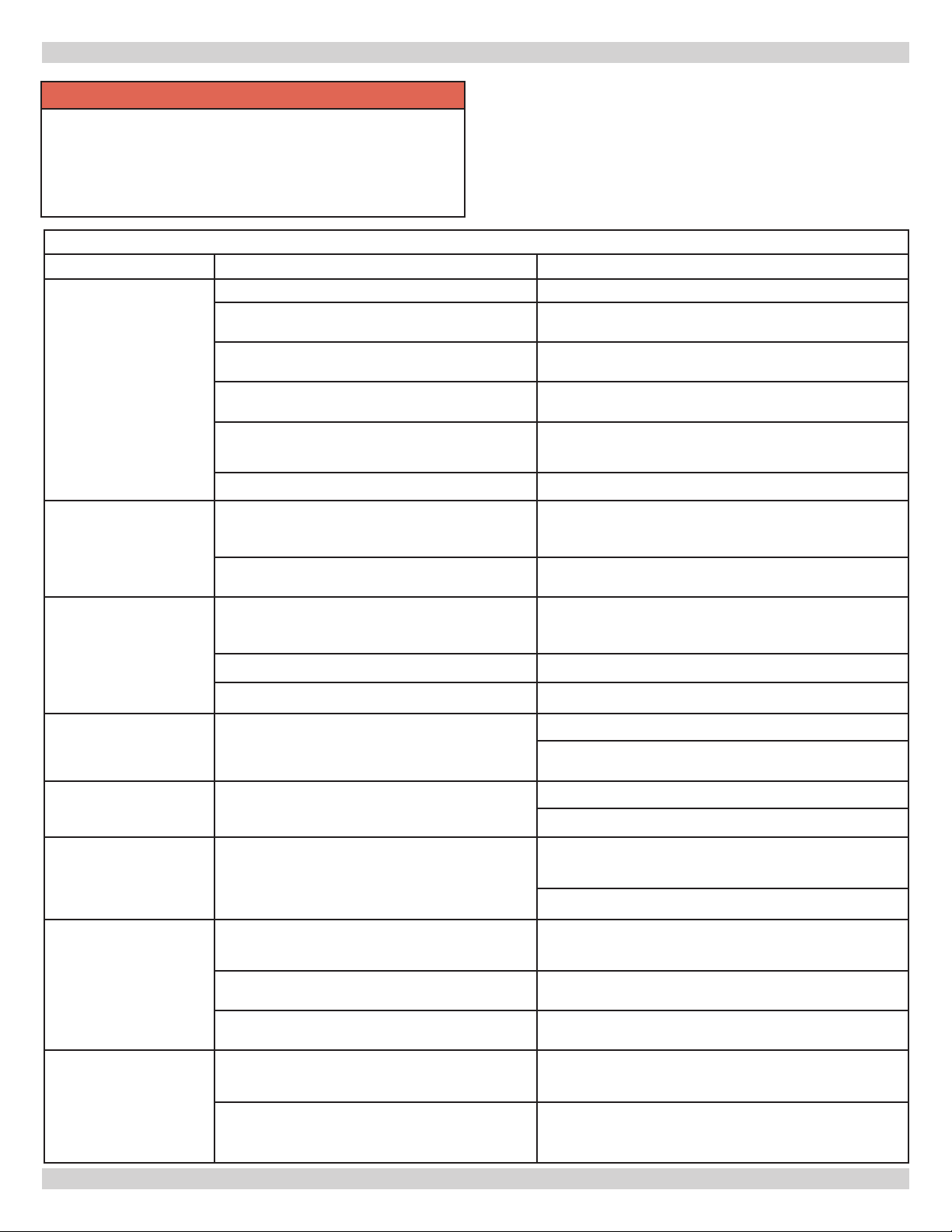
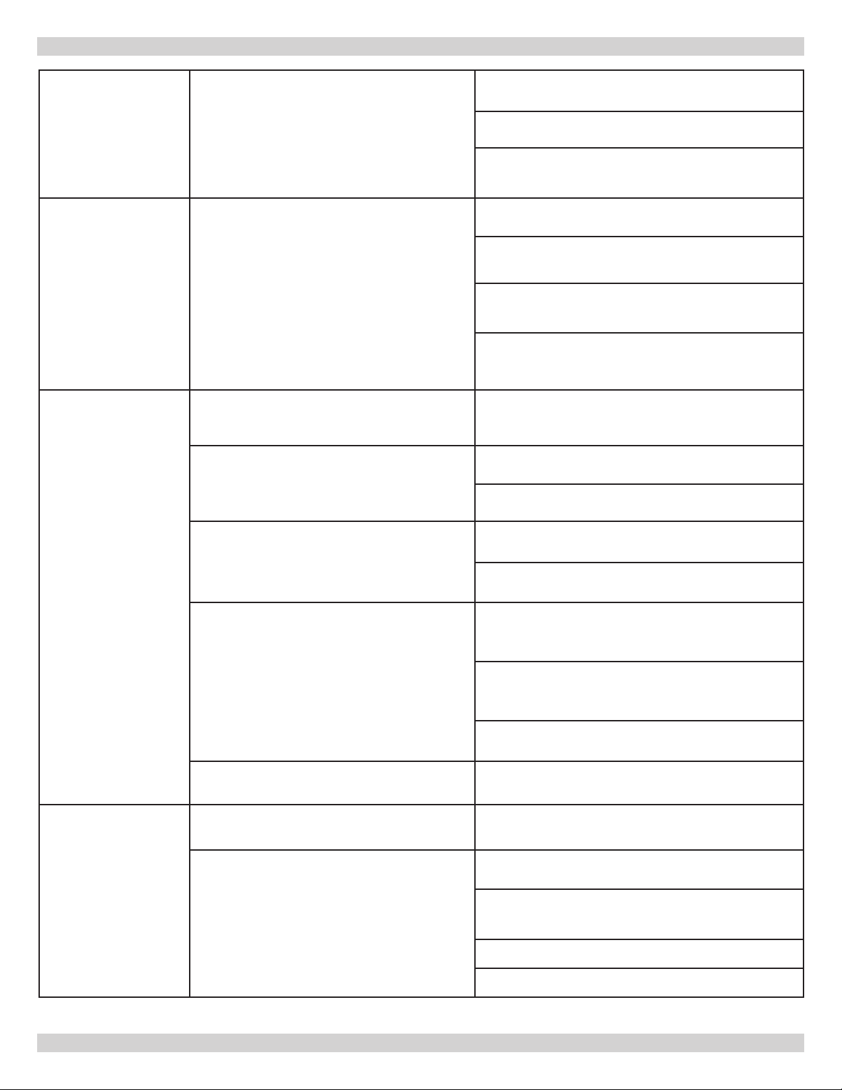
AT Boiler Trouble Shooting
Fault Possible Cause Corrective action
Is circulator pump functional? If pump is not working replace.
Check temperature rise across boiler.
Check for temperature overshoot after
completion of heating cycle.
HL - High Limit Trip
Check that HL screw terminals on control board
are tight.
If > 20°F - Increase ow rate by using larger pump or
pipe size.
If greater than 10°F then increase differential setting.
Are high limit switches open while water
temperatures less than 200°F (<200°F)?
Is heat load too small? Check heat load calculations.
AbP - Abnormal Power
Alarm
Water temperature
overshoots set point
temperature.
DFF - Dry Failure Alarm Air in boiler?
tSO, tSS -
Temperature sensor
failure.
CHF
Control Hardware Failure
Power too high or too low?
Power is OK while unit is off but drops when unit
is on.
A small overshoot is normal, however if
overshoot is greater than 10°F (OS > 10°F)
then check the following.
Boiler is oversized for heating zone? Check heat load calculations.
Differential is too low? Increase differential temperature setting.
Check resistance value of sensor using R/T
chart.
Check for all wiring for damage or loose
connections.
Check high limit switches with Ohm meter. Replace high
limit(s) open.
Check Incoming power is between 197Vac and 240Vac
(197< IP <240Vac). If power outside range, contact
electrician to have power corrected.
Check for adequate wiring and breaker size.
Check temperature rise across boiler is less than 20°F.
If too high then increase ow rate through boiler, use
larger boiler pump if necessary.
Purge boiler until all air is removed.
Check that adequate air vents located in critical system
high points. Add vents as necessary.
Good - Check for loose WT terminals on control board.
Bad - Replace Sensor.
Bad - Tighten any loose terminals. Replace Damaged
Wiring.
Good - Replace Control.
Circuit Beakers Trip
r1, r2, r3, r4
Relay failure code
Inspect wiring for damage or short circuits.
Inspect heating elements, Check element
resistance value is between 9-20Ω (Ohms).
Is current draw between 12 and 25A (Amps) per
element?
Is heating element wiring loose or damaged?
Is heat relay stuck closed?
28
Bad-Tighten any loose terminals. Replace damaged
wiring.
Bad - Replace heating element(s).
Bad - Replace heating element(s).
Bad-Tighten any loose terminals. Replace Damaged
Wiring.
With power removed check relay contacts with an Ohm
meter. Replace control if relay is stuck closed.
Page 29
TROUBLESHOOTING
N - Check control board jumper is in place and secure.
Tighten FLO screws if needed.
FLO
Flow Switch Alarm
LWC
Low Water Cutoff Alarm
Is ow switch installed?
Is LWCO Installed?
Is electrical power applied to unit?
Field Service circuit breakers tripped?
Y - System air locked - Purge system and add venting
as needed.
Y - Check that ow switch is functioning properly.
Conduct self test on ow switch (Consult manufactures
instructions).
N - Check control board jumper is in place and secure.
Tighten LWC screws if needed.
Y - System air locked - Purge system, add venting as
needed.
Y - System low on water - Check water feed to boiler,
check for leaks. Repair as needed.
Y - check that LWCO is functioning properly. Conduct
self test on LWCO switch (Consult manufactures
instructions).
Check Incoming power is between 197Vac and 240Vac
(197< IP <240Vac). If power outside range, contact
electrician to have power corrected.
Check for loose or damaged wiring. Replace wiring if
damaged.
Check heating element resistance within 9-20Ω (Ohms).
Replace element if outside range.
Control Display Dark/
Un-responsive
Control functions
correctly however does
not heat water.
AT boiler 15A breaker tripped?
Is control transformer functioning?
Is wiring loose or damaged?
Heating element(s) failed?
AT boiler 40A breakers tripped?
Inspect control and all wiring for damage. Replace any
damaged components or wiring.
Inspect eld installed thermostat and wiring for
damage. Repair and replace as necessary.
Check for 24Vac on R and C terminals of control board.
If less than 18Vac on R & C with primary side between
104 and 130Vac then replace transformer.
With power removed check control transformer primary
and secondary windings for open or short. If windings
are open or short, replace transformer.
With power removed check 5A fuse on control board. If
bad replace fuse.
Inspect all thermostat wiring for damage loose
connections or damage. Replace wiring if necessary.
Check heating element resistance within 9-20Ω (Ohms).
Replace element if outside range.
Check for loose or damaged wiring. Replace wiring if
damaged.
Check heating element resistance within 9-20Ω (Ohms).
Replace element if outside range.
29
Check control board for damaged heat relay(s).
Check boiler pump is operational. Replace if necessary.
Page 30
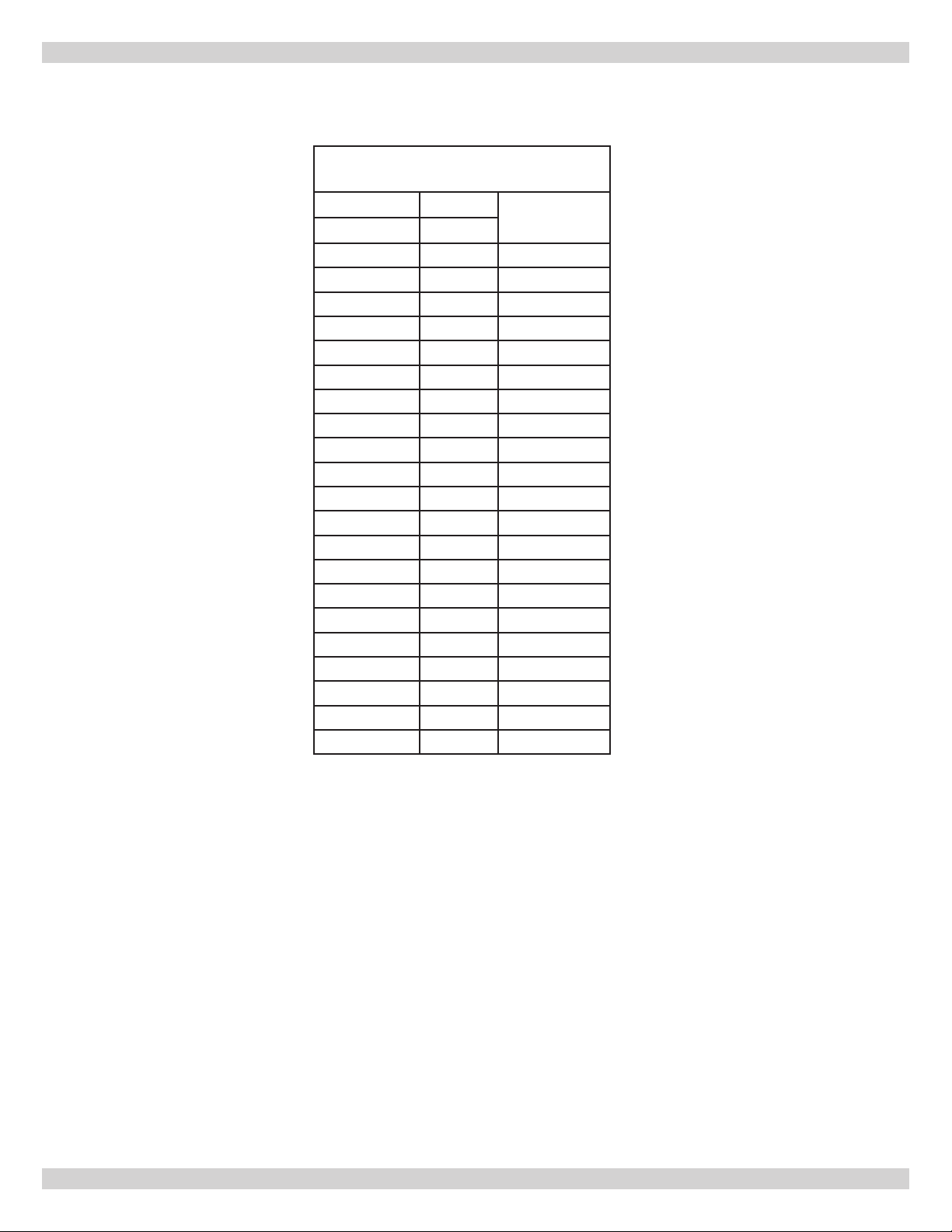
RESISTANCE VS. TEMPERATURE TABLE
Resistance Vs. Temperature
Table
Temp Temp
Ohms (Ω)
(°C) (°F)
0 32.0 32,650
5 41.0 25,392
10 50.0 19,901
15 59.0 15,712
20 68.0 12,493
25 77.0 10,000
30 86.0 8,057
35 95.0 6,531
40 104.0 5,326
45 113.0 4,368
50 122.0 3,602
55 131.0 2,986
60 140.0 2,488
65 149.0 2,083
70 158.0 1,752
75 167.0 1,480
80 176.0 1,255
85 185.0 1,070
90 194.0 916
95 203.0 787
100 212.0 679
30
Page 31

This Page Intentionally Left Blank
31
Page 32
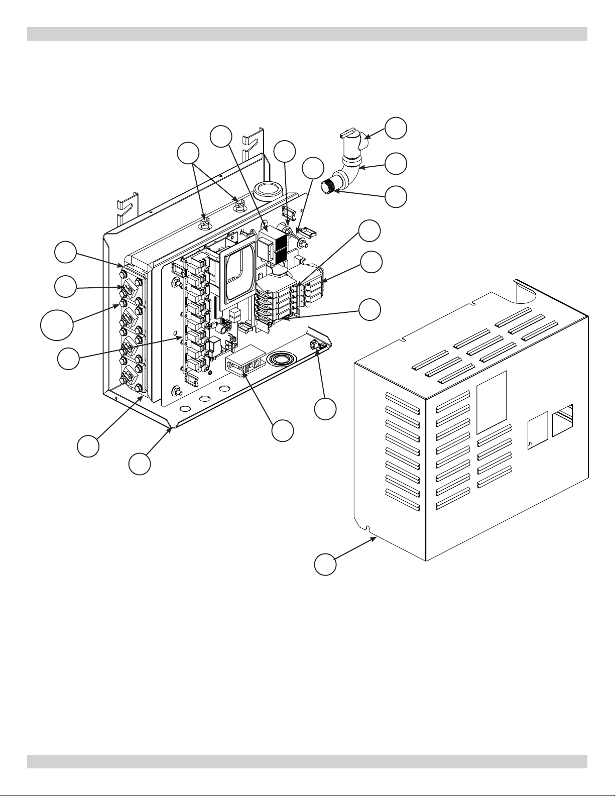
PARTS LIST - 2 & 4 ELEMENT BOILER
14
13
13a
13B
12
15
16
17
18
1
2
3
4
5
6
8
11
9
10
7
32
Page 33
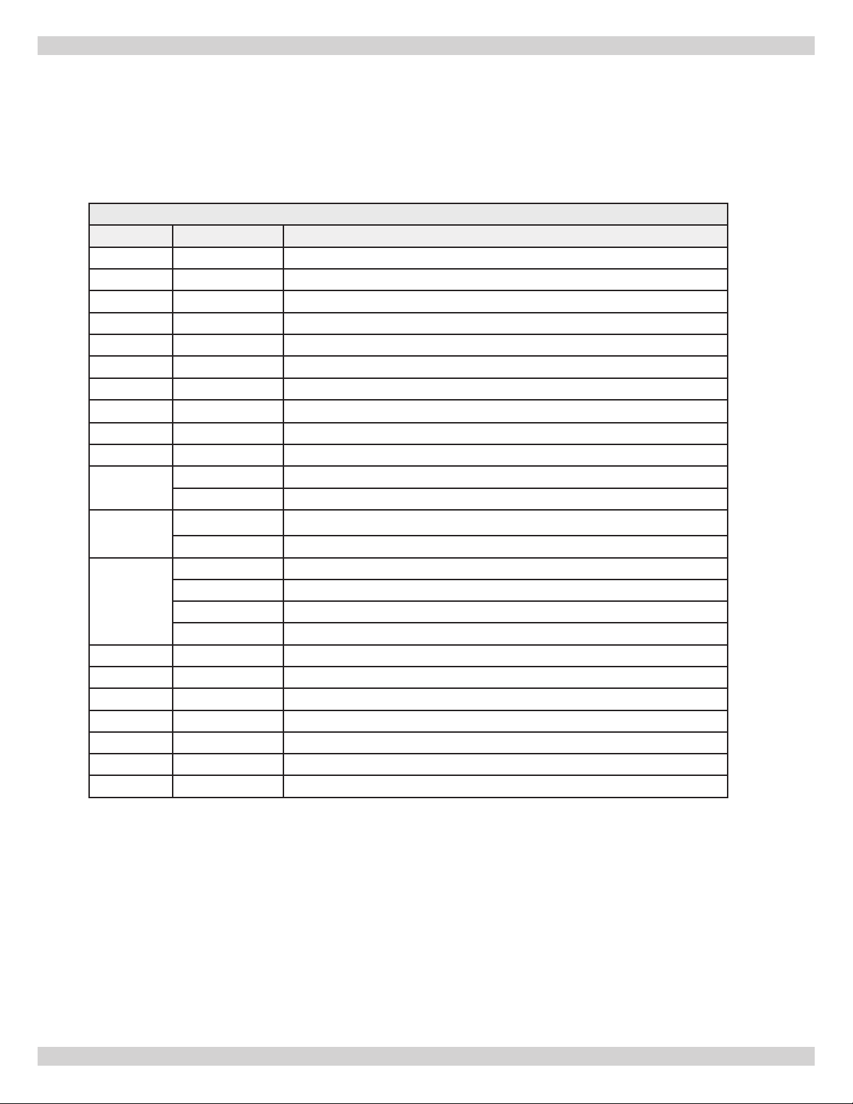
PARTS LIST - 2 & 4 ELEMENT BOILER
2 & 4 Element Electric Boiler
Item Part Number Description
1 V1 Relief Valve - 30 PSI
2 E1 Elbow 3/4" x 90°
3 N1 Nipple 3/4" x 2"
4 B28 Circuit Breaker 15 A - 1 Pole - G.E. THQP 115
5 B27 Circuit Breaker 40 A - 2 Pole - G.E. THQP 240
6 I25 Load Center Assemly - G. E. TLM812U2
7 109008918 Cabinet
8
9 B194 Nuetral Terminal Block
10 P23 Chassis, Back/Bottom
11
12
13
13a S66 Bolt, 5/16 - 18 x 3/4
13b W29 Washer, Flat 5/16"
14 G12 Gasket, Heating Element
15 S47 Safety Limit Control (High Limit, Fixed Temperature)
16 119000002 Transformer 115/24V, 40VA
17 240010289 Water Temperature Sensor Kit
18 240004756 Brass Well
L9 Ground Lug
C57 Pressure Vessel - Cast Iron, 2 Element
C32 Pressure Vessel - Cast Iron, 4 Element
240010295 Control Board - 2 Element, kit, includes wires
240010296 Control Board - 4 Element, kit, includes wires
E13 Heating Element - 3KW/240 Volt
E14 Heating Element - 4KW/240 Volt
E15 Heating Element - 5KW/240 Volt
E16 Heating Element - 6KW/240 Volt
33
Page 34
NOTES
34
Page 35
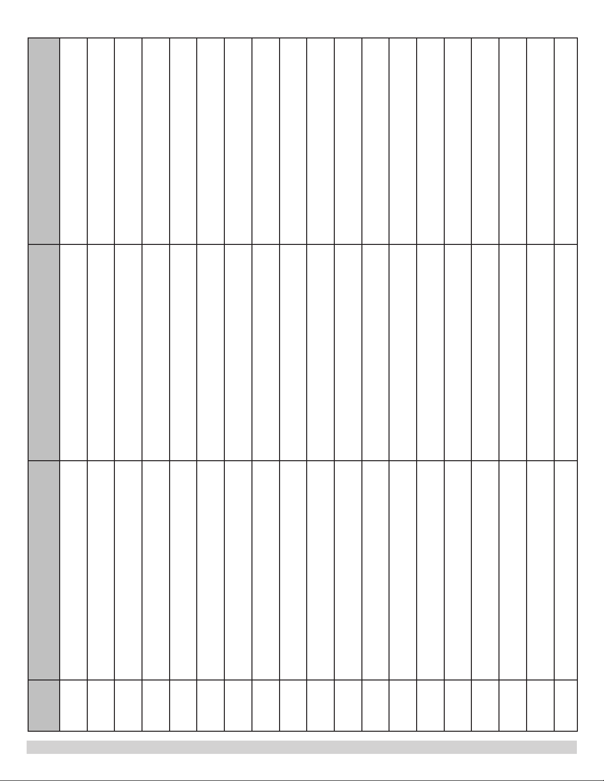
Company Address & Phone #Company Name & Tech InitialsService PerformedDate
35
Page 36
HOMEOWNER'S REFERENCE TABLE
Model Number: _____________________________________________
Serial Number: ______________________________________________
Date Installed: ______________________________________________
Contractor: _________________________________________________
Contact: ___________________________________________________
Address: ___________________________________________________
___________________________________________________________
Telephone Number: __________________________________________
After Hours Number: _________________________________________
If different from Installation Contractor:
Service Tech: _______________________________________________
Telephone Number: __________________________________________
After Hours Number: _________________________________________
ECR International Inc.
2201 Dwyer Avenue
Utica, NY 13501
www.ecrinternational.com
www.argocontrols.com
 Loading...