

Argo AER 536 SC3E, AER 525 SC3E, AER 525 SCL3E, AS 436 C, AER 536 SCL3E Technical Data & Service Manual
...Page 1
1
Section
2
3
4
5
TECHNICAL DATA
&
SERVICE MANUAL
AS 425 C / AER 525 SCE
AS 425 C / AER 525 SC3E
AS 425 C / AER 525 SCL3E
AS 436 C / AER 536 SC3E
AS 436 C / AER 536 SCL3E
AS 448 C / AER 548 SC3E
AS 448 C / AER 548 SCL3E
AD 425 CW / AER 525 SCE
AD 425 CW / AER 525 SC3E
AD 425 CW / AER 525 SCL3E
AD 436 CW / AER 536 SC3E
AD 436 CW / AER 536 SCL3E
AD 448 CW / AER 548 SC3E
AD 448 CW / AER 548 SCL3E
AC 425 C / AER 525 SCE
AC 425 C / AER 525 SC3E
AC 425 C / AER 525 SCL3E
AC 436 C / AER 536 SC3E
AC 436 C / AER 536 SCL3E
AC 448 C / AER 548 SC3E
AC 448 C / AER 548 SCL3E
SPLIT SYSTEM AIR CONDITIONER
Indoor Unit Outdoor Unit
AER 525 SCE - AER 525 SC3E
AER 525 SCL3E
AER 536 SC3E - AER 548 SC3E
AER 536 SCL3E - AER 548 SCL3E
AS 425 C
AD 425 CW
AC 425 C
AC 436 C
AC 448 C
AS 436 C
AS 448 C
AD 436 CW
AD 448 CW
0.8180.229.0 07/02
®
Page 2
i
Please Read Before Starting
This air conditioning system meets strict safety and
operating standards. As the installer or service person, it
is an important part of your job to install or service the
system so it operates safely and efficiently.
For safe installation and trouble-free operation, you
must :
Carefully read this instruction booklet before beginning.
Follow each installation or repair step exactly as shown.
Observe all local, state, and national electrical codes.
Pay close attention to all warning and caution notices
given in this manual.
This symbol refers to a
hazard or unsafe practice
which can result in severe
personal injury or death.
This symbol refers to a
hazard or unsafe practice
which can result in personal
injury or product or property
damage.
If Necessary, Get Help
These instructions are all you need for most installation
sites and maintenance conditions. If you require help for a
special problem, contact our sales/service outlet or your
certified dealer for additional instructions.
In Case of Improper Installation
The manufacturer shall in no way be responsible for
improper installation or maintenance service, including
failure to follow the instructions in this document.
SPECIAL PRECAUTIONS
When Wiring
……………………………………………………………………
ELECTRICAL SHOCK CAN CAUSE
SEVERE PERSONAL INJURY OR DEATH.
ONLY A QUALIFIED, EXPERIENCED
ELECTRICIAN SHOULD ATTEMPT TO
WIRE THIS SYSTEM.
• Do not supply power to the unit until all wiring and
tubing are completed or reconnected and checked.
• Highly dangerous electrical voltages are used in this
system. Carefully refer to the wiring diagram and these
instructions when wiring. Improper connections and
inadequate grounding can cause accidental injury or
death.
• Ground the unit following local electrical codes.
• Connect all wiring tightly. Loose wiring may cause
overheating at connection points and a possible fire
hazard.
When Transporting
……………………………………………………………………
Be careful when picking up and moving the indoor and
outdoor units. Get a partner to help, and bend your knees
when lifting to reduce strain on your back. Sharp edges or
thin aluminum fins on the air conditioner can cut your
fingers.
Important
CAUTION
When Installing
……………………………………………………………………
…In a Room
Properly insulate any tubing run inside a room to prevent
“sweating” that can cause dripping and water damage to
walls and floors.
…In Moist or Uneven Locations
Use a raised concrete pad or concrete blocks to provide a
solid, level foundation for the outdoor unit. This prevents
water damage and abnormal vibration.
…In an area with High Winds
Securely anchor the outdoor unit down with bolts and a
metal frame. Provide a suitable air baffle.
…In a Snowy Area (for Heat Pump-type Systems)
Install the outdoor unit on a raised platform that is higher
than drifting snow. Provide snow vents.
When Connecting Refrigerant Tubing
……………………………………………………………………
• Ventilate the room well, in the event that refrigerant gas
leaks during the installation. Be careful not to allow
contact of the refrigerant gas with a flame as this will
cause the generation of poisonous gas.
• Keep all tubing runs as short as possible.
• Use the flare method for connecting tubing.
• Apply refrigerant lubricant to the matching surfaces of
the flare and union tubes before connecting them, then
tighten the nut with a torque wrench for a leak-free
connection.
• Check carefully for leaks before starting the test run.
NOTE
Depending on the system type, liquid and gas lines may
be either narrow or wide. Therefore, to avoid confusion the
refrigerant tubing for your particular model is specified as
either “narrow” or “wide” rather than as “liquid” or “gas”.
When Servicing
……………………………………………………………………
• Turn the power OFF at the main power box (mains)
before opening the unit to check or repair electrical
parts and wiring.
• Keep your fingers and clothing away from any moving
parts.
• Clean up the site when installation is finished. Check
that no metal scraps or bits of wiring have been left
inside the unit.
CAUTION
• Ventilate any enclosed areas when installing or testing
the refrigeration system. Contact of refrigerant gas with
fire or heat can produce poisonous gas.
• Confirm after installation that no refrigerant gas is
leaking. If the gas comes in contact with a burning
stove, gas water heater, electric room heater or other
heat source, it can cause the generation of poisonous
gas.
Page 3

– I-1 –
1. SPECIFICATIONS
1-1 Unit Specifications ................................................................................. I - 2
4-Way Air Discharge Semi-concealed Type...........................................I - 2
Ceiling Mounted Type..............................................................................I - 9
Concealed Duct Type ..............................................................................I - 16
1-2 Major Component Specifications.............................................................I - 30
(A)Indoor Units........................................................................................I - 30
(B)Outdoor Units .....................................................................................I - 41
1-3 Other Component Specifications.............................................................I - 46
46
47
48
50
4-Way Air Discharge Semi-concealed Type...........................................I -
Ceiling Mounted Type..............................................................................I -
I -
Concealed Duct Type ..............................................................................
Outdoor Units...........................................................................................I -
1-4 Dimensional Data ....................................................................................I - 52
(A)Indoor Units........................................................................................I - 52
4-Way Air Discharge Semi-concealed Type.......................................I - 53
Ceiling Mounted Type ........................................................................I - 54
Concealed Duct Type.........................................................................I - 55
(B)Outdoor Units .....................................................................................I - 59
1-5 Refrigerant Flow Diagram........................................................................I - 61
1-6 Operating Range .....................................................................................I - 63
1-7 Cooling Capacity......................................................................................I - 64
1-8 Noise Criterion Curves.............................................................................I - 82
1-9 Indoor Fan Performance..........................................................................I - 87
1-10 Air throw Distance Chart..........................................................................I - 89
1-11 Installation Instructions ............................................................................I - 91
Tubing Length..........................................................................................I - 91
92
Selecting the Installation Site...................................................................I -
Electrical Wiring .......................................................................................I - 95
Electrical Characteristics .........................................................................I - 97
Page 4

– I-2 –
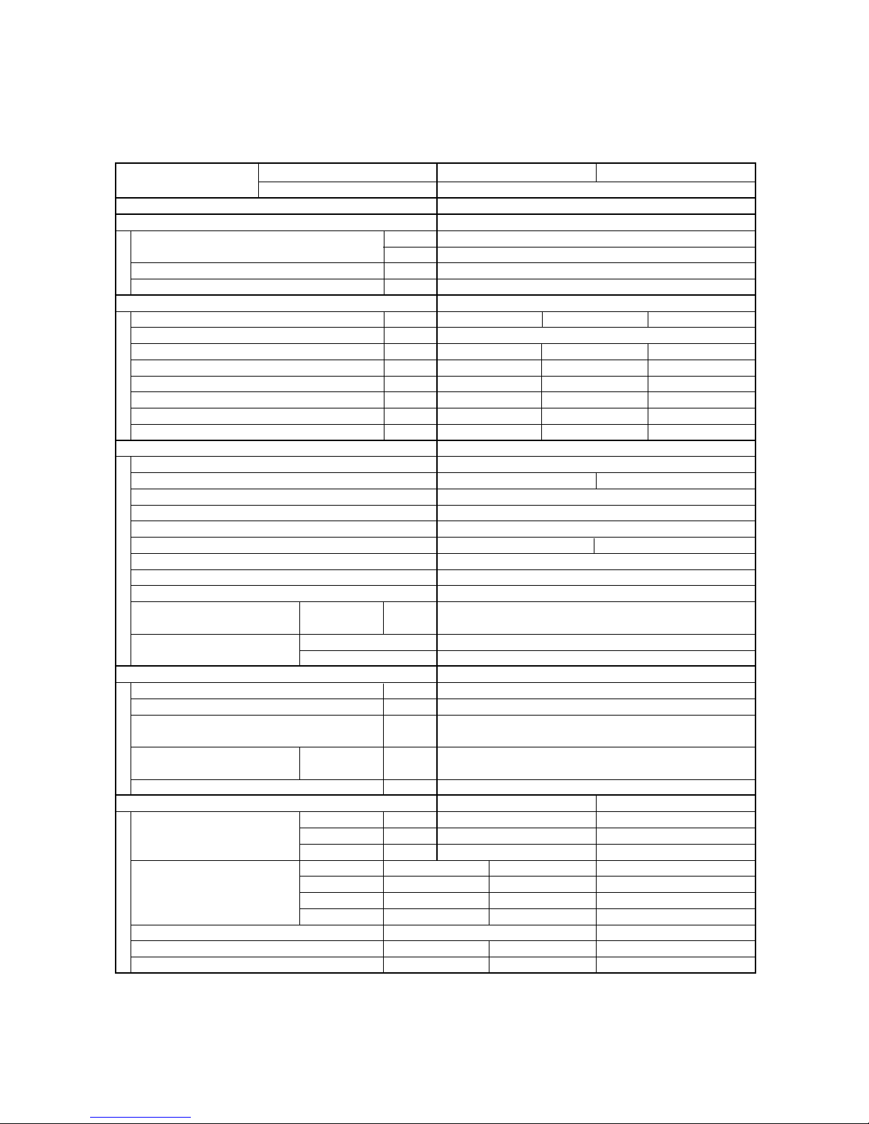
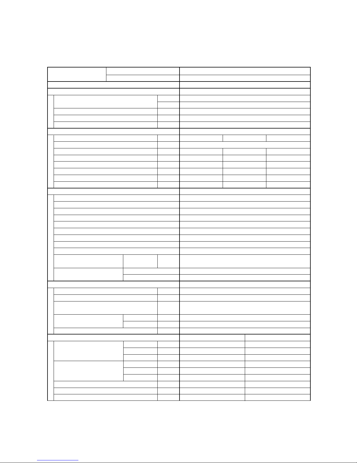
1-1 Unit Specifications
4-Way Air Discharge Semi-concealed Type
MODEL No. Indoor Unit AS425C
Outdoor Unit AER525SCE
POWER SOURCE 220 - 230 - 240 V / 1 phase / 50 Hz
PERFORMANCE Cooling
Capacity kW 7.3
BTU / h 25,000
Air circulation (Hi / Me / Lo) m3/h 1,140 / 1,020 / 840
Moisture removal (High) Liters/h 3.6
ELECTRICAL RATINGS
Voltage rating V 220 230 240
Available voltage range V 198 – 264
Running amperes* A 13.3 13.5 13.6
Max. running amperes** A 14.7 14.7 14.8
Power input kW 2.75 2.87 2.94
Power factor % 94 93 90
C.O.P W / W 2.65 2.54 2.48
Max. starting amperes A 69 72 75
FEATURES
Controls / Thermostat control Microprocessor
Timer ON / OFF 12-hours ON/OFF 24-hours & Program
Fan speeds Indoor / Outdoor 3 and Automatic control / 2 (Auto)
Airflow direction (Indoor) Automatic (Remote control)
Air filter Washable, easy access, long life (2,500 hr)
Remote controller (Option) Wired : RCS-31G(W) Wireless : RCS-5PS3E
Refrigerant control Capillary tube
Drain pump (Drain connection)
Max. head 25 cm above drain connection (25A, OD32 mm)
Compressor Rotary (Sanyo)
Operation sound
Indoor - Hi/Me/Lo
dB - A 37 / 35 / 31
Outdoor - Hi
dB - A 52
Color (Approximate value) Indoor Munsell 10Y9.3 / 0.4, RAL 9010-GL
Outdoor Munsell 6.96Y8.13 / 0.2, RAL 7035-GL
REFRIGERANT TUBING
Limit of tubing length m (ft.) 40 (131 )
Limit of tubing length at shipment m (ft.) 15 ( 49 )
Limit of elevation difference m (ft.) Outdoor unit is higher than indoor unit : 40 (131)
between the two units Outdoor unit is lower than indoor unit : 30 (98)
Refrigerant tube Narrow tube mm (in.) 6.35 (1 / 4)
outer diameter Wide tube mm (in.) 15.88 (5 / 8)
Refrigerant amount at shipment kg R407C - 2.4
DIMENSIONS & WEIGHT Indoor unit (Include panel) Outdoor unit
Unit dimensions Height mm (in.) 328 (12 - 29 / 32) 735 (28 - 30 / 32)
Width mm (in.) 860 (33 - 27 / 32) 940 (37 )
Depth mm (in.) 860 (33 - 27 / 32) 340 (13 - 12 / 32)
Package dimensions Body Panel Outdoor unit
Height mm (in.)
284 (11 - 6 / 32) 104 ( 4 - 3 / 32) 826 (32 - 17 / 32)
Width mm (in.)
824 (32 - 14 / 32) 967 (38 - 2 / 32) 1,016 (40 )
Depth mm (in.)
833 (32 - 25 / 32) 999 (39 -11 / 32) 416 (16 - 12 / 32)
Net weight kg (lb.) 30 (66) 67 ( 148)
Shipping weight kg (lb.) 27 ( 60) 8 ( 18) 73 ( 161)
Shipping volume m
3
(cu. ft) 0.195 ( 6.9) 0.1 ( 3.5) 0.349 (12.3)
DATA SUBJECT TO CHANGE WITHOUT NOTICE.
Cooling:
Rating conditions (*): Indoor air temperature 27 °CDB/19 °C WB, Outdoor air temperature 35 °C DB
Full load conditions (**): Indoor air temperature 32 °CDB/23 °C WB, Outdoor air temperature 43 °C DB
Page 5

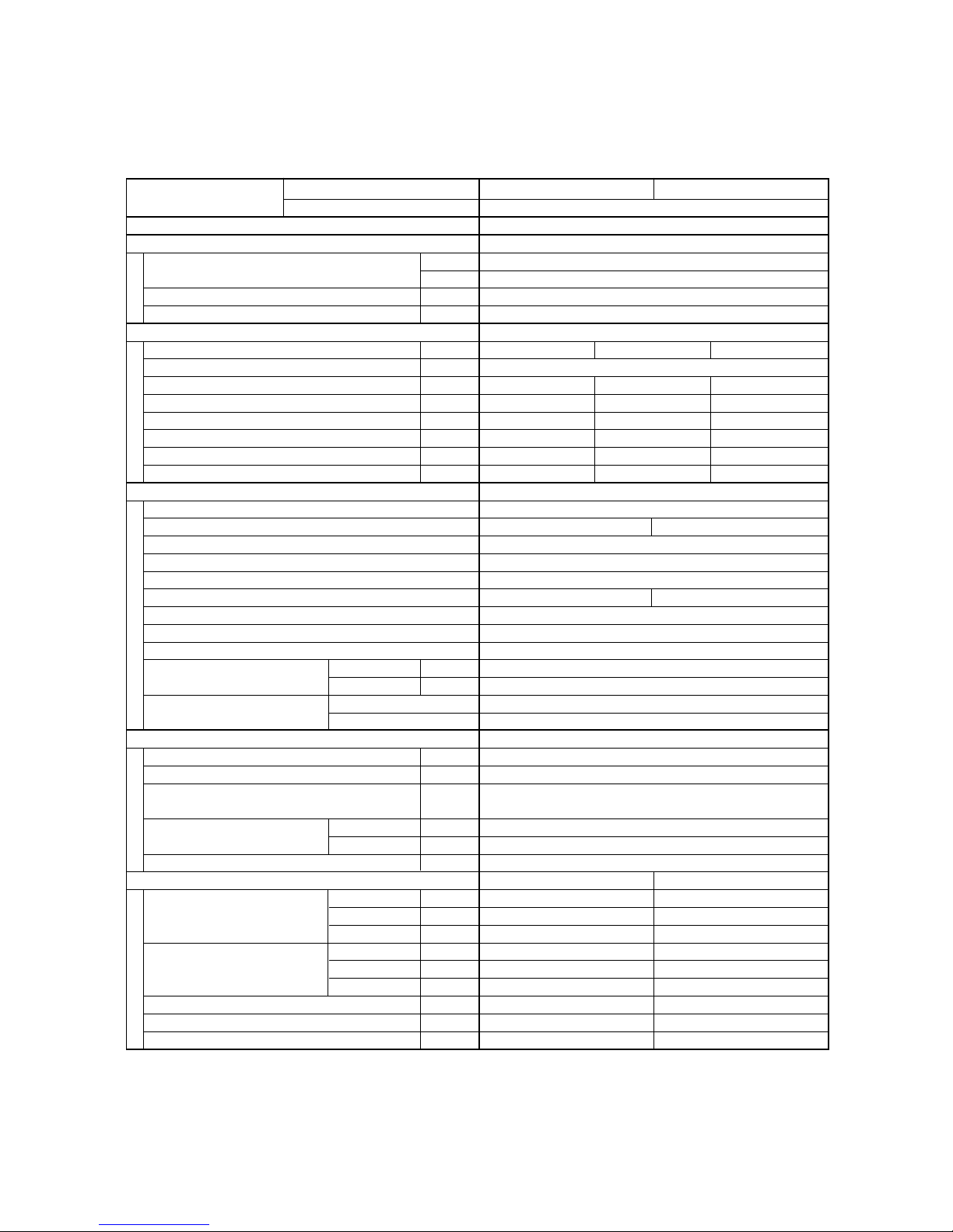
– I-3 –
MODEL No. Indoor Unit AS 425C
Outdoor Unit AER525SC3E
POWER SOURCE 380 - 400 - 415 V / 3N / 50 Hz
PERFORMANCE Cooling
Capacity kW 7.3
BTU / h 25,000
Air circulation (Hi / Me / Lo) m3/h 1,140 / 1,020 / 840
Moisture removal (High) Liters/h 3.6
ELECTRICAL RATINGS
Voltage rating V 380 400 415
Available voltage range V 342 – 456
Running amperes* A 4.82 4.78 4.73
Max. running amperes** A 5.67 5.68 5.69
Power input kW 2.76 2.79 2.82
Power factor % 87 84 83
C.O.P W / W 2.64 2.62 2.59
Max. starting amperes A 27 29 30
FEATURES
Controls / Thermostat control Microprocessor
Timer ON / OFF 12-hours ON/OFF 24-hours & Program
Fan speeds Indoor / Outdoor 3 and Automatic control / 2 (Auto)
Airflow direction (Indoor) Automatic (Remote control)
Air filter Washable, easy access, long life (2,500 hr)
Remote controller (Option) Wired : RCS-31G(W) Wireless : RCS-5PS3E
Refrigerant control Capillary tube
Drain pump (Drain connection)
Max. head 25 cm above drain connection (25A, OD32 mm)
Compressor Rotary (Sanyo)
Operation sound
Indoor - Hi/Me/Lo
dB - A 37 / 35 / 31
Outdoor - Hi
dB - A 52
Color (Approximate value) Indoor Munsell 10Y9.3 / 0.4, RAL 9010-GL
Outdoor Munsell 6.96Y8.13 / 0.2, RAL 7035-GL
REFRIGERANT TUBING
Limit of tubing length m (ft.) 40 (131 )
Limit of tubing length at shipment m (ft.) 15 ( 49 )
Limit of elevation difference m (ft.) Outdoor unit is higher than indoor unit : 40 (131)
between the two units Outdoor unit is lower than indoor unit : 30 (98)
Refrigerant tube Narrow tube mm (in.) 6.35 (1 / 4)
outer diameter Wide tube mm (in.) 15.88 (5 / 8)
Refrigerant amount at shipment kg R407C - 2.4
DIMENSIONS & WEIGHT Indoor unit (Include panel) Outdoor unit
Unit dimensions Height mm (in.) 328 (12 - 29 / 32) 735 (28 - 30 / 32)
Width mm (in.) 860 (33 - 27 / 32) 940 (37 )
Depth mm (in.) 860 (33 - 27 / 32) 340 (13 - 12 / 32)
Package dimensions Body Panel Outdoor unit
Height mm (in.)
284 (11 - 6 / 32) 104 ( 4 - 3 / 32) 826 (32 - 17 / 32)
Width mm (in.)
824 (32 - 14 / 32) 967 (38 - 2 / 32) 1,016 (40 )
Depth mm (in.)
833 (32 - 25 / 32) 999 (39 -11 / 32) 416 (16 - 12 / 32)
Net weight kg (lb.) 30 (66) 67 ( 148)
Shipping weight kg (lb.) 27 ( 60) 8 ( 18) 73 ( 161)
Shipping volume m
3
(cu. ft) 0.195 ( 6.9) 0.1 ( 3.5) 0.349 (12.3)
DATA SUBJECT TO CHANGE WITHOUT NOTICE.
Cooling:
Rating conditions (*): Indoor air temperature 27 °CDB/19 °C WB, Outdoor air temperature 35 °C DB
Full load conditions (**): Indoor air temperature 32 °CDB/23 °C WB, Outdoor air temperature 43 °C DB
Page 6

– I-4 –
MODEL No. Indoor Unit AS425C
Outdoor Unit AER525SCL3E
POWER SOURCE 380 - 400 - 415 V / 3N / 50 Hz
PERFORMANCE Cooling
Capacity kW 7.3
BTU / h 25,000
Air circulation (Hi / Me / Lo) m3/h 1,140 / 1,020 / 840
Moisture removal (High) Liters/h 3.6
ELECTRICAL RATINGS
Voltage rating V 380 400 415
Available voltage range V 342 – 456
Running amperes* A 4.82 4.78 4.73
Max. running amperes** A 5.67 5.68 5.69
Power input kW 2.76 2.79 2.82
Power factor % 87 84 83
C.O.P W / W 2.64 2.62 2.59
Max. starting amperes A 27 29 30
FEATURES
Controls / Thermostat control Microprocessor
Timer ON / OFF 12-hours ON/OFF 24-hours & Program
Fan speeds Indoor / Outdoor 3 and Automatic control / 3 (Auto)
Airflow direction (Indoor) Automatic (Remote control)
Air filter Washable, easy access, long life (2,500 hr)
Remote controller (Option) Wired : RCS-31G(W) Wireless : RCS-5PS3E
Refrigerant control Capillary tube
Drain pump (Drain connection)
Max. head 25 cm above drain connection (25A, OD32 mm)
Compressor Rotary (Sanyo)
Operation sound
Indoor - Hi/Me/Lo
dB - A 37 / 35 / 31
Outdoor - Hi
dB - A 52
Color (Approximate value) Indoor Munsell 10Y9.3 / 0.4, RAL 9010-GL
Outdoor Munsell 6.96Y8.13 / 0.2, RAL 7035-GL
REFRIGERANT TUBING
Limit of tubing length m (ft.) 40 (131 )
Limit of tubing length at shipment m (ft.) 15 ( 49 )
Limit of elevation difference m (ft.) Outdoor unit is higher than indoor unit : 40 (131)
between the two units Outdoor unit is lower than indoor unit : 30 (98)
Refrigerant tube Narrow tube mm (in.) 6.35 (1 / 4)
outer diameter Wide tube mm (in.) 15.88 (5 / 8)
Refrigerant amount at shipment kg R407C - 3.0
DIMENSIONS & WEIGHT Indoor unit (Include panel) Outdoor unit
Unit dimensions Height mm (in.) 328 (12 - 29 / 32) 735 (28 - 30 / 32)
Width mm (in.) 860 (33 - 27 / 32) 940 (37 )
Depth mm (in.) 860 (33 - 27 / 32) 340 (13 - 12 / 32)
Package dimensions Body Panel Outdoor unit
Height mm (in.)
284 (11 - 6 / 32) 104 ( 4 - 3 / 32) 826 (32 - 17 / 32)
Width mm (in.)
824 (32 - 14 / 32) 967 (38 - 2 / 32) 1,016 (40 )
Depth mm (in.)
833 (32 - 25 / 32) 999 (39 -11 / 32) 416 (16 - 12 / 32)
Net weight kg (lb.) 30 (66) 69 ( 152)
Shipping weight kg (lb.) 27 ( 60) 8 ( 18) 75 ( 165)
Shipping volume m
3
(cu. ft) 0.195 ( 6.9) 0.1 ( 3.5) 0.349 (12.3)
DATA SUBJECT TO CHANGE WITHOUT NOTICE.
Cooling:
Rating conditions (*): Indoor air temperature 27 °CDB/19 °C WB, Outdoor air temperature 35 °C DB
Full load conditions (**): Indoor air temperature 32 °CDB/23 °C WB, Outdoor air temperature 43 °C DB
Page 7

– I-5 –
MODEL No. Indoor Unit AS436C
Outdoor Unit AER536SC3E
POWER SOURCE 380 - 400 - 415 V / 3N / 50 Hz
PERFORMANCE Cooling
Capacity kW 10.6
BTU / h 36,000
Air circulation (Hi / Me / Lo) m3/h 1,920 / 1,680 / 1,320
Moisture removal (High) Liters/h 4.6
ELECTRICAL RATINGS
Voltage rating V 380 400 415
Available voltage range V 342 – 456
Running amperes* A 7.01 7.02 7.05
Max. running amperes** A 7.86 7.78 7.9
Power input kW 3.92 3.97 4.02
Power factor % 85 82 79
C.O.P W / W 2.7 2.67 2.64
Max. starting amperes A 47 49 50
FEATURES
Controls / Thermostat control Microprocessor
Timer ON / OFF 12-hours ON/OFF 24-hours & Program
Fan speeds Indoor / Outdoor 3 and Automatic control / 2 (Auto)
Airflow direction (Indoor) Automatic (Remote control)
Air filter Washable, easy access, long life (2,500 hr)
Remote controller (Option) Wired : RCS-31G(W) Wireless : RCS-5PS3E
Refrigerant control Capillary tube
Drain pump (Drain connection)
Max. head 25 cm above drain connection (25A, OD32 mm)
Compressor Scroll (Sanyo)
Operation sound
Indoor - Hi/Me/Lo
dB - A 43 / 40 / 36
Outdoor - Hi
dB - A 53
Color (Approximate value) Indoor Munsell 10Y9.3 / 0.4, RAL 9010-GL
Outdoor Munsell 6.96Y8.13 / 0.2, RAL 7035-GL
REFRIGERANT TUBING
Limit of tubing length m (ft.) 50 (164 )
Limit of tubing length at shipment m (ft.) 15 ( 49 )
Limit of elevation difference m (ft.) Outdoor unit is higher than indoor unit : 50 (164)
between the two units Outdoor unit is lower than indoor unit : 30 (98)
Refrigerant tube Narrow tube mm (in.) 9.52 (3 / 8)
outer diameter Wide tube mm (in.) 19.05 (3 / 4)
Refrigerant amount at shipment kg R407C - 4.0
DIMENSIONS & WEIGHT Indoor unit (Include panel) Outdoor unit
Unit dimensions Height mm (in.) 358 (14 - 3 / 32) 1,235 (48 - 20 / 32)
Width mm (in.) 1,150 (45 - 9 / 32) 940 (37 )
Depth mm (in.) 860 (33 - 27 / 32) 340 (13 - 12 / 32)
Package dimensions Body Panel Outdoor unit
Height mm (in.)
316 (12 - 14 / 32) 104 ( 4 - 3 / 32) 1,326 (52 - 7 / 32)
Width mm (in.)
1,114(43 - 27 / 32) 1,257 (49 -16 / 32) 1,016 (40 )
Depth mm (in.)
860 (33 - 27 / 32) 999 (39- 11 / 32) 416 (16 - 12 / 32)
Net weight kg (lb.) 38 (84) 104 ( 229)
Shipping weight kg (lb.) 32 ( 71) 10 ( 22) 111 ( 245)
Shipping volume m
3
(cu. ft) 0.303 (10.7) 0.131 ( 4.6) 0.56 (19.8)
DATA SUBJECT TO CHANGE WITHOUT NOTICE.
Cooling:
Rating conditions (*): Indoor air temperature 27 °CDB/19 °C WB, Outdoor air temperature 35 °C DB
Full load conditions (**): Indoor air temperature 32 °CDB/23 °C WB, Outdoor air temperature 43 °C DB
Page 8

– I-6 –
MODEL No. Indoor Unit AS436C
Outdoor Unit AER536SCL3E
POWER SOURCE 380 - 400 - 415 V / 3N / 50 Hz
PERFORMANCE Cooling
Capacity kW 10.6
BTU / h 36,000
Air circulation (Hi / Me / Lo) m3/h 1,920 / 1,680 / 1,320
Moisture removal (High) Liters/h 4.6
ELECTRICAL RATINGS
Voltage rating V 380 400 415
Available voltage range V 342 – 456
Running amperes* A 7.01 7.02 7.05
Max. running amperes** A 7.86 7.78 7.9
Power input kW 3.92 3.97 4.02
Power factor % 85 82 79
C.O.P W / W 2.7 2.67 2.64
Max. starting amperes A 47 49 50
FEATURES
Controls / Thermostat control Microprocessor
Timer ON / OFF 12-hours ON/OFF 24-hours & Program
Fan speeds Indoor / Outdoor 3 and Automatic control / 3 (Auto)
Airflow direction (Indoor) Automatic (Remote control)
Air filter Washable, easy access, long life (2,500 hr)
Remote controller (Option) Wired : RCS-31G(W) Wireless : RCS-5PS3E
Refrigerant control Capillary tube
Drain pump (Drain connection)
Max. head 25 cm above drain connection (25A, OD32 mm)
Compressor Scroll (Sanyo)
Operation sound
Indoor - Hi/Me/Lo
dB - A 43 / 40 / 36
Outdoor - Hi
dB - A 53
Color (Approximate value) Indoor Munsell 10Y9.3 / 0.4, RAL 9010-GL
Outdoor Munsell 6.96Y8.13 / 0.2, RAL 7035-GL
REFRIGERANT TUBING
Limit of tubing length m (ft.) 50 (164 )
Limit of tubing length at shipment m (ft.) 15 ( 49 )
Limit of elevation difference m (ft.) Outdoor unit is higher than indoor unit : 50 (164)
between the two units Outdoor unit is lower than indoor unit : 30 (98)
Refrigerant tube Narrow tube mm (in.) 9.52 (3 / 8)
outer diameter Wide tube mm (in.) 19.05 (3 / 4)
Refrigerant amount at shipment kg R407C - 4.0
DIMENSIONS & WEIGHT Indoor unit (Include panel) Outdoor unit
Unit dimensions Height mm (in.) 358 (14 - 3 / 32) 1,235 (48 - 20 / 32)
Width mm (in.) 1,150 (45 - 9 / 32) 940 (37 )
Depth mm (in.) 860 (33 - 27 / 32) 340 (13 - 12 / 32)
Package dimensions Body Panel Outdoor unit
Height mm (in.)
316 (12 - 14 / 32) 104 ( 4 - 3 / 32) 1,326 (52 - 7 / 32)
Width mm (in.)
1,114(43 - 27 / 32) 1,257 (49 -16 / 32) 1,016 (40 )
Depth mm (in.)
860 (33 - 27 / 32) 999 (39- 11 / 32) 416 (16 - 12 / 32)
Net weight kg (lb.) 38 (84) 104 ( 229)
Shipping weight kg (lb.) 32 ( 71) 10 ( 22) 111 ( 245)
Shipping volume m
3
(cu. ft) 0.303 (10.7) 0.131 ( 4.6) 0.56 (19.8)
DATA SUBJECT TO CHANGE WITHOUT NOTICE.
Cooling:
Rating conditions (*): Indoor air temperature 27 °CDB/19 °C WB, Outdoor air temperature 35 °C DB
Full load conditions (**): Indoor air temperature 32 °CDB/23 °C WB, Outdoor air temperature 43 °C DB
Page 9
– I-7 –
MODEL No. Indoor Unit AS448C
Outdoor Unit AER548SC3E
POWER SOURCE 380 - 400 - 415 V / 3N / 50 Hz
PERFORMANCE Cooling
Capacity kW 12.6
BTU / h 43,000
Air circulation (Hi / Me / Lo) m3/h 1,920 / 1,680 / 1,320
Moisture removal (High) Liters/h 6.3
ELECTRICAL RATINGS
Voltage rating V 380 400 415
Available voltage range V 342 – 456
Running amperes* A 8.35 8.35 8.37
Max. running amperes** A 9.47 9.47 9.49
Power input kW 4.6 4.64 4.67
Power factor % 84 80 78
C.O.P W / W 2.74 2.72 2.7
Max. starting amperes A 53 56 58
FEATURES
Controls / Thermostat control Microprocessor
Timer ON / OFF 12-hours ON/OFF 24-hours & Program
Fan speeds Indoor / Outdoor 3 and Automatic control / 2 (Auto)
Airflow direction (Indoor) Automatic (Remote control)
Air filter Washable, easy access, long life (2,500 hr)
Remote controller (Option) Wired : RCS-31G(W) Wireless : RCS-5PS3E
Refrigerant control Capillary tube
Drain pump (Drain connection)
Max. head 25 cm above drain connection (25A, OD32 mm)
Compressor Scroll (Sanyo)
Operation sound
Indoor - Hi/Me/Lo
dB - A 43 / 40 / 36
Outdoor - Hi
dB - A 55
Color (Approximate value) Indoor Munsell 10Y9.3 / 0.4, RAL 9010-GL
Outdoor Munsell 6.96Y8.13 / 0.2, RAL 7035-GL
REFRIGERANT TUBING
Limit of tubing length m (ft.) 50 (164 )
Limit of tubing length at shipment m (ft.) 15 ( 49 )
Limit of elevation difference m (ft.) Outdoor unit is higher than indoor unit : 50 (164)
between the two units Outdoor unit is lower than indoor unit : 30 (98)
Refrigerant tube Narrow tube mm (in.) 9.52 (3 / 8)
outer diameter Wide tube mm (in.) 19.05 (3 / 4)
Refrigerant amount at shipment kg R407C - 4.3
DIMENSIONS & WEIGHT Indoor unit (Include panel) Outdoor unit
Unit dimensions Height mm (in.) 358 (14 - 3 / 32) 1,235 (48 - 20 / 32)
Width mm (in.) 1,150 (45 - 9 / 32) 940 (37 )
Depth mm (in.) 860 (33 - 27 / 32) 340 (13 - 12 / 32)
Package dimensions Body Panel Outdoor unit
Height mm (in.)
316 (12 - 14 / 32) 104 ( 4 - 3 / 32) 1,326 (52 - 7 / 32)
Width mm (in.)
1,114(43 - 27 / 32) 1,257 (49 -16 / 32) 1,016 (40 )
Depth mm (in.)
860 (33 - 27 / 32) 999 (39- 11 / 32) 416 (16 - 12 / 32)
Net weight kg (lb.) 38 (84) 106 ( 234)
Shipping weight kg (lb.) 32 ( 71) 10 ( 22) 113 ( 249)
Shipping volume m
3
(cu. ft) 0.303 (10.7) 0.131 ( 4.6) 0.56 (19.8)
DATA SUBJECT TO CHANGE WITHOUT NOTICE.
Cooling:
Rating conditions (*): Indoor air temperature 27 °CDB/19 °C WB, Outdoor air temperature 35 °C DB
Full load conditions (**): Indoor air temperature 32 °CDB/23 °C WB, Outdoor air temperature 43 °C DB
Page 10

– I-8 –
MODEL No. Indoor Unit AS448C
Outdoor Unit AER548SCL3E
POWER SOURCE 380 - 400 - 415 V / 3N / 50 Hz
PERFORMANCE Cooling
Capacity kW 12.6
BTU / h 43,000
Air circulation (Hi / Me / Lo) m3/h 1,920 / 1,680 / 1,320
Moisture removal (High) Liters/h 6.3
ELECTRICAL RATINGS
Voltage rating V 380 400 415
Available voltage range V 342 – 456
Running amperes* A 8.35 8.35 8.37
Max. running amperes** A 9.47 9.47 9.49
Power input kW 4.6 4.64 4.67
Power factor % 84 80 78
C.O.P W / W 2.74 2.72 2.7
Max. starting amperes A 53 56 58
FEATURES
Controls / Thermostat control Microprocessor
Timer ON / OFF 12-hours ON/OFF 24-hours & Program
Fan speeds Indoor / Outdoor 3 and Automatic control / 3 (Auto)
Airflow direction (Indoor) Automatic (Remote control)
Air filter Washable, easy access, long life (2,500 hr)
Remote controller (Option) Wired : RCS-31G(W) Wireless : RCS-5PS3E
Refrigerant control Capillary tube
Drain pump (Drain connection)
Max. head 25 cm above drain connection (25A, OD32 mm)
Compressor Scroll (Sanyo)
Operation sound
Indoor - Hi/Me/Lo
dB - A 43 / 40 / 36
Outdoor - Hi
dB - A 55
Color (Approximate value) Indoor Munsell 10Y9.3 / 0.4, RAL 9010-GL
Outdoor Munsell 6.96Y8.13 / 0.2, RAL 7035-GL
REFRIGERANT TUBING
Limit of tubing length m (ft.) 50 (164 )
Limit of tubing length at shipment m (ft.) 15 ( 49 )
Limit of elevation difference m (ft.) Outdoor unit is higher than indoor unit : 50 (164)
between the two units Outdoor unit is lower than indoor unit : 30 (98)
Refrigerant tube Narrow tube mm (in.) 9.52 (3 / 8)
outer diameter Wide tube mm (in.) 19.05 (3 / 4)
Refrigerant amount at shipment kg R407C - 4.3
DIMENSIONS & WEIGHT Indoor unit (Include panel) Outdoor unit
Unit dimensions Height mm (in.) 358 (14 - 3 / 32) 1,235 (48 - 20 / 32)
Width mm (in.) 1,150 (45 - 9 / 32) 940 (37 )
Depth mm (in.) 860 (33 - 27 / 32) 340 (13 - 12 / 32)
Package dimensions Body Panel Outdoor unit
Height mm (in.)
316 (12 - 14 / 32) 104 ( 4 - 3 / 32) 1,326 (52 - 7 / 32)
Width mm (in.)
1,114(43 - 27 / 32) 1,257 (49 -16 / 32) 1,016 (40 )
Depth mm (in.)
860 (33 - 27 / 32) 999 (39- 11 / 32) 416 (16 - 12 / 32)
Net weight kg (lb.) 38 (84) 106 ( 234)
Shipping weight kg (lb.) 32 ( 71) 10 ( 22) 113 ( 249)
Shipping volume m
3
(cu. ft) 0.303 (10.7) 0.131 ( 4.6) 0.56 (19.8)
DATA SUBJECT TO CHANGE WITHOUT NOTICE.
Cooling:
Rating conditions (*): Indoor air temperature 27 °CDB/19 °C WB, Outdoor air temperature 35 °C DB
Full load conditions (**): Indoor air temperature 32 °CDB/23 °C WB, Outdoor air temperature 43 °C DB
Page 11

– I-9 –
1-1 Unit Specifications
Ceiling Mounted Type
MODEL No. Indoor Unit AC425C
Outdoor Unit AER525SCE
POWER SOURCE 220 - 230 - 240 V / 1 phase / 50 Hz
PERFORMANCE Cooling
Capacity kW 7.3
BTU / h 25,000
Air circulation (Hi / Me / Lo) m3/h 1,080 / 960 / 840
Moisture removal (High) Liters/h 3.5
ELECTRICAL RATINGS
Voltage rating V 220 230 240
Available voltage range V 198 – 264
Running amperes* A 13.2 13.3 13.4
Max. running amperes** A 14.5 14.5 14.6
Power input kW 2.72 2.83 2.89
Power factor % 94 93 90
C.O.P W / W 2.68 2.58 2.53
Max. starting amperes A 69 72 75
FEATURES
Controls / Thermostat control Microprocessor
Timer ON / OFF 72-hours ON/OFF 24-hours & Program
Fan speeds Indoor / Outdoor 3 and Automatic control / 2 (Auto)
Airflow direction (Indoor) Automatic (Remote control)
Air filter Washable, easy access, long life (2,500 hr)
Remote controller (Option) Wired : RCS-T251G Wireless : RCS-5PS3E
Refrigerant control Capillary tube
Drain pump (Drain connection) No (20A, OD26 mm)
Compressor Rotary (Sanyo)
Operation sound
Indoor - Hi/Me/Lo
dB - A 39 / 37 / 34
Outdoor - Hi
dB - A 52
Color (Approximate value) Indoor Munsell 10Y9.3 / 0.4, RAL 9010-GL
Outdoor Munsell 6.96Y8.13 / 0.2, RAL 7035-GL
REFRIGERANT TUBING
Limit of tubing length m (ft.) 40 (131 )
Limit of tubing length at shipment m (ft.) 15 ( 49 )
Limit of elevation difference m (ft.) Outdoor unit is higher than indoor unit : 40 (131)
between the two units Outdoor unit is lower than indoor unit : 30 (98)
Refrigerant tube Narrow tube mm (in.) 6.35 (1 / 4)
outer diameter Wide tube mm (in.) 15.88 (5 / 8)
Refrigerant amount at shipment kg R407C - 2.4
DIMENSIONS & WEIGHT Indoor unit Outdoor unit
Unit dimensions Height mm (in.) 190 ( 7 - 15 / 32) 735 (28 - 30 / 32)
Width mm (in.) 1,300 (51 - 6 / 32) 940 (37 )
Depth mm (in.) 670 (26 - 12 / 32) 340 (13 - 12 / 32)
Package dimensions Height mm (in.) 266 (10 - 15 / 32) 826 (32 - 17 / 32)
Width mm (in.) 1,403 (55 - 8 / 32) 1,016 (40 )
Depth mm (in.) 789 (31 - 2 / 32) 416 (16 - 12 / 32)
Net weight kg (lb.) 26 ( 57) 67 ( 148)
Shipping weight kg (lb.) 32 ( 71) 73 ( 161)
Shipping volume
m3 (cu. ft)
0.294 (10.4) 0.349 (12.3)
DATA SUBJECT TO CHANGE WITHOUT NOTICE.
Cooling:
Rating conditions (*): Indoor air temperature 27 °CDB/19 °C WB, Outdoor air temperature 35 °C DB
Full load conditions (**): Indoor air temperature 32 °CDB/23 °C WB, Outdoor air temperature 43 °C DB
Page 12

– I-10 –
MODEL No. Indoor Unit AC425C
Outdoor Unit AER525SC3E
POWER SOURCE 380 - 400 - 415 V / 3N / 50 Hz
PERFORMANCE Cooling
Capacity kW 7.3
BTU / h 25,000
Air circulation (Hi / Me / Lo) m3/h 1,080 / 960 / 840
Moisture removal (High) Liters/h 3.5
ELECTRICAL RATINGS
Voltage rating V 380 400 415
Available voltage range V 342 – 456
Running amperes* A 4.77 4.72 4.67
Max. running amperes** A 5.62 5.63 5.64
Power input kW 2.72 2.75 2.77
Power factor % 87 84 83
C.O.P W / W 2.68 2.65 2.64
Max. starting amperes A 27 29 30
FEATURES
Controls / Thermostat control Microprocessor
Timer ON / OFF 72-hours ON/OFF 24-hours & Program
Fan speeds Indoor / Outdoor 3 and Automatic control / 2 (Auto)
Airflow direction (Indoor) Automatic (Remote control)
Air filter Washable, easy access, long life (2,500 hr)
Remote controller (Option) Wired : RCS-T251G Wireless : RCS-5PS3EWL
Refrigerant control Capillary tube
Drain pump (Drain connection) No (20A, OD26 mm)
Compressor Rotary (Sanyo)
Operation sound
Indoor - Hi/Me/Lo
dB - A 39 / 37 / 34
Outdoor - Hi
dB - A 52
Color (Approximate value) Indoor Munsell 10Y9.3 / 0.4, RAL 9010-GL
Outdoor Munsell 6.94Y8.13 / 0.2, RAL 7035-GL
REFRIGERANT TUBING
Limit of tubing length m (ft.) 40 (131 )
Limit of tubing length at shipment m (ft.) 15 ( 49 )
Limit of elevation difference m (ft.) Outdoor unit is higher than indoor unit : 40 (131)
between the two units Outdoor unit is lower than indoor unit : 30 (98)
Refrigerant tube Narrow tube mm (in.) 6.35 (1 / 4)
outer diameter Wide tube mm (in.) 15.88 (5 / 8)
Refrigerant amount at shipment kg R407C - 2.4
DIMENSIONS & WEIGHT Indoor unit Outdoor unit
Unit dimensions Height mm (in.) 190 ( 7 - 15 / 32) 735 (28 - 30 / 32)
Width mm (in.) 1,300 (51 - 6 / 32) 940 (37 )
Depth mm (in.) 670 (26 - 12 / 32) 340 (13 - 12 / 32)
Package dimensions Height mm (in.) 266 (10 - 15 / 32) 826 (32 - 17 / 32)
Width mm (in.) 1,403 (55 - 8 / 32) 1,016 (40 )
Depth mm (in.) 789 (31 - 2 / 32) 416 (16 - 12 / 32)
Net weight kg (lb.) 26 ( 57) 69 ( 152)
Shipping weight kg (lb.) 32 ( 71) 75 ( 165)
Shipping volume
m3 (cu. ft)
0.294 (10.4) 0.349 (12.3)
DATA SUBJECT TO CHANGE WITHOUT NOTICE.
Cooling:
Rating conditions (*): Indoor air temperature 27 °CDB/19 °C WB, Outdoor air temperature 35 °C DB
Full load conditions (**): Indoor air temperature 32 °CDB/23 °C WB, Outdoor air temperature 43 °C DB
Page 13

– I-11 –
MODEL No. Indoor Unit AC425C
Outdoor Unit AER525SCL3E
POWER SOURCE 380 - 400 - 415 V / 3N / 50 Hz
PERFORMANCE Cooling
Capacity kW 7.3
BTU / h 25,000
Air circulation (Hi / Me / Lo) m3/h 1,080 / 960 / 840
Moisture removal (High) Liters/h 3.5
ELECTRICAL RATINGS
Voltage rating V 380 400 415
Available voltage range V 342 – 456
Running amperes* A 4.77 4.72 4.67
Max. running amperes** A 5.62 5.63 5.64
Power input kW 2.72 2.75 2.77
Power factor % 87 84 83
C.O.P W / W 2.68 2.65 2.64
Max. starting amperes A 27 29 30
FEATURES
Controls / Thermostat control Microprocessor
Timer ON / OFF 72-hours ON/OFF 24-hours & Program
Fan speeds Indoor / Outdoor 3 and Automatic control / 3 (Auto)
Airflow direction (Indoor) Automatic (Remote control)
Air filter Washable, easy access, long life (2,500 hr)
Remote controller (Option) Wired : RCS-T251G Wireless : RCS-5PS3EWL
Refrigerant control Capillary tube
Drain pump (Drain connection) No (20A, OD26 mm)
Compressor Rotary (Sanyo)
Operation sound
Indoor - Hi/Me/Lo
dB - A 39 / 37 / 34
Outdoor - Hi
dB - A 52
Color (Approximate value) Indoor Munsell 10Y9.3 / 0.4, RAL 9010-GL
Outdoor Munsell 6.94Y8.13 / 0.2, RAL 7035-GL
REFRIGERANT TUBING
Limit of tubing length m (ft.) 40 (131 )
Limit of tubing length at shipment m (ft.) 15 ( 49 )
Limit of elevation difference m (ft.) Outdoor unit is higher than indoor unit : 40 (131)
between the two units Outdoor unit is lower than indoor unit : 30 (98)
Refrigerant tube Narrow tube mm (in.) 6.35 (1 / 4)
outer diameter Wide tube mm (in.) 15.88 (5 / 8)
Refrigerant amount at shipment kg R407C - 3.0
DIMENSIONS & WEIGHT Indoor unit Outdoor unit
Unit dimensions Height mm (in.) 190 ( 7 - 15 / 32) 735 (28 - 30 / 32)
Width mm (in.) 1,300 (51 - 6 / 32) 940 (37 )
Depth mm (in.) 670 (26 - 12 / 32) 340 (13 - 12 / 32)
Package dimensions Height mm (in.) 266 (10 - 15 / 32) 826 (32 - 17 / 32)
Width mm (in.) 1,403 (55 - 8 / 32) 1,016 (40 )
Depth mm (in.) 789 (31 - 2 / 32) 416 (16 - 12 / 32)
Net weight kg (lb.) 26 ( 57) 69 ( 152)
Shipping weight kg (lb.) 32 ( 71) 75 ( 165)
Shipping volume
m3 (cu. ft)
0.294 (10.4) 0.349 (12.3)
DATA SUBJECT TO CHANGE WITHOUT NOTICE.
Cooling:
Rating conditions (*): Indoor air temperature 27 °CDB/19 °C WB, Outdoor air temperature 35 °C DB
Full load conditions (**): Indoor air temperature 32 °CDB/23 °C WB, Outdoor air temperature 43 °C DB
Page 14

– I-12 –
MODEL No. Indoor Unit AC436C
Outdoor Unit AER536SC3E
POWER SOURCE 380 - 400 - 415 V / 3N / 50 Hz
PERFORMANCE Cooling
Capacity kW 10.6
BTU / h 36,000
Air circulation (Hi / Me / Lo) m3/h 1,080 / 1,560 / 1,200
Moisture removal (High) Liters/h 4.7
ELECTRICAL RATINGS
Voltage rating V 380 400 415
Available voltage range V 342 – 456
Running amperes* A 7.01 7.02 7.06
Max. running amperes** A 7.86 7.88 7.91
Power input kW 3.92 3.97 4.02
Power factor % 85 82 79
C.O.P W / W 2.7 2.67 2.64
Max. starting amperes A 47 49 50
FEATURES
Controls / Thermostat control Microprocessor
Timer ON / OFF 72-hours ON/OFF 24-hours & Program
Fan speeds Indoor / Outdoor 3 and Automatic control / 2 (Auto)
Airflow direction (Indoor) Automatic (Remote control)
Air filter Washable, easy access, long life (2,500 hr)
Remote controller (Option) Wired : RCS-T251G Wireless : RCS-5PS3EWL
Refrigerant control Capillary tube
Drain pump (Drain connection) No (20A, OD26 mm)
Compressor Scroll (Sanyo)
Operation sound
Indoor - Hi/Me/Lo
dB - A 42 / 40 / 35
Outdoor - Hi
dB - A 53
Color (Approximate value) Indoor Munsell 10Y9.3 / 0.4, RAL 9010-GL
Outdoor Munsell 6.96Y8.13 / 0.2, RAL 7035-GL
REFRIGERANT TUBING
Limit of tubing length m (ft.) 50 (164 )
Limit of tubing length at shipment m (ft.) 15 ( 49 )
Limit of elevation difference m (ft.) Outdoor unit is higher than indoor unit : 50 (164)
between the two units Outdoor unit is lower than indoor unit : 30 (98)
Refrigerant tube Narrow tube mm (in.) 9.52 (3 / 8)
outer diameter Wide tube mm (in.) 19.05 (3 / 4)
Refrigerant amount at shipment kg R407C - 4.0
DIMENSIONS & WEIGHT Indoor unit Outdoor unit
Unit dimensions Height mm (in.) 240 ( 9 - 14 / 32) 1,235 (48 - 20 / 32)
Width mm (in.) 1,575 (62 ) 940 (37 )
Depth mm (in.) 670 (26 - 12 / 32) 340 (13 - 12 / 32)
Package dimensions Height mm (in.) 317 (12 - 15 / 32) 1,326 (52 - 7 / 32)
Width mm (in.) 1,678 (66 - 8 / 32) 1,016 (40 )
Depth mm (in.) 789 (31 - 2 / 32) 416 (16 - 12 / 32)
Net weight kg (lb.) 38 ( 84) 104 ( 229)
Shipping weight kg (lb.) 44 ( 97) 111 ( 245)
Shipping volume
m3 (cu. ft)
0.42 (14.8) 0.56 (19.8)
DATA SUBJECT TO CHANGE WITHOUT NOTICE.
Cooling:
Rating conditions (*): Indoor air temperature 27 °CDB/19 °C WB, Outdoor air temperature 35 °C DB
Full load conditions (**): Indoor air temperature 32 °CDB/23 °C WB, Outdoor air temperature 43 °C DB
Page 15

– I-13 –
MODEL No. Indoor Unit AC436C
Outdoor Unit AER536SCL3E
POWER SOURCE 380 - 400 - 415 V / 3N / 50 Hz
PERFORMANCE Cooling
Capacity kW 10.6
BTU / h 36,000
Air circulation (Hi / Me / Lo) m3/h 1,080 / 1,560 / 1,200
Moisture removal (High) Liters/h 4.7
ELECTRICAL RATINGS
Voltage rating V 380 400 415
Available voltage range V 342 – 456
Running amperes* A 7.01 7.02 7.06
Max. running amperes** A 7.86 7.88 7.91
Power input kW 3.92 3.97 4.02
Power factor % 85 82 79
C.O.P W / W 2.7 2.67 2.64
Max. starting amperes A 47 49 50
FEATURES
Controls / Thermostat control Microprocessor
Timer ON / OFF 72-hours ON/OFF 24-hours & Program
Fan speeds Indoor / Outdoor 3 and Automatic control / 3 (Auto)
Airflow direction (Indoor) Automatic (Remote control)
Air filter Washable, easy access, long life (2,500 hr)
Remote controller (Option) Wired : RCS-T251G Wireless : RCS-5PS3EWL
Refrigerant control Capillary tube
Drain pump (Drain connection) No (20A, OD26 mm)
Compressor Scroll (Sanyo)
Operation sound
Indoor - Hi/Me/Lo
dB - A 42 / 40 / 35
Outdoor - Hi
dB - A 53
Color (Approximate value) Indoor Munsell 10Y9.3 / 0.4, RAL 9010-GL
Outdoor Munsell 6.96Y8.13 / 0.2, RAL 7035-GL
REFRIGERANT TUBING
Limit of tubing length m (ft.) 50 (164 )
Limit of tubing length at shipment m (ft.) 15 ( 49 )
Limit of elevation difference m (ft.) Outdoor unit is higher than indoor unit : 50 (164)
between the two units Outdoor unit is lower than indoor unit : 30 (98)
Refrigerant tube Narrow tube mm (in.) 9.52 (3 / 8)
outer diameter Wide tube mm (in.) 19.05 (3 / 4)
Refrigerant amount at shipment kg R407C - 4.0
DIMENSIONS & WEIGHT Indoor unit Outdoor unit
Unit dimensions Height mm (in.) 240 ( 9 - 14 / 32) 1,235 (48 - 20 / 32)
Width mm (in.) 1,575 (62 ) 940 (37 )
Depth mm (in.) 670 (26 - 12 / 32) 340 (13 - 12 / 32)
Package dimensions Height mm (in.) 317 (12 - 15 / 32) 1,326 (52 - 7 / 32)
Width mm (in.) 1,678 (66 - 2 / 32) 1,016 (40 )
Depth mm (in.) 789 (31 - 2 / 32) 416 (16 - 12 / 32)
Net weight kg (lb.) 38 ( 84) 104 ( 229)
Shipping weight kg (lb.) 44 ( 97) 111 ( 245)
Shipping volume
m3 (cu. ft)
0.42 (14.8) 0.56 (19.8)
DATA SUBJECT TO CHANGE WITHOUT NOTICE.
Cooling:
Rating conditions (*): Indoor air temperature 27 °CDB/19 °C WB, Outdoor air temperature 35 °C DB
Full load conditions (**): Indoor air temperature 32 °CDB/23 °C WB, Outdoor air temperature 43 °C DB
Page 16

– I-14 –
MODEL No. Indoor Unit AC448C
Outdoor Unit AER548SCE
POWER SOURCE 380 - 400 - 415 V / 3N / 50 Hz
PERFORMANCE Cooling
Capacity kW 12.6
BTU / h 43,000
Air circulation (Hi / Me / Lo) m3/h 1,920 / 1,680 / 1,320
Moisture removal (High) Liters/h 5.9
ELECTRICAL RATINGS
Voltage rating V 380 400 415
Available voltage range V 342 – 456
Running amperes* A 8.35 8.35 8.38
Max. running amperes** A 9.47 9.48 9.5
Power input kW 4.6 4.64 4.67
Power factor % 84 80 80
C.O.P W / W 2.74 2.72 2.7
Max. starting amperes A 53 56 58
FEATURES
Controls / Thermostat control Microprocessor
Timer ON / OFF 72-hours ON/OFF 24-hours & Program
Fan speeds Indoor / Outdoor 3 and Automatic control / 2 (Auto)
Airflow direction (Indoor) Automatic (Remote control)
Air filter Washable, easy access, long life (2,500 hr)
Remote controller (Option) Wired : RCS-T251G Wireless : RCS-5PS3EWL
Refrigerant control Capillary tube
Drain pump (Drain connection) No (20A, OD26 mm)
Compressor Scroll (Sanyo)
Operation sound
Indoor - Hi/Me/Lo
dB - A 44 / 41 / 37
Outdoor - Hi
dB - A 55
Color (Approximate value) Indoor Munsell 10Y9.3 / 0.4, RAL 9010-GL
Outdoor Munsell 6.96Y8.13 / 0.2, RAL 7035-GL
REFRIGERANT TUBING
Limit of tubing length m (ft.) 50 (164 )
Limit of tubing length at shipment m (ft.) 15 ( 49 )
Limit of elevation difference m (ft.) Outdoor unit is higher than indoor unit : 50 (164)
between the two units Outdoor unit is lower than indoor unit : 30 (98)
Refrigerant tube Narrow tube mm (in.) 9.52 (3 / 8)
outer diameter Wide tube mm (in.) 19.05 (3 / 4)
Refrigerant amount at shipment kg R407C - 4.3
DIMENSIONS & WEIGHT Indoor unit Outdoor unit
Unit dimensions Height mm (in.) 240 ( 9 - 14 / 32) 1,235 (48 - 20 / 32)
Width mm (in.) 1,575 (62 ) 940 (37 )
Depth mm (in.) 670 (26 - 12 / 32) 340 (13 - 12 / 32)
Package dimensions Height mm (in.) 317 (12 - 15 / 32) 1,326 (52 - 7 / 32)
Width mm (in.) 1,678 (66 - 2 / 32) 1,016 (40 )
Depth mm (in.) 789 (31 - 2 / 32) 416 (16 - 12 / 32)
Net weight kg (lb.) 38 ( 84) 106 ( 234)
Shipping weight kg (lb.) 44 ( 97) 113 ( 249)
Shipping volume
m3 (cu. ft)
0.42 (14.8) 0.56 (19.8)
DATA SUBJECT TO CHANGE WITHOUT NOTICE.
Cooling:
Rating conditions (*): Indoor air temperature 27 °CDB/19 °C WB, Outdoor air temperature 35 °C DB
Full load conditions (**): Indoor air temperature 32 °CDB/23 °C WB, Outdoor air temperature 43 °C DB
Page 17
– I-15 –
MODEL No. Indoor Unit AC448C
Outdoor Unit AER548SCL3E
POWER SOURCE 380 - 400 - 415 V / 3N / 50 Hz
PERFORMANCE Cooling
Capacity kW 12.6
BTU / h 43,000
Air circulation (Hi / Me / Lo) m3/h 1,920 / 1,680 / 1,320
Moisture removal (High) Liters/h 5.9
ELECTRICAL RATINGS
Voltage rating V 380 400 415
Available voltage range V 342 – 456
Running amperes* A 8.35 8.35 8.38
Max. running amperes** A 9.47 9.48 9.5
Power input kW 4.6 4.64 4.67
Power factor % 84 80 80
C.O.P W / W 2.74 2.72 2.7
Max. starting amperes A 53 56 58
FEATURES
Controls / Thermostat control Microprocessor
Timer ON / OFF 72-hours ON/OFF 24-hours & Program
Fan speeds Indoor / Outdoor 3 and Automatic control / 3 (Auto)
Airflow direction (Indoor) Automatic (Remote control)
Air filter Washable, easy access, long life (2,500 hr)
Remote controller (Option) Wired : RCS-T251G Wireless : RCS-5PS3EWL
Refrigerant control Capillary tube
Drain pump (Drain connection) No (20A, OD26 mm)
Compressor Scroll (Sanyo)
Operation sound
Indoor - Hi/Me/Lo
dB - A 44 / 41 / 37
Outdoor - Hi
dB - A 55
Color (Approximate value) Indoor Munsell 10Y9.3 / 0.4, RAL 9010-GL
Outdoor Munsell 6.96Y8.13 / 0.2, RAL 7035-GL
REFRIGERANT TUBING
Limit of tubing length m (ft.) 50 (164 )
Limit of tubing length at shipment m (ft.) 15 ( 49 )
Limit of elevation difference m (ft.) Outdoor unit is higher than indoor unit : 50 (164)
between the two units Outdoor unit is lower than indoor unit : 30 (98)
Refrigerant tube Narrow tube mm (in.) 9.52 (3 / 8)
outer diameter Wide tube mm (in.) 19.05 (3 / 4)
Refrigerant amount at shipment kg R407C - 4.3
DIMENSIONS & WEIGHT Indoor unit Outdoor unit
Unit dimensions Height mm (in.) 240 ( 9 - 14 / 32) 1,235 (48 - 20 / 32)
Width mm (in.) 1,575 (62 ) 940 (37 )
Depth mm (in.) 670 (26 - 12 / 32) 340 (13 - 12 / 32)
Package dimensions Height mm (in.) 317 (12 - 15 / 32) 1,326 (52 - 7 / 32)
Width mm (in.) 1,678 (66 - 2 / 32) 1,016 (40 )
Depth mm (in.) 789 (31 - 2 / 32) 416 (16 - 12 / 32)
Net weight kg (lb.) 38 ( 84) 106 ( 234)
Shipping weight kg (lb.) 44 ( 97) 113 ( 249)
Shipping volume
m3 (cu. ft)
0.42 (14.8) 0.56 (19.8)
DATA SUBJECT TO CHANGE WITHOUT NOTICE.
Cooling:
Rating conditions (*): Indoor air temperature 27 °CDB/19 °C WB, Outdoor air temperature 35 °C DB
Full load conditions (**): Indoor air temperature 32 °CDB/23 °C WB, Outdoor air temperature 43 °C DB
Page 18

– I-16 –
1-1 Unit Specifications
Concealed Duct Type
MODEL No. Indoor Unit AD425CW
Outdoor Unit AER525SCE
POWER SOURCE 220 - 230 - 240 V / 1 phase / 50 Hz
PERFORMANCE Cooling
Capacity kW 7.3
BTU / h 25,000
Air circulation (Hi / Me / Lo) m3/h 1,080 / 900 / 780
Moisture removal (High) Liters/h 3.5
External static pressure (High)
mmAq(Pa)
50 (5.1) : at shipment, 92 (9.4) : using the booster cable
ELECTRICAL RATINGS
Voltage rating VAC 220 230 240
Available voltage range VAC 198 – 264
Running amperes* A 14.7 14.6 14.5
Max. running amperes** A 15.7 15.5 15.4
Power input kW 2.95 3.08 3.15
Power factor % 92 92 90
C.O.P W / W 2.47 2.37 2.32
Max. starting amperes A 69 72 75
FEATURES
Controls / Thermostat control Microprocessor
Timer ON / OFF 72-hours
Fan speeds Indoor / Outdoor 3 and Automatic control / 2 (Auto)
Airflow direction (Indoor) —
Air filter Field supply
Remote controller (Option) Wired : RCS-U251G
Refrigerant control Capillary tube
Drain pump (Drain connection) Max. head 75 cm above unit bottom (25A, OD32 mm)
Compressor Rotary (Sanyo)
Operation sound
Indoor - Hi/Me/Lo
dB - A 34 / 30 / 27, (38 / 34 / 30 : using the booster cable)
Outdoor - Hi
dB - A 52
Color (Approximate value) Indoor —
Outdoor Munsell 6.96Y8.13 / 0.2, RAL 7035-GL
REFRIGERANT TUBING
Limit of tubing length m (ft.) 40 (131 )
Limit of tubing length at shipment m (ft.) 15 ( 49 )
Limit of elevation difference m (ft.) Outdoor unit is higher than indoor unit : 40 (131)
between the two units Outdoor unit is lower than indoor unit : 30 (98)
Refrigerant tube Narrow tube mm (in.) 6.35 (1 / 4)
outer diameter Wide tube mm (in.) 15.88 (5 / 8)
Refrigerant amount at shipment kg R407C - 2.4
DIMENSIONS & WEIGHT Indoor unit Outdoor unit
Unit dimensions Height mm (in.) 310 (12 - 7 / 32) 735 (28 - 30 / 32)
Width mm (in.) 1,000 (39 - 12 / 32) 940 (37 )
Depth mm (in.) 630 (24 - 26 / 32) 340 (13 - 12 / 32)
Package dimensions Height mm (in.) 358 (14 - 3 / 32) 826 (32 - 17 / 32)
Width mm (in.) 1,191 (46 - 28 / 32) 1,016 (40 )
Depth mm (in.) 783 (30 - 26 / 32) 416 (16 - 12 / 32)
Net weight kg (lb.) 32 ( 71) 67 ( 148)
Shipping weight kg (lb.) 37 ( 82) 73 ( 161)
Shipping volume
m3 (cu. ft)
0.334 (11.8) 0.349 (12.3)
DATA SUBJECT TO CHANGE WITHOUT NOTICE.
Cooling:
Rating conditions (*): Indoor air temperature 27 °CDB/19 °C WB, Outdoor air temperature 35 °C DB
Full load conditions (**): Indoor air temperature 32 °CDB/23 °C WB, Outdoor air temperature 43 °C DB
Page 19

– I-17 –
MODEL No. Indoor Unit AD425CW
Outdoor Unit AER525SC3E
POWER SOURCE 380 - 400 - 415 V / 3N / 50 Hz
PERFORMANCE Cooling
Capacity kW 7.3
BTU / h 25,000
Air circulation (Hi / Me / Lo) m3/h 1,080 / 900 / 780
Moisture removal (High) Liters/h 3.5
External static pressure (High)
mmAq(Pa)
50 (5.1) : at shipment, 92 (9.4) : using the booster cable
ELECTRICAL RATINGS
Voltage rating VAC 380 400 415
Available voltage range VAC 342 – 456
Running amperes* A 5.14 5.05 5.00
Max. running amperes** A 5.74 5.75 5.76
Power input kW 2.96 3.00 3.03
Power factor % 88 86 84
C.O.P W / W 2.47 2.43 2.41
Max. starting amperes A 27 29 30
FEATURES
Controls / Thermostat control Microprocessor
Timer ON / OFF 12-hours
Fan speeds Indoor / Outdoor 3 and Automatic control / 2 (Auto)
Airflow direction (Indoor) —
Air filter Field supply
Remote controller (Option) Wired : RCS-U251G
Refrigerant control Capillary tube
Drain pump (Drain connection) Max. head 75 cm above unit bottom (25A, OD32 mm)
Compressor Rotary (Sanyo)
Operation sound
Indoor - Hi/Me/Lo
dB - A 34 / 30 / 27, (38 / 34 / 30 : using the booster cable)
Outdoor - Hi
dB - A 52
Color (Approximate value) Indoor —
Outdoor Munsell 6.96Y8.13 / 0.2, RAL 7035-GL
REFRIGERANT TUBING
Limit of tubing length m (ft.) 40 (131 )
Limit of tubing length at shipment m (ft.) 15 ( 49 )
Limit of elevation difference m (ft.) Outdoor unit is higher than indoor unit : 40 (131)
between the two units Outdoor unit is lower than indoor unit : 30 (98)
Refrigerant tube Narrow tube mm (in.) 6.35 (1 / 4)
outer diameter Wide tube mm (in.) 15.88 (5 / 8)
Refrigerant amount at shipment kg R407C - 2.4
DIMENSIONS & WEIGHT Indoor unit Outdoor unit
Unit dimensions Height mm (in.) 310 (12 - 7 / 32) 735 (28 - 30 / 32)
Width mm (in.) 1,000 (39 - 12 / 32) 940 (37 )
Depth mm (in.) 630 (24 - 26 / 32) 340 (13 - 12 / 32)
Package dimensions Height mm (in.) 358 (14 - 3 / 32) 826 (32 - 17 / 32)
Width mm (in.) 1,191 (46 - 28 / 32) 1,016 (40 )
Depth mm (in.) 783 (30 - 26 / 32) 416 (16 - 12 / 32)
Net weight kg (lb.) 32 ( 71) 67 ( 148)
Shipping weight kg (lb.) 37 ( 82) 73 ( 161)
Shipping volume
m3 (cu. ft)
0.334 (11.8) 0.349 (12.3)
DATA SUBJECT TO CHANGE WITHOUT NOTICE.
Cooling:
Rating conditions (*): Indoor air temperature 27 °CDB/19 °C WB, Outdoor air temperature 35 °C DB
Full load conditions (**): Indoor air temperature 32 °CDB/23 °C WB, Outdoor air temperature 43 °C DB
Page 20
– I-18 –
MODEL No. Indoor Unit AD425CW
Outdoor Unit AER525SCL3E
POWER SOURCE 380 - 400 - 415 V / 3N / 50 Hz
PERFORMANCE Cooling
Capacity kW 7.3
BTU / h 25,000
Air circulation (Hi / Me / Lo) m3/h 1,080 / 900 / 780
Moisture removal (High) Liters/h 3.5
External static pressure (High)
mmAq(Pa)
50 (5.1) : at shipment, 92 (9.4) : using the booster cable
ELECTRICAL RATINGS
Voltage rating VAC 380 400 415
Available voltage range VAC 342 – 456
Running amperes* A 5.14 5.05 5.00
Max. running amperes** A 5.74 5.75 5.76
Power input kW 2.96 3.00 3.03
Power factor % 88 86 84
C.O.P W / W 2.47 2.43 2.41
Max. starting amperes A 27 29 30
FEATURES
Controls / Thermostat control Microprocessor
Timer ON / OFF 12-hours
Fan speeds Indoor / Outdoor 3 and Automatic control / 3 (Auto)
Airflow direction (Indoor) —
Air filter Field supply
Remote controller (Option) Wired : RCS-U251G
Refrigerant control Capillary tube
Drain pump (Drain connection) Max. head 75 cm above unit bottom (25A, OD32 mm)
Compressor Rotary (Sanyo)
Operation sound
Indoor - Hi/Me/Lo
dB - A 34 / 30 / 27, (38 / 34 / 30 : using the booster cable)
Outdoor - Hi
dB - A 52
Color (Approximate value) Indoor —
Outdoor Munsell 6.96Y8.13 / 0.2, RAL 7035-GL
REFRIGERANT TUBING
Limit of tubing length m (ft.) 40 (131 )
Limit of tubing length at shipment m (ft.) 15 ( 49 )
Limit of elevation difference m (ft.) Outdoor unit is higher than indoor unit : 40 (131)
between the two units Outdoor unit is lower than indoor unit : 30 (98)
Refrigerant tube Narrow tube mm (in.) 6.35 (1 / 4)
outer diameter Wide tube mm (in.) 15.88 (5 / 8)
Refrigerant amount at shipment kg R407C - 3.0
DIMENSIONS & WEIGHT Indoor unit Outdoor unit
Unit dimensions Height mm (in.) 310 (12 - 7 / 32) 735 (28 - 30 / 32)
Width mm (in.) 1,000 (39 - 12 / 32) 940 (37 )
Depth mm (in.) 630 (24 - 26 / 32) 340 (13 - 12 / 32)
Package dimensions Height mm (in.) 358 (14 - 3 / 32) 826 (32 - 17 / 32)
Width mm (in.) 1,191 (46 - 28 / 32) 1,016 (40 )
Depth mm (in.) 783 (30 - 26 / 32) 416 (16 - 12 / 32)
Net weight kg (lb.) 32 ( 71) 67 ( 148)
Shipping weight kg (lb.) 37 ( 82) 73 ( 161)
Shipping volume
m3 (cu. ft)
0.334 (11.8) 0.349 (12.3)
DATA SUBJECT TO CHANGE WITHOUT NOTICE.
Cooling:
Rating conditions (*): Indoor air temperature 27 °CDB/19 °C WB, Outdoor air temperature 35 °C DB
Full load conditions (**): Indoor air temperature 32 °CDB/23 °C WB, Outdoor air temperature 43 °C DB
Page 21

– I-19 –
MODEL No. Indoor Unit AD436CW
Outdoor Unit AER536SC3E
POWER SOURCE 380 - 400 - 415 V / 3N / 50 Hz
PERFORMANCE Cooling
Capacity kW 10.6
BTU / h 36,000
Air circulation (Hi / Me / Lo) m3/h 1,080 / 1,560 / 1,260
Moisture removal (High) Liters/h 4.2
External static pressure (High)
mmAq(Pa)
79 (8.1) : at shipment, 122 (12.4) : using the booster cable
ELECTRICAL RATINGS
Voltage rating VAC 380 400 415
Available voltage range VAC 342 – 456
Running amperes* A 7.15 7.16 7.19
Max. running amperes** A 8.01 8.02 8.04
Power input kW 4.03 4.09 4.14
Power factor % 86 83 80
C.O.P W / W 2.63 2.59 2.56
Max. starting amperes A 47 49 50
FEATURES
Controls / Thermostat control Microprocessor
Timer ON / OFF 12-hours
Fan speeds Indoor / Outdoor 3 and Automatic control / 2 (Auto)
Airflow direction (Indoor) —
Air filter Field supply
Remote controller (Option) Wired : RCS-U251G
Refrigerant control Capillary tube
Drain pump (Drain connection) Max. head 75 cm above unit bottom (25A, OD32 mm)
Compressor Rotary (Sanyo)
Operation sound
Indoor - Hi/Me/Lo
dB - A 38 / 33 / 31, (42 / 38 / 33 : using the booster cable)
Outdoor - Hi
dB - A 53
Color (Approximate value) Indoor —
Outdoor Munsell 6.96Y8.13 / 0.2, RAL 7035-GL
REFRIGERANT TUBING
Limit of tubing length m (ft.) 50 (164 )
Limit of tubing length at shipment m (ft.) 15 ( 49 )
Limit of elevation difference m (ft.) Outdoor unit is higher than indoor unit : 50 (164)
between the two units Outdoor unit is lower than indoor unit : 30 (98)
Refrigerant tube Narrow tube mm (in.) 9.52 (3 / 8)
outer diameter Wide tube mm (in.) 19.05 (3 / 4)
Refrigerant amount at shipment kg R407C - 4.0
DIMENSIONS & WEIGHT Indoor unit Outdoor unit
Unit dimensions Height mm (in.) 310 (12 - 7 / 32) 1,235 (48 - 20 / 32)
Width mm (in.) 1,480 (58 - 9 / 32) 940 (37 )
Depth mm (in.) 630 (24 - 26 / 32) 340 (13 - 12 / 32)
Package dimensions Height mm (in.) 358 (14 - 3 / 32) 1,326 (52 - 7 / 32)
Width mm (in.) 1,671 (65 - 25 / 32) 1,016 (40 )
Depth mm (in.) 783 (30 - 26 / 32) 416 (16 - 12 / 32)
Net weight kg (lb.) 47 ( 104) 104 (229)
Shipping weight kg (lb.) 52 ( 115) 111 ( 245)
Shipping volume
m3 (cu. ft)
0.468 (16.5) 0.56(19.8)
DATA SUBJECT TO CHANGE WITHOUT NOTICE.
Cooling:
Rating conditions (*): Indoor air temperature 27 °CDB/19 °C WB, Outdoor air temperature 35 °C DB
Full load conditions (**): Indoor air temperature 32 °CDB/23 °C WB, Outdoor air temperature 43 °C DB
Page 22

– I-20 –
MODEL No. Indoor Unit AD436CW
Outdoor Unit AER536SCL3E
POWER SOURCE 380 - 400 - 415 V / 3N / 50 Hz
PERFORMANCE Cooling
Capacity kW 10.6
BTU / h 36,000
Air circulation (Hi / Me / Lo) m3/h 1,800 / 1,560 / 1,260
Moisture removal (High) Liters/h 4.2
External static pressure (High)
mmAq(Pa)
79 (8.1) : at shipment, 122 (12.4) : using the booster cable
ELECTRICAL RATINGS
Voltage rating VAC 380 400 415
Available voltage range VAC 342 – 456
Running amperes* A 7.15 7.16 7.19
Max. running amperes** A 8.01 8.02 8.04
Power input kW 4.03 4.09 4.14
Power factor % 86 83 80
C.O.P W / W 2.63 2.59 2.56
Max. starting amperes A 47 49 50
FEATURES
Controls / Thermostat control Microprocessor
Timer ON / OFF 12-hours
Fan speeds Indoor / Outdoor 3 and Automatic control / 3 (Auto)
Airflow direction (Indoor) —
Air filter Field supply
Remote controller (Option) Wired : RCS-U251G
Refrigerant control Capillary tube
Drain pump (Drain connection) Max. head 75 cm above unit bottom (25A, OD32 mm)
Compressor Rotary (Sanyo)
Operation sound
Indoor - Hi/Me/Lo
dB - A 38 / 33 / 31, (42 / 38 / 33 : using the booster cable)
Outdoor - Hi
dB - A 53
Color (Approximate value) Indoor —
Outdoor Munsell 6.96Y8.13 / 0.2, RAL 7035-GL
REFRIGERANT TUBING
Limit of tubing length m (ft.) 50 (164 )
Limit of tubing length at shipment m (ft.) 15 ( 49 )
Limit of elevation difference m (ft.) Outdoor unit is higher than indoor unit : 50 (164)
between the two units Outdoor unit is lower than indoor unit : 30 (98)
Refrigerant tube Narrow tube mm (in.) 9.52 (3 / 8)
outer diameter Wide tube mm (in.) 19.05 (3 / 4)
Refrigerant amount at shipment kg R407C - 4.0
DIMENSIONS & WEIGHT Indoor unit Outdoor unit
Unit dimensions Height mm (in.) 310 (12 - 7 / 32) 1,235 (48 - 20 / 32)
Width mm (in.) 1,480 (58 - 9 / 32) 940 (37 )
Depth mm (in.) 630 (24 - 26 / 32) 340 (13 - 12 / 32)
Package dimensions Height mm (in.) 358 (14 - 3 / 32) 1,326 (52 - 7 / 32)
Width mm (in.) 1,671 (65 - 25 / 32) 1,016 (40 )
Depth mm (in.) 783 (30 - 26 / 32) 416 (16 - 12 / 32)
Net weight kg (lb.) 47 ( 104) 104 (229)
Shipping weight kg (lb.) 52 ( 115) 111 ( 245)
Shipping volume
m3 (cu. ft)
0.468 (16.5) 0.56(19.8)
DATA SUBJECT TO CHANGE WITHOUT NOTICE.
Cooling:
Rating conditions (*): Indoor air temperature 27 °CDB/19 °C WB, Outdoor air temperature 35 °C DB
Full load conditions (**): Indoor air temperature 32 °CDB/23 °C WB, Outdoor air temperature 43 °C DB
Page 23

– I-21 –
MODEL No. Indoor Unit AD448CW
Outdoor Unit AER548SC3E
POWER SOURCE 380 - 400 - 415 V / 3N / 50 Hz
PERFORMANCE Cooling
Capacity kW 12.6
BTU / h 43,000
Air circulation (Hi / Me / Lo) m3/h 1,980 / 1,800 / 1,500
Moisture removal (High) Liters/h 5.4
External static pressure (High)
mmAq(Pa)
78 (8.0) : at shipment, 113 (11.5) : using the booster cable
ELECTRICAL RATINGS
Voltage rating VAC 380 400 415
Available voltage range VAC 342 – 456
Running amperes* A 8.49 8.49 8.51
Max. running amperes** A 9.62 9.62 9.63
Power input kW 4.71 4.76 4.79
Power factor % 84 81 78
C.O.P W / W 2.68 2.65 2.63
Max. starting amperes A 53 56 58
FEATURES
Controls / Thermostat control Microprocessor
Timer ON / OFF 12-hours
Fan speeds Indoor / Outdoor 3 and Automatic control / 2 (Auto)
Airflow direction (Indoor) —
Air filter Field supply
Remote controller (Option) Wired : RCS-U251G
Refrigerant control Capillary tube
Drain pump (Drain connection) Max. head 75 cm above unit bottom (25A, OD32 mm)
Compressor Rotary (Sanyo)
Operation sound
Indoor - Hi/Me/Lo
dB - A 40 / 37 / 33, (44 / 40 / 37 : using the booster cable)
Outdoor - Hi
dB - A 55
Color (Approximate value) Indoor —
Outdoor Munsell 6.96Y8.13 / 0.2, RAL 7035-GL
REFRIGERANT TUBING
Limit of tubing length m (ft.) 50 (164 )
Limit of tubing length at shipment m (ft.) 15 ( 49 )
Limit of elevation difference m (ft.) Outdoor unit is higher than indoor unit : 50 (164)
between the two units Outdoor unit is lower than indoor unit : 30 (98)
Refrigerant tube Narrow tube mm (in.) 9.52 (3 / 8)
outer diameter Wide tube mm (in.) 19.05 (3 / 4)
Refrigerant amount at shipment kg R407C - 4.3
DIMENSIONS & WEIGHT Indoor unit Outdoor unit
Unit dimensions Height mm (in.) 310 (12 - 7 / 32) 1,235 (48 - 20 / 32)
Width mm (in.) 1,480 (58 - 9 / 32) 940 (37 )
Depth mm (in.) 630 (24 - 26 / 32) 340 (13 - 12 / 32)
Package dimensions Height mm (in.) 358 (14 - 3 / 32) 1,326 (52 - 7 / 32)
Width mm (in.) 1,671 (65 - 25 / 32) 1,016 (40 )
Depth mm (in.) 783 (30 - 26 / 32) 416 (16 - 12 / 32)
Net weight kg (lb.) 47 ( 104) 106 (234)
Shipping weight kg (lb.) 52 ( 115) 113 ( 249)
Shipping volume
m3 (cu. ft)
0.468 (16.5) 0.56(19.8)
DATA SUBJECT TO CHANGE WITHOUT NOTICE.
Cooling:
Rating conditions (*): Indoor air temperature 27 °CDB/19 °C WB, Outdoor air temperature 35 °C DB
Full load conditions (**): Indoor air temperature 32 °CDB/23 °C WB, Outdoor air temperature 43 °C DB
Page 24

– I-22 –
MODEL No. Indoor Unit AD448CW
Outdoor Unit AER548SCL3E
POWER SOURCE 380 - 400 - 415 V / 3N / 50 Hz
PERFORMANCE Cooling
Capacity kW 12.6
BTU / h 43,000
Air circulation (Hi / Me / Lo) m3/h 1,980 / 1,800 / 1,500
Moisture removal (High) Liters/h 5.4
External static pressure (High)
mmAq(Pa)
78 (8.0) : at shipment, 113 (11.5) : using the booster cable
ELECTRICAL RATINGS
Voltage rating VAC 380 400 415
Available voltage range VAC 342 – 456
Running amperes* A 8.49 8.49 8.51
Max. running amperes** A 9.62 9.62 9.63
Power input kW 4.71 4.76 4.79
Power factor % 84 81 78
C.O.P W / W 2.68 2.65 2.63
Max. starting amperes A 53 56 58
FEATURES
Controls / Thermostat control Microprocessor
Timer ON / OFF 12-hours
Fan speeds Indoor / Outdoor 3 and Automatic control / 3 (Auto)
Airflow direction (Indoor) —
Air filter Field supply
Remote controller (Option) Wired : RCS-U251G
Refrigerant control Capillary tube
Drain pump (Drain connection) Max. head 75 cm above unit bottom (25A, OD32 mm)
Compressor Rotary (Sanyo)
Operation sound
Indoor - Hi/Me/Lo
dB - A 40 / 37 / 33, (44 / 40 / 37 : using the booster cable)
Outdoor - Hi
dB - A 55
Color (Approximate value) Indoor —
Outdoor Munsell 6.96Y8.13 / 0.2, RAL 7035-GL
REFRIGERANT TUBING
Limit of tubing length m (ft.) 50 (164 )
Limit of tubing length at shipment m (ft.) 15 ( 49 )
Limit of elevation difference m (ft.) Outdoor unit is higher than indoor unit : 50 (164)
between the two units Outdoor unit is lower than indoor unit : 30 (98)
Refrigerant tube Narrow tube mm (in.) 9.52 (3 / 8)
outer diameter Wide tube mm (in.) 19.05 (3 / 4)
Refrigerant amount at shipment kg R407C - 4.3
DIMENSIONS & WEIGHT Indoor unit Outdoor unit
Unit dimensions Height mm (in.) 310 (12 - 7 / 32) 1,235 (48 - 20 / 32)
Width mm (in.) 1,480 (58 - 9 / 32) 940 (37 )
Depth mm (in.) 630 (24 - 26 / 32) 340 (13 - 12 / 32)
Package dimensions Height mm (in.) 358 (14 - 3 / 32) 1,326 (52 - 7 / 32)
Width mm (in.) 1,671 (65 - 25 / 32) 1,016 (40 )
Depth mm (in.) 783 (30 - 26 / 32) 416 (16 - 12 / 32)
Net weight kg (lb.) 47 ( 104) 106 (234)
Shipping weight kg (lb.) 52 ( 115) 113 ( 249)
Shipping volume
m3 (cu. ft)
0.468 (16.5) 0.56(19.8)
DATA SUBJECT TO CHANGE WITHOUT NOTICE.
Cooling:
Rating conditions (*): Indoor air temperature 27 °CDB/19 °C WB, Outdoor air temperature 35 °C DB
Full load conditions (**): Indoor air temperature 32 °CDB/23 °C WB, Outdoor air temperature 43 °C DB
Page 25

– I
MODEL No.
AS425C
Source 220 - 230 - 240 V / 1 phase / 50Hz
Remote Controller (Accessory) RCS - 5PS3E
Controller P.C.B. Ass'y CR - X363GS
Switch Ass'y SW - X363GS
Fan (Number…diameter) mm Turbo (1 … ø 490)
Fan motor
Model…Nominal output W SFG6X - 41A5P … 40 W
Source 220 - 230 - 240 V / 1 phase / 50 Hz
No. of pole…r.p.m. (230 V, High) rpm 6 … 470
Coil resistance Ω BRN – WHT : 114.0 , ORG – YEL : 66.4
(Ambient temperature 20°C) WHT – VLT : 23.9 , WHT – PNK : 77.4
VLT – ORG : 12.4 , YEL – BLK : 82.1
Safety device
Operating temperature Open °C 130 ± 8 °C
Close °C79± 15 °C
Run capacitor VAC,
V, W, rpm
µF 440 V, 4 µF
Ω
Heat exchanger
Coil Aluminum plate fin / Copper tube
Rows…fin pitch mm 2… 1.7
Face area m
2
0.295
Panel
Model No. PNR - X253GS
Indicator Lamp Ass'y IND - X253GS
Dew proof heater
240 V, 26 W
Auto louver moter M2LB24ZA12
Auto louver motor…Rated 240 VAC, 3 W, 2.5 rpm
Coil resistance (at 25°C) 15.620 Ω ± 15 %
– I-23 –
1-2 Major Component Specifications
(A) Indoor Unit
Page 26
– I-24 –
(A) Indoor Unit
MODEL No.
AS436C AS448C
Source 220 - 230 - 240 V / 1 phase / 50Hz
Remote controller (Accessory) REM CLR A
Controller P.C.B. Ass'y CR - X363GS
Switch ass'y SW - X363GS
Fan (Number…diameter) mm Turbo (1 … ø 490)
Fan motor
Model…Nominal output W SFG6X - 61A3P … 60 W
Source 220 - 230 - 240 V / 1 phase / 50 Hz
No. of pole…r.p.m. (230 V, High) rpm 6 … 530
Coil resistance Ω BRN – WHT : 71.1 , ORG – YEL : 22.7
(Ambient temperature 20°C) WHT – VLT : 8.7 , VLT – PNK : 43.2
VLT – ORG : 13.3 , YEL – BLK : 54.32
Safety device
Operating temperature Open °C 130 ± 8 °C
Close °C79± 15 °C
Run capacitor VAC,
V, W, rpm
µF 440 V, 6 µF
Ω
Heat exchanger
Coil Aluminum plate fin / Copper tube
Rows…fin pitch mm 2… 1.7
Face area m
2
0.479
Panel
Model No. PNR - X483GS
Indicator Lamp ass'y IND - X483GS
Dew proof heater
240 V, 31 W
Auto louver moter M2LB24ZA12
Auto louver motor…Rated 240 VAC, 3 W, 2.5 rpm
Coil resistance (at 25°C) 15.620 Ω ± 15 %
Page 27
– I-25 –
(A) Indoor Unit
MODEL No.
AC425C
Source 220 - 230 - 240 V / 1 phase / 50Hz
Remote Controller (Accessory) REM CLR A
Controller P.C.B. Ass'y CR - X363GS
Switch Ass'y – SW - X363GS
Fan (Number…diameter) mm Centrifugal (4 … ø 130)
Fan motor
Model…Nominal output W SR4X - 51A6P … 50 W
Source 220 - 230 - 240 V / 1 phase / 50 Hz
No. of pole…r.p.m. (230 V, High) rpm. 4 … 1,172
Coil resistance Ω BRN – WHT : 111.0 , ORG – YEL : 16.7
(Ambient temperature 20°C) WHT – VLT : 35.4 , YEL – BLK : 136.6
VLT – ORG : 13.4 , BLK – PNK : 23.9
Safety device
Operating temperature Open °C 130 ± 8 °C
Close °C ( 79 ± 15 )
Run capacitor VAC,
V, Hz, W, rpm.
µF 440 V, 1.5 µF
Ω
Heat exchanger
Coil Aluminum plate fin / Copper tube
Rows…fin pitch mm 3… 1.7
Face area m
2
0.168
MT8 - 3C
Auto louver motor
Auto louver motor…Rated 220 - 240 VAC, 50Hz, 3 W, 3.3 rpm
Coil resistance (at 25°C) 16.430 Ω ± 8 %
Page 28

– I-26 –
(A) Indoor Unit
MODEL No.
AC436C
Source 220 - 230 - 240 V / 1 phase / 50Hz
Remote Controller (Accessory) REM CLR A
Controller P.C.B. Ass'y CR - X363GS
Switch Ass'y – SW - X363GS
Fan (Number…diameter) mm Centrifugal (4 … ø 150)
Fan motor
Model…Nominal output W KFG4X - 101C6P … 100 W
Source 220 - 230 - 240 V / 1 phase / 50 Hz
No. of pole…r.p.m. (230 V, High) rpm. 4 … 1,015
Coil resistance Ω BRN – WHT : 61.05 , ORG – YEL : 13.23
(Ambient temperature 20°C) WHT – VLT : 9.955 , YEL – BLK : 19.25
VLT – ORG : 9.576 , BLK – PNK : 10.81
Safety device
Operating temperature Open °C 130 ± 8
Close °C ( 79 ± 15 )
Run capacitor VAC,
V, Hz, W, rpm.
µF 440 V, 4.0 µF
Ω
Heat exchanger
Coil Aluminum plate fin / Copper tube
Rows…fin pitch mm 3… 1.7
Face area m
2
0.326
MT8 - 3C
Auto louver motor
Auto louver motor…Rated 220 - 240 VAC, 50Hz, 3 W, 3.3 rpm
Coil resistance (at 25°C) 16.430 Ω ± 8 %
Page 29

– I-27 –
(A) Indoor Unit
MODEL No.
AC448C
Source 220 - 230 - 240 V / 1 phase / 50Hz
Remote Controller (Accessory) REM CLR A
Controller P.C.B. Ass'y CR - X363GS
Switch Ass'y – SW - X363GS
Fan (Number…diameter) mm Centrifugal (4 … ø 150)
Fan motor
Model…Nominal output W KFG4X - 101C6P … 100 W
Source 220 - 230 - 240 V / 1 phase / 50 Hz
No. of pole…r.p.m. (230 V, High) rpm. 4 … 1,070
Coil resistance Ω BRN – WHT : 61.05 , ORG – YEL : 13.23
(Ambient temperature 20°C) WHT – VLT : 9.955 , YEL – BLK : 19.25
VLT – ORG : 9.576 , BLK – PNK : 10.81
Safety device
Operating temperature Open °C 130 ± 8
Close °C ( 79 ± 15 )
Run capacitor VAC,
V, Hz, W, rpm.
µF 440 V, 5.0 µF
Ω
Heat exchanger
Coil Aluminum plate fin / Copper tube
Rows…fin pitch mm 3… 1.7
Face area m
2
0.326
MT8 - 3C
Auto louver motor
Auto louver motor…Rated 220 - 240 VAC, 50Hz, 3 W, 3.3 rpm
Coil resistance (at 25°C) 16.430 Ω ± 8 %
Page 30
– I-28 –
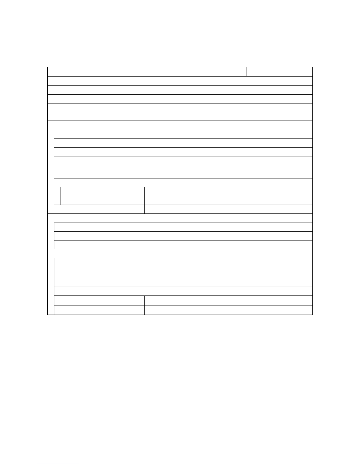
(A) Indoor Units
MODEL No. AD425CW
Source 220 - 230 - 240 V / 1 phase / 50Hz
Controller P.C.B. Ass’y CR-X363GS (Microprocessor)
Fan (Number…diameter) mm Centrifugal (2 … ø 190)
Fan motor
Model…Nominal output W KFG4X-71B5P … 70 W
Source 220 - 230 - 240 V / 1 phase / 50 Hz
No. of pole…r.p.m. (230 V, High) rpm. 4 … 1,063
Coil resistance Ω BRN – WHT : 74.72 ORG – YEL : 9.588
(Ambient temperature 20°C) WHT – VLT : 19.14 YEL – BLK : 10.52
VLT – ORG : 10.52 BLK – PNK : 21.72
Safety device
Operating temperature Open °C 130 ± 5
Close °C (115 ± 5 )
Run capacitor VAC, µF 450 VAC, 5 µF
Heat exchanger
Coil Aluminum plate fin / Copper tube
Rows…fin pitch mm 3… 1.7
Face area m
2
0.189
Drain pump PJV-1422
Rated VAC, W AC 230 V, 50 Hz, 12 W
Total head & capacity 500 mm, 400 cc/min
Page 31

– I-29 –
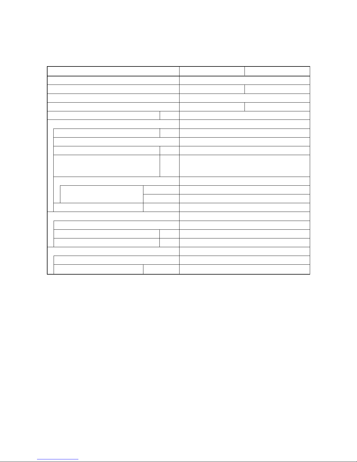
(A) Indoor Units
MODEL No. AD436CW
Source 220 - 230 - 240 V / 1 phase / 50Hz
Controller P.C.B. Ass’y CR-X363GS (Microprocessor)
Fan (Number…diameter) mm Centrifugal (3 … ø 190)
Fan motor
Model…Nominal output W KFC4X-141A5P…160 W
Source 220 - 230 - 240 V / 1 phase / 50 Hz
No. of pole…r.p.m. (230 V, High) rpm. 4 … 1,207
Coil resistance Ω BRN – WHT : 25.79
(Ambient temperature 20°C) WHT – VLT : 5.086
VLT – ORG : 8.626
ORG – YEL : 5.792
YEL – BLK : 6.746
PNK – VLT : 6.361
Safety device
Operating temperature Open °C 130 ± 5
Close °C ( 115 ± 5)
Run capacitor VAC, µF 450 VAC, 6 µF
Heat exchanger
Coil Aluminum plate fin / Copper tube
Rows…fin pitch mm 3… 2.0
Face area m
2
0.308
Drain pump PJV-1422
Rated VAC, W AC 230 V, 50 Hz, 12 W
Total head & capacity 500 mm, 400 cc/min
Page 32

– I-30 –
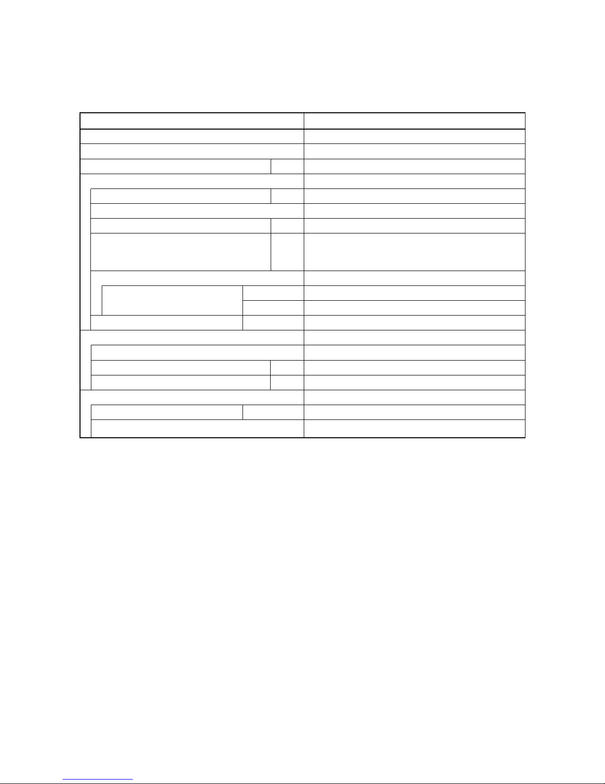
(A) Indoor Units
MODEL No. AD448CW
Source 220 - 230 - 240 V / 1 phase / 50Hz
Controller P.C.B. Ass’y CR-X363GS (Microprocessor)
Fan (Number…diameter) mm Centrifugal (3 … ø 190)
Fan motor
Model…Nominal output W KFC4X-141A5P…160 W
Source 220 - 230 - 240 V / 1 phase / 50 Hz
No. of pole…r.p.m. (230 V, High) rpm. 4 … 1,207
Coil resistance Ω BRN – WHT : 25.79
(Ambient temperature 20°C) WHT – VLT : 5.086
VLT – ORG : 8.626
ORG – YEL : 5.792
YEL – BLK : 6.746
ORG – VLT : 6.361
Safety device
Operating temperature Open °C 130 ± 5
Close °C ( 115 ± 5)
Run capacitor VAC, µF 450 VAC, 8 µF
Heat exchanger
Coil Aluminum plate fin / Copper tube
Rows…fin pitch mm 3… 2.0
Face area m
2
0.308
Drain pump PJV-1422
Rated VAC, W AC 230 V, 50 Hz, 12 W
Total head & capacity 500 mm, 400 cc/min
Page 33

– I-31 –
1-2 Major Component Specifications
(B) Outdoor Unit
MODEL No. AER525SCE
Source 220 - 230 - 240 V / 1 phase / 50 Hz
Controller P.C.B. Ass'y –
Control circuit fuse –
–
Compressor Rotary (Hermetic)
Model ..... number C - RN220H5B
Source 220 - 240 V / 1 phase / 50 Hz
Nominal output W 2200
Compressor oil cc 1500
Coil resistance Ω C – R : 0.76 , R – S : 3.52
(Ambient temperature 25 °C) C – S : 2.76
Safety devices
Overload relay models Internal type
Operating temperature Open °C 160 ± 5
Close °C87± 11
Crank case heater
Refrigerant amount at shipment kg R407C - 2.4
High pressure switch ACB-1TB07
Set pressure OFF kg/cm
2
32 (3.2 MPa)
ON kg/cm
2
24 ± 2.0 (2.4 ± 0.2 MPa)
Fan Propeller
Number...diameter mm 1 ..... ø460
Fan motor
Model KFC6T - 91C5P
Source 220 - 230 - 240 V / 1 phase / 50 Hz
No. of pole ..... rpm (230V, High / Med. / Low) 6...772 / 376 / 252
Nominal output W 70
Coil resistance Ω WHT – BRN : 127.3 , VLT – YEL : 15.0
(Ambient temperature 20°C) WHT – VLT : 56.7 , YEL – PNK : 7.2
Safety device Internal type
Operating temperature Open °C 130 ± 8
Close °C79± 15
Run capacitor VAC, µF 450 V, 6 µF
Heat exchange
Coil Aluminium plate fin / Copper tube
Rows ..... fin pitch mm 2 ..... 1.8
Face area m
2
0.616
+ 0
– 1.5
+ 0
– 0.15
Page 34

– I-32 –
1-2 Major Component Specifications
(B) Outdoor Unit
MODEL No. AER525SC3E
Source 380 - 400 - 415 V / 3 phase / 50 Hz
Controller P.C.B. Ass'y –
Control circuit fuse –
Compressor Rotary (Hermetic)
Model ..... number C - RN223H8D
Source 380 - 400 - 415 V / 3 phase / 50 Hz
Nominal output W 2400
Compressor oil cc 1350
Coil resistance Ω T – R : 5.77 , R – S : 5.66
(Ambient temperature 25 °C) S – T : 5.38
Safety devices
Overload relay models Internal type
Operating temperature Open °C 120 ± 5
Close °C98± 11
Crank case heater –
Refrigerant amount at shipment kg R407C - 2.4
High pressure switch ACB-1TB07
Set pressure OFF kg/cm
2
32 (3.2 MPa)
ON kg/cm
2
24 ± 2.0 (2.4 ± 0.2 MPa)
Fan Propeller
Number...diameter mm 1 ..... ø460
Fan motor
Model KFC6T - 91C5P
Source 220 - 230 - 240 V / 1 phase / 50 Hz
No. of pole ..... rpm (230V, High / Med. / Low) 6...772 / 376 / 252
Nominal output W 70
Coil resistance Ω WHT – BRN : 127.3 , VLT – YEL : 15.0
(Ambient temperature 20°C) WHT – VLT : 56.7 , YEL – PNK : 7.2
Safety device Internal type
Operating temperature Open °C 130 ± 8
Close °C79± 15
Run capacitor VAC, µF 450 V, 6 µF
Heat exchange
Coil Aluminium plate fin / Copper tube
Rows ..... fin pitch mm 2 ..... 1.8
Face area m
2
0.616
+ 0
– 1.5
+ 0
– 0.15
Page 35

– I-33 –
1-2 Major Component Specifications
(B) Outdoor Unit
MODEL No. AER525SCL3E
Source 380 - 400 - 415 V / 3 phase / 50 Hz
Controller P.C.B. Ass'y CR - CR254GL8 (Microprocessor)
Control circuit fuse 250 V, 3.15 A
Compressor Rotary (Hermetic)
Model ..... number C - RN223H8D
Source 380 - 400 - 415 V / 3 phase / 50 Hz
Nominal output W 2400
Compressor oil cc 1350
Coil resistance Ω T – R : 5.77 , R – S : 5.66
(Ambient temperature 25 °C) S – T : 5.38
Safety devices
Overload relay models Internal type
Operating temperature Open °C 120 ± 5
Close °C98± 11
Crank case heater 240V, 25W
Refrigerant amount at shipment kg R407C - 3.0
High pressure switch ACB-1TB07
Set pressure OFF kg/cm
2
32 (3.2 MPa)
ON kg/cm
2
24 ± 2.0 (2.4 ± 0.2 MPa)
Fan Propeller
Number...diameter mm 1 ..... ø460
Fan motor
Model KFC6T - 91C5P
Source 220 - 230 - 240 V / 1 phase / 50 Hz
No. of pole ..... rpm (230V, High / Med. / Low) 6...772 / 376 / 252
Nominal output W 70
Coil resistance Ω WHT – BRN : 127.3 , VLT – YEL : 15.0
(Ambient temperature 20°C) WHT – VLT : 56.7 , YEL – PNK : 7.2
Safety device Internal type
Operating temperature Open °C 130 ± 8
Close °C79± 15
Run capacitor VAC, µF 450 V, 6 µF
Heat exchange
Coil Aluminium plate fin / Copper tube
Rows ..... fin pitch mm 2 ..... 1.8
Face area m
2
0.616
+ 0
– 1.5
+ 0
– 0.15
Page 36

– I-34 –
1-2 Major Component Specifications
(B) Outdoor Unit
MODEL No. AER536SC3E AER548SC3E
Source 380 - 400 - 415 V / 3 phase / 50 Hz
Controller P.C.B. Ass'y –
Control circuit fuse –
Compressor Scroll (Hermetic)
Model ..... number C - SBN303H8A C - SBN373H8A
Source 380 - 400 - 415 V / 3 phase / 50 Hz
Nominal output W 2,400 3,700
Compressor oil cc 1,700 1,700
Coil resistance Ω T – R : 3.177 , R – S : 3.177 T – R : 2.806 , R – S : 2.806
(Ambient temperature 25 °C) S – T : 2.966 S – T : 2.651
Crank case heater – –
Safety devices
Overload relay models Internal type
Operating temperature Open °C155± 5 1455 ± 5
Close °C61± 961± 9
Refrigerant amount at shipment kg R407C - 4.0 R407C - 4.3
High pressure switch ACB-1TB07
Set pressure OFF kg/cm
2
32 (3.2 Mpa)
ON kg/cm
2
24 ± 2.0 (2.4 ± 0.2 Mpa)
Low pressure switch LCB-JA89
Set pressure OFF kg/cm
2
0.5 ± 0.3 (0.05 ± 0.03 Mpa)
ON kg/cm
2
1.5 ± 0.3 (0.15 ± 0.03 Mpa)
Fan Propeller
Number...diameter mm 2 ..... ø460
Fan motor
Model KFC6T - 91C5P 2
Source 220 - 230 - 240 V / 1 phase / 50 Hz
No. of pole ..... rpm (230V, High / Med. / Low) 6...772 / 376 / 252
Nominal output W 70 W 2
Coil resistance Ω BRN – WHT : 127.3 , VLT – YEL : 15.0
(Ambient temperature 20°C) WHT – VLT : 56.7 , YEL – PNK : 7.2
Safety device Internal type
Operating temperature Open °C 130 ± 8
Close °C79± 15
Run capacitor VAC, µF 450 V, 6 µF 2
Heat exchange
Coil Aluminium plate fin / Copper tube
Rows ..... fin pitch mm 2 ..... 2.0 2 ..... 1.8
Face area m
2
1.08
+ 0
– 1.5
+ 0
– 0.15
Page 37

– I-35 –
1-2 Major Component Specifications
(B) Outdoor Unit
MODEL No. AER536SCL3E AER548SCL3E
Source 380 - 400 - 415 V / 3 phase / 50 Hz
Controller P.C.B. Ass'y CR - CR254GL8 (Microprocessor)
Control circuit fuse 250 V, 3.15 A
Compressor Scroll (Hermetic)
Model ..... number C - SBN303H8A C - SBN373H8A
Source 380 - 400 - 415 V / 3 phase / 50 Hz
Nominal output W 2,400 3,700
Compressor oil cc 1,700 1,700
Coil resistance Ω T – R : 3.177 , R – S : 3.177 T – R : 2.806 , R – S : 2.806
(Ambient temperature 25 °C) S – T : 2.966 S – T : 2.651
Crank case heater 240 V, 32 W 240 V, 32 W
Safety devices
Overload relay models Internal type
Operating temperature Open °C155± 5 145 ± 5
Close °C61± 961± 9
Refrigerant amount at shipment kg R407C - 4.0 R407C - 4.3
High pressure switch ACB-1TB07
Set pressure OFF kg/cm
2
32 (3.2 Mpa)
ON kg/cm
2
24 ± 2.0 (2.4 ± 0.2 Mpa)
Low pressure switch LCB-JA89
Set pressure OFF kg/cm
2
0.5 ± 0.3 (0.05 ± 0.03 Mpa)
ON kg/cm
2
1.5 ± 0.3 (0.15 ± 0.03 Mpa)
Fan Propeller
Number...diameter mm 2 ..... ø460
Fan motor
Model KFC6T - 91C5P 2
Source 220 - 230 - 240 V / 1 phase / 50 Hz
No. of pole ..... rpm (230V, High / Med. / Low) 6...772 / 376 / 252
Nominal output W 70 W 2
Coil resistance Ω BRN – WHT : 127.3 , VLT – YEL : 15.0
(Ambient temperature 20°C) WHT – VLT : 56.7 , YEL – PNK : 7.2
Safety device Internal type
Operating temperature Open °C 1300 ± 8
Close °C79± 15
Run capacitor VAC, µF 450 V, 6 µF 2
Heat exchange
Coil Aluminium plate fin / Copper tube
Rows ..... fin pitch mm 2 ..... 2.0 2 ..... 1.8
Face area m
2
1.08
+ 0
– 1.5
+ 0
– 0.15
Page 38

– I-36 –
1-3 Other Component Specifications
AS425C AS436C AS448C
Power Transformer ATR - I75A
Rated
Primary
10.6 V, 0.93 A
AC 230 V, 50 Hz
Secondary
Capacity
9.85 VAC
Coil resistance Ω WHT – WHT : 96.5 , BRN – BRN : 0.8 (at 20°C)
Thermal cut off temperature °C 150
Thermistor (Coil sensor)
PBC - 41E - S36PBC - 41E - S26
Coil resistance kΩ –10 °C : 23.7 , 5 °C : 12.1
– 5 °C : 18.8 , 10 °C : 9.7
0 °C : 15.0 , 15 °C : 8.0
Drain pump WP20SL - 21
AC 230 V, 14.7 W
Rated
Float switch FC - 0218 - 103
Rated (Contact rated) AC 230V, 50W
Synchronized Moter M2LB24ZA12
Power Transformer ATR - I75A
Rated
Primary
10.6 V, 0.93 A
AC 230 V, 50 Hz
Secondary
Capacity
9.85 VAC
Coil resistance Ω WHT – WHT : 96.5 , BRN – BRN : 0.8 (at 20°C)
Thermal cut off temperature °C 150
Thermistor (Coil sensor)
PBC - 41E - S36
Thermistor (Room or coil sensor)
KTEC - 35 -S6
PBC - 41E - S26
Coil resistance kΩ
Coil resistance kΩ
–10 °C : 23.7 , 5 °C : 12.1
– 5 °C : 18.8 , 10 °C : 9.7
0 °C : 15.0 , 15 °C : 8.0
0 °C : 16.5 , 40 °C : 2.7
5 °C : 12.8 , 45 °C : 2.2
10 °C : 10.0 , 50 °C : 1.8
20 °C : 6.3 , 55 °C : 1.5
30 °C : 4.0 ,
Drain pump WP20SL - 21
AC 230 V, 14.7 W
Rated
Float switch FC - 0218 - 103
Rated (Contact rated) AC 230V, 50W
Synchronized Moter M2LB24ZA12
Indicator Lamp Ass'y IND - X253GS IND - X363GS, X483GS
Switch Ass'y SW - X363GS
(A) Indoor Unit
AS425C AS436C AS448C
Page 39

– I-37 –
Power Transformer
MODEL No.
MODEL No.
ATR - I75B
Rated
Primary
10.6 V, 0.93 A
AC 230 V, 50 Hz
Secondary
Capacity
9.86 VAC
Coil resistance Ω WHT – WHT : 101 , BRN – BRN : 0.6 (at 20°C)
Thermal cut off temperature °C 150
Thermistor (Coil sensor)
PBC - 41E - S14
Coil resistance kΩ –10 °C : 23.7 , 5 °C : 12.1
– 5 °C : 18.8 , 10 °C : 9.7
0 °C : 15.0 , 15 °C : 8.0
Synchronized Moter MT8 - 3C
Power Transformer ATR - I75B
Rated
Primary
10.6 V, 0.93 A
AC 230 V, 50 Hz
Secondary
Capacity
9.86 VAC
Coil resistance Ω WHT – WHT : 101 , BRN – BRN : 0.6 (at 20°C)
Thermal cut off temperature °C 150
Thermistor (Coil sensor)
PBC - 41E - S14
Thermistor (Room or coil sensor)
KTEC - 35 -S6
Coil resistance kΩ
Coil resistance kΩ
–10 °C : 23.7 , 5 °C : 12.1
– 5 °C : 18.8 , 10 °C : 9.7
0 °C : 15.0 , 15 °C : 8.0
0 °C : 16.5 , 40 °C : 2.7
5 °C : 12.8 , 45 °C : 2.2
10 °C : 10.0 , 50 °C : 1.8
20 °C : 6.3 , 55 °C : 1.5
30 °C : 4.0 ,
Synchronized Moter MT8 - 3C
Indicator Lamp Ass'y IND - T251GS
Switch Ass'y SW - X363GS
(A) Indoor Unit
AC425C AC436C AC448C
AC425C AC436C AC448C
Page 40

– I-38 –
AD425CW - 448CW
Power Transformer
MODEL NO.
ATR - I75B
Rated
VAC, Hz
Indoor Unit
10.6 V, 0.93 A
230 V, 50Hz
Primary
Secondary
9.85 VAC
Coil resistance Ω WHT – WHT : 96.5 , BRN – BRN : 0.8
Thermal cut off temperature °C 150
Thermistor (Coil sensor) : TH1
PBC - 41E - S36
Resistance kΩ –10 °C : 23.7 ± 5% , 5 °C : 12.1 ± 5%
– 5 °C : 18.8 ± 5% , 10 °C : 9.7 ± 5%
0 °C : 15.0 ± 5% ,
Drain pump PTV-1422
AC 230 V, 12 W
Rated
Float switch FS-0218-103
Rated (Contact rated) DC 12V, 25W
(A) Indoor Units
Page 41

– I-39 –
1-3 Other Component Specifications
(B) Outdoor Unit
MODEL No. AER525SCE
Compressor Motor Mgnetic Contactor FC - 1SZ607
Coil rated AC 220 - 240 V, 50 Hz
Coil resistance (at 20°C) Ω 828 ± 15 %
Contact rated V, A AC 440 V, 13A
Auxiliary relay HH62S
Coil rated AC 240 V, 50 Hz
Coil resistance (at 20°C) kΩ 17.2
Contact rated V, A AC 220 V, 5A
Thermostat (Coil sensor) YTB - S377
Operating Temperature °C 27.5 ± 1.5 OFF (High)
25.5 ON (Low)
Contact rated A AC 250 V, 1 A
+1.5
–0.5
Page 42

– I-40 –
(B) Outdoor Unit
MODEL No. AER525SC3E AER536SC3E AER548SC3E
Compressor Motor Mgnetic Contactor FW - 1SZ607A
Coil rated AC 220 - 240 V, 50 Hz
Coil resistance (at 20°C) Ω 828 ± 15 %
Contact rated V, A AC 440 V, 13A
Auxiliary relay RDR - S400
Coil rated AC 240 V, 50 Hz
Coil resistance (at 20°C) kΩ 17.2
Contact rated V, A AC 220 V, 5A
Thermostat (Coil sensor) YTB - S377
Operating Temperature °C 27.5 ± 1.5 OFF (High)
25.5 ON (Low)
Contact rated A AC 250 V, 1 A
+1.5
–0.5
MODEL No. AER525SCL3E AER536SCL3E AER548SCL3E
Compressor Motor Magnetic Contactor FW - 1SZ607A
Coil rated AC 220 - 240 V, 50 Hz
Coil resistance (at 20°C) Ω 828 (at 20 °C)
Contact rated V, A AC 440 V, 13 A
Thermal Relay
Contact rated V, A AC 220 V, 2.25 A
Rated ampere (90 / 120%) A 6 A, 110%
29.0 or more (H)
18.0 or more (M)
10.0 or more (L)
less than 10.0 (LL)
29.0 or more (H)
20.0 or more (M)
8.0 or more (L)
less than 8.0 (LL)
27.0 or more (H)
12.0 or more (M)
–2.0 or more (L)
less than –2.0 (LL)
10 A, 90% 10 A, 110%
Auxiliary relay HH62S
Coil rated A AC 240 V, 50 Hz
Coil resistance kW 15.5 ± 20 %
Contact rated A AC 250 V, 10A
Thermostat (Coil sensor) PBC - 41E - S26
Operating Temperature °C
Page 43

– I-41 –
1-4 Dimensional Data
(A) Indoor Units : 4-Way Air Discharge Semi-concealed Type
25 Type
860
100
760
500
500
298
30
205
165
12
12
48
860
820 (Ceiling opening)
820 (Ceiling opening)
61
730 (Suspention bolt pitch)
Panel center
590 (Suspention bolt pitch)
345 35
Air intake grille
Air outlet
Refrigerant liquid line [ø 9.52 (In case of 25 type,
use the tube connector.)]
Refrigerant gas line
ø 12.7: 12 type, ø 15.88: 18, 25 type
Drain connection
Power supply entry
For discharge duct
Humidifier (option) mounting hole
Suspension bolt mounting
342 15
X-view
1488_X_I
125
207
100
205
61
760
50 150
255
207
9
9
Page 44

– I-42 –
(A) Indoor Units : 4-Way Air Discharge Semi-concealed Type
36, 48 Type
1150
1050
790
500
328
30
218
125
860
1110 (Ceiling opening)
820 (Ceiling opening)
61
1020 (Suspention bolt pitch)
Panel center
590 (Suspention bolt pitch)
490 40
Air intake grille
Air outlet
Refrigerant liquid line (ø9.52)
Refrigerant gas line (ø19.05)
Drain connection
Power supply entry
For discharge duct
Humidifier (option) mounting hole
Suspension bolt mounting
X-view
0183_X_I
218
14535
210
60
760
70 165
285
210
100 100
9
9
342 15
12
48
12
Page 45

– I-43 –
Drain connection
Drain connection for left side
Refrigerant liquid line (ø9.52)
Refrigerant gas line (18, 25 type: ø15.88 / 36, 48 type: ø19.05)
Hole for rear side refrigerant tubing
Hole for through-the-wall refrigerant tubing (ø100 hole)
Hole for upper side refrigerant tubing (Knockout hole)
Hole for right side refrigerant tubing (Knockout hole)
Hole for left side drain connection (Knockout hole)
Hole for power supply cord (Knockout hole ø40)
Hole for remote controller wiring
1394_X_S
Dimension : mm
Air intake
Air outlet
500 or more
Hole for wall-through piping (View from front)
17081
N
214
A
670
280
280
B
D
320 160
E
L
M
K
F
G
H
28160
53
JI
146
183
103
251
141
35C (Suspension bolt hole pitch)
89
147
71132
280
86
Front
(Service space)(Service space)
Holes in the rear unit (View from front)
(Suspension bolt hole pitch)
250
or more
250
or more
ABCDEFGHIJKLMN
25 type 1,300 1,280 1,230 147 101 64 134 147 116 83 120 95 147 190
36, 48 type 1,575 1,5551,505 197 151 114 184 197 121 80 170 140 197 240
(A) Indoor Units : Ceiling Mounted Type
25, 36, 48 Type
Page 46

– I-44 –
(A) Indoor Units : Concealed Duct Type
25 Type
Refrigerant liquid line ø9.52 (narrow tube)
(Use the tube connector)
Refrigerant gas line ø15.88 (wide tube)
Upper drain port (O.D. 32 mm)
Bottom drain port (O.D. 26 mm)
Suspension lug
Power supply outlet (2-ø30)
Fresh air intake port (ø150)
Flange for the flexible air outlet duct (ø200)
Tube cover
Electrical component box
Flange for the air intake duct
(Option or field supply)
9
10
11
1731_U_I
(Suspension bolt pitch)
16-ø3.3
(Hole)
962 (Air outlet duct flange)
900
1000
1080 (Suspension bolt pitch)
(150)
40
290 290 272 75
65
90
180
3131
185
580
25
115
19
Inspection access
(450 × 450)
(Field supply)
10
285
70 130
25 210
310
25
175
35
190
85
25
7030
160
630
25
10
11
24
260
(Air outlet
duct flange)
Page 47

– I-45 –
(A) Indoor Units : Concealed Duct Type
36, 48 Type
Refrigerant liquid line ø9.52 (narrow tube)
Refrigerant gas line ø19.05 (wide tube)
Upper drain port (O.D. 32 mm)
Bottom drain port (O.D. 26 mm)
Suspension lug
Power supply outlet (2-ø30)
Fresh air intake port (ø150)
Flange for the flexible air outlet duct (ø200)
Tube cover
Electrical component box
Flange for the air intake duct
(Option or field supply)
9
10
11
1732_U_I
(Suspension bolt pitch)
18-ø3.3
(Hole)
1442 (Air outlet duct flange)
230 P
×
6 = 1380
1480
1560 (Suspension bolt pitch)
(150)
40
335 335 335 310 75
65
90
230
3131
185
580
25
115
19
Inspection access
(450 × 450)
(Field supply)
10
285
70 130
25 210
310
25
175
35
190
85
25
7030
160
630
25
10
11
24
260
(Air outlet
duct flange)
Page 48

– I-46 –
Flange for the air intake duct (Field supply)
: For Concealed Duct Type
2-ø3.3
10
18
31
FG
HGF9
E
D
B (O.D.)
A
25
(Hole)
C-ø3.3
(Hole)
I-ø6
(Hole)
210
305
260 (O.D.) 23
2004584
45
25
25
10
1766_U_I
ABCD E F G HI
9, 12, 18 type 698 662 4 200 3 200P = 600 170 – 340 12
25 type 998 962 6 180 5 180P = 900 120 245 (245 1) 250 16
36, 48 type 1,478 1,442 7 230 6 230P = 1,380 120 490 (245 2) 240 20
(mm)
Page 49

– I-47 –
(B)Outdoor Units :AER525SCE, AER525SC3E, AER525SCL3E
735
280
307
940
Dimension : mm
Hole for anchor bolt (4-ø13)
Refrigerant tube joint (narrow tube)
Flare connection 1/4 in (6.35 mm)
Refrigerant tube joint (wide tube)
Flare connection 5/8 in (15.88 mm)
Refrigerant tubing inlet
Power supply inlet
400
380 10
30
50 50
340
110660170
Page 50

– I-48 –
(B)Outdoor Units :AER536SC3E, AER536SCL3E
AER548SC3E, AER548SCL3E
1235
580
607
940
Dimension : mm
Hole for anchor bolt (4-ø13)
Refrigerant tube joint (narrow tube)
Flare connection 3/8 in (9.52 mm)
Refrigerant tube joint (wide tube)
Flare connection 3/4 in (19.05 mm)
Refrigerant tubing inlet
Power supply inlet
400
380 10
30
50 50
340
110660170
Page 51

– I-49 –
HP
High
pressure
switch
Compressor
Accumulator
EC
P
Heat exchanger
EC
P
Heat exchanger
Distributor
Capillary
tube
Strainer
Liquid line
nipple
Liquid line
service
valve
O.D.
ø6.35mm
(1/4")
O.D.
ø15.88mm
(5/8")
Gas line
nipple
Gas line
service
valve
Cooling Cycle
1-5 Refrigerant Flow Diagram
Outdoor Units : AER525SCE
AER525SC3E
Indoor Unit : 25 Type
Page 52

– I-50 –
HP
High
pressure
switch
Compressor
Accumulator
Accumulator
EC
P
Heat exchanger
Solenoid valve
EC
P
Heat exchanger
Distributor
Strainer
Liquid line
nipple
Liquid line
service
valve
O.D.
ø6.35mm
(1/4")
( )
O.D.
ø15.88mm
(5/8")
Gas line
nipple
Gas line
service
valve
Cooling Cycle
Capillary
tube
1549_C_S
1-5 Refrigerant Flow Diagram
Outdoor Units : AER525SCL3E
Indoor Unit : 25 Type
S
Page 53

– I-51 –
HP
High
pressure
switch
Compressor
Accumulator
EC
P
Heat exchanger
EC
P
Heat exchanger
Distributor
Strainer
Liquid line
nipple
Liquid line
service
valve
O.D.
ø9.52mm
(3/8")
O.D.
ø19.05mm
(3/4")
Gas line
nipple
Gas line
service
valve
Cooling Cycle
Cooling
Maximum 35°C DB / 23°C WB
19°C DB / 14°C WB –15°C DB (EL Type), 19°C DB (E Type)
43°C DB
Minimum
Capillary
tube
1550_C_S
LP
Low pressure switch
1-5 Refrig
1-6 Operating Range
erant Flow Diagram
Outdoor Units : AER536SC(L)3E
AER548SC(L)3E
Indoor Units : 36, 48 Type
Temperature Indoor aire intake temp. Outdoor air intake temp.
Page 54

– I-52 –
1-7 Cooling Capacity
Indoor Unit : AS425C Outdoor Unit : AER525SCE
TC : Total Cooling Capacity (kW)
SHC : Sensible Heat Capacity (kW)
CI : Compressor Input (kW)
Rating conditions are
: Outdoor Ambient Temp. 35 °C DB
: Indoor Unit Entering Air Temp. 27 °C DB / 19 °C WB
RATING CAPACITY : 7.3 kW AIR FLOW RATE : 1140 CMH
EVAPORATOR CONDENSER
ENT. TEMP. °C AMBIENT TEMP °C
WB DB 25 30 35 40 43
TC 6.95 6.68 6.40 6.15 5.99
CI 2.24 2.37 2.49 2.60 2.65
21 SHC 4.6 4.5 4.4 4.2 4.1
15 23 SHC 5.2 5.1 4.9 4.8 4.7
25 SHC 5.8 5.6 5.5 5.3 5.3
27 SHC 6.3 6.2 6 5.9 5.8
29 SHC 6.9 6.68 6.4 6.15 5.99
31 SHC 6.95 6.68 6.4 6.15 5.99
TC 7.45 7.15 6.85 6.58 6.41
CI 2.30 2.43 2.55 2.67 2.72
21 SHC 4.1 3.9 3.8 3.7 3.6
17 23 SHC 4.6 4.5 4.3 4.2 4.1
25 SHC 5.2 5 4.9 4.8 4.7
27 SHC 5.7 5.6 5.5 5.3 5.2
29 SHC 6.3 6.2 6 5.9 5.8
31 SHC 6.9 6.7 6.6 6.4 6.4
TC 7.93 7.61 # 7.3 7.01 6.83
CI 2.07 2.35 2.63 2.91 3.08
21 SHC 3.5 3.3 3.2 3.1 3
19 23 SHC 4 3.9 3.7 3.6 3.5
25 SHC 4.6 4.4 4.3 4.2 4.1
27 SHC 5.1 5 4.9 4.7 4.7
29 SHC 5.7 5.6 5.4 5.3 5.2
31 SHC 6.3 6.1 6 5.8 5.8
TC 8.41 8.08 7.75 7.44 7.24
CI 2.43 2.58 2.70 2.82 2.88
23 SHC 3.4 3.3 3.1 3 2.9
21 25 SHC 4 3.8 3.7 3.6 3.5
27 SHC 4.5 4.4 4.2 4.1 4
29 SHC 5.1 4.9 4.8 4.7 4.6
31 SHC 5.6 5.5 5.4 5.2 5.2
TC 8.91 8.56 8.21 7.88 7.67
CI 2.50 2.65 2.77 2.90 2.96
23 25 SHC 3.3 3.2 3.1 2.9 2.9
27 SHC 3.9 3.8 3.6 3.5 3.4
29 SHC 4.5 4.3 4.2 4.1 4
31 SHC 5 4.9 4.7 4.6 4.5
TC 9.40 9.03 8.66 8.31 8.10
CI 2.57 2.72 2.85 2.98 3.04
25 27 SHC 3.2 3.1 3 2.8 2.8
29 SHC 3.8 3.7 3.5 3.4 3.3
31 SHC 4.3 4.2 4.1 4 3.9
Page 55

– I-53 –
1-7 Cooling Capacity
Indoor Unit : AS425C Outdoor Unit : AER525SC(L)3E
TC : Total Cooling Capacity (kW)
SHC : Sensible Heat Capacity (kW)
CI : Compressor Input (kW)
Rating conditions are
: Outdoor Ambient Temp. 35
°
C DB
: Indoor Unit Entering Air Temp. 27
°
C DB / 19 °C WB
RATING CAPACITY : 7.3 kW AIR FLOW RATE : 1140 CMH
EVAPORATOR CONDENSER
ENT. TEMP. °C AMBIENT TEMP °C
WB DB 25 30 35 40 43
TC 6.95 6.68 6.40 6.15 5.99
CI 2.15 2.28 2.39 2.50 2.55
21 SHC 4.6 4.5 4.4 4.2 4.1
15 23 SHC 5.2 5.1 4.9 4.8 4.7
25 SHC 5.8 5.6 5.5 5.3 5.3
27 SHC 6.3 6.2 6 5.9 5.8
29 SHC 6.9 6.68 6.4 6.15 5.99
31 SHC 6.95 6.68 6.4 6.15 5.99
TC 7.45 7.15 6.85 6.58 6.41
CI 2.21 2.34 2.45 2.57 2.61
21 SHC 4.1 3.9 3.8 3.7 3.6
17 23 SHC 4.6 4.5 4.3 4.2 4.1
25 SHC 5.2 5 4.9 4.8 4.7
27 SHC 5.7 5.6 5.5 5.3 5.2
29 SHC 6.3 6.2 6 5.9 5.8
31 SHC 6.9 6.7 6.6 6.4 6.4
TC 7.93 7.61 # 7.3 7.01 6.83
CI 1.99 2.26 2.53 2.80 2.96
21 SHC 3.5 3.3 3.2 3.1 3
19 23 SHC 4 3.9 3.7 3.6 3.5
25 SHC 4.6 4.4 4.3 4.2 4.1
27 SHC 5.1 5 4.9 4.7 4.7
29 SHC 5.7 5.6 5.4 5.3 5.2
31 SHC 6.3 6.1 6 5.8 5.8
TC 8.41 8.08 7.75 7.44 7.24
CI 2.34 2.48 2.60 2.72 2.77
23 SHC 3.4 3.3 3.1 3 2.9
21 25 SHC 4 3.8 3.7 3.6 3.5
27 SHC 4.5 4.4 4.2 4.1 4
29 SHC 5.1 4.9 4.8 4.7 4.6
31 SHC 5.6 5.5 5.4 5.2 5.2
TC 8.91 8.56 8.21 7.88 7.67
CI 2.40 2.55 2.67 2.79 2.84
23 25 SHC 3.3 3.2 3.1 2.9 2.9
27 SHC 3.9 3.8 3.6 3.5 3.4
29 SHC 4.5 4.3 4.2 4.1 4
31 SHC 5 4.9 4.7 4.6 4.5
TC 9.40 9.03 8.66 8.31 8.10
CI 2.47 2.62 2.75 2.87 2.92
25 27 SHC 3.2 3.1 3 2.8 2.8
29 SHC 3.8 3.7 3.5 3.4 3.3
31 SHC 4.3 4.2 4.1 4 3.9
Page 56

– I-54 –
1-7 Cooling Capacity
Indoor Unit : AS436C Outdoor Unit : AER536SC(L)3E
TC : Total Cooling Capacity (kW)
SHC : Sensible Heat Capacity (kW)
CI : Compressor Input (kW)
Rating conditions are
: Outdoor Ambient Temp. 35
°
C DB
: Indoor Unit Entering Air Temp. 27
°
C DB / 19 °C WB
RATING CAPACITY : 10.6 kW AIR FLOW RATE : 1920 CMH
EVAPORATOR CONDENSER
ENT. TEMP. °C AMBIENT TEMP °C
WB DB 25 30 35 40 43
TC 10.09 9.70 9.30 8.93 8.69
CI 3.17 3.36 3.52 3.68 3.74
21 SHC 7 6.8 6.6 6.4 6.3
15 23 SHC 7.9 7.7 7.5 7.3 7.2
25 SHC 8.8 8.6 8.5 8.3 8.2
27 SHC 9.8 9.6 9.3 8.93 8.69
29 SHC 10.09 9.7 9.3 8.93 8.69
31 SHC 10.09 9.7 9.3 8.93 8.69
TC 10.81 10.38 9.95 9.55 9.31
CI 3.25 3.44 3.61 3.77 3.84
21 SHC 6 5.8 5.6 5.5 5.4
17 23 SHC 7 6.8 6.6 6.4 6.3
25 SHC 7.9 7.7 7.5 7.3 7.2
27 SHC 8.8 8.6 8.4 8.3 8.1
29 SHC 9.8 9.6 9.4 9.2 9.1
31 SHC 10.7 10.38 9.95 9.55 9.31
TC 11.51 11.06 # 10.6 10.18 9.91
CI 2.93 3.33 3.72 4.11 4.35
21 SHC 5 4.8 4.6 4.5 4.4
19 23 SHC 6 5.8 5.6 5.4 5.3
25 SHC 6.9 6.7 6.5 6.3 6.2
27 SHC 7.8 7.6 7.4 7.3 7.2
29 SHC 8.8 8.6 8.4 8.2 8.1
31 SHC 9.7 9.5 9.3 9.1 9
TC 12.21 11.73 11.25 10.80 10.52
CI 3.44 3.65 3.82 4.00 4.07
23 SHC 4.9 4.8 4.6 4.4 4.3
21 25 SHC 5.9 5.7 5.5 5.3 5.2
27 SHC 6.8 6.6 6.4 6.2 6.1
29 SHC 7.7 7.6 7.4 7.2 7.1
31 SHC 8.7 8.5 8.3 8.1 8
TC 12.94 12.42 11.91 11.44 11.14
CI 3.53 3.74 3.92 4.10 4.18
23 25 SHC 4.8 4.6 4.5 4.3 4.2
27 SHC 5.8 5.6 5.4 5.2 5.1
29 SHC 6.7 6.5 6.3 6.1 6
31 SHC 7.6 7.4 7.3 7.1 7
TC 13.65 13.11 12.57 12.07 11.76
CI 3.63 3.85 4.04 4.22 4.30
25 27 SHC 4.7 4.5 4.3 4.2 4.1
29 SHC 5.6 5.4 5.3 5.1 5
31 SHC 6.6 6.4 6.2 6 5.9
Page 57

– I-55 –
TC : Total Cooling Capacity (kW)
SHC : Sensible Heat Capacity (kW)
CI : Compressor Input (kW)
Rating conditions are
: Outdoor Ambient Temp. 35
°
C DB
: Indoor Unit Entering Air Temp. 27
°
C DB / 19
°
C WB
RATING CAPACITY : 12.6 kW AIR FLOW RATE : 1920 CMH
EVAPORATOR CONDENSER
ENT. TEMP. °C AMBIENT TEMP °C
WB DB 25 30 35 40 43
TC 12.00 11.53 11.05 10.61 10.33
CI 3.67 3.89 4.07 4.26 4.34
21 SHC 8 7.7 7.5 7.2 7.1
15 23 SHC 8.9 8.7 8.4 8.2 8
25 SHC 9.8 9.6 9.3 9.1 9
27 SHC 10.8 10.5 10.3 10 9.9
29 SHC 11.7 11.4 11.05 10.61 10.33
31 SHC 12 11.53 11.05 10.61 10.33
TC 12.85 12.34 11.83 11.35 11.06
CI 3.76 3.99 4.18 4.37 4.45
21 SHC 7 6.8 6.5 6.3 6.2
17 23 SHC 8 7.7 7.5 7.2 7.1
25 SHC 8.9 8.6 8.4 8.2 8
27 SHC 9.8 9.6 9.3 9.1 9
29 SHC 10.8 10.5 10.3 10 9.9
31 SHC 11.7 11.4 11.2 11 10.8
TC 13.68 13.14 # 12.6 12.10 11.78
CI 3.40 3.86 4.31 4.76 5.04
21 SHC 6 5.8 5.5 5.3 5.2
19 23 SHC 6.9 6.7 6.5 6.2 6.1
25 SHC 7.9 7.6 7.4 7.2 7
27 SHC 8.8 8.6 8.3 8.1 8
29 SHC 9.7 9.5 9.2 9 8.9
31 SHC 10.7 10.4 10.2 10 9.8
TC 14.52 13.95 13.37 12.84 12.50
CI 3.99 4.23 4.43 4.63 4.72
23 SHC 5.9 5.7 5.4 5.2 5.1
21 25 SHC 6.8 6.6 6.4 6.1 6
27 SHC 7.8 7.5 7.3 7.1 6.9
29 SHC 8.7 8.5 8.2 8 7.9
31 SHC 9.6 9.4 9.1 8.9 8.8
TC 15.38 14.77 14.16 13.60 13.24
CI 4.09 4.34 4.55 4.75 4.84
23 25 SHC 5.8 5.5 5.3 5.1 4.9
27 SHC 6.7 6.5 6.2 6 5.9
29 SHC 7.6 7.4 7.2 6.9 6.8
31 SHC 8.6 8.3 8.1 7.9 7.7
TC 16.23 15.59 14.94 14.35 13.97
CI 4.21 4.46 4.68 4.89 4.98
25 27 SHC 5.6 5.4 5.1 4.9 4.8
29 SHC 6.5 6.3 6.1 5.9 5.7
31 SHC 7.5 7.2 7 6.8 6.7
1-7 Cooling Capacity
Indoor Unit : AS448C Outdoor Unit : AER548SC(L)3E
Page 58

– I-56 –
TC : Total Cooling Capacity (kW)
SHC : Sensible Heat Capacity (kW)
CI : Compressor Input (kW)
Rating conditions are
: Outdoor Ambient Temp. 35
°
C DB
: Indoor Unit Entering Air Temp. 27
°
C DB / 19 °C WB
RATING CAPACITY : 7.3 kW AIR FLOW RATE : 1080 CMH
EVAPORATOR CONDENSER
ENT. TEMP. °C AMBIENT TEMP °C
WB DB 25 30 35 40 43
TC 6.95 6.68 6.40 6.15 5.99
CI 2.24 2.37 2.49 2.60 2.65
21 SHC 4.7 4.5 4.4 4.3 4.2
15 23 SHC 5.2 5.1 5 4.8 4.7
25 SHC
5.8
5.7 5.5 5.4 5.3
27 SHC
6.4
6.2 6.1 6 5.9
29 SHC 6.9 6.68 6.4 6.15 5.99
31 SHC 6.95 6.68 6.4 6.15 5.99
TC 7.45 7.15 6.85 6.58 6.41
CI 2.30 2.43 2.55 2.67 2.72
21 SHC 4.1 4 3.8 3.7 3.6
17 23 SHC 4.7 4.5 4.4 4.3 4.2
25 SHC 5.2 5.1 4.9 4.8 4.7
27 SHC 5.8 5.7 5.5 5.4 5.3
29 SHC 6.4 6.2 6.1 5.9 5.9
31 SHC 6.9 6.8 6.6 6.5 6.4
TC 7.93 7.61 # 7.3 7.01 6.83
CI 2.07 2.35 2.63 2.91 3.08
21 SHC 3.5 3.4 3.2 3.1 3
19 23 SHC 4.1 3.9 3.8 3.6 3.6
25 SHC 4.6 4.5 4.3 4.2 4.1
27 SHC 5.2 5 4.9 4.8 4.7
29 SHC 5.8 5.6 5.5 5.3 5.3
31 SHC 6.3 6.2 6 5.9 5.8
TC 8.41 8.08 7.75 7.44 7.24
CI 2.43 2.58 2.70 2.82 2.88
23 SHC 3.4 3.3 3.2 3 3
21 25 SHC 4 3.9 3.7 3.6 3.5
27 SHC 4.6 4.4 4.3 4.2 4.1
29 SHC 5.1 5 4.8 4.7 4.6
31 SHC 5.7 5.6 5.4 5.3 5.2
TC 8.91 8.56 8.21 7.88 7.67
CI 2.50 2.65 2.77 2.90 2.96
23 25 SHC 3.4 3.2 3.1 3 2.9
27 SHC 3.9 3.8 3.6 3.5 3.4
29 SHC 4.5 4.3 4.2 4.1 4
31 SHC 5.1 4.9 4.8 4.7 4.6
TC 9.40 9.03 8.66 8.31 8.10
CI 2.57 2.72 2.85 2.98 3.04
25 27 SHC 3.3 3.1 3 2.9 2.8
29 SHC 3.8 3.7 3.6 3.4 3.4
31 SHC 4.4 4.3 4.1 4 3.9
1-7 Cooling Capacity
Indoor Unit : AC425C Outdoor Unit : AER525SCE
Page 59

– I-57 –
TC : Total Cooling Capacity (kW)
SHC : Sensible Heat Capacity (kW)
CI : Compressor Input (kW)
Rating conditions are
: Outdoor Ambient Temp. 35
°
C DB
: Indoor Unit Entering Air Temp. 27
°
C DB / 19 °C WB
RATING CAPACITY : 7.3 kW AIR FLOW RATE : 1080 CMH
EVAPORATOR CONDENSER
ENT. TEMP. °C AMBIENT TEMP °C
WB DB 25 30 35 40 43
TC 6.95 6.68 6.40 6.15 5.99
CI 2.15 2.28 2.39 2.50 2.55
21 SHC 4.7 4.5 4.4 4.3 4.2
15 23 SHC 5.2 5.1 5 4.8 4.7
25 SHC 5.8 5.7 5.5 5.4 5.3
27 SHC 6.4 6.2 6.1 6 5.9
29 SHC 6.9 6.68 6.4 6.15 5.99
31 SHC 6.95 6.68 6.4 6.15 5.99
TC 7.45 7.15 6.85 6.58 6.41
CI 2.21 2.34 2.45 2.57 2.61
21 SHC 4.1 4 3.8 3.7 3.6
17 23 SHC 4.7 4.5 4.4 4.3 4.2
25 SHC 5.2 5.1 4.9 4.8 4.7
27 SHC 5.8 5.7 5.5 5.4 5.3
29 SHC 6.4 6.2 6.1 5.9 5.9
31 SHC 6.9 6.8 6.6 6.5 6.4
TC 7.93 7.61 # 7.3 7.01 6.83
CI 1.99 2.26 2.53 2.80 2.96
21 SHC 3.5 3.4 3.2 3.1 3
19 23 SHC 4.1 3.9 3.8 3.6 3.6
25 SHC 4.6 4.5 4.3 4.2 4.1
27 SHC 5.2 5 4.9 4.8 4.7
29 SHC 5.8 5.6 5.5 5.3 5.3
31 SHC 6.3 6.2 6 5.9 5.8
TC 8.41 8.08 7.75 7.44 7.24
CI 2.34 2.48 2.60 2.72 2.77
23 SHC 3.4 3.3 3.2 3 3
21 25 SHC 4 3.9 3.7 3.6 3.5
27 SHC 4.6 4.4 4.3 4.2 4.1
29 SHC 5.1 5 4.8 4.7 4.6
31 SHC 5.7 5.6 5.4 5.3 5.2
TC 8.91 8.56 8.21 7.88 7.67
CI 2.40 2.55 2.67 2.79 2.84
23 25 SHC 3.4 3.2 3.1 3 2.9
27 SHC 3.9 3.8 3.6 3.5 3.4
29 SHC 4.5 4.3 4.2 4.1 4
31 SHC 5.1 4.9 4.8 4.7 4.6
TC 9.40 9.03 8.66 8.31 8.10
CI 2.47 2.62 2.75 2.87 2.92
25 27 SHC 3.3 3.1 3 2.9 2.8
29 SHC 3.8 3.7 3.6 3.4 3.4
31 SHC 4.4 4.3 4.1 4 3.9
1-7 Cooling Capacity
Indoor Unit : AC425C Outdoor Unit : AER525SC(L)3E
Page 60

– I-58 –
1-7 Cooling Capacity
Indoor Unit : AC436C Outdoor Unit : AER536SC(L)3E
TC : Total Cooling Capacity (kW)
SHC : Sensible Heat Capacity (kW)
CI : Compressor Input (kW)
Rating conditions are
: Outdoor Ambient Temp. 35
°
C DB
: Indoor Unit Entering Air Temp. 27
°
C DB / 19 °C WB
RATING CAPACITY : 10.6 kW AIR FLOW RATE : 1800 CMH
EVAPORATOR CONDENSER
ENT. TEMP. °C AMBIENT TEMP °C
WB DB 25 30 35 40 43
TC 10.09 9.70 9.30 8.93 8.69
CI 3.17 3.36 3.52 3.68 3.74
21 SHC 7.1 6.9 6.7 6.5 6.4
15 23 SHC 8 7.8 7.6 7.5 7.4
25 SHC 9 8.8 8.6 8.4 8.3
27 SHC 10 9.7 9.3 8.93 8.69
29 SHC 10.09 9.7 9.3 8.93 8.69
31 SHC 10.09 9.7 9.3 8.93 8.69
TC 10.81 10.38 9.95 9.55 9.31
CI 3.25 3.44 3.61 3.77 3.84
21 SHC 6.1 5.9 5.7 5.5 5.4
17 23 SHC 7 6.8 6.7 6.5 6.4
25 SHC 8 7.8 7.6 7.4 7.3
27 SHC 9 8.8 8.6 8.4 8.3
29 SHC 9.9 9.8 9.6 9.4 9.3
31 SHC 10.81 10.38 9.95 9.55 9.31
TC 11.51 11.06 # 10.6 10.18 9.91
CI 2.93 3.33 3.72 4.11 4.35
21 SHC 5 4.8 4.7 4.5 4.4
19 23 SHC 6 5.8 5.6 5.5 5.3
25 SHC 7 6.8 6.6 6.4 6.3
27 SHC 7.9 7.8 7.6 7.4 7.3
29 SHC 8.9 8.7 8.5 8.4 8.2
31 SHC 9.9 9.7 9.5 9.3 9.2
TC 12.21 11.73 11.25 10.80 10.52
CI 3.44 3.65 3.82 4.00 4.07
23 SHC 5 4.8 4.6 4.4 4.3
21 25 SHC 5.9 5.7 5.5 5.4 5.3
27 SHC 6.9 6.7 6.5 6.3 6.2
29 SHC 7.9 7.7 7.5 7.3 7.2
31 SHC 8.8 8.6 8.4 8.3 8.2
TC 12.94 12.42 11.91 11.44 11.14
CI 3.53 3.74 3.92 4.10 4.18
23 25 SHC 4.8 4.7 4.5 4.3 4.2
27 SHC 5.8 5.6 5.4 5.3 5.2
29 SHC 6.8 6.6 6.4 6.2 6.1
31 SHC 7.7 7.6 7.4 7.2 7.1
TC 13.65 13.11 12.57 12.07 11.76
CI 3.36 3.85 4.04 4.22 4.30
25 27 SHC 4.7 4.5 4.3 4.2 4.1
29 SHC 5.7 5.5 5.3 5.1 5
31 SHC 6.6 6.5 6.3 6.1 6
Page 61

– I-59 –
TC : Total Cooling Capacity (kW)
SHC : Sensible Heat Capacity (kW)
CI : Compressor Input (kW)
Rating conditions are
: Outdoor Ambient Temp. 35
°
C DB
: Indoor Unit Entering Air Temp. 27
°
C DB / 19 °C WB
RATING CAPACITY : 12.6 kW AIR FLOW RATE : 1920 CMH
EVAPORATOR CONDENSER
ENT. TEMP. °C AMBIENT TEMP °C
WB DB 25 30 35 40 43
TC 12.00 11.53 11.05 10.61 10.33
CI 3.67 3.89 4.07 4.26 4.34
21 SHC 8.1 7.9 7.7 7.4 7.3
15 23 SHC 9.2 8.9 8.7 8.5 8.3
25 SHC 10.2 9.9 9.7 9.5 9.3
27 SHC 11.2 11 10.7 10.5 10.33
29 SHC 12 11.53 11.05 10.61 10.33
31 SHC 12 11.53 11.05 10.61 10.33
TC 12.85 12.34 11.83 11.35 11.06
CI 3.76 3.99 4.18 4.37 4.45
21 SHC 7.1 6.9 6.6 6.4 6.3
17 23 SHC 8.1 7.9 7.6 7.4 7.3
25 SHC 9.1 8.9 8.7 8.4 8.3
27 SHC 10.2 9.9 9.7 9.5 9.3
29 SHC 11.2 10.9 10.7 10.5 10.3
31 SHC 12.2 12 11.7 11.35 11.06
TC 13.68 13.14 # 12.6 12.10 11.78
CI 3.40 3.86 4.31 4.76 5.04
21 SHC 6 5.8 5.5 5.3 5.2
19 23 SHC 7 6.8 6.5 6.3 6.2
25 SHC 8 7.8 7.6 7.3 7.2
27 SHC 9.1 8.8 8.6 8.4 8.2
29 SHC 10.1 9.8 9.6 9.4 9.3
31 SHC 11.1 10.9 10.6 10.4 10.3
TC 14.52 13.95 13.37 12.84 12.50
CI 3.99 4.23 4.43 4.63 4.72
23 SHC 5.9 5.7 5.4 5.2 5.1
21 25 SHC 6.9 6.7 6.4 6.2 6.1
27 SHC 7.9 7.7 7.5 7.3 7.1
29 SHC 9 8.7 8.5 8.3 8.1
31 SHC 10 9.7 9.5 9.3 9.2
TC 15.38 14.77 14.16 13.60 13.24
CI 4.09 4.34 4.55 4.75 4.84
23 25 SHC 5.8 5.5 5.3 5.1 5
27 SHC 6.8 6.5 6.3 6.1 6
29 SHC 7.8 7.6 7.3 7.1 7
31 SHC 8.8 8.6 8.4 8.2 8
TC 16.23 15.59 14.94 14.35 13.97
CI 4.21 4.46 4.68 4.89 4.98
25 27 SHC 5.6 5.4 5.1 4.9 4.8
29 SHC 6.6 6.4 6.2 6 5.8
31 SHC 7.6 7.4 7.2 7 6.9
1-7 Cooling Capacity
Indoor Unit : AC448C Outdoor Unit : AER548SC(L)3E
Page 62

– I-60 –
1-7 Cooling Capacity
Indoor Unit : AD425CW Outdoor Unit : AER525SCE
TC : Total Cooling Capacity (kW)
SHC : Sensible Heat Capacity (kW)
CI : Compressor Input (kW)
Rating conditions are
: Outdoor Ambient Temp. 35
°
C DB
: Indoor Unit Entering Air Temp. 27
°
C DB / 19 °C WB
RATING CAPACITY : 7.3 kW AIR FLOW RATE : 1080 CMH
EVAPORATOR CONDENSER
ENT. TEMP. °C AMBIENT TEMP °C
WB DB 25 30 35 40 43
TC 6.95 6.68 6.40 6.15 5.99
CI 2.24 2.37 2.49 2.60 2.65
21 SHC 4.7 4.5 4.4 4.2 4.2
15 23 SHC 5.2 5.1 5 4.8 4.7
25 SHC 5.8 5.7 5.5 5.4 5.3
27 SHC 6.4 6.2 6.1 6 5.9
29 SHC 6.95 6.68 6.4 6.15 5.99
31 SHC 6.95 6.68 6.4 6.15 5.99
TC 7.45 7.15 6.85 6.58 6.41
CI 2.30 2.43 2.55 2.67 2.72
21 SHC 4.1 3.9 3.8 3.7 3.6
17 23 SHC 4.6 4.5 4.4 4.2 4.2
25 SHC 5.2 5.1 4.9 4.8 4.7
27 SHC 5.8 5.7 5.5 5.4 5.3
29 SHC 6.4 6.2 6.1 6 5.9
31 SHC 7 6.8 6.7 6.5 6.41
TC 7.93 7.61 # 7.3 7.01 6.83
CI 2.07 2.35 2.63 2.91 3.08
21 SHC 3.4 3.3 3.2 3 3
19 23 SHC 4 3.9 3.7 3.6 3.5
25 SHC 4.6 4.5 4.3 4.2 4.1
27 SHC 5.2 5 4.9 4.8 4.7
29 SHC 5.8 5.6 5.5 5.3 5.3
31 SHC 6.3 6.2 6 5.9 5.8
TC 8.41 8.08 7.75 7.44 7.24
CI 2.43 2.58 2.70 2.82 2.88
23 SHC 3.4 3.2 3.1 3 2.9
21 25 SHC 4 3.8 3.7 3.6 3.5
27 SHC 4.5 4.4 4.3 4.1 4.1
29 SHC 5.1 5 4.8 4.7 4.6
31 SHC 5.7 5.5 5.4 5.3 5.2
TC 8.91 8.56 8.21 7.88 7.67
CI 2.50 2.65 2.77 2.90 2.96
23 25 SHC 3.3 3.2 3 2.9 2.8
27 SHC 3.9 3.7 3.6 3.5 3.4
29 SHC 4.5 4.3 4.2 4.1 4
31 SHC 5 4.9 4.8 4.6 4.6
TC 9.40 9.03 8.66 8.31 8.10
CI 2.57 2.72 2.85 2.98 3.04
25 27 SHC 3.2 3.1 2.9 2.8 2.7
29 SHC 3.8 3.6 3.5 3.4 3.3
31 SHC 4.4 4.2 4.1 4 3.9
Page 63

– I-61 –
1-7 Cooling Capacity
Indoor Unit : AD425CW Outdoor Unit : AER525SC(L)3E
TC : Total Cooling Capacity (kW)
SHC : Sensible Heat Capacity (kW)
CI : Compressor Input (kW)
Rating conditions are
: Outdoor Ambient Temp. 35
°
C DB
: Indoor Unit Entering Air Temp. 27
°
C DB / 19 °C WB
RATING CAPACITY : 7.3 kW AIR FLOW RATE : 1080 CMH
EVAPORATOR CONDENSER
ENT. TEMP. °C AMBIENT TEMP °C
WB DB 25 30 35 40 43
TC 6.95 6.68 6.40 6.15 5.99
CI 2.15 2.28 2.39 2.50 2.55
21 SHC 4.7 4.5 4.4 4.2 4.2
15 23 SHC 5.2 5.1 5 4.8 4.7
25 SHC 5.8 5.7 5.5 5.4 5.3
27 SHC 6.4 6.2 6.1 6 5.9
29 SHC 6.95 6.68 6.4 6.15 5.99
31 SHC 6.95 6.68 6.4 6.15 5.99
TC 7.45 7.15 6.85 6.58 6.41
CI 2.21 2.34 2.45 2.57 2.61
21 SHC 4.1 3.9 3.8 3.7 3.6
17 23 SHC 4.6 4.5 4.4 4.2 4.2
25 SHC 5.2 5.1 4.9 4.8 4.7
27 SHC 5.8 5.7 5.5 5.4 5.3
29 SHC 6.4 6.2 6.1 6 5.9
31 SHC 7 6.8 6.7 6.5 6.41
TC 7.93 7.61 # 7.3 7.01 6.83
CI 1.99 2.26 2.53 2.80 2.96
21 SHC 3.4 3.3 3.2 3 3
19 23 SHC 4 3.9 3.7 3.6 3.5
25 SHC 4.6 4.5 4.3 4.2 4.1
27 SHC 5.2 5 4.9 4.8 4.7
29 SHC 5.8 5.6 5.5 5.3 5.3
31 SHC 6.3 6.2 6 5.9 5.8
TC 8.41 8.08 7.75 7.44 7.24
CI 2.34 2.48 2.60 2.72 2.77
23 SHC 3.4 3.2 3.1 3 2.9
21 25 SHC 4 3.8 3.7 3.6 3.5
27 SHC 4.5 4.4 4.3 4.1 4.1
29 SHC 5.1 5 4.8 4.7 4.6
31 SHC 5.7 5.5 5.4 5.3 5.2
TC 8.91 8.56 8.21 7.88 7.67
CI 2.40 2.55 2.67 2.79 2.84
23 25 SHC 3.3 3.2 3 2.9 2.8
27 SHC 3.9 3.7 3.6 3.5 3.4
29 SHC 4.5 4.3 4.2 4.1 4
31 SHC 5 4.9 4.8 4.6 4.6
TC 9.40 9.03 8.66 8.31 8.10
CI 2.47 2.62 2.75 2.87 2.92
25 27 SHC 3.2 3.1 2.9 2.8 2.7
29 SHC 3.8 3.6 3.5 3.4 3.3
31 SHC 4.4 4.2 4.1 4 3.9
Page 64

– I-62 –
1-7 Cooling Capacity
Indoor Unit : AD436CW Outdoor Unit : AER536SC(L)3E
TC : Total Cooling Capacity (kW)
SHC : Sensible Heat Capacity (kW)
CI : Compressor Input (kW)
Rating conditions are
: Outdoor Ambient Temp. 35
°
C DB
: Indoor Unit Entering Air Temp. 27
°
C DB / 19 °C WB
RATING CAPACITY : 10.6 kW AIR FLOW RATE : 1800 CMH
EVAPORATOR CONDENSER
ENT. TEMP. °C AMBIENT TEMP °C
WB DB 25 30 35 40 43
TC 10.09 9.70 9.30 8.93 8.69
CI 3.17 3.36 3.52 3.68 3.74
21 SHC 7 6.8 6.6 6.4 6.3
15 23 SHC 7.9 7.7 7.6 7.4 7.3
25 SHC 8.9 8.7 8.5 8.3 8.2
27 SHC 9.9 9.7 9.3 8.93 8.69
29 SHC 10.09 9.7 9.3 8.93 8.69
31 SHC 10.09 9.7 9.3 8.93 8.69
TC 10.81 10.38 9.95 9.55 9.31
CI 3.25 3.44 3.61 3.77 3.84
21 SHC 6 5.8 5.6 5.4 5.3
17 23 SHC 7 6.8 6.6 6.4 6.3
25 SHC 7.9 7.7 7.5 7.4 7.2
27 SHC 8.9 8.7 8.5 8.3 8.2
29 SHC 9.8 9.6 9.4 9.3 9.2
31 SHC 10.8 10.38 9.95 9.55 9.31
TC 11.51 11.06 # 10.6 10.18 9.91
CI 2.93 3.33 3.72 4.11 4.35
21 SHC 5 4.8 4.6 4.4 4.3
19 23 SHC 5.9 5.7 5.5 5.4 5.3
25 SHC 6.9 6.7 6.5 6.3 6.2
27 SHC 7.9 7.7 7.5 7.3 7.2
29 SHC 8.8 8.6 8.4 8.2 8.1
31 SHC 9.8 9.6 9.4 9.2 9.1
TC 12.21 11.73 11.25 10.80 10.52
CI 3.44 3.65 3.82 4.00 4.07
23 SHC 4.9 4.7 4.5 4.3 4.2
21 25 SHC 5.8 5.7 5.5 5.3 5.2
27 SHC 6.8 6.6 6.4 6.2 6.1
29 SHC 7.8 7.6 7.4 7.2 7.1
31 SHC 8.7 8.5 8.3 8.2 8.1
TC 12.94 12.42 11.91 11.44 11.14
CI 3.53 3.74 3.92 4.10 4.18
23 25 SHC 4.8 4.6 4.4 4.2 4.1
27 SHC 5.7 5.5 5.4 5.2 5.1
29 SHC 6.7 6.5 6.3 6.1 6
31 SHC 7.6 7.5 7.3 7.1 7
TC 13.65 13.11 12.57 12.07 11.76
CI 3.63 3.85 4.04 4.22 4.30
25 27 SHC 4.6 4.4 4.3 4.1 4
29 SHC 5.6 5.4 5.2 5.1 5
31 SHC 6.5 6.4 6.2 6 5.9
Page 65

– I-63 –
TC : Total Cooling Capacity (kW)
SHC : Sensible Heat Capacity (kW)
CI : Compressor Input (kW)
Rating conditions are
: Outdoor Ambient Temp. 35
°
C DB
: Indoor Unit Entering Air Temp. 27
°
C DB / 19 °C WB
RATING CAPACITY : 12.6 kW AIR FLOW RATE : 1980 CMH
EVAPORATOR CONDENSER
ENT. TEMP. °C AMBIENT TEMP °C
WB DB 25 30 35 40 43
TC 12.00 11.53 11.05 10.61 10.33
CI 3.67 3.89 4.07 4.26 4.34
21 SHC 8.1 7.9 7.6 7.4 7.3
15 23 SHC 9.1 8.9 8.7 8.5 8.3
25 SHC 10.2 9.9 9.7 9.5 9.4
27 SHC 11.2 11 10.7
10.5
10.33
29 SHC 12 11.53 11.05 10.61 10.33
31 SHC 12 11.53 11.05 10.61 10.33
TC 12.85 12.34 11.83 11.35 11.06
CI 3.76 3.99 4.18 4.37 4.45
21 SHC 7.1 6.8 6.6 6.4 6.2
17 23 SHC 8.1 7.8 7.6 7.4 7.3
25 SHC 9.1 8.9 8.6 8.4 8.3
27 SHC 10.2 9.9 9.7 9.5 9.3
29 SHC 11.2 11 10.7 10.5 10.4
31 SHC 12.2 12 11.8 11.35 11.06
TC 13.68 13.14 # 12.6 12.10 11.78
CI 3.40 3.86 4.31 4.76 5.04
21 SHC 5.9 5.7 5.5 5.3 5.1
19 23 SHC 7 6.7 6.5 6.3 6.2
25 SHC 8 7.8 7.5 7.3 7.2
27 SHC 9 8.8 8.6 8.4 8.2
29 SHC 10.1 9.8 9.6 9.4 9.3
31 SHC 11.1 10.9 10.6 10.4 10.3
TC 14.52 13.95 13.37 12.84 12.50
CI 3.99 4.23 4.43 4.63 4.72
23 SHC 5.8 5.6 5.4 5.2 5
21 25 SHC 6.9 6.6 6.4 6.2 6.1
27 SHC 7.9 7.7 7.4 7.2 7.1
29 SHC 8.9 8.7 8.5 8.3 8.1
31 SHC 10 9.7 9.5 9.3 9.2
TC 15.38 14.77 14.16 13.60 13.24
CI 4.09 4.34 4.55 4.75 4.84
23 25 SHC 5.7 5.5 5.2 5 4.9
27 SHC 6.7 6.5 6.3 6.1 5.9
29 SHC 7.8 7.5 7.3 7.1 7
31 SHC 8.8 8.6 8.3 8.1 8
TC 16.23 15.59 14.94 14.35 13.97
CI 4.21 4.46 4.68 4.89 4.98
25 27 SHC 5.5 5.3 5.1 4.9 4.7
29 SHC 6.6 6.3 6.1 5.9 5.8
31 SHC 7.6 7.4 7.1 6.9 6.8
1-7 Cooling Capacity
Indoor Unit : AD448CW Outdoor Unit : AER548SC(L)3E
Page 66

– I-64 –
LL L M H
120
110
100
90
80
120
110
100
90
80
70
–10 0 10
Outdoor temperature °C (DB)
Comp. input ratio (%) Capacity ratio (%)
20 30 40
Outdoor
Fan tap
COOLING CAPACITY (Low ambient model)
Outdoor unit : AER525SCL3E
LL L M H
120
110
100
90
80
120
110
100
90
80
70
–10 0 10
Outdoor temperature °C (DB)
Comp. input ratio (%) Capacity ratio (%)
20 30 40
Outdoor
Fan tap
Outdoor unit : AER536SCL3E
Page 67

– I-65 –
LL L M H
120
110
100
90
80
120
110
100
90
80
70
–10 0 10
Outdoor temperature °C (DB)
Comp. input ratio (%) Capacity ratio (%)
20 30 40
Outdoor
Fan tap
COOLING CAPACITY (Low ambient model)
Outdoor unit : AER548SCL3E
NOTE
1. According to outdoor air intake temp °C (DB) rises. Cooling capacity and Comp.
input vary.
2. These characteristics are based on :
a. Tubing length is 7.5 meters.
b. Indoor side air state is 270DB/19WB.
3. • point is under rating conditions.
Indoor : 27 °C DB/19 °C WB
Outdoor : 35 °C DB
4. These characteristics indicate instantaneous capacity.
Integrated capacity is instantaneous capacity less the effect of the drop of performance
during freeze prevention cycle and others.
Page 68

– I-66 –
1-8 Noise Criterion Curves
4-Way Air Discharge Semi-concealed Type
MODEL:AS425C
SOUND LEVEL : HIGH 37 dB(A), NC 30
LOW 31 dB(A), NC 22
CONDITION : Center, Under the unit 1.5 m
SOURCE :
220 - 230 - 240 V, 1 Phase, 50 Hz
MODEL:AS436C, AS448C
SOUND LEVEL : HIGH 43 dB(A), NC 36
LOW 36 dB(A), NC 24
CONDITION : Center, Under the unit 1.5 m
SOURCE :
220 - 230 - 240 V, 1 Phase, 50 Hz
60
50
40
30
20
10
OCTAVE BAND SOUND PRESSURE LEVEL, dB
(0 dB = 0.0002 µbar)
63 125 250 500 1000 2000 4000 8000
APPROXIMATE
THRESHOLD OF
HEARING FOR
CONTINUOUS
NOISE
BAND CENTER FREQUENCIES, Hz
NC-20
NC-40
NC-50
NC-30
0275_X_
I
60
50
40
30
20
10
OCTAVE BAND SOUND PRESSURE LEVEL, dB
(0 dB = 0.0002 µbar)
63 125 250 500 1000 2000 4000 8000
APPROXIMATE
THRESHOLD OF
HEARING FOR
CONTINUOUS
NOISE
BAND CENTER FREQUENCIES, Hz
NC-20
NC-40
NC-50
NC-30
0274_X_I
REMARKS: 1. Value obtained in the actual place where the unit is installed may be slightly higher than the values
shown in this graph because of the conditions of operation, the structure of the building, the background
noise and other factors.
2. The test results were obtained from an anechoic room.
To evaluate “Noise level” the maximum number of the measured OCTAVE BAND SOUND PRESSURE LEVEL is used.
Read the number on each BAND CENTER FREQUENCIES (horizontal axis) ranging from 63 Hz to 8000 Hz and select
the maximum value (vertical axis) among them.
NOTE
Page 69

– I-67 –
MODEL:AC425C
SOUND LEVEL : HIGH 39 dB(A), NC 34
LOW 34 dB(A), NC 26
CONDITION : Distance 1 m, Under the unit 1 m
SOURCE : 220 - 230 - 240 V, 1 Phase, 50 Hz
60
50
40
30
20
10
OCTAVE BAND SOUND PRESSURE LEVEL, dB
(0 dB = 0.0002 µbar)
63 125 250 500 1000 2000 4000 8000
APPROXIMATE
THRESHOLD OF
HEARING FOR
CONTINUOUS
NOISE
BAND CENTER FREQUENCIES, Hz
NC-20
NC-40
NC-50
NC-30
1221_X_I
MODEL:AC436C
SOUND LEVEL : HIGH 42 dB(A), NC 36
LOW 35 dB(A), NC 28
CONDITION : Distance 1 m, Under the unit 1 m
SOURCE : 220 - 230 - 240 V, 1 Phase, 50 Hz
60
50
40
30
20
10
OCTAVE BAND SOUND PRESSURE LEVEL, dB
(0 dB = 0.0002 µbar)
63 125 250 500 1000 2000 4000 8000
APPROXIMATE
THRESHOLD OF
HEARING FOR
CONTINUOUS
NOISE
BAND CENTER FREQUENCIES, Hz
NC-40
NC-50
NC-30
1222_X_I
NC-20
MODEL:AC448C
SOUND LEVEL : HIGH 44 dB(A), NC 38
LOW 37 dB(A), NC 31
CONDITION : Distance 1 m, Under the unit 1 m
SOURCE : 220 - 230 - 240 V, 1 Phase, 50 Hz
1223_X_I
60
50
40
30
20
10
OCTAVE BAND SOUND PRESSURE LEVEL, dB
(0 dB = 0.0002 µbar)
63 125 250 500 1000 2000 4000 8000
APPROXIMATE
THRESHOLD OF
HEARING FOR
CONTINUOUS
NOISE
BAND CENTER FREQUENCIES, Hz
NC-40
NC-50
NC-30
NC-20
Ceiling Mounted Type
Page 70

– I-68 –
Concealed Duct Type
MODEL:AD425CW
SOUND LEVEL:
HIGH 34 dB(A), NC 22 / LOW 27 dB(A), NC 18
CONDITION : Under the unit 1.5 m
SOURCE : 220 - 230 - 240 V, 1 Phase, 50 Hz
MODEL:AD436CW
SOUND LEVEL:
HIGH 38 dB(A), NC 30 / LOW 31 dB(A), NC 21
CONDITION : Under the unit 1.5 m
SOURCE : 220 - 230 - 240 V, 1 Phase, 50 Hz
1761_U_I
60
50
40
30
20
10
APPROXIMATE
THRESHOLD OF
HEARING FOR
CONTINUOUS
NOISE
63 125 250 500 1000 2000 4000 8000
BAND CENTER FREQUENCIES, Hz
OCTAVE BAND SOUND PRESSURE LEVEL, dB
(0 dB = 0.0002 µbar)
NC-50
NC-40
NC-30
NC-20
1762_U_I
60
50
40
30
20
10
APPROXIMATE
THRESHOLD OF
HEARING FOR
CONTINUOUS
NOISE
63 125 250 500 1000 2000 4000 8000
BAND CENTER FREQUENCIES, Hz
OCTAVE BAND SOUND PRESSURE LEVEL, dB
(0 dB = 0.0002 µbar)
NC-50
NC-40
NC-30
NC-20
MODEL:AD448CW
SOUND LEVEL:
HIGH 40 dB(A), NC 33 / LOW 33 dB(A), NC 25
CONDITION : Under the unit 1.5 m
SOURCE : 220 - 230 - 240 V, 1 Phase, 50 Hz
1763_U_I
60
50
40
30
20
10
APPROXIMATE
THRESHOLD OF
HEARING FOR
CONTINUOUS
NOISE
63 125 250 500 1000 2000 4000 8000
BAND CENTER FREQUENCIES, Hz
OCTAVE BAND SOUND PRESSURE LEVEL, dB
(0 dB = 0.0002 µbar)
NC-50
NC-40
NC-30
NC-20
REMARKS: 1. Value obtained in the actual place where the unit is installed may be slightly higher than the values
shown in this graph because of the conditions of operation, the structure of the building, the background
noise and other factors.
2. The test results were obtained from an anechoic room.
To evaluate “Noise level” the maximum number of the measured OCTAVE BAND SOUND PRESSURE LEVEL is used.
Read the number on each BAND CENTER FREQUENCIES (horizontal axis) ranging from 63 Hz to 8000 Hz and select
the maximum value (vertical axis) among them.
NOTE
Page 71

– I-69 –
MODEL:AER525SCE, AER525SC(L)3E
SOUND LEVEL: 52 dB(A), NC 44
CONDITION : Distance 1m, Height 1m
SOURCE : 220 - 230 - 240 V, 1 Phase, 50 Hz
380 - 400 - 415V, 3 Phase, 50 Hz
MODEL:AER536SC(L)3E
SOUND LEVEL: 53 dB(A), NC 45
CONDITION : Distance 1m, Height 1m
SOURCE : 380 - 400 - 415 V, 3 Phase, 50 Hz
90
80
70
60
50
40
30
20
10
63 125 250 500 1000 2000 4000 8000
0597_C_S
APPROXIMATE
THRESHOLD OF
HEARING FOR
CONTINUOUS
NOISE
NC-60
NC-50
NC-40
NC-30
NC-20
NC-70
OCTAVE BAND SOUND PRESSURE LEVEL, dB
(0dB=0.0002 µbar)
BAND CENTER FREQUENCIES, Hz
NC-70
NC-50
NC-60
NC-40
NC-30
NC-20
OCTAVE BAND SOUND PRESSURE LEVEL, dB
(0dB=0.0002 µbar)
BAND CAENTER FREQUENCIES, Hz
0598_C_S
90
80
70
60
50
40
30
20
10
60 125
250
500
1000 2000 4000
8000
APPROXIMATE
THRESHOLD OF
CONTINUOUS
NOISE
MODEL:AER548SC(L)3E
SOUND LEVEL : 55 dB(A), NC 47
CONDITION : Distance 1m, Height 1m
SOURCE : 380 - 400 - 415V, 3 Phase, 50 Hz
90
80
70
60
50
40
30
20
10
63 125 250 500 1000 2000 4000 8000
0599_C_S
BAND CENTER FREQUENCIES, Hz
APPROXIMATE
THRESHOLD OF
HEARING FOR
CONTINUOUS
NOISE
NC-70
N
C
-5
0
N
C
-2
0
N
C
-6
0
N
C
-4
0
N
C
-3
0
OCTAVE BAND SOUND PRESSURE LEVEL, dB
(0dB=0.0002 µbar)
REMARKS: 1. Value obtained in the actual place where the unit is installed may be slightly higher than the values
shown in this graph because of the conditions of operation, the structure of the building, the background
noise and other factors.
2. The test results were obtained from an anechoic room.
To evaluate “Noise level” the maximum number of the measured OCTAVE BAND SOUND PRESSURE LEVEL is used.
Read the number on each BAND CENTER FREQUENCIES (horizontal axis) ranging from 63 Hz to 8000 Hz and select
the maximum value (vertical axis) among them.
NOTE
Outdoor Units
Page 72

– I-70 –
1-9 Indoor Fan Performance
Concealed Duct Type
If external static pressure is too great (due to long
extension of ducts, for example), the air flow volume
may drop too low at each air outlet. This problem may
be solved by increasing the fan speed using the
following procedure:
(1) Remove 2 screws on the electrical component
box and remove the cover plate.
(2) Disconnect the fan motor sockets in the box.
(3) Take out the booster cable (sockets at both ends)
clamped in the box.
(4) Securely connect the booster cable sockets
between the disconnected fan motor sockets in
step 2 as shown in the Fig. 1-1.
(5) Place the cable neatly in the box and reinstall the
cover plate.
Booster cable
Booster cable
Electrical component box
(At shipment) (Connected booster cable)
1743_M_I
Fan motor socket
Fan
motor
Fig. 1-1
Indoor Fan Performance
20
Air Flow Volume (m
3
/minute)
External Static Pressure
0
50
0
5
10
15150
10
Limit line
Limit line
HT
H
L
100
1746_U_
I
M
(mmAq)
(Pa)
30 40
Air Flow Volume (m
3
/minute)
External Static Pressure
0
50
0
5
10
15
150
20
Limit line
Limit line
L
100
1748_U_I
M
H
(mmAq)
(Pa)
HT
30
Air Flow Volume (m
3
/minute)
External Static Pressure
0
50
0
5
10
15
150
20
Limit line
HT
L
100
1747_U_I
M
H
Limit line
(mmAq)
(Pa)
HT : Using the booster cable
H : At shipment
NOTE
AD425CW
AD436CW AD448CW
Fig. 1-2
■ How to read the diagram
The vertical axis is the external static pressure (Pa) while the horizontal axis represents the AIR FLOW (m3/minute). The
characteristic curves for “HT”, “H”, “M” and “L” fan speed control are shown.
The nameplate values are shown based on the “H” air flow. For the 25 type, the air flow is 18 m
3
/minute, while the
external static pressure is 49 Pa at “H” position. If external static pressure is too great (due to long extension of duct, for
example), the air flow volume may drop too low at each air outlet.
This problem may be solved by increasing the fan speed as explained above.
Page 73

– I-71 –
1-10 Air throw Distance Chart
4-Way Air Discharge Semi-concealed Type
Model: 25 Type
Model: 36, 48 Type
0123456
0
1
2
3
4
HORIZONTAL DISTANCE (m)
AXIS AIR VELOCITY (m/s)
VERTICAL DISTANCE (m)
AXIS AIR VELOCITY
0276_X_I
0123456
0
1
2
3
4
HORIZONTAL DISTANCE (m)
AXIS AIR VELOCITY (m/s)
VERTICAL DISTANCE (m)
AXIS AIR VELOCITY
0277_X_I
: LOUVER ANGLE 20˚ in Cooling mode
: LOUVER ANGLE 60˚ in Heating mode
Condition Fan Speed : Hi
Room air temp. : 27 ˚C DB in cooling mode
20 ˚C DB in heating mode
Page 74

– I-72 –
1-10 Air throw Distance Chart
Ceiling Mounted Type
012345678910
0
1
2
3
4
5
HORIZONTAL DISTANCE (m)
AXIS AIR VELOCITY (m/s)
VERTICAL DISTANCE (m)
1225_T_I
AXIS AIR VELOCITY
Model: 25 Type
012345678910
0
1
2
3
4
5
HORIZONTAL DISTANCE (m)
AXIS AIR VELOCITY (m/s)
VERTICAL DISTANCE (m)
1226_T_I
AXIS AIR VELOCITY
Model: 36 Type
Model: 48 Type
012345678910
0
1
2
3
4
5
HORIZONTAL DISTANCE (m)
AXIS AIR VELOCITY (m/s)
VERTICAL DISTANCE (m)
1227_T_I
AXIS AIR VELOCITY
FAN SPEED
HEATINGCOOLING
ROOM AIR TEMP.
LOUVER ANGLE
HIGHHIGH
20˚27˚
54˚– 7˚
: COOLING
: HEATING
Page 75

– I-73 –
Tubing Length
•
Refrigerant tubing between the indoor and outdoor
units should be kept as short as possible.
•
The length of the refrigerant tubing between theindoor and outdoor units is restricted by the elevation difference between the 2 units.This means
that the more “uphill” 1 unit is from the other, the
shorter the tubing must be. As you install the
tubing, try to make both the tubing length (L) and
the elevation (H) as short as possible.Refer to Fig.
1-2 and Table 1-1 for more information.
Fig. 1-2
Tubing length (L)
INDOOR
UNIT
OUTDOOR
UNIT
Elevation difference (H)
0711_M_I
No additional charge of compressor oil is necessary.
*
1
If total tubing length becomes a) 15 to 40 m, b) 15 to 50 m (max.), charge additional refrigerant (R22) by a)
25 or b) 80 g/m.
25 type
6.35 (1/4)
15.88 (5/8)
40
40
25
15
a) 25
2.4 (3.0 *
2
)
Tubing size
Narrow tube mm(in.)
outer dia.
Wide tube mm (in.)
Limit of tubing length (m)
(m)
Limit of elevation
difference between
the 2 units
(m)
Max. allowable tubing length at shipment (m)
Required additional refrigerant *
1
(g/m)
Refrigerant charged at shipment (kg)
36 type
9.52 (3/8)
19.05 (3/4)
50
50
30
15
b) 80
4.0
48 type
9.52 (3/8)
19.05 (3/4)
50
50
30
15
b) 80
4.3
Models
Tubing Data
Outdoor unit is higher
than indoor unit
Outdoor unit is lower
than indoor unit
Tabel 1-1
For 50Hz models
*
2
CR254EL8 (low ambient temperature model) only.
1-11. Installation Instruction
Page 76

– I-74 –
Installation Site Selection
AVOID:
•
areas where leakage of flammable gas may be
expected.
•
places where large amounts of oil mist exist.
•
direct sunlight.
•
locations where nearby heat sources may affect
performance of the unit.
•
locations where nearby external air may enter the
room directly.This may cause “sweating” on the air
discharge ports, causing them to spray or drip.
•
locations where the remote control unit will be
splashed with water or affected by dampness or
humidity.
•
installing the remote control unit behind curtains or
furniture.
DO:
•
select an appropriate position from which every
corner of the room can be uniformly cooled.
•
select a location where the ceiling is strong
enough to support the weight of the unit.
•
select a location where tubing and drain pipe have
the shortest run to the outside.
•
allow room for operation and maintenance as well
as unrestricted air flow around the unit.
•
install the unit within the maximum elevation
difference (H) above or below the outdoor unit and
within a total tubing length (L) from the outdoor
unit as detailed in Table 1-2.
•
allow room for mounting the remote control unit
about 1 m off the floor, in an area that is not in
direct sunlight nor in the flow of cool air from the
indoor unit.
Air delivery will be degraded if the distance from the
floor to the ceiling is greater than 3 m.
NOTE
Indoor Unit
Ceiling-Mounted Type
4-Way Semi-Concealed Type
0020_T_I
30 cm
min.
Air intake
Air
discharge
Side view
25 cm min.
Front view
25 cm min.
Ceiling
Wall
The rear of the indoor unit can be installed flush
against the wall.
NOTE
1m
1m
1m
1m
1m
Page 77

– I-75 –
AVOID:
•
heat sources, exhaust fans, etc.
•
damp, humid or uneven locations.
DO:
•
choose a place as cool as possible.
•
choose a place that is well ventilated
•
allow enough room around the unit for air intake /
exhaust and possible maintenance.
•
provide a solid base;about 15 cm above ground
level to reduce humidity and possible water damage in unit and decrease service life.
•
use lag bolts or equal to bolt down unit,
reducing vibration and noise.
Outdoor Unit
Model Min. (cm.)
25 type 10
36, 48 type 20
DimensionA
Outdoor
unit
Heat source
Hot air
Exhaust fan
0591_C_I
Min. 1m Min. 1mMin. 1.5m
Min. 30cm
Min. 3.5m
Min. 20cm
Min. 1m
Min. 20cm
Min. 1m
Min. 35cm
Min. 35cm
Min. 30cm
Min. 30cm
Air
discharge
chamber
0424_C_I
•
provide a solid base (concrete block, 10 x 40 cm
beams or equal), a minimum of 15 cm above
ground level to reduce humidity and protect the unit
against possible water damage and decreased service life.
•
use lug bolts or equal to bolt down unit, reducing
vibration and noise.
In case of multiple installations
Air in
Air in
Air
discharge
Anchor bolts
(4 pieces)
Min. 15cm
0425_C_I
Unit spacing if air discharge chamber is not used. Unit spacing when air discharge chamber is used.
* Only up to 3 units can be installed side-by-side under the
above conditions.The next group must be spaced at least 30
cm away from the first group.
* If you would like to make the separation smaller on the air di-
scharge side, use an air discharge chamber.
* You can install any number of units side-by -side.
Min.
1 cm
Min.
1 cm
Min.50 cm
A
Min.
2 m
Min.
2 m
Obstacle above
Ground
Obstacle
Air
discharge
Page 78

– I-76 –
Shield for Upward Exhaust Discharge
Wind Shield for low ambient models
It is necessary for you to install an air discharge
chamber (field supply) to direct exhaust from the fan
upward if:
it is difficult to provide a space of min. 50 cm
between the air discharge outlet and a obstacle.
the air discharge outlet faces a walkway where it
may blow warm air onto passersby.
Refer to Fig. right.
It is recommended to use wind shields for models with
“—L” inside model numbers. Low ambient models
are designed to use in low outdoor temperature conditions.
General
When the outdoor unit is installed in a position exposed to strong wind (like seasonal winds with low air
temperature in winter), wind shields must be installed
on the outdoor unit.
This unit is designed so that the fan of the outdoor unit
runs at low speed when the air conditioner is operated
at low outdoor air temperatures. When the outdoor unit
is exposed to wind, wind influences operating pressure
and causes unstable operation such as activation of high
pressure switch or freeze prevention.
Install a pair of wind shields at the front and back of
the outdoor as required on the upwind side only or on
both sides.
Wind
Wind
Wind shield
(air intake side)
Wind shield
(air discharge side)
Back
Front
0555_C_I
Air discharge
0426_C_I
Important
1546_C_I
3 - ø40 hole
6 - ø6 hole
25054924
132
57013
596
554
13125025027
554
1545_C_I
3 - ø60 hole
8 - ø6 hole
450 100250250
1116
132
567
131
300
Bottom plate
Bottom plate
592
For 525 typeFor 536, 548 type
Recommended outer dimensions of wind shield
(field supply)
* In snow areas, bottom plate should be removed.
Page 79

– I-77 –
Electrical Wiring
General Precautions on Wiring
(1) Before wiring, confirm the rated voltage of the
unit as shown on its nameplate, then carry out
the wiring closely following the wiring diagram.
(2) Provide a power outlet to be used exclusively for
each unit, and a power supply disconnect and circuit breaker for overcurrent protection should be
provided in the exclusive line.
(3) To prevent possible hazards due to insulation fai-
lure, the unit must be grounded.
(4) Each wiring connection must be done in accor-
dance with the wiring system diagram.Wrong
wiring may cause the unit to misoperate or become damaged.
(5) Do not allow wiring to touch the refrigerant tubing,
compressor, or any moving parts of the fan.
(6) Unauthorized changes in the internal wiring can
be very dangerous.The manufacturer will accept
no responsibility for any damage or misoperation
that occurs as a result of such unauthorized
changes.
(7) If the respective phases of the 3-phase power
wiring are not connected correctly, a reverse
phase will occur and the compressor will not
start running. If this happens, swap over 2 of
the 3 phases (L1, L2, and L3).
Regulations on wire diameters differ from locality
to locality.For field wiring rules, please refer to
your LOCAL ELECTRICAL CODES before beginning.You must insure that installation complies
with all relevant rules and regulations.
(8) To prevent malfunction of the air conditioner cau-
sed by electrical noise, care must be taken when
wiring as follows:
•
•
The remote control wiring and the inter-unit control
wiring should be wired apart from the inter-unit
power wiring.
•
It is recommended that shielded wires or twisted
pair wires be used for the remote control and the
inter-unit control wiring if the air conditioner is
installed where it is exposed to the influence of
electrical and/or electro-magnetic noise.
Recommended Wire Length and Wire Diameter for Power Supply System
Models
(A)
*1
Power Supply
4 mm
2
(B)*1Inter-unit
Wiring
2.5 mm
2
Time Dealy
Fuse or
Circuit
Capacity
Threephase
model
Singlephase
model
AER525 97 m 40 m 15 A
50 Hz AER536 60 m 50 m 15 A
AER548 54 m 50 m 25 A
50 Hz AER525 17 m 40 m 40 A
*1 Refer to the Wiring System Diagrams for the meaning of “A”, “B”.
AWG = American Wire Gauge
Page 80

– I-78 –
To access the electr ical component box, open the air
intake grille and remove the electrical component box
cover.
Wiring System Diagrams
Outdoor Unit : “—SC”, models
Single phase
50 Hz, 220 – 240 V
Outdoor Unit : “—SC3E”, "—SCL3E" models
3-phase
50 Hz, 380 – 415 V
NOTE
For accordance with conformity of EC Directive No.
89/336/EEC, supply connection at the time of installation work it should be consider guidance showing
below.
* Do not share a common installation group with
other equipment.
* Be sure that supply network impedance is suffi-
ciently low (
I
ZSYSI≤ RΩ).
It may be necessary to consult the power supply
authority before connection of the air conditioner
to a low-voltage public network.
NOTE
Models RΩ Remarks
AER525SC(L)3E —— Care is not needed
AER536SC(L)E3 0.192 Conforms to the local code
AER548SC(L)3E 0.167 Ditto
AER525SCE 0.126 Ditto
1
2
4
1
2
4
L
N
Indoor Unit Outdoor Unit
Ground
Ground
B
A
0560_M_I
L
N
1
2
4
1
2
4
L1
N
Indoor Unit Outdoor Unit
Ground
Ground
B
A
0561_M_I
L1
L2
L2
L3
L3
N
Page 81

– I-79 –
Performance at
Indoor Unit
Fan Motor
220-240V / 1 phase / 50Hz
0.6 / 0.63
0.13 / 0.15
0.6 / 0.63
0.13 / 0.15
1 / 1
0.62 / 0.65
0.13 / 0.15
0.62 / 0.65
0.13 / 0.15
1 / 1
12.1 / 12.3
2.5 / 2.64
13.8 / 14.7
2.85 / 3.2
67 / 73
13.32 / 13.58
2.76 / 2.94
15.02 / 15.98
3.11 / 3.5
69 / 75
220-240V / 1 phase / 50Hz
Fan Motor Compressor
Outdoor Unit
Complete Unit
A
kW
A
A
kW
Rating conditions
Full load conditions
Starting amperes
Performance at
Indoor Unit
Fan Motor
220-240V / 1 phase / 50Hz
0.6 / 0.63
0.13 / 0.15
0.6 / 0.63
0.13 / 0.15
1 / 1
0.62 / 0.65
0.13 / 0.15
0.62 / 0.65
0.13 / 0.15
1 / 1
4.25 / 4.21
2.4 / 2.43
5.38 / 5.25
3.02 / 3.02
25 / 28
4.63 / 4.59
2.66 / 2.73
5.75 / 5.62
3.28 / 3.32
27 / 30
380-415V / 3 phase / 50Hz
Fan Motor Compressor
Outdoor Unit
Complete Unit
A
kW
A
A
kW
Rating conditions
Full load conditions
Starting amperes
Performance at
Indoor Unit
Fan Motor
220-240V / 1 phase / 50Hz
0.92 / 0.93
0.20 / 0.22
0.92 / 0.93
0.20 / 0.22
2 / 2
1.24 / 1.31
0.26 / 0.29
1.24 / 1.31
0.26 / 0.29
3 / 3
6.35 / 6.39
3.46 / 3.51
7.2 / 7.24
4.28 / 4.27
42 / 45
7.01 / 7.05
3.92 / 4.02
7.89 / 7.93
4.74 / 4.78
47 / 50
380-415V / 3 phase / 50Hz
Fan Motor Compressor
Outdoor Unit
Complete Unit
A
kW
A
A
kW
Rating conditions
Full load conditions
Starting amperes
Performance at
Indoor Unit
Fan Motor
220-240V / 1 phase / 50Hz
0.92 / 0.93
0.20 / 0.22
0.92 / 0.93
0.20 / 0.22
2 / 2
1.24 / 1.31
0.26 / 0.29
1.24 / 1.31
0.26 / 0.29
3 / 3
7.5 / 7.3
4.05 / 4.06
8.8 / 8.6
4.92 / 4.94
48 / 53
8.15 / 7.97
4.51 / 4.57
9.47 / 9.28
5.38 / 5.45
53 / 58
380-415V / 3 phase / 50Hz
Fan Motor Compressor
Outdoor Unit
Complete Unit
A
kW
A
A
kW
Rating conditions
Full load conditions
Starting amperes
Electrical characteristics
Indoor model : AS425C Outdoor model : AER525SCE
Indoor model : AS425C Outdoor model : AER525SC(L)3E
Indoor model : AS436C Outdoor model : AER536SC(L)3E
Indoor model : AS448C Outdoor model : AER548SC(L)3E
Rating Conditions : Indoor Air Temperature 27°C DB / 19°C WB
Outdoor Air Temperature 35°C DB
Rating Conditions : Indoor Air Temperature 35°C DB / 25°C WB
Outdoor Air Temperature 50°C DB
Page 82

– I-80 –
Performance at
Indoor Unit
Fan Motor
220-240V / 1 phase / 50Hz
0.43 / 0.43
0.09 / 0.1
0.09 / 0.1
0.09 / 0.1
0.09 / 0.1
0.43 / 0.43
1 / 1
0.62 / 0.65
0.13 / 0.15
0.62 / 0.65
0.13 / 0.15
1 / 1
0.43 / 0.43
0.43 / 0.43
1 / 1
0.62 / 0.65
0.13 / 0.15
0.62 / 0.65
0.13 / 0.15
1 / 1
12.1 / 12.3
2.5 / 2.64
13.8 / 14.7
2.85 / 3.2
67 / 73
13.15 / 13.38
2.72 / 2.89
14.85 / 15.78
3.07 / 3.45
69 / 75
220-240V / 1 phase / 50Hz
Fan Motor Compressor
Outdoor Unit
Complete Unit
A
kW
A
A
kW
Rating conditions
Full load conditions
Starting amperes
Performance at
Indoor Unit
Fan Motor
220-240V / 1 phase / 50Hz
4.25 / 4.21
2.4 / 2.43
5.38 / 5.25
3.02 / 3.02
25 / 28
4.57 / 4.53
2.62 / 2.68
5.7 / 5.57
3.24 / 3.27
27 / 30
380-415V / 3 phase / 50Hz
Fan Motor Compressor
Outdoor Unit
Complete Unit
A
kW
A
A
kW
Rating conditions
Full load conditions
Starting amperes
Performance at
Indoor Unit
Fan Motor
220-240V / 1 phase / 50Hz
0.95 / 0.98
0.2 / 0.22
0.95 / 0.98
0.2 / 0.22
0.2 / 0.22
0.2 / 0.22
2 / 2
1.24 / 1.31
0.26 / 0.29
1.24 / 1.31
0.26 / 0.29
3 / 3
6.35 / 6.39
3.46 / 3.51
7.2 / 7.24
4.28 / 4.27
42 / 45
7.01 / 7.06
3.92 / 4.02
7.89 / 7.93
4.74 / 4.78
47 / 50
380-415V / 3 phase / 50Hz
Fan Motor Compressor
Outdoor Unit
Complete Unit
A
kW
A
A
kW
Rating conditions
Full load conditions
Starting amperes
Performance at
Indoor Unit
Fan Motor
220-240V / 1 phase / 50Hz
0.95 / 0.98
0.95 / 0.98
2 / 2
1.24 / 1.31
0.26 / 0.29
1.24 / 1.31
0.26 / 0.29
3 / 3
7.5 / 7.3
4.05 / 4.06
8.8 / 8.6
4.92 / 4.94
48 / 53
8.16 / 7.97
4.51 / 4.57
9.47 / 9.28
5.38 / 5.45
53 / 58
380-415V / 3 phase / 50Hz
Fan Motor Compressor
Outdoor Unit
Complete Unit
A
kW
A
A
kW
Rating conditions
Full load conditions
Starting amperes
Electrical characteristics
Indoor model : AC425C Outdoor model : AER525SCE
Indoor model : AC425C Outdoor model : AER425SC(L)3E
Indoor model : AC436C Outdoor model : AER536SC(L)3E
Indoor model : AC448C Outdoor model : AER548SC(L)3E
Rating Conditions : Indoor Air Temperature 27°C DB / 19°C WB
Outdoor Air Temperature 35°C DB
Rating Conditions : Indoor Air Temperature 35°C DB / 25°C WB
Outdoor Air Temperature 50°C DB
Page 83

– I-81 –
Performance at
Indoor Unit
Fan Motor
220-240V / 1 phase / 50Hz
0.83 / 0.89
0.18 / 0.21
0.18 / 0.21
0.18 / 0.21
0.18 / 0.21
0.83 / 0.89
2 / 2
0.62 / 0.65
0.13 / 0.15
0.62 / 0.65
0.13 / 0.15
1 / 1
0.83 / 0.89
0.83 / 0.89
2 / 2
0.62 / 0.65
0.13 / 0.15
0.62 / 0.65
0.13 / 0.15
1 / 1
12.1 / 12.3
2.5 / 2.64
13.8 / 14.7
2.85 / 3.2
67 / 73
13.55 / 13.84
2.81 / 3
15.25 / 16.24
3.16 / 3.56
70 / 76
220-240V / 1 phase / 50Hz
Fan Motor Compressor
Outdoor Unit
Complete Unit
A
kW
A
A
kW
Rating conditions
Full load conditions
Starting amperes
Performance at
Indoor Unit
Fan Motor
220-240V / 1 phase / 50Hz
4.25 / 4.21
2.4 / 2.43
5.38 / 5.25
3.02 / 3.02
25 / 28
4.69 / 4.66
2.71 / 2.79
5.82 / 5.69
3.33 / 3.38
28 / 31
380-415V / 3 phase / 50Hz
Fan Motor Compressor
Outdoor Unit
Complete Unit
A
kW
A
A
kW
Rating conditions
Full load conditions
Starting amperes
Performance at
Indoor Unit
Fan Motor
220-240V / 1 phase / 50Hz
1.44 / 1.46
0.31 / 0.34
0.31 / 0.34
0.31 / 0.34
0.31 / 0.34
1.44 / 1.46
2 / 2
1.24 / 1.31
0.26 / 0.29
1.24 / 1.31
0.26 / 0.29
3 / 3
6.35 / 6.39
3.46 / 3.51
7.2 / 7.24
4.28 / 4.27
42 / 45
7.15 / 7.19
4.03 / 4.14
8.05 / 8.07
4.85 / 4.9
47 / 50
380-415V / 3 phase / 50Hz
Fan Motor Compressor
Outdoor Unit
Complete Unit
A
kW
A
A
kW
Rating conditions
Full load conditions
Starting amperes
Performance at
Indoor Unit
Fan Motor
220-240V / 1 phase / 50Hz
1.42 / 1.44
1.42 / 1.44
2 / 2
1.24 / 1.31
0.26 / 0.29
1.24 / 1.31
0.26 / 0.29
3 / 3
7.5 / 7.3
4.05 / 4.06
8.8 / 8.6
4.92 / 4.94
48 / 53
8.29 / 8.1
4.62 / 4.69
9.61 / 9.42
5.49 / 5.57
53 / 58
380-415V / 3 phase / 50Hz
Fan Motor Compressor
Outdoor Unit
Complete Unit
A
kW
A
A
kW
Rating conditions
Full load conditions
Starting amperes
Electrical characteristics
Indoor model : AD425CW Outdoor model : AER525SCE
Indoor model : AD425CW Outdoor model : AER525SC(L)3E
Indoor model : AD436CW Outdoor model : AER536SC(L)3E
Indoor model : AD448CW Outdoor model : AER548SC(L)3E
Rating Conditions : Indoor Air Temperature 27°C DB / 19°C WB
Outdoor Air Temperature 35°C DB
Rating Conditions : Indoor Air Temperature 35°C DB / 25°C WB
Outdoor Air Temperature 50°C DB
Page 84

– II-1 –
2. PROCESSES AND FUNCTIONS
2-1 Room Temperature Control ..........................................................................
2-2 Freeze Prevention..........................................................................................
2-3 Outdoor Fan Control ......................................................................................
II - 2
II - 3
II - 3
Page 85

– II-2 –
2-1 Room T emperature Control
The unit adjusts the room temperature by turning the outdoor unit’s compressor ON and
OFF. This process is controlled by the
thermostat located in the remote control unit.
The figures on this and the next page show how each part of the system performs when
the room temperature changes and the thermostat activates the compressor to start up
(
thermo ON) or shut down (
thermo OFF). Fig. 2-1 shows the processes involved in the
cooling cycle.
Fig. 2-1
THERMO ON
ROOM TEMPERATURE
THERMO ON
S. T.+0.5°C
SET TEMP. T°C
(S.T.)
COMPRESSOR
OFF
OFF
WITHIN 3 MINUTE
MORE THAN
5 MINUTES
ON
ON
ON
0607_X_S
OFF OFF
INDOOR FAN
OUTDOOR FAN
SET SPEED (MANUAL)
THERMO OFF
3 MINUTES
THERMO OFF
MORE THAN 3 MINUTES
ON ON
ON
Chart Summary and Explanations
❑ Once the compressor starts up it keeps running for 5 minutes.
❑ Once the compressor shuts down, it will not start up again for 3 minutes.
❑ If you change the operation mode during the cooling cycle, the control circuit will stop the
compressor for 3 minutes.
❑ For 5 minutes after the compressor is first turned on and for 3 minutes after it is turned off,
the compressor is not controlled by the room sensor.
❑ Thermo ON: When room the temperature rises 0.5°C above the set temperature T˚,
(T˚+0.5 °C):
Compressor ➞ ON
❑ Thermo OFF: When the room temperature is equal to or below the set temperature T˚:
Compressor ➞ OFF
Page 86

– II-3 –
2-2 Freeze Prevention
Freeze prevention keeps the indoor heat exchange coil from freezing. Freezing reduces
the efficiency of the unit, and frost buildup on the coil blocks the circulation of cool air from
the indoor unit’s fan.
Fig. 2-2
COMPRESSOR
OUTDOOR FAN
INDOOR FAN
OFF
OFF OFF
OFF
INDOOR COIL
TEMPERATURE
MORE THAN 10 MINUTES
FREEZE
PREVENTION
6 MINUTES 10 MINUTES
FREEZE
PREVENTION
6 MINUTES
(THERMO OFF)
(THERMO ON)
–1°C
ON
ON
ON
ON
ON
ON
0608_X_S
SET SPEED
2-3 Outdoor Fan Control
After the compressor is switched from off to on, the fan motor operates for five seconds
at H or H+H speed. Regarding 36/48 type, when the fan speed is switched from H+H to
L+L, the fan motor operates through M+M speed for five seconds.)
Then, the fan speed is controlled in the following way based on the outside temperature
(Ti) immediately after the compressor is switched from off to on.
•
The fan speed is controlled in the following way based on the coil temperature (Tc) when
compressor runs continuously at ON.
EL Type
Fan speed
H
M
L
L+Shut off valve
Ti
29°C or more
18°C or more
10°C or more
less than 10°C
25 T ype
Fan speed
H+H
M+M
L+L
M+Stop
Ti
29°C or more
20°C or more
8°C or more
less than 8°C
36 T ype
Fan speed
H+H
M+M
L+L
M+Stop
Ti
27°C or more
12°C or more
–2°C or more
less than –2°C
48 T ype
Page 87

– II-4 –
•
•
When Tc reaches 60°C or more, the current fan speed is
increased by one step.
When Tc reaches 40°C or less, the current fan speed is
decreased by one step.
•
•
When Tc reaches 60°C or more, the current fan speed is
increased by one step.
When Tc reaches 35°C or less, the current fan speed is
decreased by one step.
SPW-CR254EL8 type
SPW-CR364EL8 type
40
MH M
60
Tc(°C)
35
M+M H+H M+M
60
Tc(°C)
Page 88

– II-5 –
•
•
When Tc reaches 60°C or more, the current fan speed is
increased by one step.
When Tc reaches 35°C or less, the current fan speed is
decreased by one step.
Increases in fan speed are performed every minute after the fan speed changes.
Decreases in fan speed are performed every five minutes after the fan speed changes.
After the compressor is switched from on to off, the fan motor operates for 2 minutes 55
seconds at H or H+H speed.
SPW-CR484EL8 type
35
M+M H+H M+M
60
Tc(°C)
In low outdoor temperatures, the outdoor fan is set automatically from HIGH to LOW to
prevent the indoor heat exchanger from freezing.
When the outdoor temperature is less than 25.5°C, the outdoor fan is set from HIGH to
LOW automatically. When the outdoor temperature is 27.5°C or more, the outdoor fan is
set from LOW to HIGH automatically.
E Type
Page 89

– III-1 –
3. ELECTRICAL DATA
3-1 Indoor Units (Electric Wiring Diagram, Schematic Diagram) ................. III - 2
4-Way Air Discharge Semi-concealed Type ...........................................III - 2
Ceiling Mounted Type..............................................................................III - 6
Concealed Duct Type ..............................................................................III - 10
Concealed Duct High Static Pressure Type ............................................III - 12
3-2 Outdoor Units (Electric Wiring Diagram, Schematic Diagram) ................III - 18
Page 90

– III-2 –
1 AS425C, AS436C, AS448C
21
• Electric Wiring Diagram
W 854-2-5268-495-00-2 (X253GS56, X363GS56, X483GS56)
GRN/YEL
Controller (CR-X363GS)
E
FS
TH1
2P (RED)
31
DPH
3P (RED)
31
LM
3P (GRN)
315
1
To Outdoor Unit
Power Supply
Earth
Terminal
Earth
Terminal
Earth
Terminal
Terminal Plate(4P)
2 3 4
GRN/YEL
SUP
5P (WHT)
PRY
2P (WHT)
SEC
2P (WHT)
21
TR
PS
21
13
13
3175
2134
FS
3P (RED)
49FMI
3P (WHT)
7P (WHT)3P (WHT)
COMFMM
7P
Connector
9P(WHT)
Connector
4P(WHT)
123456789
1
S
P
C
23456789
YEL
ORG
VLT
WHT
GRY
GRY
PNK
BRN
BLK
ORG
VLT
WHT
GRY
GRY
PNK
BRN
BRN
71
Switch
Assy
IND Lamp
Assy
71
H L
(WHT)
BLK
BLK
13
DP
DP
3P (BLU)
BLK
BLK
BRN
WHT
RED
BRN
BRN
WHT
WHT
GRN/YEL
FMI
GRN/YEL
TH1 (Coil)
BLK
BLK
21 231
231
TH1
2P (YEL)
TH2 (Room)
BLK
BLK
RED
ORG
BRN
WHT
YEL
BLK
GRY
WHT
YEL
BLK
GRY
21
S
DPH
P34
LM
Page 91

– III-3 –
1
AS425C, AS436C, AS448C
• Schematic Diagram
S
854-2-5268-495-00-2 (X253GS56, X363GS56, X483GS56)
2
1
3
1
2
7
1
TR
TH1
Coil
2
1
TH2
Room
1
3
5
F
2
1
2
1
3
RY2
RY1
RY3
RY5
RY4
4P-1
4P-4
1
4P-2
RY5
FMI
C
12
1
735
456
RY1
RY2 RY2
H
DPH
LM
8
49FMI
9 3
1
RY4
Symbols Description
FMI
49FMI
C
F
DP
LM
TR
RY1-5
TH1
TH2
Indoor Fan Motor
Indoor Motor Thermal Protector
Capacitor
Fuse
Drain Pump
DPH
Dew Proof Heater
Auto Louver Motor
FS
Float Switch
Power Transformer
Auxiliary Relay
Thermistor (Indoor Coil)
Room Thermistor
Symbols Description
CR-X363GS
RCS
Indoor Controller
Remote Control Switch
Terminal Plate
Connector
Terminal
3
1
2
7
1
CR-X363GS
Controller
FS
IND
SW
3
1
DP
1
3
RY3
LM
1
31
3
42
RY4
Page 92

– III-4 –
2
AC425C, AC436C, AC448C
31
21
21
• Electric Wiring Diagram
W 854-2-5268-667-00-0 (T253GSN56, T363GSN56, T483GSN56)
GRN/YEL
Controller (CR-X363GS)
E
TH2
(YEL)
BLK
BLK
BLK
TH2
IND Lamp
Assy
Switch
Assy
(Room)
BLK
BLK
315
1
To Outdoor Unit
Power Supply
Earth
Terminal
Terminal
Plate(4P)
2 3 4
SUP
(WHT)
21
TR1
PS
21
PRY
(WHT)
SEC
(WHT)
BRN
BRN
WHT
WHT
Connector
9P(WHT)
Connector
2P(BLK)
Connector
9P(WHT)
Connector
2P(WHT)
Connector
2P(RED)
12
TH1
(RED)
TH1
(Coil)
BLK
BLK
1213
3175
123456789
1
SPS
P
S
P
P
RC1
23456789
GRN/YEL
49FI
YEL
ORG
VLT
WHT
GRY
GRY
PNK
BRN
BLK
ORG
VLT
WHT
GRY
GRY
PNK
BRN
FMI
FS
(RED)
49FMI
(WHT)
W/LESS
(WHT)
FM
BRN
31
21
DP
(BLU)
71
71
(WHT)
BLU
WHT
31
21
21
LM
(GRN)
BLK
WHT
BLK
WHT
LM
BRN
WHT
RED
231
231
SW Assy
(WHT)
GRN/YEL
S
P
91
91
ORG
RED
BRN
Page 93

– III-5 –
2
AC425C, AC436C, AC448C
• Schematic Diagram
S
854-2-5268-667-00-0 (T253GSN56, T363GSN56, T483GSN56)
2
1
3
1
2
3
1
2
7
1
TR1
PRY
TH1
(Coil)
3
5
F1(3, 15A)
2
1
2
1
RY2
RY1
RY3
RY5
RY4
4P-1
4P-4
1
4P-2
FMI
RC1
21
1
735
4 156
RY1
RY2
HLM
49
FI
49
FMI
RY4 RY5
DP LM
Symbols Description
FMI
49FMI
RC1
F1
LM
TR1
RY1-RY5
TH1
TH2
Indoor Fan Motor
Indoor Motor Thermal Protector
Running Capacitor
Fuse
Auto Louver Motor
CR
Indoor Controller
Power Transformer
Auxiliary Relay
Thermistor (Indoor Coil)
Room Thermistor
Symbols Description
IND Indicator Lamp Assy
SW Switch Assy
Terminal Plate
Connector
Terminal
9
1
9
1
FS
SEC
IND
SW
LM
DP
DC12V
CR
312
1
1
RY3
1
323
2 9
118
3
LM
TH1
2
1
TH2
(Room)
TH2
W/
LESS
SW
Assy
Page 94

– III-6 –
3
AD425CW, AD436CW, AD448CW
• Electric Wiring Diagram
W 854-2-5268-898-00-0 (U253GN56)
GRN/YEL
Controller (CR-X363GS)
E
TH1
2P(RED)
TH1
(Coil)
BLK
BLK
315
1
To Outdoor Unit
Power Supply
Earth
Terminal
Terminal
Plate(4P)
2 3 4
SUP
5P(WHT)
21
TR1
PS
21
PRY
2P(WHT)
SEC
2P(WHT)
BRN
BRN
WHT
WHT
Connector
9P(WHT)
12
FS
3P(RED)
TH1
(Coil)
BLK
BLK
1313
3175
123456789
1
S
P
RC1
23456789
GRN/YEL
49FI
YEL
ORG
VLT
WHT
GRY
GRY
PNK
BRN
BLK
ORG
VLT
WHT
GRY
GRY
PNK
BRN
FMI
49FMI
3P(WHT)
5P(WHT) 12P(WHT)
BRN
51
5
Remote
Control
Switch
1
121
121
31
DP
3P(BLU)
BLK
BLK
DP
BRN
WHT
RED
GRN/YEL
COMFMM7PH L
(WHT)
GRN/YEL
Page 95

– III-7 –
3
AD425CW, AD436CW, AD448CW
• Schematic Diagram
S 854-2-5268-898-00-0 (U253GN56)
2
1
5
1
12
1
TR
TH1
(Coil)
1
3
5
F
2
1
2
1
3
RY2
RY1
RY4
RY5
4P-1
4P-4
1
4P-2
RY5
FMI
RC1
12
1
735
456
RY1
RY2 RY2
HDP LM
1
8
49FI
49FMI
49FMI
9 3
RY4
Symbols Description
FMI
49FI
RC1
F
DP
FS
TR
RY1, 2, 4, 5
TH1
TH2
Indoor Fan Motor
Indoor Motor Thermal Protector
Running Capacitor
Fuse
Drain Pump
Float Switch
Power Transformer
Auxiliary Relay
Thermistor (Indoor Coil)
Room Thermistor
Symbols Description
CR-X363GS
RCS
Indoor Controller
Remote Control Switch
Terminal Plate
Connector
Terminal
RCS
TH2
FS
CR-X363GS
Controller
FS
3
1
DP
Page 96

– III-8 –
3-2 Outdoor Units
1
AER525SCE
Power Supply
50Hz 1ø 220 V
50Hz 1ø 220-240 V
To Indoor Unit
Terminal
plate
1
2
4
5
6
W 854-2-5269-069-00-0
RED
RED
WHT
WHTWHT
WHT
REDRED
RED
BLK
GRN/YELGRN/YEL
GRN/YEL
DRN
RED
WHT
WLU
WHT
PNK
WHT
PNK
WHT
5
7
L1
L2
8
13
Relay
6
24
1Y
PS
121
2
Connector 2P (WHT) 63PH
31
32
C
HL
13
14
T
WSVRU
A
B
Earth
Terminal
Earth
Terminal
52C
CM
FM1
C
R
S
YEL
WHT
VLT
GRY
GRY
BRN
PNK
WHT
VLT
GRY
GRY
BRN
PNK
C1
C2
23S
49FO
OLR
Connector 8P (WHT)
454566778
8
23231
1
P
S
• Electric Wiring Diagram
Page 97

– III-9 –
3-2 Outdoor Units
1
AER525SCE
• Schematic Diagram
52C1Y
51
2
4
6
L1
1Y
L2
52C
52C
63PH
49FO
23S
C2
C1
OLR
SR
C
W
T
HL
VU
CM
FM
2
1
56
1234
S 854-2-5269-069-00-0
Symbols Description
CM
FM
52C
63PH
23S
C1, 2
1Y
Compressor motor
Fan Motor
49FO
Outdoor Fan Motor Thermal Protector
Compressor Motor Magnetic Contactor
High Pressure Switch
Fan Speedcontrol Thermostat
Capacitor
Auxiliary Relay
Connector
Terminal Plate
Page 98

– III-10 –
2
AER525SC3E
Power Supply
50Hz 3ø 380V/415 V
To Indoor Unit
Terminal
plate
Relay
1
2
4
5
6
7
8
W 854-2-5269-070-00-0
RED
ORG
PNK
RED
RED
GRY
BRN
ORG
WHT
PNK
L1
L2
L3
N
63PH
WHT
PNK
• Electric Wiring Diagram
C
S
RT
A
87
35
46
B
47C
1Y
PS
121
2
C
HL
FM
YEL
WHT
VLT
GRY
GRY
BRN
PNK
WHT
VLT
GRY
GRY
BRN
PNK
C2
23S
49FO
454566778
8
23231
1
P
S
52C
CM
49C
51C
R
R
B
A
95
96
S
T
T
131431
32
S
U
W
V
WHT
WHT
WHT
BLU
WHT
BLU
RED
BLU
PNK
Connector 2P (WHT)
Connector 8P (WHT)
ORG
GRN/YEL
GRN/YEL
GRN/YEL
Earth
Terminal
Earth
Terminal
YEL
RED
Page 99

– III-11 –
3-2 Outdoor Units
2
AER525SC3E
• Schematic Diagram
1Y
52C
47C
5
1
2
5
6
8
7
49FO
49C
95
51Y3
96
63PH
51C
51C
52C
L1
L2
L3
N
23S
47C
52C
C2
C
13
14
H
AB
S
R
T
C
L
CM
FM
2
1
56
1234
S 854-2-5269-070-00-0
Symbols Description
CM
FM
52C
63PH
23S
C2
1Y
Compressor motor
Fan Motor
49FO Outdoor Fan Motor Thermal Protector
Compressor Motor Magnetic Contactor
51C
Compressor Motor Overcurrent Relay
49C
Compressor Motor Thermal Protector
47C
Negative Phase Relay
High Pressure Switch
Fan Speedcontrol Thermostat
Capacitor
Auxiliary Relay
Connector
Terminal Plate
Page 100

– III-12 –
3
AER525SCL3E
• Electric Wiring Diagram
N
L1
L2
L3
N1
Controller (CR-CR254GL8)
31
2
R
S
T
95
96
51C
49C
49FO
63PH
CM
CH
FMO
TR
SOV
46
1
1
1
1
313 13 13 1
1
3
1
2
1
2
31357 135731
2
2
85
7
8
43
2345678
32
13
14
12
12
P
RC2
3P (BLK)
1Y
3P (BLU)
MGSW
3P (BLK)
52C
3P (GRN)
49FO
7P (WHT)
FMO1
7P (RED)
FMO2
3P (RED)
63PH 51C
3P (GRY)
63PL
3P (YEL)
SOV
3P (WHT)
RN
2P (WHT)
VCC
2P (RED)
C2
E
TH
S
T
W
S
V
R
U
A
B
52C
1Y
Power Supply
Earth
Neutral
50Hz 3ø 380V/415 V
To Indoor Unit
Terminal
plate (8P)
1
2
4
5
6
7
8
L1L2L3
N
12345678
P
S
Earth
Terminal
(2)
GRN/YEL
GRN/YEL
BRN
BRN
RED
PNK
BRN
YEL
PNK
BRN
BRN
ORG
BLU
BLU
PNK
GRYWHT
RED
RED
BLK
BLK
BRN
WHT
WHT
BRN
WHT
BLU
ORG
PNK
BLK
VLT
PNK
BRN
RED
WHT
BLU
GRY
PNK
BRN
GRY
GRY
WHT
VLT
YEL
PNK
BRN
GRY
GRY
WHT
VLT
YEL
BRN
RED
WHT
BLU
ORG
GRY
Connector
2P (RED)
Connector
8P (WHT)
GRN/YEL
GRN/YEL
AC230V AC14V
Earth
Terminal
(1)
W 854-2-5269-045-00-1
 Loading...