

Page 1
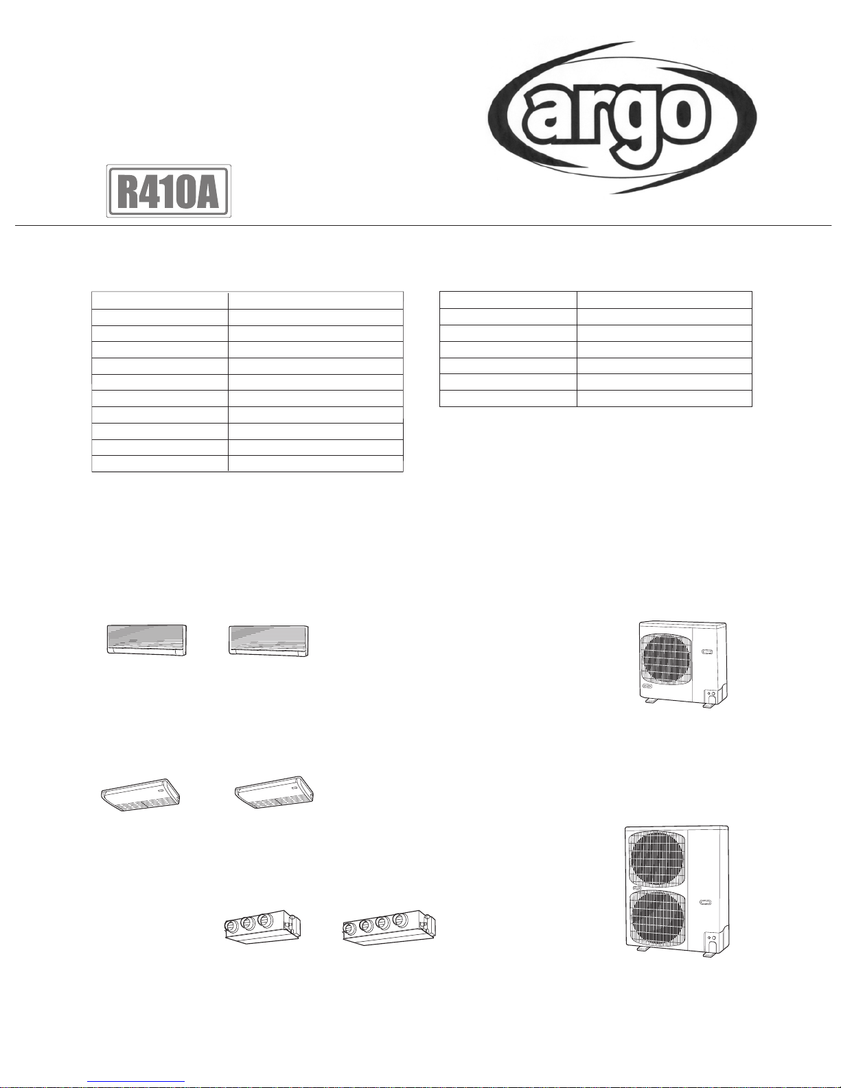
SPLIT SYSTEM AIR CONDITIONER
INDOOR MODEL NO. PRODUCT CODE NO.
OUTDOOR MODE L NO. P R ODUCT C ODE NO.
Indoor Unit
Outdoor Unit
TECHNICAL DATA
&
SERVICE MANUAL
AWS36PH 387030090
AWS45PH 387030091
AWS56PH 387030092
AWS71PH 387030093
ACS71PH 387030081
ACS100PH 387030082
ACS125PH 387030083
ADS71PH 387030087
ADS100PH 387030088
ADS125PH 387030089
AWS36PH AWS71PH
AWS45PH
AWS56PH
AES71PIC 387031037
AES71PIH 387031040
AES100PIC 387031038
AES100PIH 387031041
AES125PIC 387031039
AES125PIH 387031042
ACS71PH ACS100PH
ACS125PH
ADS71PH
ADS100PH
ADS125PH
AES71PIC
AES71PIH
AES100PIC
AES100PIH
AES125PIC
AES125PIH
Page 2

CONTENTS
Section 1: SPECIFICATIONS . . . . . . . . . . . . . . . . . . . . . . . . . . . . . . . . . . . . . . . . . . . . 1 - 1
1-1. Unit Specifications . . . . . . . . . . . . . . . . . . . . . . . . . . . . . . . . . . . . . . . . . . . . . . . . . . . . 1 - 2
1-2. Major Component Specifications . . . . . . . . . . . . . . . . . . . . . . . . . . . . . . . . . . . . . . . . . 1 - 30
1-3. Other Component Specifications . . . . . . . . . . . . . . . . . . . . . . . . . . . . . . . . . . . . . . . . . 1 - 45
1-4. Dimensional Data . . . . . . . . . . . . . . . . . . . . . . . . . . . . . . . . . . . . . . . . . . . . . . . . . . . . 1 - 54
1-5. Refrigerant Flow Diagram . . . . . . . . . . . . . . . . . . . . . . . . . . . . . . . . . . . . . . . . . . . . . . 1 - 61
1-6. Operating Range . . . . . . . . . . . . . . . . . . . . . . . . . . . . . . . . . . . . . . . . . . . . . . . . . . . . . 1 - 62
1-7. Capacity Correction Graph According to Temperature Condition . . . . . . . . . . . . . . . . 1 - 63
1-8. Noise Criterion Curves . . . . . . . . . . . . . . . . . . . . . . . . . . . . . . . . . . . . . . . . . . . . . . . . 1 - 64
1-9. Indoor Fan Performance . . . . . . . . . . . . . . . . . . . . . . . . . . . . . . . . . . . . . . . . . . . . . . . 1 - 68
1-10. Air Throw Distance Chart . . . . . . . . . . . . . . . . . . . . . . . . . . . . . . . . . . . . . . . . . . . . . . 1 - 69
1-11. Installation Iinstructions . . . . . . . . . . . . . . . . . . . . . . . . . . . . . . . . . . . . . . . . . . . . . . . . 1 - 71
Section 2: PROCESS AND FUNCTIONS . . . . . . . . . . . . . . . . . . . . . . . . . . . . . . . . . . . 2 - 1
2-1. Control Functions . . . . . . . . . . . . . . . . . . . . . . . . . . . . . . . . . . . . . . . . . . . . . . . . . . . . 2 - 2
2-2. Outdoor Unit Control PCB . . . . . . . . . . . . . . . . . . . . . . . . . . . . . . . . . . . . . . . . . . . . . 2 - 5
2-3. Indoor Unit Control PCB Switches and Functions . . . . . . . . . . . . . . . . . . . . . . . . . . . . 2 - 9
Section 3. ELECTRICAL DATA . . . . . . . . . . . . . . . . . . . . . . . . . . . . . . . . . . . . . . . . . . 3 - 1
3-1. Indoor Units (Electric Wiring Diagram, Schematic Diagram) . . . . . . . . . . . . . . . . . . . . 3 - 2
3-2. Outdoor Units (Electric Wiring Diagram, Schematic Diagram) . . . . . . . . . . . . . . . . . . 3 - 6
Section 4. SERVICE PROCEDURES . . . . . . . . . . . . . . . . . . . . . . . . . . . . . . . . . . . . . . 4 - 1
4-1. Meaning of Alarm Messages . . . . . . . . . . . . . . . . . . . . . . . . . . . . . . . . . . . . . . . . . . . . 4 - 2
4-2. LED Indicator Messages on Outdoor Control PCB . . . . . . . . . . . . . . . . . . . . . . . . . . . 4 - 4
4-3. Symptoms and Parts to Inspect . . . . . . . . . . . . . . . . . . . . . . . . . . . . . . . . . . . . . . . . . . 4 - 5
4-4. Details of Alarm Messages . . . . . . . . . . . . . . . . . . . . . . . . . . . . . . . . . . . . . . . . . . . . . 4 - 8
4-5. Table of Thermistor Characteristics . . . . . . . . . . . . . . . . . . . . . . . . . . . . . . . . . . . . . . . 4 - 14
Section 5. OUTDOOR UNIT MAINTENANCE REMOTE CONTROL
(ACC • CH80UI) . . . . . . . . . . . . . . . . . . . . . . . . . . . . . . . . . . . . . . . . . . . . . . 5 - 1
5-1. Overview . . . . . . . . . . . . . . . . . . . . . . . . . . . . . . . . . . . . . . . . . . . . . . . . . . . . . . . . . . . 5 - 2
5-2. Functions . . . . . . . . . . . . . . . . . . . . . . . . . . . . . . . . . . . . . . . . . . . . . . . . . . . . . . . . . . . 5 - 2
5-3. Normal Display Operations and Functions . . . . . . . . . . . . . . . . . . . . . . . . . . . . . . . . . 5 - 3
5-4. Monitoring Operations: Display of Indoor Unit and Outdoor Unit Sensor
Temperatures . . . . . . . . . . . . . . . . . . . . . . . . . . . . . . . . . . . . . . . . . . . . . . . . . . . . . . . . 5 - 6
5-5. Monitoring the Outdoor Unit Alarm History: Display of Outdoor Unit Alarm
History . . . . . . . . . . . . . . . . . . . . . . . . . . . . . . . . . . . . . . . . . . . . . . . . . . . . . . . . . . . . . 5 - 7
5-6. Settings Modes: Setting of Outdoor Unit EEPROM . . . . . . . . . . . . . . . . . . . . . . . . . . . 5 - 7
Page 3
1
1 - 1
1. SPECIFICATIONS
1-1. Unit Specifications . . . . . . . . . . . . . . . . . . . . . . . . . . . . . . . . . . . . . . . . . . . . . . . . . . 1 - 2
Wall-Mounted Type . . . . . . . . . . . . . . . . . . . . . . . . . . . . . . . . . . . . . . . . . . . . . . . . . . . . . . . . . . . . . . . . 1 - 2
Ceiling-Mounted Type . . . . . . . . . . . . . . . . . . . . . . . . . . . . . . . . . . . . . . . . . . . . . . . . . . . . . . . . . . . . . . . . 1 - 14
Concealed-Duct Type . . . . . . . . . . . . . . . . . . . . . . . . . . . . . . . . . . . . . . . . . . . . . . . . . . . . . . . . . . . . . . 1 - 22
1-2. Major Component Specifications . . . . . . . . . . . . . . . . . . . . . . . . . . . . . . . . . . . . . . 1 - 30
(A) Indoor Units . . . . . . . . . . . . . . . . . . . . . . . . . . . . . . . . . . . . . . . . . . . . . . . . . . . . . . . . . . . . . . . . . . . 1 - 30
(B) Outdoor Units . . . . . . . . . . . . . . . . . . . . . . . . . . . . . . . . . . . . . . . . . . . . . . . . . . . . . . . . . . . . . . . . . . 1 - 39
1-3. Other Component Specifications . . . . . . . . . . . . . . . . . . . . . . . . . . . . . . . . . . . . . . 1 - 45
Wall-Mounted Type . . . . . . . . . . . . . . . . . . . . . . . . . . . . . . . . . . . . . . . . . . . . . . . . . . . . . . . . . . . . . . . . 1 - 45
Ceiling-Mounted Type . . . . . . . . . . . . . . . . . . . . . . . . . . . . . . . . . . . . . . . . . . . . . . . . . . . . . . . . . . . . . . . . 1 - 46
Concealed-Duct Type . . . . . . . . . . . . . . . . . . . . . . . . . . . . . . . . . . . . . . . . . . . . . . . . . . . . . . . . . . . . . . 1 - 47
Outdoor Units . . . . . . . . . . . . . . . . . . . . . . . . . . . . . . . . . . . . . . . . . . . . . . . . . . . . . . . . . . . . . . . . . . . . . 1 - 48
1-4. Dimensional Data . . . . . . . . . . . . . . . . . . . . . . . . . . . . . . . . . . . . . . . . . . . . . . . . . . .
1 - 54
(A) Indoor Units . . . . . . . . . . . . . . . . . . . . . . . . . . . . . . . . . . . . . . . . . . . . . . . . . . . . . . . . . . . . . . . . . . . 1 - 54
Wall-Mounted Type . . . . . . . . . . . . . . . . . . . . . . . . . . . . . . . . . . . . . . . . . . . . . . . . . . . . . . . . . . . . . 1 - 54
Ceiling-Mounted Type . . . . . . . . . . . . . . . . . . . . . . . . . . . . . . . . . . . . . . . . . . . . . . . . . . . . . . . . . . . . . 1 - 55
Concealed-Duct Type . . . . . . . . . . . . . . . . . . . . . . . . . . . . . . . . . . . . . . . . . . . . . . . . . . . . . . . . . . . 1 - 56
Flange for Air Intake Duct . . . . . . . . . . . . . . . . . . . . . . . . . . . . . . . . . . . . . . . . . . . . . . . . . . . . . . . . . 1 - 58
(B) Outdoor Units . . . . . . . . . . . . . . . . . . . . . . . . . . . . . . . . . . . . . . . . . . . . . . . . . . . . . . . . . . . . . . . . . . 1 - 59
1-5. Refrigerant Flow Diagram . . . . . . . . . . . . . . . . . . . . . . . . . . . . . . . . . . . . . . . . . . . . 1 - 61
1-6. Operating Range . . . . . . . . . . . . . . . . . . . . . . . . . . . . . . . . . . . . . . . . . . . . . . . . . . . . 1 - 62
1-7. Capacity Correction Graph According to Temperature Condition . . . . . . . . . . . . 1 - 63
1-8. Noise Criterion Curves . . . . . . . . . . . . . . . . . . . . . . . . . . . . . . . . . . . . . . . . . . . . . . .
1 - 64
1-9. Indoor Fan Performance . . . . . . . . . . . . . . . . . . . . . . . . . . . . . . . . . . . . . . . . . . . . . .
1 - 68
1-10. Air Throw Distance Chart . . . . . . . . . . . . . . . . . . . . . . . . . . . . . . . . . . . . . . . . . . . . .
1 - 69
1-11. Installation Iinstructions . . . . . . . . . . . . . . . . . . . . . . . . . . . . . . . . . . . . . . . . . . . . . . 1 - 71
Tubing Size . . . . . . . . . . . . . . . . . . . . . . . . . . . . . . . . . . . . . . . . . . . . . . . . . . . . . . . . . . . . . . . . . . . . . . 1 - 71
Selecting the Installation Site . . . . . . . . . . . . . . . . . . . . . . . . . . . . . . . . . . . . . . . . . . . . . . . . . . . . . . . . 1 - 75
Electrical Wiring . . . . . . . . . . . . . . . . . . . . . . . . . . . . . . . . . . . . . . . . . . . . . . . . . . . . . . . . . . . . . . . . . . . 1 - 77
Page 4
1
1 - 2
)
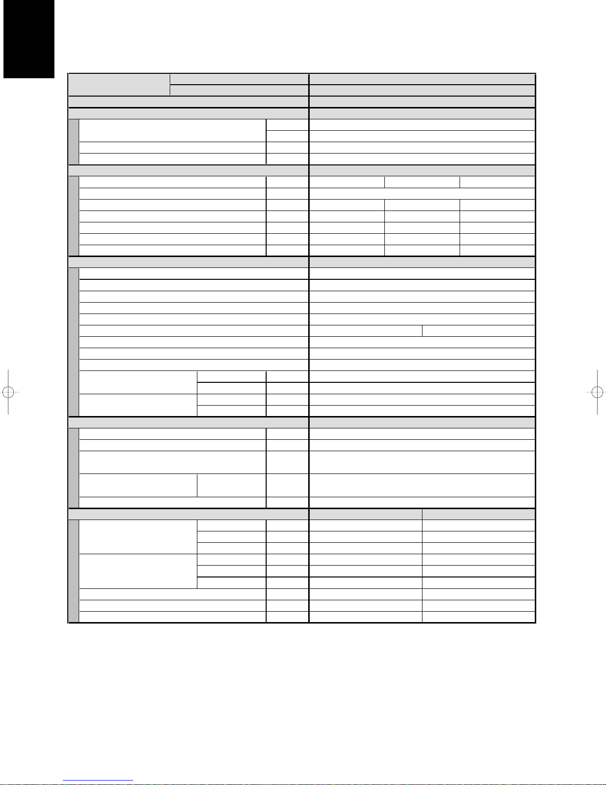
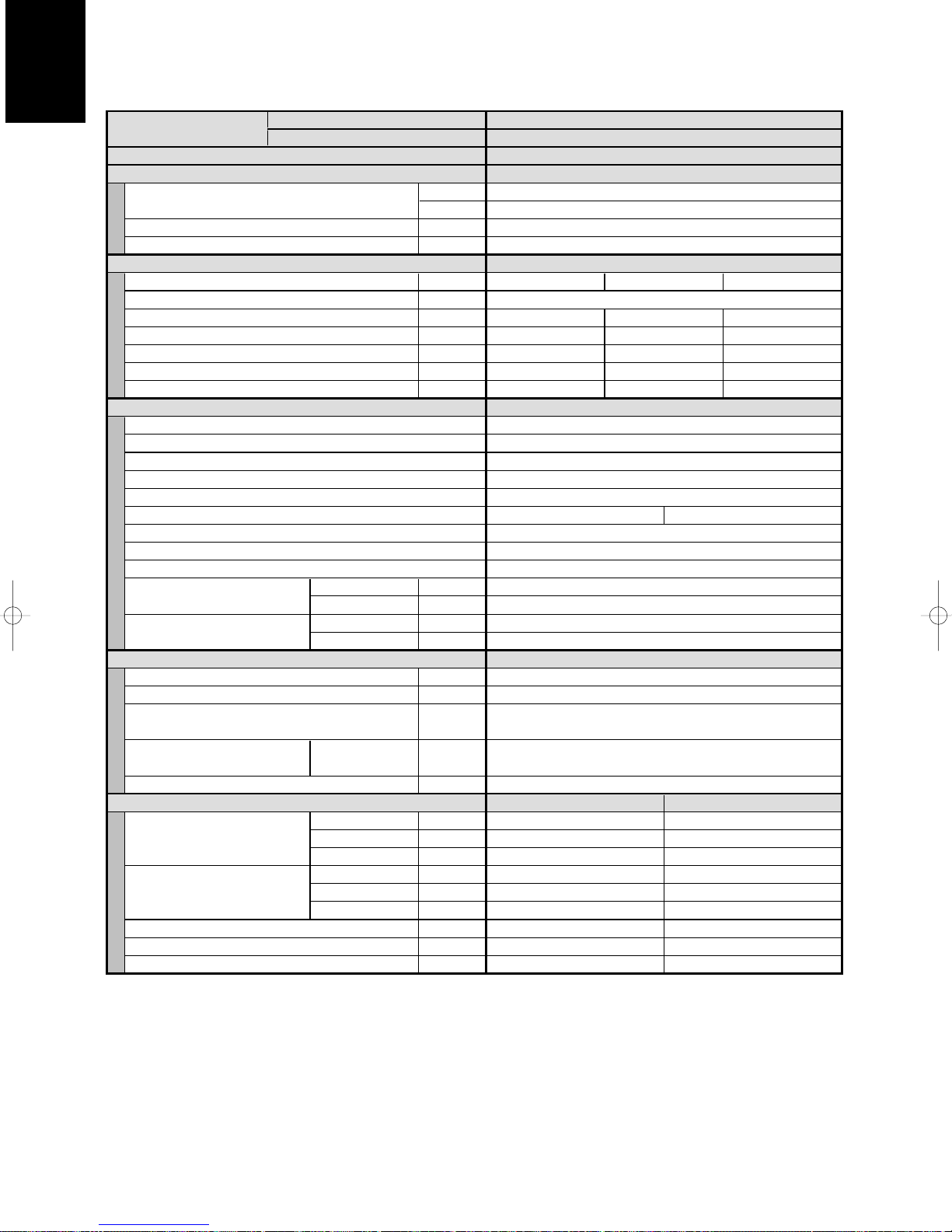
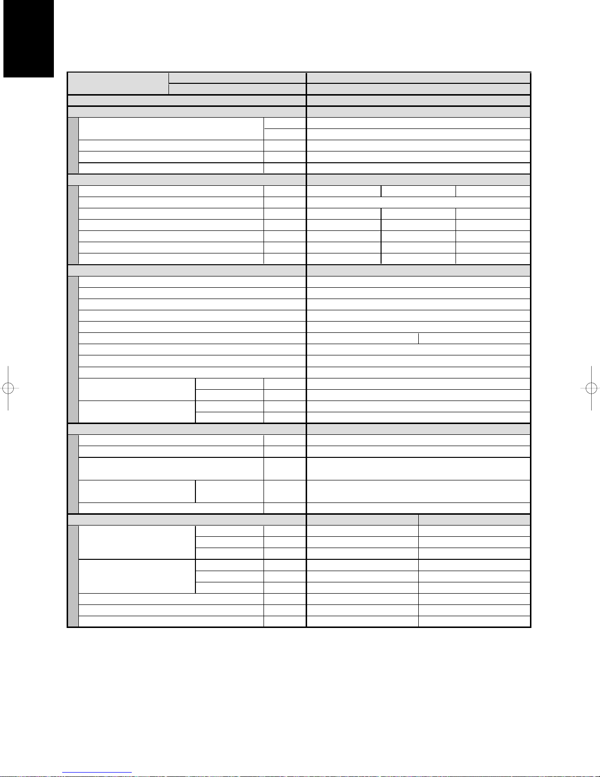
1-1. Unit Specifications
Wall-Mounted Type AWS36PH
××
2 / AES71PIC
MODEL No. Indoor Unit AWS36PH x 2
POWER SOURCE
PERFORMANCE Cooling
Capacity [minimum~maximum] kW
Air circulation (Hi/Me/Lo) m3/h
Moisture removal (High) Liters/h
ELECTRICAL RATINGS
Voltage rating V
Available voltage range V
Running amperes* A
Max–Running amperes** A
Power input kW
C.O.P W/W
Max. Starting amperes A
FEATURES
Controls/Thermostat control
Timer
Fan speeds Indoor/Outdoor
Airflow direction (Indoor)
Air filter
Remote controller (Option)
Refrigerant control
Drain pump (Drain connection)
Compressor
Operation sound Indoor - Hi/Me/Lo dB - A
Color (Approximate value) Indoor
REFRIGERANT TUBING
Limit of tubing length m (ft.)
Limit of tubing length at shipment m (ft.)
Limit of elevation difference m (ft.)
between the two units
Refrigerant tube Narrow tube mm (in.)
outer diameter Wide tube mm (in.)
Refrigerant amount at shipment kg
DIMENSIONS & WEIGHT
Unit dimensions Height mm (in.)
Package dimensions Height mm (in.)
Net weight kg (lb.)
Shipping weight kg (lb.)
Shipping volume
Cooling:
Rating conditions (*): Indoor air temperature 27°C DB/19°C WB, Outdoor air temperature 35°C DB
Full load conditions (**): Indoor air temperature 32°C DB/23°C WB, Outdoor air temperature 43°C DB
Outdoor Unit AES71PIC
220 - 230 - 240 V/1 phase/50/60 Hz
BTU/h
Outdoor - Hi dB - A
Outdoor
Width mm (in.)
Depth mm (in.)
Width mm (in.)
Depth mm (in.)
3
m
(cu. Ft
220 230
13.3 12.8
3.00 2.98 2.98
Wired : REM HW Wireless : REM HLAWS
Outdoor unit is higher than indoor unit : 30 (98)
Outdoor unit is lower than indoor unit : 15 (49)
Indoor unit Outdoor unit
285 (11-7/32)
995 (39-6/32) 940 (37)
203 (8) 340 (13- 3 /8)
347 (13-21/32) 888 (34-31/32)
1,065 (41-30/32)
260 (10-8/32) 409 (16-3/ 32)
12 (27) 58 (128)
15 (33) 67 (148)
0.096 (3.4) 0.369 (13.0)
24,000 [7,500~27,000]
1,440/1,200/840 (720/600/420x2)
Microprocessor/I.C.thermostat
ON/OFF 72-hours
3 and Automatic control/Variable
Automatic (Remote control)
Washable, easy access
(13A , OD18mm)
Munsell 3.0Y8.6/0.8
Munsell 1Y 8.5/0.5
DATA SUBJECT TO CHANGE WITHOUT NOTICE.
7.1 [2.2~8.0]
Rotary(SANYO)
3~30 (10~98)
R410A - 1.9
3.8 (1.9x2)
240
198 - 264
12.3
2.38 2.382.37
–
35/31/27
47
50 (164)
6.35 (1/4)
12.7 (1/2)
780 (30-23/32)
1015 (39-31/32)
Page 5

1
1 - 3
)
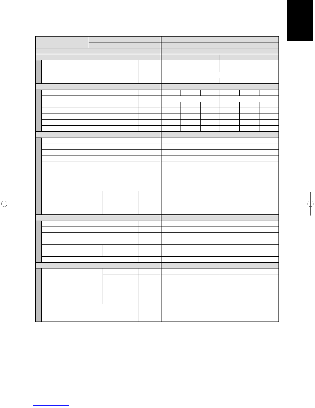
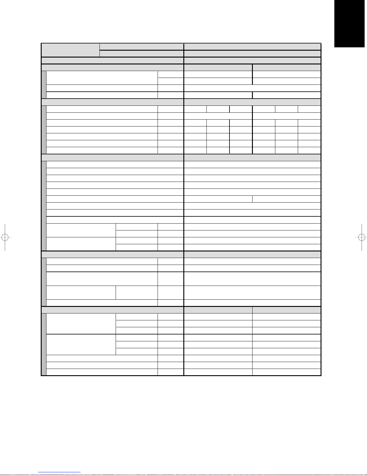
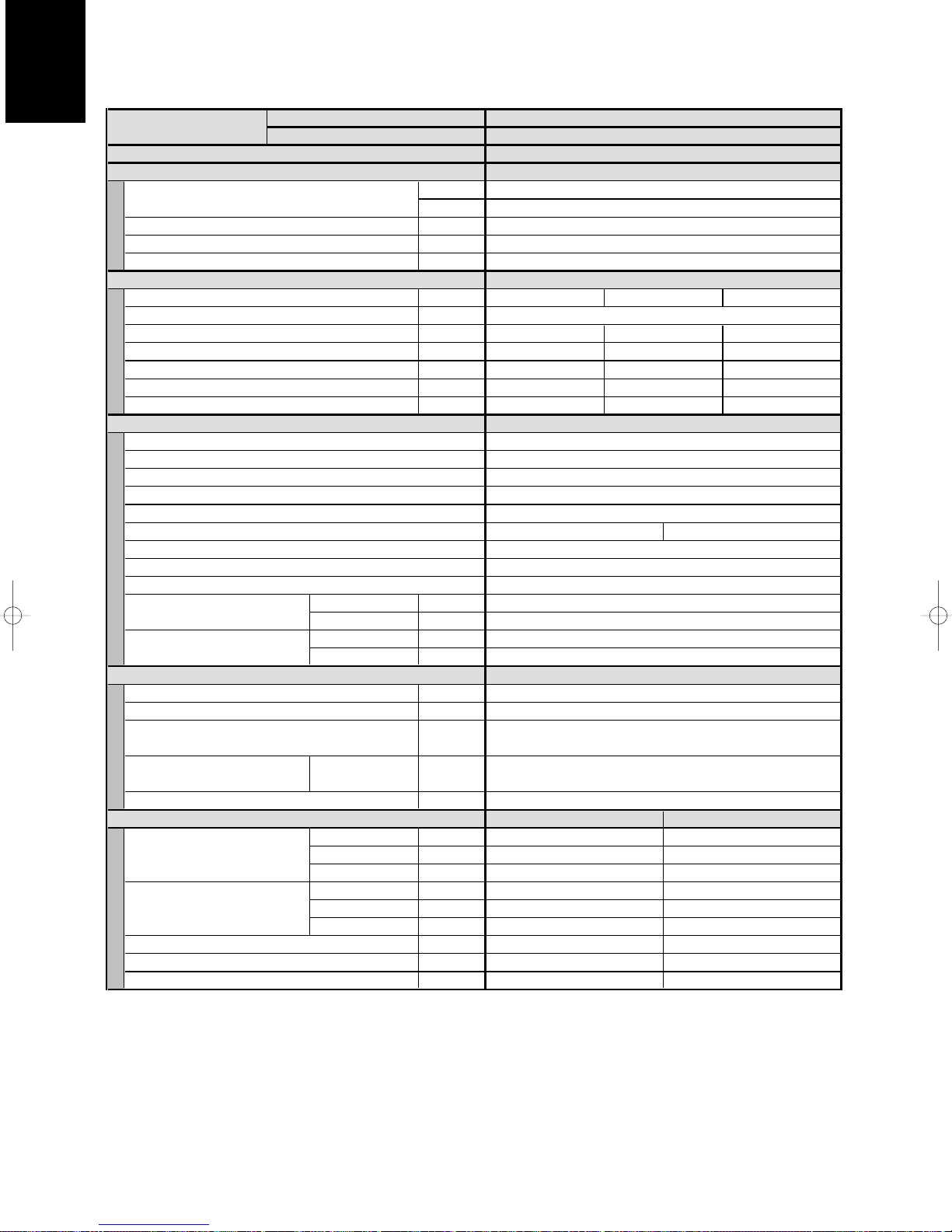
1-1. Unit Specifications
Wall-Mounted Type AWS36PH
××
2 / AES71PIH
MODEL No. Indoor Unit
POWER SOURCE
PERFORMANCE
Capacity [minimum~maximum] kW
Air circulation (Hi/Me/Lo) m3/h
Moisture removal (High) Liters/h
ELECTRICAL RATINGS
Voltage rating V
Available voltage range V
Running amperes* A
Max–Running amperes** A
Power input kW
C.O.P W/W
Max. Starting amperes A
FEATURES
Controls/Thermostat control
Timer
Fan speeds Indoor/Outdoor
Airflow direction (Indoor)
Air filter
Remote controller (Option)
Refrigerant control
Drain pump (Drain connection)
Compressor
Operation sound Indoor - Hi/Me/Lo dB - A
Color (Approximate value) Indoor
REFRIGERANT TUBING
Limit of tubing length m (ft.)
Limit of tubing length at shipment m (ft.)
Limit of elevation difference m (ft.)
between the two units
Refrigerant tube Narrow tube mm (in.)
outer diameter Wide tube mm (in.)
Refrigerant amount at shipment kg
DIMENSIONS & WEIGHT
Unit dimensions Height mm (in.)
Package dimensions Height mm (in.)
Net weight kg (lb.)
Shipping weight kg (lb.)
Shipping volume
Cooling:
Rating conditions (*): Indoor air temperature 27°C DB/19°C WB, Outdoor air temperature 35°C DB
Full load conditions (**): Indoor air temperature 32°C DB/23°C WB, Outdoor air temperature 43°C DB
Heating:
Rating conditions (*): Indoor air temperature 20°C DB, Outdoor air temperature 7°C DB/6°C WB
Full load conditions (**): Indoor air temperature 24°C DB, Outdoor air temperature 24°C DB/15.5°C WB
Outdoor Unit
BTU/h
Outdoor - Hi dB - A
Outdoor
Width mm (in.)
Depth mm (in.)
Width mm (in.)
Depth mm (in.)
3
m
(cu. Ft
220 - 230 - 240 V/1 phase/50/60 Hz
Cooling Heating
7.1 [2.2~8.0] 8.0 [2.2~9.0]
1,440/1,200/840 (720/600/420x2)
3.8 (1.9x2) –
198 - 264 198 - 264
13.3 12.8 12.3 12.8 12.3 11.8
2.37 2.38 2.38 2.27 2.28 2.28
3.00
Wired : REM HW Wireless : REM HLAWS
2.98 3.51
3 and Automatic control/Variable
Outdoor unit is higher than indoor unit : 30 (98)
Outdoor unit is lower than indoor unit : 15 (49)
Indoor unit Outdoor unit
285 (11-7/32)
995 (39-6/32) 940 (37)
203 (8) 340 (13- 3 /8)
347 (13-21/32) 888 (34-31/32)
1,065 (41-30/32) 1015 (39-31/32)
260 (10-8/32) 409 (16-3/ 32)
12 (27) 58 (128)
15 (33) 67 (148)
0.096 (3.4) 0.369 (13.0)
DATA SUBJECT TO CHANGE WITHOUT NOTICE.
AWS36PH x 2
AES71PIH
27,000 [7,500~30,000]24,000 [7,500~27,000]
240 220 230 240220 230
2.98 3.52
Microprocessor/I.C.thermostat
ON/OFF 72-hours
Automatic (Remote control)
Washable, easy access
–
(13A , OD18mm)
Rotary(SANYO)
35/31/27
47/49
Munsell 3.0Y8.6/0.8
Munsell 1Y 8.5/0.5
50 (164)
3~30 (10~98)
6.35 (1/4)
12.7 (1/2)
R410A - 1.9
780 (30-23/32)
3.51
Page 6

1
1 - 4
)
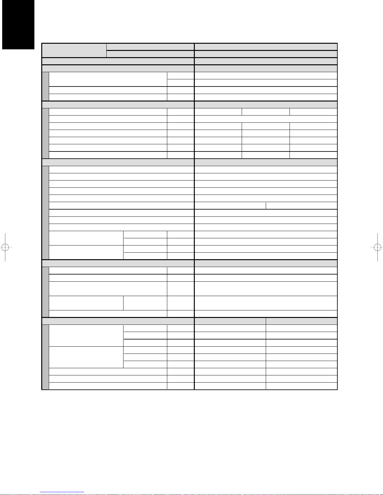
1-1. Unit Specifications
Wall-Mounted Type AWS36PH
××
4 / AES125PIC
MODEL No. Indoor Unit AWS36PHx4
POWER SOURCE 220 - 230 - 240 V/1 phase/50/60 Hz
PERFORMANCE Cooling
Capacity [minimum~maximum] kW
Air circulation (Hi/Me/Lo) m3/h
Moisture removal (High) Liters/h
ELECTRICAL RATINGS
Voltage rating V
Available voltage range V
Running amperes* A
Max–Running amperes** A
Power input kW
C.O.P W/W
Max. Starting amperes A
FEATURES
Controls/Thermostat control
Timer
Fan speeds Indoor/Outdoor
Airflow direction (Indoor)
Air filter
Remote controller (Option)
Refrigerant control
Drain pump (Drain connection)
Compressor
Operation sound Indoor - Hi/Me/Lo dB - A
Color (Approximate value) Indoor
REFRIGERANT TUBING
Limit of tubing length m (ft.)
Limit of tubing length at shipment m (ft.)
Limit of elevation difference m (ft.)
between the two units
Refrigerant tube Narrow tube mm (in.)
outer diameter Wide tube mm (in.)
Refrigerant amount at shipment kg
DIMENSIONS & WEIGHT
Unit dimensions Height mm (in.)
Package dimensions Height mm (in.)
Net weight kg (lb.)
Shipping weight kg (lb.)
Shipping volume
Cooling:
Rating conditions (*): Indoor air temperature 27°C DB/19°C WB, Outdoor air temperature 35°C DB
Full load conditions (**): Indoor air temperature 32°C DB/23°C WB, Outdoor air temperature 43°C DB
Outdoor Unit AES125PIC
BTU/h
Outdoor - Hi dB - A
Outdoor
Width mm (in.)
Depth mm (in.)
Width mm (in.)
Depth mm (in.)
3
m
(cu. Ft
220 230 240
21.2 20.3 19.5
4.15
3.01
Wired : REM HW Wireless : REM HLAWS
Outdoor unit is higher than indoor unit : 30 (98)
Outdoor unit is lower than indoor unit : 15 (49)
Indoor unit Outdoor unit
285 (11-7/32) 1230 (48- 7/16)
995 (39-6/32) 940 (37)
203 (8) 340 (13-3 /8)
347 (13-21/32) 1330 (52-3 /8)
1,065 (41-30/32) 1015 (39-31/32)
260 (10-8/32) 409 (16-3/32)
12 (27) 100 (220)
15 (33) 109 (240)
0.096 (3.4) 0.552 (19.5)
42,500 [9,200~48,000]
2,880/2,400/1,680 (720/600/420x4)
Microprocessor/I.C.thermostat
3 and Automatic control/Variable
Automatic (Remote control)
Washable, easy access
Munsell 3.0Y8.6/0.8
DATA SUBJECT TO CHANGE WITHOUT NOTICE.
12.5 [2.7~14.0]
7.6 (1.9x4)
198 - 264
4.16 4.17
3.00 3.00
ON/OFF 72-hours
–
(13A , OD18mm)
Rotary(SANYO)
35/31/27
52
Munsell 1Y 8.5/0.5
50 (164)
5~30 (16~98)
6.35 (1/4)
12.7 (1/2)
R410A - 3.6
Page 7

1
1 - 5
)
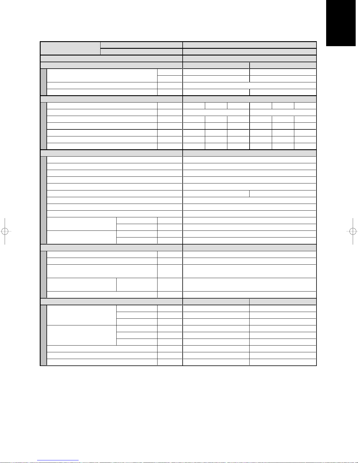
1-1. Unit Specifications
Wall-Mounted Type AWS36PH
××
4 / AES125PIH
MODEL No. Indoor Unit AWS36PH x 4
POWER SOURCE
PERFORMANCE Cooling Heating
Capacity [minimum~maximum] kW
Air circulation (Hi/Me/Lo) m3/h
Moisture removal (High) Liters/h
ELECTRICAL RATINGS
Voltage rating V
Available voltage range V
Running amperes* A
Max–Running amperes** A
Power input kW
C.O.P W/W
Max. Starting amperes A
FEATURES
Controls/Thermostat control
Timer
Fan speeds Indoor/Outdoor
Airflow direction (Indoor)
Air filter
Remote controller (Option)
Refrigerant control
Drain pump (Drain connection)
Compressor
Operation sound Indoor - Hi/Me/Lo dB - A
Color (Approximate value) Indoor
REFRIGERANT TUBING
Limit of tubing length m (ft.)
Limit of tubing length at shipment m (ft.)
Limit of elevation difference m (ft.)
between the two units
Refrigerant tube Narrow tube mm (in.)
outer diameter Wide tube mm (in.)
Refrigerant amount at shipment kg
DIMENSIONS & WEIGHT
Unit dimensions Height mm (in.)
Package dimensions Height mm (in.)
Net weight kg (lb.)
Shipping weight kg (lb.)
Shipping volume
Cooling:
Rating conditions (*): Indoor air temperature 27°C DB/19°C WB, Outdoor air temperature 35°C DB
Full load conditions (**): Indoor air temperature 32°C DB/23°C WB, Outdoor air temperature 43°C DB
Heating:
Rating conditions (*): Indoor air temperature 20°C DB, Outdoor air temperature 7°C DB/6°C WB
Full load conditions (**): Indoor air temperature 24°C DB, Outdoor air temperature 24°C DB/15.5°C WB
Outdoor Unit AES125PIH
220 - 230 - 240 V/1 phase/50/60 Hz
12.5 [2.7~14.0] 14.0 [2.7~16.0]
BTU/h
Outdoor - Hi dB - A
Outdoor
Width mm (in.)
Depth mm (in.)
Width mm (in.)
Depth mm (in.)
3
m
(cu. Ft
42,500 [9,200~48,000] 48,000 [9,200~54,500]
2,880/2,400/1,680 (720/600/420x4)
7.6 (1.9x4)
220 230 240 220 230 240
198 - 264 198 - 264
21.2
4.15
3.01
Wired : REM HW Wireless : REM HLAWS
20.3
4.16
3.00
Microprocessor/I.C.thermostat
ON/OFF 72-hours
3 and Automatic control/Variable
Automatic (Remote control)
Washable, easy access
(13A , OD18mm)
Rotary(SANYO)
Munsell 3.0Y8.6/0.8
Munsell 1Y 8.5/0.5
Outdoor unit is higher than indoor unit : 30 (98)
Outdoor unit is lower than indoor unit : 15 (49)
Indoor unit Outdoor unit
285 (11-7/32) 1230 (48- 7/16)
995 (39-6/32) 940 (37)
203 (8) 340 (13-3 /8)
347 (13-21/32) 1330 (52-3 /8)
1,065 (41-30/32) 1015 (39-31/32)
260 (10-8/32) 409 (16-3/32)
12 (27) 100 (220)
15 (33) 109 (240)
0.096 (3.4) 0.552 (19.5)
DATA SUBJECT TO CHANGE WITHOUT NOTICE.
19.5 21.0 20.0 19.2
4.17 4.11
3.00 3.41
–
35/31/27
52/53
50 (164)
5~30 (16~98)
6.35 (1/4)
12.7 (1/2)
R410A - 3.6
–
4.11 4.12
3.41 3.40
Page 8

1
1 - 6
)
1-1. Unit Specifications
Wall-Mounted Type AWS45PH
××
3 / AES125PIC
MODEL No. Indoor Unit
POWER SOURCE 220 - 230 - 240 V/1 phase/50/60 Hz
PERFORMANCE Cooling
Capacity [minimum~maximum] kW
Air circulation (Hi/Me/Lo) m3/h
Moisture removal (High) Liters/h
ELECTRICAL RATINGS
Voltage rating V
Available voltage range V
Running amperes* A
Max–Running amperes** A
Power input kW
C.O.P W/W
Max. Starting amperes A
FEATURES
Controls/Thermostat control
Timer
Fan speeds Indoor/Outdoor
Airflow direction (Indoor)
Air filter
Remote controller (Option)
Refrigerant control
Drain pump (Drain connection)
Compressor
Operation sound Indoor - Hi/Me/Lo dB - A
Color (Approximate value) Indoor
REFRIGERANT TUBING
Limit of tubing length m (ft.)
Limit of tubing length at shipment m (ft.)
Limit of elevation difference m (ft.)
between the two units
Refrigerant tube Narrow tube mm (in.)
outer diameter Wide tube mm (in.)
Refrigerant amount at shipment kg
DIMENSIONS & WEIGHT
Unit dimensions Height mm (in.)
Package dimensions Height mm (in.)
Net weight kg (lb.)
Shipping weight kg (lb.)
Shipping volume
Cooling:
Rating conditions (*): Indoor air temperature 27°C DB/19°C WB, Outdoor air temperature 35°C DB
Full load conditions (**): Indoor air temperature 32°C DB/23°C WB, Outdoor air temperature 43°C DB
Outdoor Unit AES125PIC
BTU/h
Outdoor - Hi dB - A
Outdoor
Width mm (in.)
Depth mm (in.)
Width mm (in.)
Depth mm (in.)
3
m
(cu. Ft
220 230 240
21.0
4.12
3.03
Wired : REM HW Wireless : REM HLAWS
Outdoor unit is higher than indoor unit : 30 (98)
Outdoor unit is lower than indoor unit : 15 (49)
Indoor unit Outdoor unit
285 (11-7/32) 1230 (48- 7/16)
995 (39-6/32) 940 (37)
203 (8) 340 (13-3 /8)
347 (13-21/32) 1330 (52-3 /8)
1,065 (41-30/32) 1015 (39-31/32)
260 (10-8/32) 409 (16-3/32)
12 (27) 100 (220)
15 (33) 109 (240)
0.096 (3.4) 0.552 (19.5)
42,500 [9,200~48,000]
2,160/1,800/1,260 (720/600/420x3)
Microprocessor/I.C.thermostat
ON/OFF 72-hours
3 and Automatic control/Variable
Automatic (Remote control)
Washable, easy access
(13A , OD18mm)
Munsell 3.0Y8.6/0.8
Munsell 1Y 8.5/0.5
DATA SUBJECT TO CHANGE WITHOUT NOTICE.
AWS45PH x 3
12.5 [2.7~14.0]
5.7 (1.9x3)
198 - 264
20.1 19.4
4.13 4.14
3.03 3.02
–
Rotary(SANYO)
35/31/27
52
50 (164)
5~30 (16~98)
6.35 (1/4)
12.7 (1/2)
R410A - 3.6
Page 9
1
1 - 7
)
1-1. Unit Specifications
Wall-Mounted Type AWS45PH
××
3 / AES125PIH
MODEL No. Indoor Unit AWS45PH x 3
POWER SOURCE 220 - 230 - 240 V/1 phase/50/60 Hz
PERFORMANCE Cooling Heating
Capacity [minimum~maximum] kW
Air circulation (Hi/Me/Lo) m3/h
Moisture removal (High) Liters/h
ELECTRICAL RATINGS
Voltage rating V
Available voltage range V
Running amperes* A
Max–Running amperes** A
Power input kW
C.O.P W/W
Max. Starting amperes A
FEATURES
Controls/Thermostat control
Timer
Fan speeds Indoor/Outdoor
Airflow direction (Indoor)
Air filter
Remote controller (Option)
Refrigerant control
Drain pump (Drain connection)
Compressor
Operation sound Indoor - Hi/Me/Lo dB - A
Color (Approximate value) Indoor
REFRIGERANT TUBING
Limit of tubing length m (ft.)
Limit of tubing length at shipment m (ft.)
Limit of elevation difference m (ft.)
between the two units
Refrigerant tube Narrow tube mm (in.)
outer diameter Wide tube mm (in.)
Refrigerant amount at shipment kg
DIMENSIONS & WEIGHT
Unit dimensions Height mm (in.)
Package dimensions Height mm (in.)
Net weight kg (lb.)
Shipping weight kg (lb.)
Shipping volume
Cooling:
Rating conditions (*): Indoor air temperature 27°C DB/19°C WB, Outdoor air temperature 35°C DB
Full load conditions (**): Indoor air temperature 32°C DB/23°C WB, Outdoor air temperature 43°C DB
Heating:
Rating conditions (*): Indoor air temperature 20°C DB, Outdoor air temperature 7°C DB/6°C WB
Full load conditions (**): Indoor air temperature 24°C DB, Outdoor air temperature 24°C DB/15.5°C WB
Outdoor Unit AES125PIH
12.5 [2.7~14.0] 14.0 [2.7~16.0]
BTU/h
Outdoor - Hi dB - A
Outdoor
Width mm (in.)
Depth mm (in.)
Width mm (in.)
Depth mm (in.)
3
(cu. Ft
m
42,500 [9,200~48,000] 48,000 [9,200~54,500]
2,160/1,800/1,260 (720/600/420x3)
5.7 (1.9x3) –
220 230 240 220
198 - 264 198 - 264
21.0 20.1 19.4 20.8 19.8 19.1
4.12
Microprocessor/I.C.thermostat
ON/OFF 72-hours
3 and Automatic control/Variable
Automatic (Remote control)
Washable, easy access
Wired : REM HW
(13A , OD18mm)
Munsell 3.0Y8.6/0.8
Munsell 1Y 8.5/0.5
Outdoor unit is higher than indoor unit : 30 (98)
Outdoor unit is lower than indoor unit : 15 (49)
Indoor unit Outdoor unit
285 (11-7/32) 1230 (48- 7/16)
995 (39-6/32) 940 (37)
203 (8) 340 (13-3 /8)
347 (13-21/32) 1330 (52-3 /8)
1,065 (41-30/32) 1015 (39-31/32)
260 (10-8/32) 409 (16-3/32)
12 (27) 100 (220)
15 (33) 109 (240)
0.096 (3.4) 0.552 (19.5)
DATA SUBJECT TO CHANGE WITHOUT NOTICE.
3.02 3.43
Wireless : REM HLAWS
–
Rotary(SANYO)
35/31/27
52/53
50 (164)
5~30 (16~98)
6.35 (1/4)
12.7 (1/2)
R410A - 3.6
230 240
4.094.13 4.14 4.08 4.08
3.43 3.423.03 3.03
Page 10
1
1 - 8
)
1-1. Unit Specifications
Wall-Mounted Type AWS56PH
××
2 / AES100PIC
MODEL No. Indoor Unit AWS56PH x 2
POWER SOURCE 220 - 230 - 240 V/1 phase/50/60 Hz
PERFORMANCE Cooling
Capacity [minimum~maximum] kW
Air circulation (Hi/Me/Lo) m3/h
Moisture removal (High) Liters/h
ELECTRICAL RATINGS
Voltage rating V
Available voltage range V
Running amperes* A
Max–Running amperes** A
Power input kW
C.O.P W/W
Max. Starting amperes A
FEATURES
Controls/Thermostat control
Timer
Fan speeds Indoor/Outdoor
Airflow direction (Indoor)
Air filter
Remote controller (Option)
Refrigerant control
Drain pump (Drain connection)
Compressor
Operation sound Indoor - Hi/Me/Lo dB - A
Color (Approximate value) Indoor
REFRIGERANT TUBING
Limit of tubing length m (ft.)
Limit of tubing length at shipment m (ft.)
Limit of elevation difference m (ft.)
between the two units
Refrigerant tube Narrow tube mm (in.)
outer diameter Wide tube mm (in.)
Refrigerant amount at shipment kg
DIMENSIONS & WEIGHT
Unit dimensions Height mm (in.)
Package dimensions Height mm (in.)
Net weight kg (lb.)
Shipping weight kg (lb.)
Shipping volume
Cooling:
Rating conditions (*): Indoor air temperature 27°C DB/19°C WB, Outdoor air temperature 35°C DB
Full load conditions (**): Indoor air temperature 32°C DB/23°C WB, Outdoor air temperature 43°C DB
Outdoor Unit AES100PIC
BTU/h
Outdoor - Hi dB - A
Outdoor
Width mm (in.)
Depth mm (in.)
Width mm (in.)
Depth mm (in.)
3
(cu. Ft
m
220 230 240
16.8
3.283.293.29
3.05 3.04 3.04
Wired : REM HW Wireless : REM HLAWS
Outdoor unit is higher than indoor unit : 30 (98)
Outdoor unit is lower than indoor unit : 15 (49)
Indoor unit Outdoor unit
995 (39-6/32) 940 (37)
203 (8) 340 (13-3 /8)
347 (13-21/32) 888 (34-31/32)
1,065 (41-30/32) 1015 (39-31/32)
260 (10-8/32) 409 (16-3/32)
12 (27) 65 (143)
15 (33) 73 (161)
0.096 (3.4) 0.369 (13.0)
34,000 [7,500~38,000]
1,560/1,320/960 (780/660/480x2)
Microprocessor/I.C.thermostat
ON/OFF 72-hours
3 and Automatic control/Variable
Automatic (Remote control)
Washable, easy access
Munsell 3.0Y8.6/0.8
Munsell 1Y 8.5/0.5
DATA SUBJECT TO CHANGE WITHOUT NOTICE.
10.0 [2.2~11.2]
4.2 (2.1x2)
198 - 264
16.0 15.3
–
(13A , OD18mm)
Rotary(SANYO)
38/34/30
51
50 (164)
5~30 (16~98)
6.35 (1/4)
12.7 (1/2)
R410A - 2.8
780 (30-23/32) 285 (11-7/32)
Page 11

1
1 - 9
)
1-1. Unit Specifications
Wall-Mounted Type AWS56PH
××
2 / AES100PIH
MODEL No. Indoor Unit AWS56PH x 2
POWER SOURCE 220 - 230 - 240 V/1 phase/50/60 Hz
PERFORMANCE Cooling Heating
Capacity [minimum~maximum] kW
Air circulation (Hi/Me/Lo) m3/h
Moisture removal (High) Liters/h
ELECTRICAL RATINGS
Voltage rating V
Available voltage range V
Running amperes* A
Max–Running amperes** A
Power input kW
C.O.P W/W
Max. Starting amperes A
FEATURES
Controls/Thermostat control
Timer
Fan speeds Indoor/Outdoor
Airflow direction (Indoor)
Air filter
Remote controller (Option)
Refrigerant control
Drain pump (Drain connection)
Compressor
Operation sound Indoor - Hi/Me/Lo dB - A
Color (Approximate value) Indoor
REFRIGERANT TUBING
Limit of tubing length m (ft.)
Limit of tubing length at shipment m (ft.)
Limit of elevation difference m (ft.)
between the two units
Refrigerant tube Narrow tube mm (in.)
outer diameter Wide tube mm (in.)
Refrigerant amount at shipment kg
DIMENSIONS & WEIGHT
Unit dimensions Height mm (in.)
Package dimensions Height mm (in.)
Net weight kg (lb.)
Shipping weight kg (lb.)
Shipping volume
Cooling:
Rating conditions (*): Indoor air temperature 27°C DB/19°C WB, Outdoor air temperature 35°C DB
Full load conditions (**): Indoor air temperature 32°C DB/23°C WB, Outdoor air temperature 43°C DB
Heating:
Rating conditions (*): Indoor air temperature 20°C DB, Outdoor air temperature 7°C DB/6°C WB
Full load conditions (**): Indoor air temperature 24°C DB, Outdoor air temperature 24°C DB/15.5°C WB
Outdoor Unit AES100PIH
10.0 [2.2~11.2] 11.2 [2.2~12.5]
BTU/h
Outdoor - Hi dB - A
Outdoor
Width mm (in.)
Depth mm (in.)
Width mm (in.)
Depth mm (in.)
3
m
(cu. Ft
34,000 [7,500~38,000] 38,000 [7,500~42,500]
1,560/1,320/960 (780/660/480x2)
4.2 (2.1x2) –
220 230 240 220
198 - 264 198 - 264
16.8 16.0 15.3 15.6
Microprocessor/I.C.thermostat
ON/OFF 72-hours
3 and Automatic control/Variable
Automatic (Remote control)
Washable, easy access
Wired : REM HW Wireless : REM HLAWS
Munsell 3.0Y8.6/0.8
Munsell 1Y 8.5/0.5
Outdoor unit is higher than indoor unit : 30 (98)
Outdoor unit is lower than indoor unit : 15 (49)
Indoor unit Outdoor unit
285 (11-7/32) 780 (30-23/32)
995 (39-6/32) 940 (37)
203 (8) 340 (13-3 /8)
347 (13-21/32) 888 (34-31/32)
1,065 (41-30/32) 1015 (39-31/32)
260 (10-8/32) 409 (16-3/32)
12 (27) 65 (143)
15 (33) 73 (161)
0.096 (3.4) 0.369 (13.0)
DATA SUBJECT TO CHANGE WITHOUT NOTICE.
3.29 3.04 3.05
–
(13A , OD18mm)
Rotary(SANYO)
38/34/30
51/52
50 (164)
5~30 (16~98)
6.35 (1/4)
12.7 (1/2)
R410A - 2.8
230 240
14.9 14.3
3.053.283.29
3.67 3.673.05 3.04 3.04 3.68
Page 12

1
1 - 10
)
1-1. Unit Specifications
Wall-Mounted Type AWS71PH / AES71PIC
MODEL No.
POWER SOURCE
PERFORMANCE
Capacity [minimum~maximum] kW
Air circulation (Hi/Me/Lo) m3/h
Moisture removal (High) Liters/h
ELECTRICAL RATINGS
Voltage rating V
Available voltage range V
Running amperes* A
Max–Running amperes** A
Power input kW
C.O.P W/W
Max. Starting amperes A
FEATURES
Controls/Thermostat control
Timer
Fan speeds Indoor/Outdoor
Airflow direction (Indoor)
Air filter
Remote controller (Option)
Refrigerant control
Drain pump (Drain connection)
Compressor
Operation sound Indoor - Hi/Me/Lo dB - A
Color (Approximate value) Indoor
REFRIGERANT TUBING
Limit of tubing length m (ft.)
Limit of tubing length at shipment m (ft.)
Limit of elevation difference m (ft.)
between the two units
Refrigerant tube Narrow tube mm (in.)
outer diameter Wide tube mm (in.)
Refrigerant amount at shipment kg
DIMENSIONS & WEIGHT
Unit dimensions Height mm (in.)
Package dimensions Height mm (in.)
Net weight kg (lb.)
Shipping weight kg (lb.)
Shipping volume
Cooling:
Rating conditions (*): Indoor air temperature 27°C DB/19°C WB, Outdoor air temperature 35°C DB
Full load conditions (**): Indoor air temperature 32°C DB/23°C WB, Outdoor air temperature 43°C DB
Indoor Unit
Outdoor Unit
BTU/h
Outdoor - Hi dB - A
Outdoor
Width mm (in.)
Depth mm (in.)
Width mm (in.)
Depth mm (in.)
3
m
(cu. Ft
220 - 230 - 240 V/1 phase/50/60 Hz
220 240
13.2
2.36
3.01
Microprocessor/I.C.thermostat
3 and Automatic control/Variable
Automatic (Remote control)
Wired : REM HW Wireless : REM HLAWS
Outdoor unit is higher than indoor unit : 30 (98)
Outdoor unit is lower than indoor unit : 15 (49)
330 (13)
1,140 (44-28/32)
228 (8-31/32)
390 (15-11/32)
1,215 (47-27/32)
293 (11-17/32)
21 (46)
24 (53)
0.139 (4.9)
DATA SUBJECT TO CHANGE WITHOUT NOTICE.
AWS71PH
AES71PIC
Cooling
7.1 [2.2~8.0]
24,000 [7,500~27,000]
1,140/960/720
4.0
230
198 - 264
12.7
2.36
3.01
ON/OFF 72-hours
Washable, easy access
–
(13A , OD18mm)
Rotary(SANYO)
41/37/34
47
Munsell 3.0Y8.6/0.8
Munsell 1Y 8.5/0.5
50 (164)
3~30 (10~98)
9.52 (3/8)
15.88 (5/8)
R410A - 1.9
780 (30-23/32)
888 (34-31/32)
1015 (39-31/32)
12.2
2.37
3.00
Outdoor unitIndoor unit
940 (37)
340 (13- 3 /8)
409 (16-3/ 32)
58 (128)
67 (148)
0.369 (13.0)
Page 13

1
1 - 11
)
1-1. Unit Specifications
Wall-Mounted Type AWS71PH / AES71PIH
MODEL No.
Outdoor Unit
POWER SOURCE
PERFORMANCE
Capacity [minimum~maximum] kW
BTU/h
Air circulation (Hi/Me/Lo) m3/h
Moisture removal (High) Liters/h
ELECTRICAL RATINGS
Voltage rating V
Available voltage range V
Running amperes* A
Max–Running amperes** A
Power input kW
C.O.P W/W
Max. Starting amperes A
FEATURES
Controls/Thermostat control
Timer
Fan speeds Indoor/Outdoor
Airflow direction (Indoor)
Air filter
Remote controller (Option)
Refrigerant control
Drain pump (Drain connection)
Compressor
Operation sound Indoor - Hi/Me/Lo dB - A
Outdoor - Hi dB - A
Color (Approximate value) Indoor
Outdoor
REFRIGERANT TUBING
Limit of tubing length m (ft.)
Limit of tubing length at shipment m (ft.)
Limit of elevation difference m (ft.)
between the two units
Refrigerant tube Narrow tube mm (in.)
outer diameter Wide tube mm (in.)
Refrigerant amount at shipment kg
DIMENSIONS & WEIGHT
Unit dimensions Height mm (in.)
Width mm (in.)
Depth mm (in.)
Package dimensions Height mm (in.)
Width mm (in.)
Depth mm (in.)
Net weight kg (lb.)
Shipping weight kg (lb.)
Shipping volume
Cooling:
Rating conditions (*): Indoor air temperature 27°C DB/19°C WB, Outdoor air temperature 35°C DB
Full load conditions (**): Indoor air temperature 32°C DB/23°C WB, Outdoor air temperature 43°C DB
Heating:
Rating conditions (*): Indoor air temperature 20°C DB, Outdoor air temperature 7°C DB/6°C WB
Full load conditions (**): Indoor air temperature 24°C DB, Outdoor air temperature 24°C DB/15.5°C WB
3
m
(cu. Ft
24,000 [7,500~27,000]
13.2
2.36 2.37
220 - 230 - 240 V/1 phase/50/60 Hz
Cooling
7.1 [2.2~8.0]
4.0
198 - 264 198 - 264
12.7
2.36
3.01
3 and Automatic control/Variable
Wired : REM HW
Outdoor unit is higher than indoor unit : 30 (98)
Outdoor unit is lower than indoor unit : 15 (49)
Indoor unit
330 (13)
228 (8-31/32)
390 (15-11/32) 888 (34-31/32)
1,215 (47-27/32)
293 (11-17/32)
21 (46)
24 (53)
0.139 (4.9)
DATA SUBJECT TO CHANGE WITHOUT NOTICE.
AWS71PHIndoor Unit
AES71PIH
8.0 [2.2~9.0]
27,000 [7,500~30,000]
1,140/960/720
240 230220 230
12.2
3.003.01
Microprocessor/I.C.thermostat
ON/OFF 72-hours
Automatic (Remote control)
Washable, easy access
(13A , OD18mm)
Rotary(SANYO)
Munsell 3.0Y8.6/0.8
Munsell 1Y 8.5/0.5
3~30 (10~98)
15.88 (5/8)
R410A - 1.9
220 240
12.7
2.26
3.54 3.52
Wireless : REM HLAWS
–
41/37/34
47/49
50 (164)
9.52 (3/8)
Outdoor unit
780 (30-23/32)
940 (37)1,140 (44-28/32)
340 (13- 3 /8)
1015 (39-31/32)
409 (16-3/ 32)
58 (128)
67 (148)
0.369 (13.0)
Heating
–
12.2
3.54
11.7
2.272.26
Page 14

1
1 - 12
)
1-1. Unit Specifications
Wall-Mounted Type AWS71PH
××
2 / AES125PIC
MODEL No.
POWER SOURCE
PERFORMANCE
Capacity [minimum~maximum] kW
Air circulation (Hi/Me/Lo) m3/h
Moisture removal (High) Liters/h
ELECTRICAL RATINGS
Voltage rating V
Available voltage range V
Running amperes* A
Max–Running amperes** A
Power input kW
C.O.P W/W
Max. Starting amperes A
FEATURES
Controls/Thermostat control
Timer
Fan speeds Indoor/Outdoor
Airflow direction (Indoor)
Air filter
Remote controller (Option)
Refrigerant control
Drain pump (Drain connection)
Compressor
Operation sound Indoor - Hi/Me/Lo dB - A
Color (Approximate value) Indoor
REFRIGERANT TUBING
Limit of tubing length m (ft.)
Limit of tubing length at shipment m (ft.)
Limit of elevation difference m (ft.)
between the two units
Refrigerant tube Narrow tube mm (in.)
outer diameter Wide tube mm (in.)
Refrigerant amount at shipment kg
DIMENSIONS & WEIGHT
Unit dimensions Height mm (in.)
Package dimensions Height mm (in.)
Net weight kg (lb.)
Shipping weight kg (lb.)
Shipping volume
Cooling:
Rating conditions (*): Indoor air temperature 27°C DB/19°C WB, Outdoor air temperature 35°C DB
Full load conditions (**): Indoor air temperature 32°C DB/23°C WB, Outdoor air temperature 43°C DB
Indoor Unit AWS71PH x 2
Outdoor Unit AES125PIC
220 - 230 - 240 V/1 phase/50/60 Hz
BTU/h
2,280/1,920/1,440 (1,140/960/720x2)
220 230 240
21.1 20.1 19.4
4.13 4.13 4.14
3.03 3.03 3.02
Wired : REM HW Wireless : REM HLAWS
Outdoor - Hi dB - A
Outdoor
Outdoor unit is higher than indoor unit : 30 (98)
Outdoor unit is lower than indoor unit : 15 (49)
Indoor unit Outdoor unit
330 (13) 1230 (48- 7/16)
Width mm (in.)
Depth mm (in.)
Width mm (in.)
Depth mm (in.)
3
m
(cu. Ft
1,140 (44-28/32) 940 (37)
228 (8-31/32) 340 (13-3 /8)
390 (15-11/32) 1330 (52-3 /8)
1,215 (47-27/32) 1015 (39-31/32)
293 (11-17/32) 409 (16-3/32)
21 (46) 100 (220)
24 (53) 109 (240)
0.139 (4.9) 0.552 (19.5)
DATA SUBJECT TO CHANGE WITHOUT NOTICE.
Cooling
12.5 [2.7~14.0]
42,500 [9,200~48,000]
8.0 (4.0x2)
198 - 264
Microprocessor/I.C.thermostat
ON/OFF 72-hours
3 and Automatic control/Variable
Automatic (Remote control)
Washable, easy access
–
(13A , OD18mm)
Rotary(SANYO)
41/37/34
52
Munsell 3.0Y8.6/0.8
Munsell 1Y 8.5/0.5
50 (164)
5~30 (16~98)
9.52 (3/8)
15.88 (5/8)
R410A - 3.6
Page 15
1
1 - 13
)
1-1. Unit Specifications
Wall-Mounted Type AWS71PH
××
2 / AES125PIH
MODEL No.
POWER SOURCE
PERFORMANCE
Capacity [minimum~maximum] kW
Air circulation (Hi/Me/Lo) m3/h
Moisture removal (High) Liters/h
ELECTRICAL RATINGS
Voltage rating V
Available voltage range V
Running amperes* A
Max–Running amperes** A
Power input kW
C.O.P W/W
Max. Starting amperes A
FEATURES
Controls/Thermostat control
Timer
Fan speeds Indoor/Outdoor
Airflow direction (Indoor)
Air filter
Remote controller (Option)
Refrigerant control
Drain pump (Drain connection)
Compressor
Operation sound Indoor - Hi/Me/Lo dB - A
Color (Approximate value) Indoor
REFRIGERANT TUBING
Limit of tubing length m (ft.)
Limit of tubing length at shipment m (ft.)
Limit of elevation difference m (ft.)
between the two units
Refrigerant tube Narrow tube mm (in.)
outer diameter Wide tube mm (in.)
Refrigerant amount at shipment kg
DIMENSIONS & WEIGHT
Unit dimensions Height mm (in.)
Package dimensions Height mm (in.)
Net weight kg (lb.)
Shipping weight kg (lb.)
Shipping volume
Cooling:
Rating conditions (*): Indoor air temperature 27°C DB/19°C WB, Outdoor air temperature 35°C DB
Full load conditions (**): Indoor air temperature 32°C DB/23°C WB, Outdoor air temperature 43°C DB
Heating:
Rating conditions (*): Indoor air temperature 20°C DB, Outdoor air temperature 7°C DB/6°C WB
Full load conditions (**): Indoor air temperature 24°C DB, Outdoor air temperature 24°C DB/15.5°C WB
Indoor Unit AWS71PH x 2
Outdoor Unit AES125PIH
220 - 230 - 240 V/1 phase/50/60 Hz
Cooling Heating
12.5 [2.7~14.0] 14.0 [2.7~16.0]
BTU/h
Outdoor - Hi dB - A
Outdoor
Width mm (in.)
Depth mm (in.)
Width mm (in.)
Depth mm (in.)
3
(cu. Ft
m
42,500 [9,200~48,000] 48,000 [9,200~54,500]
2,280/1,920/1,440 (1,140/960/720x2)
8.0 (4.0x2) –
220 230 240 220
198 - 264 198 - 264
20.1
4.13 4.13 4.14 4.09 4.08 4.09
3.03 3.02 3.42
Wired : REM HW Wireless : REM HLAWS
3.03
Microprocessor/I.C.thermostat
3 and Automatic control/Variable
Outdoor unit is higher than indoor unit : 30 (98)
Outdoor unit is lower than indoor unit : 15 (49)
Indoor unit Outdoor unit
330 (13) 780 (30-23/32)
1,140 (44-28/32) 940 (37)
228 (8-31/32) 340 (13- 3 /8)
390 (15-11/32) 888 (34-31/32)
1,215 (47-27/32) 1015 (39-31/32)
293 (11-17/32) 409 (16-3/ 32)
21 (46)
24 (53) 67 (148)
0.139 (4.9) 0.369 (13.0)
DATA SUBJECT TO CHANGE WITHOUT NOTICE.
230 240
19.4 20.9 19.8 19.121.1
3.43 3.42
ON/OFF 72-hours
Automatic (Remote control)
Washable, easy access
–
(13A , OD18mm)
Rotary(SANYO)
41/37/34
52/53
Munsell 3.0Y8.6/0.8
Munsell 1Y 8.5/0.5
50 (164)
3~30 (10~98)
9.52 (3/8)
15.88 (5/8)
R410A - 1.9
58 (128)
Page 16
1
1 - 14
)
1-1. Unit Specifications
Ceiling-Mounted Type ACS71PH / AES71PIC
MODEL No.
POWER SOURCE 220 - 230 - 240 V/1 phase/50/60 Hz
PERFORMANCE
Capacity [minimum~maximum] kW
Air circulation (Hi/Me/Lo) m3/h
Moisture removal (High) Liters/h
ELECTRICAL RATINGS
Voltage rating V
Available voltage range V
Running amperes* A
Max–Running amperes** A
Power input kW
C.O.P W/W
Max. Starting amperes A
FEATURES
Controls/Thermostat control
Timer
Fan speeds Indoor/Outdoor
Airflow direction (Indoor)
Air filter
Remote controller (Option)
Refrigerant control
Drain pump (Drain connection)
Compressor
Operation sound Indoor - Hi/Me/Lo dB - A
Outdoor - Hi dB - A
Color (Approximate value) Indoor
Outdoor
REFRIGERANT TUBING
Limit of tubing length m (ft.)
Limit of tubing length at shipment m (ft.)
Limit of elevation difference m (ft.)
between the two units
Refrigerant tube Narrow tube mm (in.)
outer diameter Wide tube mm (in.)
Refrigerant amount at shipment kg
DIMENSIONS & WEIGHT
Unit dimensions Height mm (in.)
Width mm (in.)
Depth mm (in.)
Package dimensions Height mm (in.)
Width mm (in.)
Depth mm (in.)
Net weight kg (lb.)
Shipping weight kg (lb.)
Shipping volume
Cooling:
Rating conditions (*): Indoor air temperature 27°C DB/19°C WB, Outdoor air temperature 35°C DB
Full load conditions (**): Indoor air temperature 32°C DB/23°C WB, Outdoor air temperature 43°C DB
Indoor Unit ACS71PH
Outdoor Unit
3
m
BTU/h
(cu. Ft
220 230 240
13.2 12.7 12.2
2.36 2.36 2.37
3.01 3.01 3.00
Microprocessor/I.C.thermostat
3 and Automatic control/Variable
Washable, easy access, long life (2,500 hr)
Wired : REM HW Wireless : REM HLACS
Outdoor unit is higher than indoor unit : 30 (98)
Outdoor unit is lower than indoor unit : 15 (49)
Indoor unit Outdoor unit
210 (8-9/32) 780 (30-23/32)
1,180 (46-15/32)
680 (26-25/32)
280 (11-1/32) 888 (34-31/32)
1,255 (49-13/32) 1015 (39-31/32)
780 (30-23/32) 409 (16-3/ 32)
25 (55) 58 (128)
28 (62) 67 (148)
0.274 (9.7) 0.369 (13.0)
DATA SUBJECT TO CHANGE WITHOUT NOTICE.
AES71PIC
Cooling
7.1 [2.2~8.0]
24,000 [7,500~27,000]
1,100/900/840
3.0
198 - 264
ON/OFF 72-hours
Automatic (Remote control)
–
(20A , OD26mm)
Rotary(SANYO)
38/36/33
47
Munsell 10Y9.3/0.4
Munsell 1Y 8.5/0.5
50 (164)
3~30 (10~98)
9.52 (3/8)
15.88 (5/8)
R410A - 1.9
940 (37)
340 (13- 3 /8)
Page 17

1
1 - 15
)
1-1. Unit Specifications
Ceiling-Mounted Type ACS71PH / AES71PIH
ACS71PHMODEL No. Indoor Unit
Outdoor Unit AES71PIH
POWER SOURCE 220 - 230 - 240 V/1 phase/50/60 Hz
PERFORMANCE Cooling Heating
Capacity [minimum~maximum] kW
BTU/h
Air circulation (Hi/Me/Lo) m3/h
Moisture removal (High) Liters/h
ELECTRICAL RATINGS
Voltage rating V
Available voltage range V
Running amperes* A
Max–Running amperes** A
Power input kW
C.O.P W/W
Max. Starting amperes A
FEATURES
Controls/Thermostat control
Timer
Fan speeds Indoor/Outdoor
Airflow direction (Indoor)
Air filter
Remote controller (Option)
Refrigerant control
Drain pump (Drain connection)
Compressor
Operation sound Indoor - Hi/Me/Lo dB - A
Outdoor - Hi dB - A
Color (Approximate value) Indoor
Outdoor
REFRIGERANT TUBING
Limit of tubing length m (ft.)
Limit of tubing length at shipment m (ft.)
Limit of elevation difference m (ft.)
between the two units
Refrigerant tube Narrow tube mm (in.)
outer diameter Wide tube mm (in.)
Refrigerant amount at shipment kg
DIMENSIONS & WEIGHT
Unit dimensions Height mm (in.)
Width mm (in.)
Depth mm (in.)
Package dimensions Height mm (in.)
Width mm (in.)
Depth mm (in.)
Net weight kg (lb.)
Shipping weight kg (lb.)
Shipping volume
Cooling:
Rating conditions (*): Indoor air temperature 27°C DB/19°C WB, Outdoor air temperature 35°C DB
Full load conditions (**): Indoor air temperature 32°C DB/23°C WB, Outdoor air temperature 43°C DB
Heating:
Rating conditions (*): Indoor air temperature 20°C DB, Outdoor air temperature 7°C DB/6°C WB
Full load conditions (**): Indoor air temperature 24°C DB, Outdoor air temperature 24°C DB/15.5°C WB
3
m
(cu. Ft
7.1 [2.2~8.0] 8.0 [2.2~9.0]
24,000 [7,500~27,000] 27,000 [7,500~30,000]
1,100/900/840
3.0 –
220 230 240 220 230 240
198 - 264 198 - 264
13.3 12.8 12.3 12.8 12.3 11.8
2.35 2.35 2.35 2.25 2.25 2.25
3.02 3.02 3.02 3.56
Microprocessor/I.C.thermostat
ON/OFF 72-hours
3 and Automatic control/Variable
Automatic (Remote control)
Washable, easy access, long life (2,500 hr)
Wired : REM HW Wireless : REM HLACS
–
(20A , OD26mm)
Rotary(SANYO)
38/36/33
47/49
Munsell 10Y9.3/0.4
Munsell 1Y 8.5/0.5
50 (164)
3~30 (10~98)
Outdoor unit is higher than indoor unit : 30 (98)
Outdoor unit is lower than indoor unit : 15 (49)
9.52 (3/8)
15.88 (5/8)
R410A - 1.9
Indoor unit Outdoor unit
210 (8-9/32) 780 (30-23/32)
1,180(46-15/32) 940 (37)
680 (26-25/32) 340 (13- 3 /8)
280 (11-1/32) 888 (34-31/32)
1,255(49-13/32) 1015 (39-31/32)
780 (30-23/32) 409 (16-3/ 32)
25 (55) 58 (128)
28 (62) 67 (148)
0.274 (9.7) 0.369 (13.0)
DATA SUBJECT TO CHANGE WITHOUT NOTICE.
3.56 3.56
Page 18

1
1 - 16
)
1-1. Unit Specifications
Ceiling-Mounted Type ACS71PH
××
2 / AES125PIC
MODEL No. Indoor Unit ACS71PH x 2
POWER SOURCE 220 - 230 - 240 V/1 phase/50/60 Hz
PERFORMANCE Cooling
Capacity [minimum~maximum] kW
Air circulation (Hi/Me/Lo) m3/h
Moisture removal (High) Liters/h
ELECTRICAL RATINGS
Voltage rating V
Available voltage range V
Running amperes* A
Max–Running amperes** A
Power input kW
C.O.P W/W
Max. Starting amperes A
FEATURES
Controls/Thermostat control
Timer
Fan speeds Indoor/Outdoor
Airflow direction (Indoor)
Air filter
Remote controller (Option)
Refrigerant control
Drain pump (Drain connection)
Compressor
Operation sound Indoor - Hi/Me/Lo dB - A
Color (Approximate value) Indoor
REFRIGERANT TUBING
Limit of tubing length m (ft.)
Limit of tubing length at shipment m (ft.)
Limit of elevation difference m (ft.)
between the two units
Refrigerant tube Narrow tube mm (in.)
outer diameter Wide tube mm (in.)
Refrigerant amount at shipment kg
DIMENSIONS & WEIGHT
Unit dimensions Height mm (in.)
Package dimensions Height mm (in.)
Net weight kg (lb.)
Shipping weight kg (lb.)
Shipping volume
Cooling:
Rating conditions (*): Indoor air temperature 27°C DB/19°C WB, Outdoor air temperature 35°C DB
Full load conditions (**): Indoor air temperature 32°C DB/23°C WB, Outdoor air temperature 43°C DB
Outdoor Unit AES125PIC
BTU/h
Outdoor - Hi dB - A
Outdoor
Width mm (in.)
Depth mm (in.)
Width mm (in.)
Depth mm (in.)
3
m
(cu. Ft
220 230
21.3 20.3 19.5
4.12 4.12 4.12
3.03 3.03 3.03
Washable, easy access, long life (2,500 hr)
Wired : REM HW Wireless : REM HLACS
Outdoor unit is higher than indoor unit : 30 (98)
Outdoor unit is lower than indoor unit : 15 (49)
Indoor unit Outdoor unit
210 (8-9/32)
1,180 (46-15/32) 940 (37)
680 (26-25/32) 340 (13-3 /8)
280 (11-1/32) 1330 (52-3 /8)
1,255 (49-13/32) 1015 (39-31/32)
780 (30-23/32) 409 (16-3/32)
25 (55) 100 (220)
28 (62) 109 (240)
0.274 (9.7)
42,500 [9,200~48,000]
2,200/1,800/1,680 (1,100/900/840x2)
Microprocessor/I.C.thermostat
ON/OFF 72-hours
3 and Automatic control/Variable
Automatic (Remote control)
Munsell 10Y9.3/0.4
Munsell 1Y 8.5/0.5
DATA SUBJECT TO CHANGE WITHOUT NOTICE.
12.5 [2.7~14.0]
6.0 (3.0x2)
198 - 264
–
(20A , OD26mm)
Rotary(SANYO)
38/36/33
52
50 (164)
5~30 (16~98)
9.52 (3/8)
15.88 (5/8)
R410A - 3.6
240
1230 (48- 7/16)
0.552 (19.5)
Page 19

1
1 - 17
)
1-1. Unit Specifications
Ceiling-Mounted Type ACS71PH
××
2 / AES125PIH
MODEL No. Indoor Unit ACS71PH x 2
POWER SOURCE 220 - 230 - 240 V/1 phase/50/60 Hz
PERFORMANCE Cooling Heating
Capacity [minimum~maximum] kW
Air circulation (Hi/Me/Lo) m3/h
Moisture removal (High) Liters/h
ELECTRICAL RATINGS
Voltage rating V
Available voltage range V
Running amperes* A
Max–Running amperes** A
Power input kW
C.O.P W/W
Max. Starting amperes A
FEATURES
Controls/Thermostat control
Timer
Fan speeds Indoor/Outdoor
Airflow direction (Indoor)
Air filter
Remote controller (Option)
Refrigerant control
Drain pump (Drain connection)
Compressor
Operation sound Indoor - Hi/Me/Lo dB - A
Color (Approximate value) Indoor
REFRIGERANT TUBING
Limit of tubing length m (ft.)
Limit of tubing length at shipment m (ft.)
Limit of elevation difference m (ft.)
between the two units
Refrigerant tube Narrow tube mm (in.)
outer diameter Wide tube mm (in.)
Refrigerant amount at shipment kg
DIMENSIONS & WEIGHT
Unit dimensions Height mm (in.)
Package dimensions Height mm (in.)
Net weight kg (lb.)
Shipping weight kg (lb.)
Shipping volume
Cooling:
Rating conditions (*): Indoor air temperature 27°C DB/19°C WB, Outdoor air temperature 35°C DB
Full load conditions (**): Indoor air temperature 32°C DB/23°C WB, Outdoor air temperature 43°C DB
Heating:
Rating conditions (*): Indoor air temperature 20°C DB, Outdoor air temperature 7°C DB/6°C WB
Full load conditions (**): Indoor air temperature 24°C DB, Outdoor air temperature 24°C DB/15.5°C WB
Outdoor Unit AES125PIH
12.5 [2.7~14.0] 14.0 [2.7~16.0]
BTU/h
Outdoor - Hi dB - A
Outdoor
Width mm (in.)
Depth mm (in.)
Width mm (in.)
Depth mm (in.)
3
m
(cu. Ft
42,500 [9,200~48,000] 48,000 [9,200~54,500]
2,200/1,800/1,680 (1,100/900/840x2)
6.0 (3.0x2)
220 240
21.3 20.3
4.12
3.03 3.03 3.03 3.44 3.45 3.44
Wired : REM HW Wireless : REM HLACS
230
198 - 264
4.12
Microprocessor/I.C.thermostat
ON/OFF 72-hours
3 and Automatic control/Variable
Automatic (Remote control)
Washable, easy access, long life (2,500 hr)
Munsell 10Y9.3/0.4
Munsell 1Y 8.5/0.5
Outdoor unit is higher than indoor unit : 30 (98)
Outdoor unit is lower than indoor unit : 15 (49)
Indoor unit Outdoor unit
210 (8-9/32)
1,180(46-15/32)
680 (26-25/32)
280 (11-1/32)
1,255(49-13/32)
780 (30-23/32)
25 (55)
28 (62)
0.274 (9.7)
DATA SUBJECT TO CHANGE WITHOUT NOTICE.
220 230 240
19.5 21.0 20.0 19.2
4.12 4.07 4.06 4.07
–
(20A , OD26mm)
Rotary(SANYO)
38/36/33
52/53
50 (164)
5~30 (16~98)
9.52 (3/8)
15.88 (5/8)
R410A - 3.6
–
198 - 264
1230 (48- 7/16)
940 (37)
340 (13-3 /8)
1330 (52-3 /8)
1015 (39-31/32)
409 (16-3/32)
100 (220)
109 (240)
0.552 (19.5)
Page 20

1
1 - 18
)
1-1. Unit Specifications
Ceiling-Mounted Type ACS100PH / AES100PIC
MODEL No.
POWER SOURCE 220 - 230 - 240 V/1 phase/50/60 Hz
PERFORMANCE Cooling
Capacity [minimum~maximum] kW
Air circulation (Hi/Me/Lo) m3/h
Moisture removal (High) Liters/h
ELECTRICAL RATINGS
Voltage rating V
Available voltage range V
Running amperes* A
Max–Running amperes** A
Power input kW
C.O.P W/W
Max. Starting amperes A
FEATURES
Controls/Thermostat control
Timer
Fan speeds Indoor/Outdoor
Airflow direction (Indoor)
Air filter
Remote controller (Option)
Refrigerant control
Drain pump (Drain connection)
Compressor
Operation sound Indoor - Hi/Me/Lo dB - A
Outdoor - Hi dB - A
Color (Approximate value) Indoor
Outdoor
REFRIGERANT TUBING
Limit of tubing length m (ft.)
Limit of tubing length at shipment m (ft.)
Limit of elevation difference m (ft.)
between the two units
Refrigerant tube Narrow tube mm (in.)
outer diameter Wide tube mm (in.)
Refrigerant amount at shipment kg
DIMENSIONS & WEIGHT
Unit dimensions Height mm (in.)
Width mm (in.)
Depth mm (in.)
Package dimensions Height mm (in.)
Width mm (in.)
Depth mm (in.)
Net weight kg (lb.)
Shipping weight kg (lb.)
Shipping volume
Cooling:
Rating conditions (*): Indoor air temperature 27°C DB/19°C WB, Outdoor air temperature 35°C DB
Full load conditions (**): Indoor air temperature 32°C DB/23°C WB, Outdoor air temperature 43°C DB
Indoor Unit ACS100PH
Outdoor Unit AES100PIC
10.0 [2.2~11.2]
34,000 [7,500~38,000]
1,650/1,380/1,200
3.9
198 - 264
Microprocessor/I.C.thermostat
ON/OFF 72-hours
3 and Automatic control/Variable
Automatic (Remote control)
–
(20A , OD26mm)
Rotary(SANYO)
41/38/35
51
Munsell 10Y9.3/0.4
Munsell 1Y 8.5/0.5
50 (164)
5~30 (16~98)
9.52 (3/8)
15.88 (5/8)
R410A - 2.8
DATA SUBJECT TO CHANGE WITHOUT NOTICE.
3
m
BTU/h
(cu. Ft
220 230 240
17.0 16.2
3.293.293.30
3.04 3.04 3.03
Washable, easy access, long life (2,500 hr)
Wired : REM HW Wireless : REM HLACS
Outdoor unit is higher than indoor unit : 30 (98)
Outdoor unit is lower than indoor unit : 15 (49)
Indoor unit Outdoor unit
210 (8-9/32) 780 (30-23/32)
1,595 (62-25/32) 940 (37)
680 (26-25/32) 340 (13-3 /8)
280 (11-1/32) 888 (34-31/32)
1,670 (65-24/32) 1015 (39-31/32)
780 (30-23/32) 409 (16-3/32)
33 (73) 65 (143)
37 (82) 73 (161)
0.365 (12.9) 0.369 (13.0)
15.5
Page 21
1
1 - 19
)
1-1. Unit Specifications
Ceiling-Mounted Type ACS100PH / AES100PIH
MODEL No. Indoor Unit ACS100PH
Outdoor Unit AES100PIH
POWER SOURCE 220 - 230 - 240 V/1 phase/50/60 Hz
PERFORMANCE Cooling Heating
Capacity [minimum~maximum] kW
BTU/h
Air circulation (Hi/Me/Lo) m3/h
Moisture removal (High) Liters/h
ELECTRICAL RATINGS
Voltage rating V
Available voltage range V
Running amperes* A
Max–Running amperes** A
Power input kW
C.O.P W/W
Max. Starting amperes A
FEATURES
Controls/Thermostat control
Timer
Fan speeds Indoor/Outdoor
Airflow direction (Indoor)
Air filter
Remote controller (Option)
Refrigerant control
Drain pump (Drain connection)
Compressor
Operation sound Indoor - Hi/Me/Lo dB - A
Outdoor - Hi dB - A
Color (Approximate value) Indoor
Outdoor
REFRIGERANT TUBING
Limit of tubing length m (ft.)
Limit of tubing length at shipment m (ft.)
Limit of elevation difference m (ft.)
between the two units
Refrigerant tube Narrow tube mm (in.)
outer diameter Wide tube mm (in.)
Refrigerant amount at shipment kg
DIMENSIONS & WEIGHT
Unit dimensions Height mm (in.)
Width mm (in.)
Depth mm (in.)
Package dimensions Height mm (in.)
Width mm (in.)
Depth mm (in.)
Net weight kg (lb.)
Shipping weight kg (lb.)
Shipping volume
Cooling:
Rating conditions (*): Indoor air temperature 27°C DB/19°C WB, Outdoor air temperature 35°C DB
Full load conditions (**): Indoor air temperature 32°C DB/23°C WB, Outdoor air temperature 43°C DB
Heating:
Rating conditions (*): Indoor air temperature 20°C DB, Outdoor air temperature 7°C DB/6°C WB
Full load conditions (**): Indoor air temperature 24°C DB, Outdoor air temperature 24°C DB/15.5°C WB
3
m
(cu. Ft
10.0 [2.2~11.2] 11.2 [2.2~12.5]
34,000 [7,500~38,000] 38,000 [7,500~42,500]
1,650/1,380/1,200
3.9 –
220 230 240 220 230 240
198 - 264 198 - 264
17.0 16.2 15.5 15.8 15.1 14.5
3.293.293.30 3.05
Microprocessor/I.C.thermostat
ON/OFF 72-hours
3 and Automatic control/Variable
Automatic (Remote control)
Washable, easy access, long life (2,500 hr)
Wired : REM HW Wireless : REM HLACS
–
(20A , OD26mm)
Rotary(SANYO)
41/38/35
51/52
Munsell 10Y9.3/0.4
Munsell 1Y 8.5/0.5
50 (164)
5~30 (16~98)
Outdoor unit is higher than indoor unit : 30 (98)
Outdoor unit is lower than indoor unit : 15 (49)
9.52 (3/8)
15.88 (5/8)
R410A - 2.8
Indoor unit Outdoor unit
1,595(62-25/32)
680 (26-25/32)
280 (11-1/32)
1,670(65-24/32)
780 (30-23/32)
33 (73)
37 (82)
0.365 (12.9) 0.369 (13.0)
DATA SUBJECT TO CHANGE WITHOUT NOTICE.
3.05 3.05
3.67 3.673.04 3.04 3.03 3.67
780 (30-23/32) 210 (8-9/32)
940 (37)
340 (13-3 /8)
888 (34-31/32)
1015 (39-31/32)
409 (16-3/32)
65 (143)
73 (161)
Page 22

1
1 - 20
)
1-1. Unit Specifications
Ceiling-Mounted Type ACS125PH / AES125PIC
MODEL No. Indoor Unit ACS125PH
POWER SOURCE 220 - 230 - 240 V/1 phase/50/60 Hz
PERFORMANCE Cooling
Capacity [minimum~maximum] kW
Air circulation (Hi/Me/Lo) m3/h
Moisture removal (High) Liters/h
ELECTRICAL RATINGS
Voltage rating V
Available voltage range V
Running amperes* A
Max–Running amperes** A
Power input kW
C.O.P W/W
Max. Starting amperes A
FEATURES
Controls/Thermostat control
Timer
Fan speeds Indoor/Outdoor
Airflow direction (Indoor)
Air filter
Remote controller (Option)
Refrigerant control
Drain pump (Drain connection)
Compressor
Operation sound Indoor - Hi/Me/Lo dB - A
Outdoor - Hi dB - A
Color (Approximate value) Indoor
Outdoor
REFRIGERANT TUBING
Limit of tubing length m (ft.)
Limit of tubing length at shipment m (ft.)
Limit of elevation difference m (ft.)
between the two units
Refrigerant tube Narrow tube mm (in.)
outer diameter Wide tube mm (in.)
Refrigerant amount at shipment kg
DIMENSIONS & WEIGHT
Unit dimensions Height mm (in.)
Width mm (in.)
Depth mm (in.)
Package dimensions Height mm (in.)
Width mm (in.)
Depth mm (in.)
Net weight kg (lb.)
Shipping weight kg (lb.)
Shipping volume
Cooling:
Rating conditions (*): Indoor air temperature 27°C DB/19°C WB, Outdoor air temperature 35°C DB
Full load conditions (**): Indoor air temperature 32°C DB/23°C WB, Outdoor air temperature 43°C DB
Outdoor Unit AES125PIC
12.5 [2.7~14.0]
3
m
BTU/h
(cu. Ft
220 230 240
21.2 20.3 19.5
4.12 4.12 4.12
3.03 3.03 3.03
Washable, easy access, long life (2,500 hr)
Wired : REM HW Wireless : REM HLACS
Outdoor unit is higher than indoor unit : 30 (98)
Outdoor unit is lower than indoor unit : 15 (49)
Indoor unit Outdoor unit
210 (8-9/32)
1,595 (62-25/32)
680 (26-25/32)
280 (11-1/32)
1,670 (65-24/32)
780 (30-23/32)
33 (73)
37 (82)
0.365 (12.9) 0.552 (19.5)
42,500 [9,200~48,000]
1,800/1,560/1,320
5.6
198 - 264
Microprocessor/I.C.thermostat
ON/OFF 72-hours
3 and Automatic control/Variable
Automatic (Remote control)
–
(20A , OD26mm)
Rotary(SANYO)
43/40/37
52
Munsell 10Y9.3/0.4
Munsell 1Y 8.5/0.5
50 (164)
5~30 (16~98)
9.52 (3/8)
15.88 (5/8)
R410A - 3.6
DATA SUBJECT TO CHANGE WITHOUT NOTICE.
1230 (48- 7/16)
940 (37)
340 (13-3 /8)
1330 (52-3 /8)
1015 (39-31/32)
409 (16-3/32)
100 (220)
109 (240)
Page 23

1
1 - 21
)
1-1. Unit Specifications
Ceiling-Mounted Type ACS125PH / AES125PIH
MODEL No. Indoor Unit ACS125PH
Outdoor Unit AES125PIH
POWER SOURCE 220 - 230 - 240 V/1 phase/50/60 Hz
PERFORMANCE Cooling Heating
Capacity [minimum~maximum] kW
BTU/h
Air circulation (Hi/Me/Lo) m3/h
Moisture removal (High) Liters/h
ELECTRICAL RATINGS
Voltage rating V
Available voltage range V
Running amperes* A
Max–Running amperes** A
Power input kW
C.O.P W/W
Max. Starting amperes A
FEATURES
Controls/Thermostat control
Timer
Fan speeds Indoor/Outdoor
Airflow direction (Indoor)
Air filter
Remote controller (Option)
Refrigerant control
Drain pump (Drain connection)
Compressor
Operation sound Indoor - Hi/Me/Lo dB - A
Outdoor - Hi dB - A
Color (Approximate value) Indoor
Outdoor
REFRIGERANT TUBING
Limit of tubing length m (ft.)
Limit of tubing length at shipment m (ft.)
Limit of elevation difference m (ft.)
between the two units
Refrigerant tube Narrow tube mm (in.)
outer diameter Wide tube mm (in.)
Refrigerant amount at shipment kg
DIMENSIONS & WEIGHT
Unit dimensions Height mm (in.)
Width mm (in.)
Depth mm (in.)
Package dimensions Height mm (in.)
Width mm (in.)
Depth mm (in.)
Net weight kg (lb.)
Shipping weight kg (lb.)
Shipping volume
Cooling:
Rating conditions (*): Indoor air temperature 27°C DB/19°C WB, Outdoor air temperature 35°C DB
Full load conditions (**): Indoor air temperature 32°C DB/23°C WB, Outdoor air temperature 43°C DB
Heating:
Rating conditions (*): Indoor air temperature 20°C DB, Outdoor air temperature 7°C DB/6°C WB
Full load conditions (**): Indoor air temperature 24°C DB, Outdoor air temperature 24°C DB/15.5°C WB
3
m
(cu. Ft
12.5 [2.7~14.0] 14.0 [2.7~16.0]
42,500 [9,200~48,000] 48,000 [9,200~54,500]
1,800/1,560/1,320
5.6 –
220 230 240 220 230 240
198 - 264 198 - 264
19.5 21.0
4.12 4.12 4.12
3.03 3.03
Washable, easy access, long life (2,500 hr)
Wired : REM HW Wireless : REM HLACS
Outdoor unit is higher than indoor unit : 30 (98)
Outdoor unit is lower than indoor unit : 15 (49)
Indoor unit
210 (8-9/32)
1,595(62-25/32)
680 (26-25/32)
280 (11-1/32)
1,670(65-24/32)
780 (30-23/32)
33 (73)
37 (82)
0.365 (12.9)
DATA SUBJECT TO CHANGE WITHOUT NOTICE.
3.03 3.44 3.44 3.44
Microprocessor/I.C.thermostat
ON/OFF 72-hours
3 and Automatic control/Variable
Automatic (Remote control)
(20A , OD26mm)
Rotary(SANYO)
Munsell 10Y9.3/0.4
Munsell 1Y 8.5/0.5
5~30 (16~98)
15.88 (5/8)
R410A - 3.6
4.07 4.07
–
43/40/37
52/53
50 (164)
9.52 (3/8)
1015 (39-31/32)
20.0 19.221.2 20.3
4.07
Outdoor unit
1230 (48- 7/16)
940 (37)
340 (13-3 /8)
1330 (52-3 /8)
409 (16-3/32)
100 (220)
109 (240)
0.552 (19.5)
Page 24
1
1 - 22
1-1. Unit Specifications
Concealed-Duct Type ADS71PH / AES71PIC
)
MODEL No. Indoor Unit ADS71PH
POWER SOURCE 220 - 230 - 240 V/1 phase/50/60 Hz
PERFORMANCE Cooling
Capacity [minimum~maximum] kW
Air circulation (Hi/Me/Lo) m3/h
Moisture removal (High) Liters/h
External static pressure (High) Pa(mmAq)
ELECTRICAL RATINGS
Voltage rating V
Available voltage range V
Running amperes* A
Max–Running amperes** A
Power input kW
C.O.P W/W
Max. Starting amperes A
FEATURES
Controls/Thermostat control
Timer
Fan speeds Indoor/Outdoor
Airflow direction (Indoor)
Air filter
Remote controller (Option)
Refrigerant control
Drain pump (Drain connection)
Compressor
Operation sound Indoor - Hi/Me/Lo dB - A
Color (Approximate value) Indoor
REFRIGERANT TUBING
Limit of tubing length m (ft.)
Limit of tubing length at shipment m (ft.)
Limit of elevation difference m (ft.)
between the two units
Refrigerant tube Narrow tube mm (in.)
outer diameter Wide tube mm (in.)
Refrigerant amount at shipment kg
DIMENSIONS & WEIGHT
Unit dimensions Height mm (in.)
Package dimensions Height mm (in.)
Net weight kg (lb.)
Shipping weight kg (lb.)
Shipping volume
Cooling:
Rating conditions (*): Indoor air temperature 27°C DB/19°C WB, Outdoor air temperature 35°C DB
Full load conditions (**): Indoor air temperature 32°C DB/23°C WB, Outdoor air temperature 43°C DB
Outdoor Unit AES71PIC
BTU/h
Outdoor - Hi dB - A
Outdoor
Width mm (in.)
Depth mm (in.)
Width mm (in.)
Depth mm (in.)
3
m
(cu. Ft
50 (5.1) : at shipment,92 (9.4) : using the booster cable
220 230 240
13.7 13.3 12.8
2.49 2.51 2.52
2.85 2.83
Wired : REM HW Wireless : REM HL
Max.head 50 cm above drain connection (25A , OD32mm)
34/30/27, (38/34/30 : using the booster cable)
Outdoor unit is higher than indoor unit : 30 (98)
Outdoor unit is lower than indoor unit : 15 (49)
Indoor unit Outdoor unit
310 (12-7/32) 780 (30-23/32)
1,000 (39-12/32) 940 (37)
630 (24-26/32) 340 (13- 3 /8)
358 (14-3/32) 888 (34-31/32)
1,191 (46-28/32) 1015 (39-31/32)
783 (30-26/32) 409 (16-3/ 32)
32 (71) 58 (128)
37 (82) 67 (148)
0.334 (11.8) 0.369 (13.0)
24,000 [7,500~27,000]
Microprocessor/I.C.thermostat
ON/OFF 72-hours
3 and Automatic control/Variable
Munsell 1Y 8.5/0.5
DATA SUBJECT TO CHANGE WITHOUT NOTICE.
7.1 [2.2~8.0]
1,080/900/780
3.5
198 - 264
2.82
–
Field supply
–
Rotary(SANYO)
47
–
50 (164)
3~30 (10~98)
9.52 (3/8)
15.88 (5/8)
R410A - 1.9
Page 25

1
1 - 23
1-1. Unit Specifications
Concealed-Duct Type ADS71PH / AES71PIH
)
MODEL No. Indoor Unit ADS71PH
Outdoor Unit AES71PIH
POWER SOURCE 220 - 230 - 240 V/1 phase/50/60 Hz
PERFORMANCE Cooling Heating
Capacity [minimum~maximum] kW
BTU/h
Air circulation (Hi/Me/Lo) m3/h
Moisture removal (High) Liters/h
External static pressure (High) Pa(mmAq)
ELECTRICAL RATINGS
Voltage rating V
Available voltage range V
Running amperes* A
Max–Running amperes** A
Power input kW
C.O.P W/W
Max. Starting amperes A
FEATURES
Controls/Thermostat control
Timer
Fan speeds Indoor/Outdoor
Airflow direction (Indoor)
Air filter
Remote controller (Option)
Refrigerant control
Drain pump (Drain connection)
Compressor
Operation sound Indoor - Hi/Me/Lo dB - A
Outdoor - Hi dB - A
Color (Approximate value) Indoor
Outdoor
REFRIGERANT TUBING
Limit of tubing length m (ft.)
Limit of tubing length at shipment m (ft.)
Limit of elevation difference m (ft.)
between the two units
Refrigerant tube Narrow tube mm (in.)
outer diameter Wide tube mm (in.)
Refrigerant amount at shipment kg
DIMENSIONS & WEIGHT
Unit dimensions Height mm (in.)
Width mm (in.)
Depth mm (in.)
Package dimensions Height mm (in.)
Width mm (in.)
Depth mm (in.)
Net weight kg (lb.)
Shipping weight kg (lb.)
Shipping volume
Cooling:
Rating conditions (*): Indoor air temperature 27°C DB/19°C WB, Outdoor air temperature 35°C DB
Full load conditions (**): Indoor air temperature 32°C DB/23°C WB, Outdoor air temperature 43°C DB
Heating:
Rating conditions (*): Indoor air temperature 20°C DB, Outdoor air temperature 7°C DB/6°C WB
Full load conditions (**): Indoor air temperature 24°C DB, Outdoor air temperature 24°C DB/15.5°C WB
3
m
(cu. Ft
7.1 [2.2~8.0] 8.0 [2.2~9.0]
24,000 [7,500~27,000] 27,000 [7,500~30,000]
1,080/900/780
3.5 –
50 (5.1) : at shipment,92 (9.4) : using the booster cable
220 230 240 220
198 - 264 198 - 264
13.7 13.3 12.8 13.2
2.49 2.51
2.85 2.83 2.82 3.36 3.35 3.32
Wired : REM HW
Max.head 50 cm above drain connection (25A , OD32mm)
34/30/27, (38/34/30 : using the booster cable)
Outdoor unit is higher than indoor unit : 30 (98)
Outdoor unit is lower than indoor unit : 15 (49)
Indoor unit Outdoor unit
310 (12-7/32) 780 (30-23/32)
1,000 (39-12/32) 940 (37)
630 (24-26/32) 340 (13- 3 /8)
358 (14-3/32) 888 (34-31/32)
1,191 (46-28/32) 1015 (39-31/32)
783 (30-26/32) 409 (16-3/ 32)
32 (71) 58 (128)
37 (82) 67 (148)
0.334 (11.8) 0.369 (13.0)
DATA SUBJECT TO CHANGE WITHOUT NOTICE.
2.52 2.38
Microprocessor/I.C.thermostat
ON/OFF 72-hours
3 and Automatic control/Variable
–
Field supply
Wireless : REM HL
–
Rotary(SANYO)
47/49
–
Munsell 1Y 8.5/0.5
50 (164)
3~30 (10~98)
9.52 (3/8)
15.88 (5/8)
R410A - 1.9
230 240
12.7 12.3
2.39 2.41
Page 26
1
1 - 24
1-1. Unit Specifications
Concealed-Duct Type ADS71PH
××
2 / AES125PIC
)
MODEL No. Indoor Unit ADS71PH x 2
POWER SOURCE 220 - 230 - 240 V/1 phase/50/60 Hz
PERFORMANCE
Capacity [minimum~maximum] kW
Air circulation (Hi/Me/Lo) m3/h
Moisture removal (High) Liters/h
External static pressure (High) Pa(mmAq)
ELECTRICAL RATINGS
Voltage rating V
Available voltage range V
Running amperes* A
Max–Running amperes** A
Power input kW
C.O.P W/W
Max. Starting amperes A
FEATURES
Controls/Thermostat control
Timer
Fan speeds Indoor/Outdoor
Airflow direction (Indoor)
Air filter
Remote controller (Option)
Refrigerant control
Drain pump (Drain connection)
Compressor
Operation sound Indoor - Hi/Me/Lo dB - A
Color (Approximate value) Indoor
REFRIGERANT TUBING
Limit of tubing length m (ft.)
Limit of tubing length at shipment m (ft.)
Limit of elevation difference m (ft.)
between the two units
Refrigerant tube Narrow tube mm (in.)
outer diameter Wide tube mm (in.)
Refrigerant amount at shipment kg
DIMENSIONS & WEIGHT
Unit dimensions Height mm (in.)
Package dimensions Height mm (in.)
Net weight kg (lb.)
Shipping weight kg (lb.)
Shipping volume
Cooling:
Rating conditions (*): Indoor air temperature 27°C DB/19°C WB, Outdoor air temperature 35°C DB
Full load conditions (**): Indoor air temperature 32°C DB/23°C WB, Outdoor air temperature 43°C DB
Outdoor Unit AES125PIC
BTU/h
Outdoor - Hi dB - A
Outdoor
Width mm (in.)
Depth mm (in.)
Width mm (in.)
Depth mm (in.)
3
m
(cu. Ft
50 (5.1) : at shipment,92 (9.4) : using the booster cable
220 230
22.2
4.39 4.42 4.45
2.85 2.83
Wired : REM HW
Max.head 50 cm above drain connection (25A , OD32mm)
34/30/27, (38/34/30 : using the booster cable)
Outdoor unit is higher than indoor unit : 30 (98)
Outdoor unit is lower than indoor unit : 15 (49)
Indoor unit
310 (12-7/32)
1,000 (39-12/32)
630 (24-26/32)
358 (14-3/32)
1,191 (46-28/32)
783 (30-26/32)
32 (71)
37 (82)
0.334 (11.8)
42,500 [9,200~48,000]
2,160/1,800/1,560 (1,080/900/780x2)
Microprocessor/I.C.thermostat
ON/OFF 72-hours
3 and Automatic control/Variable
Munsell 1Y 8.5/0.5
DATA SUBJECT TO CHANGE WITHOUT NOTICE.
Cooling
12.5 [2.7~14.0]
7.0 (3.5x2)
198 - 264
21.3 20.6
–
Field supply
–
Rotary(SANYO)
52
–
50 (164)
5~30 (16~98)
9.52 (3/8)
15.88 (5/8)
R410A - 3.6
240
2.81
Wireless : REM HL
Outdoor unit
1230 (48- 7/16)
940 (37)
340 (13-3 /8)
1330 (52-3 /8)
1015 (39-31/32)
409 (16-3/32)
100 (220)
109 (240)
0.552 (19.5)
Page 27
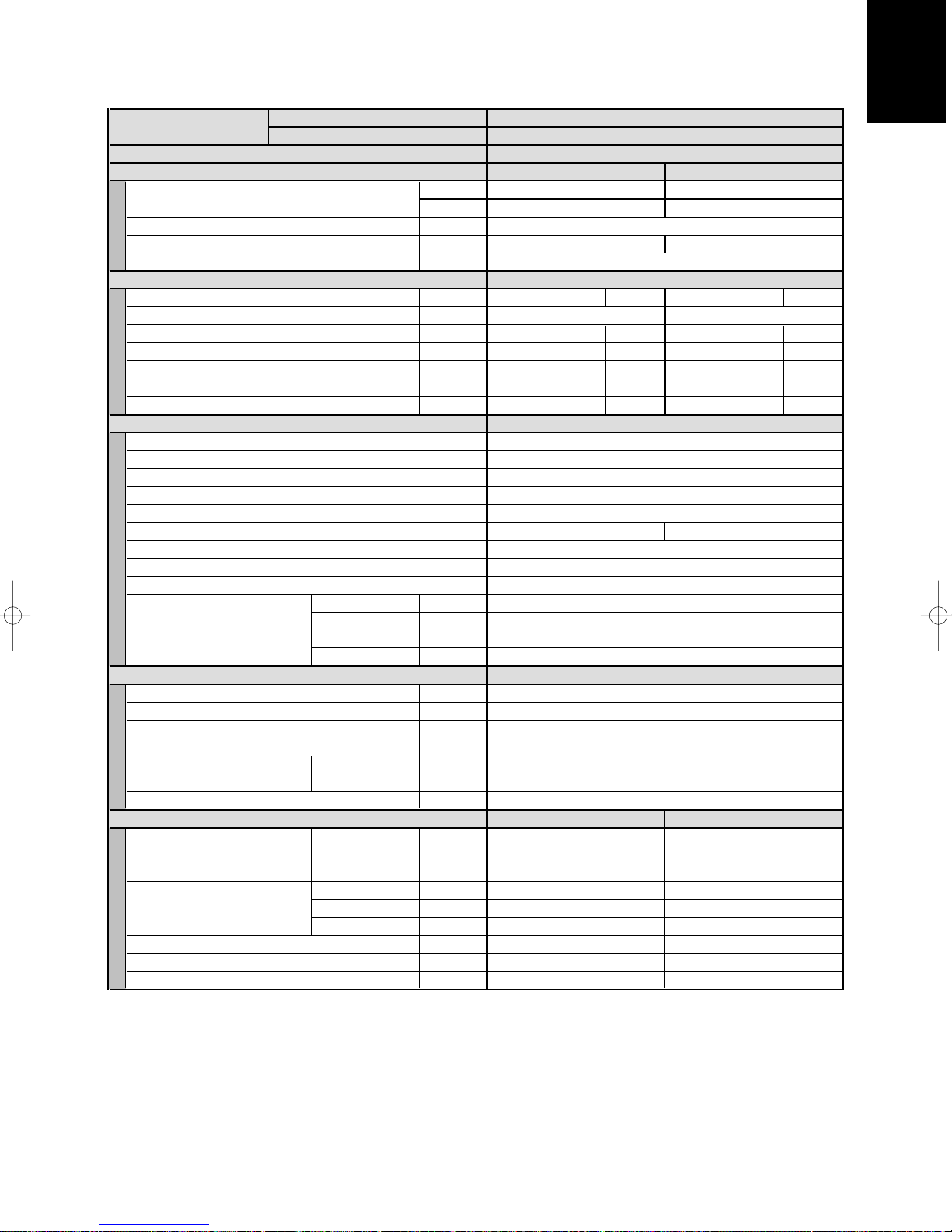
1
1 - 25
1-1. Unit Specifications
Concealed-Duct Type ADS71PH
××
2 / AES125PIH
)
MODEL No. Indoor Unit ADS71PH x 2
POWER SOURCE 220 - 230 - 240 V/1 phase/50/60 Hz
PERFORMANCE
Capacity [minimum~maximum] kW
Air circulation (Hi/Me/Lo) m3/h
Moisture removal (High) Liters/h
External static pressure (High) Pa(mmAq)
ELECTRICAL RATINGS
Voltage rating V
Available voltage range V
Running amperes* A
Max–Running amperes** A
Power input kW
C.O.P W/W
Max. Starting amperes A
FEATURES
Controls/Thermostat control
Timer
Fan speeds Indoor/Outdoor
Airflow direction (Indoor)
Air filter
Remote controller (Option)
Refrigerant control
Drain pump (Drain connection)
Compressor
Operation sound Indoor - Hi/Me/Lo dB - A
Color (Approximate value) Indoor
REFRIGERANT TUBING
Limit of tubing length m (ft.)
Limit of tubing length at shipment m (ft.)
Limit of elevation difference m (ft.)
between the two units
Refrigerant tube Narrow tube mm (in.)
outer diameter Wide tube mm (in.)
Refrigerant amount at shipment kg
DIMENSIONS & WEIGHT
Unit dimensions Height mm (in.)
Package dimensions Height mm (in.)
Net weight kg (lb.)
Shipping weight kg (lb.)
Shipping volume
Cooling:
Rating conditions (*): Indoor air temperature 27°C DB/19°C WB, Outdoor air temperature 35°C DB
Full load conditions (**): Indoor air temperature 32°C DB/23°C WB, Outdoor air temperature 43°C DB
Heating:
Rating conditions (*): Indoor air temperature 20°C DB, Outdoor air temperature 7°C DB/6°C WB
Full load conditions (**): Indoor air temperature 24°C DB, Outdoor air temperature 24°C DB/15.5°C WB
Outdoor Unit AES125PIH
Cooling Heating
12.5 [2.7~14.0] 14.0 [2.7~16.0]
BTU/h
Outdoor - Hi dB - A
Outdoor
Width mm (in.)
Depth mm (in.)
Width mm (in.)
Depth mm (in.)
3
m
(cu. Ft
42,500 [9,200~48,000] 48,000 [9,200~54,500]
2,160/1,800/1,560 (1,080/900/780x2)
7.0 (3.5x2) –
50 (5.1) : at shipment,92 (9.4) : using the booster cable
220 230 240 220
198 - 264 198 - 264
22.2 21.3 20.6 21.9 21.0 20.2
4.39 4.42 4.45 4.33
Microprocessor/I.C.thermostat
ON/OFF 72-hours
3 and Automatic control/Variable
Wired : REM HW Wireless : REM HL
Max.head 50 cm above drain connection (25A , OD32mm)
Rotary(SANYO)
34/30/27, (38/34/30 : using the booster cable)
Munsell 1Y 8.5/0.5
Outdoor unit is higher than indoor unit : 30 (98)
Outdoor unit is lower than indoor unit : 15 (49)
Indoor unit Outdoor unit
310 (12-7/32)
1,000 (39-12/32)
630 (24-26/32)
358 (14-3/32)
1,191 (46-28/32)
783 (30-26/32)
32 (71)
37 (82)
0.334 (11.8)
DATA SUBJECT TO CHANGE WITHOUT NOTICE.
–
Field supply
–
52/53
–
50 (164)
5~30 (16~98)
9.52 (3/8)
15.88 (5/8)
R410A - 3.6
230 240
4.35 4.38
3.22
1230 (48- 7/16)
940 (37)
340 (13-3 /8)
1330 (52-3 /8)
1015 (39-31/32)
409 (16-3/32)
100 (220)
109 (240)
0.552 (19.5)
3.202.85 2.83 2.81 3.23
Page 28

1
1 - 26
)
1-1. Unit Specifications
Concealed-Duct Type ADS100PH / AES100PIC
MODEL No. Indoor Unit ADS100PH
POWER SOURCE 220 - 230 - 240 V/1 phase/50/60 Hz
PERFORMANCE Cooling
Capacity [minimum~maximum] kW
Air circulation (Hi/Me/Lo) m3/h
Moisture removal (High) Liters/h
External static pressure (High) Pa(mmAq)
ELECTRICAL RATINGS
Voltage rating V
Available voltage range V
Running amperes* A
Max–Running amperes** A
Power input kW
C.O.P W/W
Max. Starting amperes A
FEATURES
Controls/Thermostat control
Timer
Fan speeds Indoor/Outdoor
Airflow direction (Indoor)
Air filter
Remote controller (Option)
Refrigerant control
Drain pump (Drain connection)
Compressor
Operation sound Indoor - Hi/Me/Lo dB - A
Outdoor - Hi dB - A
Color (Approximate value) Indoor
Outdoor
REFRIGERANT TUBING
Limit of tubing length m (ft.)
Limit of tubing length at shipment m (ft.)
Limit of elevation difference m (ft.)
between the two units
Refrigerant tube Narrow tube mm (in.)
outer diameter Wide tube mm (in.)
Refrigerant amount at shipment kg
DIMENSIONS & WEIGHT
Unit dimensions Height mm (in.)
Width mm (in.)
Depth mm (in.)
Package dimensions Height mm (in.)
Width mm (in.)
Depth mm (in.)
Net weight kg (lb.)
Shipping weight kg (lb.)
Shipping volume
Cooling:
Rating conditions (*): Indoor air temperature 27°C DB/19°C WB, Outdoor air temperature 35°C DB
Full load conditions (**): Indoor air temperature 32°C DB/23°C WB, Outdoor air temperature 43°C DB
Outdoor Unit AES100PIC
10.0 [2.2~11.2]
34,000 [7,500~38,000]
1,800/1,560/1,260
4.2
198 - 264
17.1 16.4
Microprocessor/I.C.thermostat
ON/OFF 72-hours
3 and Automatic control/Variable
–
Field supply
–
Rotary(SANYO)
51
–
Munsell 1Y 8.5/0.5
50 (164)
5~30 (16~98)
9.52 (3/8)
15.88 (5/8)
R410A - 2.8
DATA SUBJECT TO CHANGE WITHOUT NOTICE.
3
m
BTU/h
(cu. Ft
79 (8.1) : at shipment, 122 (12.4) : using the booster cable
220 230 240
17.9
3.53 3.55
2.83 2.82 2.81
Wired : REM HW
Max.head 50 cm above drain connection (25A , OD32mm)
38/33/31, (42/38/33 : using the booster cable)
Outdoor unit is higher than indoor unit : 30 (98)
Outdoor unit is lower than indoor unit : 15 (49)
Indoor unit Outdoor unit
310 (12-7/32) 780 (30-23/32)
1,480 (58-9/32) 940 (37)
630 (24-26/32) 340 (13-3 /8)
358 (14-3/32) 888 (34-31/32)
1,671 (65-25/32)
783 (30-26/32) 409 (16-3/32)
47 (104) 65 (143)
52 (115) 73 (161)
0.468 (16.5) 0.369 (13.0)
3.56
Wireless : REM HL
1015 (39-31/32)
Page 29
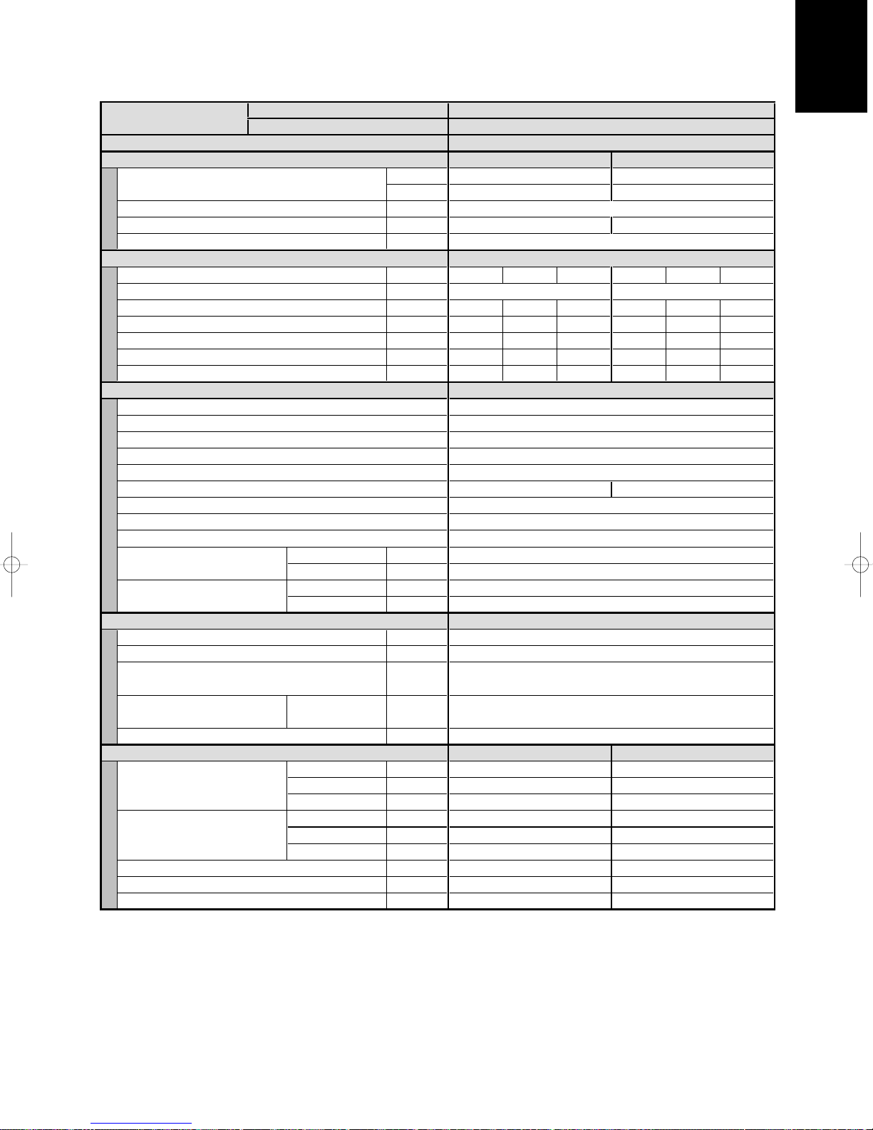
1
1 - 27
)
1-1. Unit Specifications
Concealed-Duct Type ADS100PH / AES100PIH
MODEL No. Indoor Unit ADS100PH
Outdoor Unit AES100PIH
POWER SOURCE 220 - 230 - 240 V/1 phase/50/60 Hz
PERFORMANCE Cooling Heating
Capacity [minimum~maximum] kW
BTU/h
Air circulation (Hi/Me/Lo) m3/h
Moisture removal (High) Liters/h
External static pressure (High) Pa(mmAq)
ELECTRICAL RATINGS
Voltage rating V
Available voltage range V
Running amperes* A
Max–Running amperes** A
Power input kW
C.O.P W/W
Max. Starting amperes A
FEATURES
Controls/Thermostat control
Timer
Fan speeds Indoor/Outdoor
Airflow direction (Indoor)
Air filter
Remote controller (Option)
Refrigerant control
Drain pump (Drain connection)
Compressor
Operation sound Indoor - Hi/Me/Lo dB - A
Outdoor - Hi dB - A
Color (Approximate value) Indoor
Outdoor
REFRIGERANT TUBING
Limit of tubing length m (ft.)
Limit of tubing length at shipment m (ft.)
Limit of elevation difference m (ft.)
between the two units
Refrigerant tube Narrow tube mm (in.)
outer diameter Wide tube mm (in.)
Refrigerant amount at shipment kg
DIMENSIONS & WEIGHT
Unit dimensions Height mm (in.)
Width mm (in.)
Depth mm (in.)
Package dimensions Height mm (in.)
Width mm (in.)
Depth mm (in.)
Net weight kg (lb.)
Shipping weight kg (lb.)
Shipping volume
Cooling:
Rating conditions (*): Indoor air temperature 27°C DB/19°C WB, Outdoor air temperature 35°C DB
Full load conditions (**): Indoor air temperature 32°C DB/23°C WB, Outdoor air temperature 43°C DB
Heating:
Rating conditions (*): Indoor air temperature 20°C DB, Outdoor air temperature 7°C DB/6°C WB
Full load conditions (**): Indoor air temperature 24°C DB, Outdoor air temperature 24°C DB/15.5°C WB
3
m
(cu. Ft
10.0 [2.2~11.2] 11.2 [2.2~12.5]
34,000 [7,500~38,000] 38,000 [7,500~42,500]
1,800/1,560/1,260
4.2 –
79 (8.1) : at shipment, 122 (12.4) : using the booster cable
220 230 240 220 230 240
198 - 264 198 - 264
17.9 17.1
3.53 3.55 3.56 3.28
2.83 2.82
Wired : REM HW Wireless : REM HL
Max.head 50 cm above drain connection (25A , OD32mm)
38/33/31, (42/38/33 : using the booster cable)
Outdoor unit is higher than indoor unit : 30 (98)
Outdoor unit is lower than indoor unit : 15 (49)
Indoor unit Outdoor unit
310 (12-7/32) 780 (30-23/32)
1,480 (58-9/32) 940 (37)
630 (24-26/32)
358 (14-3/32) 888 (34-31/32)
1,671 (65-25/32) 1015 (39-31/32)
783 (30-26/32) 409 (16-3/32)
47 (104)
52 (115) 73 (161)
0.468 (16.5) 0.369 (13.0)
DATA SUBJECT TO CHANGE WITHOUT NOTICE.
16.4 16.6 16.0 15.4
2.81 3.41
Microprocessor/I.C.thermostat
ON/OFF 72-hours
3 and Automatic control/Variable
–
Field supply
–
Rotary(SANYO)
51/52
–
Munsell 1Y 8.5/0.5
50 (164)
5~30 (16~98)
9.52 (3/8)
15.88 (5/8)
R410A - 2.8
3.30 3.31
3.39 3.38
340 (13-3 /8)
65 (143)
Page 30

1
1 - 28
)
1-1. Unit Specifications
Concealed-Duct Type ADS125PH / AES125PIC
MODEL No. Indoor Unit ADS125PH
POWER SOURCE 220 - 230 - 240 V/1 phase/50/60 Hz
PERFORMANCE
Capacity [minimum~maximum] kW
Air circulation (Hi/Me/Lo) m3/h
Moisture removal (High) Liters/h
External static pressure (High) Pa(mmAq)
ELECTRICAL RATINGS
Voltage rating V
Available voltage range V
Running amperes* A
Max–Running amperes** A
Power input kW
C.O.P W/W
Max. Starting amperes A
FEATURES
Controls/Thermostat control
Timer
Fan speeds Indoor/Outdoor
Airflow direction (Indoor)
Air filter
Remote controller (Option)
Refrigerant control
Drain pump (Drain connection)
Compressor
Operation sound Indoor - Hi/Me/Lo dB - A
Outdoor - Hi dB - A
Color (Approximate value) Indoor
Outdoor
REFRIGERANT TUBING
Limit of tubing length m (ft.)
Limit of tubing length at shipment m (ft.)
Limit of elevation difference m (ft.)
between the two units
Refrigerant tube Narrow tube mm (in.)
outer diameter Wide tube mm (in.)
Refrigerant amount at shipment kg
DIMENSIONS & WEIGHT
Unit dimensions Height mm (in.)
Width mm (in.)
Depth mm (in.)
Package dimensions Height mm (in.)
Width mm (in.)
Depth mm (in.)
Net weight kg (lb.)
Shipping weight kg (lb.)
Shipping volume
Cooling:
Rating conditions (*): Indoor air temperature 27°C DB/19°C WB, Outdoor air temperature 35°C DB
Full load conditions (**): Indoor air temperature 32°C DB/23°C WB, Outdoor air temperature 43°C DB
Outdoor Unit AES125PIC
Cooling
12.5 [2.7~14.0]
42,500 [9,200~48,000]
1,980/1,560/1,320
6.6
198 - 264
Microprocessor/I.C.thermostat
ON/OFF 72-hours
3 and Automatic control/Variable
–
Field supply
–
Rotary(SANYO)
52
–
Munsell 1Y 8.5/0.5
50 (164)
5~30 (16~98)
9.52 (3/8)
15.88 (5/8)
R410A - 3.6
DATA SUBJECT TO CHANGE WITHOUT NOTICE.
3
m
BTU/h
(cu. Ft
78 (8.0) : at shipment, 113 (11.5) : using the booster cable
220 230
22.0 21.1
4.34 4.36 4.37
2.88 2.87 2.86
Wired : REM HW Wireless : REM HL
Max.head 50 cm above drain connection (25A , OD32mm)
40/37/33, (44/40/37 : using the booster cable)
Outdoor unit is higher than indoor unit : 30 (98)
Outdoor unit is lower than indoor unit : 15 (49)
Indoor unit Outdoor unit
310 (12-7/32)
1,480 (58-9/32)
630 (24-26/32)
358 (14-3/32)
1,671 (65-25/32)
783 (30-26/32)
47 (104)
52 (115)
0.468 (16.5) 0.552 (19.5)
240
20.3
1230 (48- 7/16)
940 (37)
340 (13-3 /8)
1330 (52-3 /8)
1015 (39-31/32)
409 (16-3/32)
100 (220)
109 (240)
Page 31

1
1 - 29
)
1-1. Unit Specifications
Concealed-Duct Type ADS125PH / AES125PIH
MODEL No. Indoor Unit ADS125PH
Outdoor Unit AES125PIH
POWER SOURCE 220 - 230 - 240 V/1 phase/50/60 Hz
PERFORMANCE
Capacity [minimum~maximum] kW
BTU/h
Air circulation (Hi/Me/Lo) m3/h
Moisture removal (High) Liters/h
External static pressure (High) Pa(mmAq)
ELECTRICAL RATINGS
Voltage rating V
Available voltage range V
Running amperes* A
Max–Running amperes** A
Power input kW
C.O.P W/W
Max. Starting amperes A
FEATURES
Controls/Thermostat control
Timer
Fan speeds Indoor/Outdoor
Airflow direction (Indoor)
Air filter
Remote controller (Option)
Refrigerant control
Drain pump (Drain connection)
Compressor
Operation sound Indoor - Hi/Me/Lo dB - A
Outdoor - Hi dB - A
Color (Approximate value) Indoor
Outdoor
REFRIGERANT TUBING
Limit of tubing length m (ft.)
Limit of tubing length at shipment m (ft.)
Limit of elevation difference m (ft.)
between the two units
Refrigerant tube Narrow tube mm (in.)
outer diameter Wide tube mm (in.)
Refrigerant amount at shipment kg
DIMENSIONS & WEIGHT
Unit dimensions Height mm (in.)
Width mm (in.)
Depth mm (in.)
Package dimensions Height mm (in.)
Width mm (in.)
Depth mm (in.)
Net weight kg (lb.)
Shipping weight kg (lb.)
Shipping volume
Cooling:
Rating conditions (*): Indoor air temperature 27°C DB/19°C WB, Outdoor air temperature 35°C DB
Full load conditions (**): Indoor air temperature 32°C DB/23°C WB, Outdoor air temperature 43°C DB
Heating:
Rating conditions (*): Indoor air temperature 20°C DB, Outdoor air temperature 7°C DB/6°C WB
Full load conditions (**): Indoor air temperature 24°C DB, Outdoor air temperature 24°C DB/15.5°C WB
3
m
(cu. Ft
220 230 240 220 230 240
22.0 21.1 20.3 21.7 20.7 19.9
4.34 4.36 4.37 4.29 4.29 4.31
2.88 2.87 2.86 3.26
Cooling Heating
12.5 [2.7~14.0] 14.0 [2.7~16.0]
42,500 [9,200~48,000] 48,000 [9,200~54,500]
1,980/1,560/1,320
6.6 –
78 (8.0) : at shipment, 113 (11.5) : using the booster cable
198 - 264 198 - 264
Microprocessor/I.C.thermostat
ON/OFF 72-hours
3 and Automatic control/Variable
–
Field supply
Wired : REM HW Wireless : REM HL
–
Max.head 50 cm above drain connection (25A , OD32mm)
Rotary(SANYO)
40/37/33, (44/40/37 : using the booster cable)
52/53
–
Munsell 1Y 8.5/0.5
50 (164)
5~30 (16~98)
Outdoor unit is higher than indoor unit : 30 (98)
Outdoor unit is lower than indoor unit : 15 (49)
9.52 (3/8)
15.88 (5/8)
R410A - 3.6
Indoor unit Outdoor unit
310 (12-7/32)
1,480 (58-9/32)
630 (24-26/32)
358 (14-3/32) 1330 (52-3 /8)
1,671 (65-25/32) 1015 (39-31/32)
783 (30-26/32) 409 (16-3/32)
47 (104)
52 (115) 109 (240)
DATA SUBJECT TO CHANGE WITHOUT NOTICE.
3.26 3.25
1230 (48- 7/16)
940 (37)
340 (13-3 /8)
100 (220)
0.552 (19.5)0.468 (16.5)
Page 32

1
1 - 30
1-2. Major Component Specifications
(A) Indoor Units
Wall-Mounted Type AWS36-45PH
MODEL No.
Source
Controller P.C.B. Ass’y
Fan (Number…diameter) mm
Fan motor
Model…Nominal output W
Source
No.of pole…rpm (230 V, High) rpm
Coil resistance BRN – WHT : 490.5 ORG – YEL : 39.18
(Ambient temperature 20°C) WHT – VLT : 78.43 YEL – PNK : 213.5
VLT – ORG : 62.63
Safety device
Operating temperature
( 17AM033E5-4 )
Operating temperature
( 9700k211-215 )
Run capacitor
Electronic expansion valve
Open °C
Close °C
Open °C
Close °C
VAC, µF
AWS36PH / AWS45PH
220 - 230 - 240 V / 1 phase / 50/60 Hz
CR-KR74GXH56 (Microprocessor)
Cross-flow ( 1…ø88 / L740 )
UF4Q-31G5P-S…12W
220 - 230 - 240 V / 1 phase / 50/60 Hz
4P…1,164
130 ± 5
83 ± 15
130 ± 8
79 ± 15
440 VAC, 1.0µF
Coil
Coil resistance (at 20°C)
Valve body
Heat exchanger
Coil
Rows…fin pitch mm
Face area
Panel
Model No.
Dew proof heater
Auto louver motor
Coil resistance (at 25°C)
Drain Pump
Rated
Total head & capacity
VAC, W
–
: – YEL –ORG – GRY
RED – GRY : – BLK – GRY : –
–
Aluminum plate fin / Copper tube
2…1.3
2
m
0.231
–
–
–
–
–
–
–
GRY
: –
Page 33

1
1 - 31
1-2. Major Component Specifications
(A) Indoor Units
Wall-Mounted Type AWS56PH
MODEL No.
Source
Controller P.C.B. Ass’y
Fan (Number…diameter) mm
Fan motor
Model…Nominal output W
Source
No.of pole…rpm (230 V, High) rpm
Coil resistance BRN - WHT : 490.5 ORG – YEL : 39.18
(Ambient temperature 20°C) WHT – VLT : 78.43 YEL – PNK : 213.5
Safety device
Operating temperature
( 17AM033E5-4 )
Operating temperature
( 9700k211-215 )
Run capacitor
Electronic expansion valve
Coil
Coil resistance (at 20°C)
Open °C 130 ± 5
Close °C 83 ± 15
Open °C
Close °C
VAC, µF 440 VAC, 1.2µF
ORG – GRY
220 - 230 - 240 V / 1 phase / 50/60 Hz
CR-KR74GXH56 (Microprocessor)
Cross-flow ( 1…ø88 / L740 )
220 - 230 - 240 V / 1 phase / 50/60 Hz
VLT – ORG : 62.63
AWS56PH
UF4Q-31G5P-S…12W
4P…1,205
130 ± 8
79 ± 15
–
: – YEL – GRY : –
Valve body
Heat exchanger
Coil
Rows…fin pitch mm
Face area
Panel
Model No.
Dew proof heater
Auto louver motor
Coil resistance (at 25°C)
Drain Pump
Rated
Total head & capacity
VAC, W
RED – GRY : – BLK – GRY : –
–
Aluminum plate fin / Copper tube
2…1.3
2
m
0.231
–
–
–
–
–
–
–
Page 34

1
1 - 32
1-2. Major Component Specifications
(A) Indoor Units
Wall-Mounted Type AWS71PH
MODEL No.
Source
Controller P.C.B. Ass’y
Fan (Number…diameter) mm
Fan motor
Model…Nominal output W
Source
No.of pole…rpm (230 V, High) rpm
Coil resistance BRN – WHT : 306.9 ORG – YEL : 23.12
(Ambient temperature 20°C) WHT – VLT : 54.58 YEL – PNK : 96.62
Safety device
Operating temperature
( 17AM033E5-4 )
Operating temperature
( 9700k211-215 )
Run capacitor
Electronic expansion valve
Coil –
Coil resistance (at 20°C)
Open °C 130 ± 5
Close °C
Open °C 130 ± 5
Close °C
VAC, µF 440 VAC, 1.8µF
ORG – GRY : – YEL – GRY : –
220 - 230 - 240 V / 1 phase / 50/60 Hz
CR-KR254GXH56 (Microprocessor)
Cross-flow ( 1…ø100 / L848 )
220 - 230 - 240 V / 1 phase / 50/60 Hz
VLT – ORG : 33.91
AWS71PH
KFT4Q-31A5P-S…27W
4P…1,147
83 ± 15
79 ± 15
Valve body
Heat exchanger
Coil
Rows…fin pitch mm
Face area
Panel
Model No.
Dew proof heater
Auto louver motor
Coil resistance (at 25°C)
Drain Pump
Rated
Total head & capacity
VAC, W –
RED – GRY : – BLK – GRY : –
–
Aluminum plate fin / Copper tube
2…1.3
2
m
0.329
–
–
–
–
–
–
Page 35

1
1 - 33
1-2. Major Component Specifications
(A) Indoor Units
Ceiling-Mounted Type ACS71PH
MODEL No.
Source
Controller P.C.B. Ass’y
Fan (Number…diameter) mm
Fan motor
Model…Nominal output W
Source
No.of pole…rpm (230 V, High) rpm
Coil resistance
(Ambient temperature 20°C)
Run capacitor
Safety device
Electronic expansion valve
Coil
Coil resistance (at 20°C) ORG – GRY : – YEL – GRY : –
Valve body
Heat exchanger
Coil
VAC, µF–
220 - 230 - 240 V / 1 phase / 50/60 Hz
CR-SRP50A-B (Microprocessor)
RED – GRY : – BLK – GRY : –
Aluminum plate fin / Copper tube
ACS71PH
Centrifugal ( 3…ø140 )
DK8-63B280H…40W
8P…980
RED – WHT : 53.0
WHT – BLK : 53.0
BLK – RED : 53.0
Thermal protector, fuse
–
–
Rows…fin pitch mm
Face area
Panel
Model No.
Dew proof heater
Auto louver motor
Coil resistance (at 25°C)
Drain Pump
Rated
Total head & capacity
VAC, W
3…1.4
2
m
0.222
–
–
–
–
–
–
–
Page 36

1
1 - 34
1-2. Major Component Specifications
(A) Indoor Units
Ceiling-Mounted Type ACS100PH
MODEL No.
Source
Controller P.C.B. Ass’y
Fan (Number…diameter) mm
Fan motor
Model…Nominal output W
Source
No.of pole…rpm (230 V, High) rpm
Coil resistance RED – WHT : 37.0
(Ambient temperature 20°C) WHT – BLK : 37.0
Run capacitor
Safety device
Electronic expansion valve
Coil
Coil resistance (at 20°C) ORG – GRY : – YEL – GRY : –
Valve body
Heat exchanger
Coil Aluminum plate fin / Copper tube
VAC, µF–
220 - 230 - 240 V / 1 phase / 50/60 Hz
CR-SRP50A-B (Microprocessor)
RED – GRY : – BLK – GRY : –
ACS100PH
Centrifugal ( 4…ø140 )
DK8-123B280H…80W
8P…1040
BLK – RED : 37.0
Thermal protector, fuse
–
–
Rows…fin pitch mm
Face area
Panel
Model No.
Dew proof heater
Auto louver motor
Coil resistance (at 25°C)
Drain Pump
Rated
Total head & capacity
VAC, W –
3…1.4
2
m
0.326
–
–
–
–
–
–
Page 37

1
1 - 35
1-2. Major Component Specifications
(A) Indoor Units
Ceiling-Mounted Type ACS125PH
MODEL No.
Source
Controller P.C.B. Ass’y
Fan (Number…diameter) mm
Fan motor
Model…Nominal output W
Source
No.of pole…rpm (230 V, High) rpm
Coil resistance
(Ambient temperature 20°C)
Run capacitor
Safety device
Electronic expansion valve
Coil
Coil resistance (at 20°C) ORG – GRY : – YEL – GRY : –
Valve body
VAC, µF
ACS125PH
220 - 230 - 240 V / 1 phase / 50/60 Hz
CR-SRP50A-B (Microprocessor)
Centrifugal ( 4…ø140 )
DK8-123B280H…80W
8P…1100
RED – WHT : 37.0
WHT – BLK : 37.0
BLK – RED : 37.0
–
Thermal protector, fuse
–
RED – GRY : – BLK – GRY : –
–
Heat exchanger
Coil
Rows…fin pitch mm
Face area
Panel
Model No.
Dew proof heater
Auto louver motor
Coil resistance (at 25°C)
Drain Pump
Rated
Total head & capacity
VAC, W –
Aluminum plate fin / Copper tube
3…1.4
2
m
0.326
–
–
–
–
–
–
Page 38

1
1 - 36
1-2. Major Component Specifications
(A) Indoor Units
Concealed-Duct ADS71PH
MODEL No.
Source
Controller P.C.B. Ass’y
Fan (Number…diameter) mm
Fan motor
Model…Nominal output W
Source
No.of pole…rpm (230 V, High) rpm
Coil resistance Ω BRN - WHT : 74.72 ORG – YEL : 9.588
(Ambient temperature 20°C) WHT – VLT : 19.14 YEL – BLK : 10.52
Safety device
Operating temperature
Run capacitor
Electronic expansion valve
Coil
Coil resistance (at 20°C) Ω ORG – GRY : – YEL – GRY : –
Open °C
Close °C
VAC, µF 450 VAC, 5.0µF
220 - 230 - 240 V / 1 phase / 50/60 Hz
CR-TRP50A-B (Microprocessor)
220 - 230 - 240 V / 1 phase / 50/60 Hz
VLT – ORG : 10.52 BLK – PNK : 21.72
ADS71PH
Centrifugal ( 2…ø190 )
KFG4X-71B5P…70W
4P…1,063
130 ± 5
( 115 ± 5 )
–
: – BLK – GRY : –RED – GRY
Valve body –
Heat exchanger
Coil
Rows…fin pitch mm
Face area
Panel
Model No.
Dew proof heater
Auto louver motor
Coil resistance (at 25°C) Ω
Drain Pump
Rated
Total head & capacity
VAC, W AC230 V, 50 Hz, 12 W
2
m
Aluminum plate fin / Copper tube
500 mm, 400 cc/min
3…1.5
0.189
–
–
–
–
ADP-1413
Page 39

1
1 - 37
1-2. Major Component Specifications
(A) Indoor Units
Concealed-Duct ADS100PH
MODEL No.
Source
Controller P.C.B. Ass’y
Fan (Number…diameter) mm
Fan motor
Model…Nominal output W
Source
No.of pole…rpm (230 V, High) rpm
Coil resistance Ω BRN – WHT : 25.79 ORG – YEL : 5.792
(Ambient temperature 20°C) WHT – VLT : 5.086 YEL – BLK : 6.746
Safety device
Operating temperature
Run capacitor
Electronic expansion valve
Coil
Coil resistance (at 20°C) Ω ORG – GRY : – YEL – GRY : –
Valve body
Open °C 130 ± 5
Close °C ( 115 ± 5 )
VAC, µF 450 VAC, 6.0µF
220 - 230 - 240 V / 1 phase / 50/60 Hz
CR-TRP50A-B (Microprocessor)
220 - 230 - 240 V / 1 phase / 50/60 Hz
VLT – ORG : 8.626 BLK – PNK : 6.361
RED – GRY
ADS100PH
Centrifugal ( 3…ø190 )
KFC4X-141A5P…160W
4P…1,207
–
: – BLK –
–
GRY : –
Heat exchanger
Coil
Rows…fin pitch mm
Face area
Panel
Model No.
Dew proof heater
Auto louver motor
Coil resistance (at 25°C) Ω
Drain Pump
Rated
Total head & capacity
VAC, W
Aluminum plate fin / Copper tube
3…2.0
2
m
0.308
–
–
–
–
ADP-1413
AC230 V, 50 Hz, 12 W
500 mm, 400 cc/min
Page 40

1
1 - 38
1-2. Major Component Specifications
(A) Indoor Units
Concealed-Duct ADS125PH
MODEL No.
Source
Controller P.C.B. Ass’y
Fan (Number…diameter) mm
Fan motor
Model…Nominal output W
Source
No.of pole…rpm (230 V, High) rpm
Coil resistance Ω BRN - WHT : 25.79 ORG – YEL : 5.792
(Ambient temperature 20°C) WHT – VLT : 5.086 YEL – BLK : 6.746
Safety device
Operating temperature
Run capacitor
Electronic expansion valve
Coil
Coil resistance (at 20°C) Ω ORG – GRY : – YEL – GRY : –
Valve body –
Open °C 130 ± 5
Close °C ( 115 ± 5 )
VAC, µF 450 VAC, 8.0µF
220 - 230 - 240 V / 1 phase / 50/60 Hz
CR-TRP50A-B (Microprocessor)
220 - 230 - 240 V / 1 phase / 50/60 Hz
VLT – ORG : 8.626 BLK – PNK : 6.361
ADS125PH
Centrifugal ( 3…ø190 )
KFC4X-141A5P…160W
4P…1,207
–
BLK – GRY : –RED – GRY : –
Heat exchanger
Coil
Rows…fin pitch mm
Face area
Panel
Model No.
Dew proof heater
Auto louver motor
Coil resistance (at 25°C) Ω
Drain Pump
Rated
Total head & capacity
VAC, W
Aluminum plate fin / Copper tube
3…2.0
2
m
0.308
–
–
–
–
ADP-1413
AC230 V, 50 Hz, 12 W
500 mm, 400 cc/min
Page 41

1
1 - 39
1-2. Major Component Specifications
(B) Outdoor Units
AES71PIH
MODEL No.
Source
Controller P.C.B. Ass’y
Control circuit fuse
Compressor
Model…..number
Source
Nominal output W
Compressor oil cc
Coil resistance Ω C – R : 0.665 R – S : 0.665
(Ambient temperature 25°C) C – S : 0.665
Safety control
Overload relay models
Operating temperature Open °C
Close °C
Crank case heater
Refrigerant amount at shipment kg
High pressure switch
Set pressure OFF
ON
kg/cm
kg/cm
2
2
220 - 230 - 240 V / 1 phase / 50/60 Hz
CR-CR254GVH56 (Microprocessor)
126 V (DC) / 3 phase / 60 Hz (Inverter drive)
Discharge temperature control
AES71PIH
250 V, 25 A
C-7RVN153H0V
1,500
650
–
–
–
R410A - 1.9
–
Fan
Number…diameter mm
Air circulation (Hi)
Fan speeds (Max.)
Fan motor
Model No.
Source
No. of pole
Nominal output W
Coil resistance Ω RED – WHT : 30.5 WHT – BLU : 30.5
(Ambient temperature 20°C) BLU – RED : 30.5
Safety device
Operating temperature Open °C
Close °C
Run capacitor VAC, µF
Heat exchange
Coil
Rows…..fin pitch mm
Face area
3
/h
m
2
m
~800 rpm (Inverter drive control)
Aluminium plate fin / Copper tube
Propeller
1…..ø460
3,000
DAJ12-95A61A
~280 V / 3 phase
8
90
–
–
–
–
1…..1.6
0.675
Page 42

1
1 - 40
1-2. Major Component Specifications
(B) Outdoor Units
AES100PIH
MODEL No.
Source
Controller P.C.B. Ass’y
Control circuit fuse
Compressor
Model…..number
Source
Nominal output W
Compressor oil cc
Coil resistance Ω C – R : 0.665 R – S : 0.665
(Ambient temperature 25°C) C – S : 0.665
Safety control
Overload relay models
Operating temperature Open °C
Close °C
Crank case heater
Refrigerant amount at shipment kg
High pressure switch
Set pressure OFF
ON
kg/cm
kg/cm
2
2
220 - 230 - 240 V / 1 phase / 50/60 Hz
CR-CR254GVH56 (Microprocessor)
126 V (DC) / 3 phase / 60 Hz (Inverter drive)
AES100PIH
250 V, 25 A
C-7RVN153H0V
1,500
650
Discharge temperature control
–
–
–
R410A - 2.8
–
Fan
Number…diameter mm
Air circulation (Hi)
Fan speeds (Max.)
Fan motor
Model No.
Source
No. of pole
Nominal output W
Coil resistance Ω RED – WHT : 30.5 WHT – BLU : 30.5
(Ambient temperature 20°C) BLU – RED : 30.5
Safety device
Operating temperature Open °C
Close °C
Run capacitor VAC, µF
Heat exchange
Coil
Rows…..fin pitch mm
Face area
3
m
/h
~830 rpm (Inverter drive control)
Aluminium plate fin / Copper tube
2
m
Propeller
1…..ø460
3,300
DAJ12-95A61A
~280 V / 3 phase
8
90
–
–
–
–
2…..1.8
0.675
Page 43

1
1 - 41
1-2. Major Component Specifications
(B) Outdoor Units
AES125PIH
MODEL No.
Source
Controller P.C.B. Ass’y
Control circuit fuse
Compressor
Model…..number
Source
Nominal output W
Compressor oil cc
Coil resistance
(Ambient temperature 25°C) C – S : 0.169
Safety control
Overload relay models
Operating temperature Open °C
Close °C
Crank case heater
Refrigerant amount at shipment kg
High pressure switch
Set pressure OFF
ON
kg/cm
kg/cm
2
2
C – R : 0.169 R – S : 0.169
AES125PIH
220 - 230 - 240 V / 1 phase / 50/60 Hz
CR-CR254GVH56 (Microprocessor)
250 V, 25 A
C-9RVN273H0W
126 V (DC) / 3 phase / 60 Hz (Inverter drive)
2,700
1,900
Discharge temperature control
–
–
–
R410A - 3.6
–
Fan
Number…diameter mm
Air circulation (Hi)
Fan speeds (Max.)
Fan motor
Model No.
Source
No. of pole
Nominal output W
Coil resistance RED – WHT : 30.5 WHT – BLU : 30.5
(Ambient temperature 20°C) BLU – RED : 30.5
Safety device
Operating temperature Open °C
Close °C
Run capacitor VAC, µF
Heat exchange
Coil
Rows…..fin pitch mm
Face area
3
/h
m
2
m
~800 rpm (Inverter drive control)
Aluminium plate fin / Copper tube
Propeller
2…..ø460
6,000
DAJ12-95A61A,B
~280 V / 3 phase
8
90
–
–
–
–
2…..2.0
1.080
Page 44

1
1 - 42
1-2. Major Component Specifications
(B) Outdoor Units
AES71PIC
MODEL No.
Source
Controller P.C.B. Ass’y
Control circuit fuse
Compressor
Model…..number
Source
Nominal output W
Compressor oil cc
Coil resistance Ω C – R : 0.665 R – S : 0.665
(Ambient temperature 25°C) C – S : 0.665
Safety control
Overload relay models
Operating temperature Open °C
Close °C
Crank case heater
Refrigerant amount at shipment kg
High pressure switch
Set pressure OFF
ON
kg/cm
kg/cm
2
2
220 - 230 - 240 V / 1 phase / 50/60 Hz
CR-CR254GVH56 (Microprocessor)
126 V (DC) / 3 phase / 60 Hz (Inverter drive)
AES71PIC
250 V, 25 A
C-7RVN153H0V
1,500
650
Discharge temperature control
–
–
–
R410A - 1.9
–
Fan
Number…diameter mm
Air circulation (Hi)
Fan speeds (Max.)
Fan motor
Model No.
Source
No. of pole
Nominal output W
Coil resistance Ω RED – WHT : 30.5 WHT – BLU : 30.5
(Ambient temperature 20°C) BLU – RED : 30.5
Safety device
Operating temperature Open °C
Close °C
Run capacitor VAC, µF
Heat exchange
Coil
Rows…..fin pitch mm
Face area
3
/h
m
2
m
~800 rpm (Inverter drive control)
Aluminium plate fin / Copper tube
Propeller
1…..ø460
3,000
DAJ12-95A61A
~280 V / 3 phase
8
90
–
–
–
–
1…..1.6
0.675
Page 45

1
1 - 43
1-2. Major Component Specifications
(B) Outdoor Units
AES100PIC
MODEL No.
Source
Controller P.C.B. Ass'y
Control circuit fuse
Compressor
Model…..number
Source
Nominal output W
Compressor oil cc
Coil resistance Ω C – R : 0.665 R – S : 0.665
(Ambient temperature 25°C) C – S : 0.665
Safety control
Overload relay models
Operating temperature Open °C
Close °C
Crank case heater
Refrigerant amount at shipment kg
High pressure switch
Set pressure OFF
ON
kg/cm
kg/cm
2
2
220 - 230 - 240 V / 1 phase / 50/60 Hz
CR-CR254GVH56 (Microprocessor)
126 V (DC) / 3 phase / 60 Hz (Inverter drive)
Discharge temperature control
AES100PIC
250 V, 25 A
C-7RVN153H0V
1,500
650
–
–
–
R410A - 2.8
–
Fan
Number…diameter mm
Air circulation (Hi)
Fan speeds (Max.)
Fan motor
Model No.
Source
No. of pole
Nominal output W
Coil resistance Ω RED – WHT : 30.5 WHT – BLU : 30.5
(Ambient temperature 20°C) BLU – RED : 30.5
Safety device
Operating temperature Open °C
Close °C
Run capacitor VAC, µF
Heat exchange
Coil
Rows…..fin pitch mm
Face area
3
m
/h
~830 rpm (Inverter drive control)
Aluminium plate fin / Copper tube
2
m
Propeller
1…..ø460
3,300
DAJ12-95A61A
~280 V / 3 phase
8
90
–
–
–
–
2…..1.8
0.675
Page 46

1
1 - 44
1-2. Major Component Specifications
(B) Outdoor Units
AES125PIC
MODEL No.
Source
Controller P.C.B. Ass’y
Control circuit fuse
Compressor
Model…..number
Source
Nominal output W
Compressor oil cc
Coil resistance Ω C – R : 0.169 R – S : 0.169
(Ambient temperature 25°C) C – S : 0.169
Safety control
Overload relay models
Operating temperature Open °C
Close °C
Crank case heater
Refrigerant amount at shipment kg
High pressure switch
Set pressure OFF
ON
kg/cm
kg/cm
2
2
220 - 230 - 240 V / 1 phase / 50/60 Hz
CR-CR254GVH56 (Microprocessor)
126 V (DC) / 3 phase / 60 Hz (Inverter drive)
AES125PIC
250 V, 25 A
C-9RVN273H0W
2,700
1,900
Discharge temperature control
–
–
–
R410A - 3.6
–
Fan
Number…diameter mm
Air circulation (Hi)
Fan speeds (Max.)
Fan motor
Model No.
Source
No. of pole
Nominal output W
Coil resistance Ω RED – WHT : 30.5 WHT – BLU : 30.5
(Ambient temperature 20°C) BLU – RED : 30.5
Safety device
Operating temperature Open °C
Close °C
Run capacitor VAC, µF
Heat exchange
Coil
Rows…..fin pitch mm
Face area
3
/h
m
2
m
~800 rpm (Inverter drive control)
Aluminium plate fin / Copper tube
Propeller
2…..ø460
6,000
DAJ12-95A61A,B
~280 V / 3 phase
8
90
–
–
–
–
2…..2.0
1.080
Page 47

1
1 - 45
1-3. Other Component Specifications
Wall-Mounted Type AWS36 - 71PH
MODEL No. Indoor Unit
Power Transformer
Rated
Primary VAC, Hz
Secondary
Coil resistance Ω
Thermal cut off temperature °C
Thermistor (Coil sensor) : TH
Resistance KΩ –10°C : 23.7 ± 5 % , 20°C : 6.5 ± 5 %
– 5°C : 18.8 ± 5 % , 30°C : 4.4 ± 5 %
0°C : 15.0 ± 5 % , 40°C : 3.1 ± 5 %
5°C : 12.1 ± 5 % , 45°C : 2.6 ± 5 %
10°C : 9.7 ± 5 % , 50°C : 2.1 ± 5 %
Thermistor (Room sensor) :
Resistance KΩ 0°C : 16.5 ± 5 % , 40°C : 2.7 ± 5 %
5°C : 12.8 ± 5 % , 45°C : 2.2 ± 5 %
10°C : 10.0 ± 5 % , 50°C : 1.8 ± 5 %
20°C : 6.3 ± 5 % , 55°C : 1.5 ± 5 %
30°C : 4.0 ± 5 % ,
Electronic expansion valve
Valve body
Coil
Drain Pump
Rated
Float switch
Rated (Contact rated)
AWS36 - 71PH
–
–
–
–
–
–
–
Page 48

1
1 - 46
1-3. Other Component Specifications
Ceiling-Mounted Type ACS71 - 125PH
MODEL No. Indoor Unit
Power Transformer
Rated
Primary VAC, Hz
Secondary
Coil resistance Ω
Thermal cut off temperature °C
Thermistor (Coil sensor) : TH
Resistance KΩ –10°C : 23.7 ± 5 % , 20°C : 6.5 ± 5 %
– 5°C : 18.8 ± 5 % , 30°C : 4.4 ± 5 %
0°C : 15.0 ± 5 % , 40°C : 3.1 ± 5 %
5°C : 12.1 ± 5 % , 45°C : 2.6 ± 5 %
10°C : 9.7 ± 5 % , 50°C : 2.1 ± 5 %
Thermistor (Room sensor) :
Resistance KΩ 0°C : 16.5 ± 5 % , 40°C : 2.7 ± 5 %
5°C : 12.8 ± 5 % , 45°C : 2.2 ± 5 %
10°C : 10.0 ± 5 % , 50°C : 1.8 ± 5 %
20°C : 6.3 ± 5 % , 55°C : 1.5 ± 5 %
30°C : 4.0 ± 5 % ,
Electronic expansion valve
Valve body
Coil
Drain Pump
Rated
Float switch
Rated (Contact rated)
ACS71 - 125PH
–
–
–
–
–
–
–
–
–
–
–
–
FS-0218-102
Page 49

1
1 - 47
1-3. Other Component Specifications
Concealed-Duct Type ADS71 - 125PH
MODEL No. Indoor Unit
Power Transformer
Rated
Primary VAC, Hz
Secondary
Coil resistance Ω
Thermal cut off temperature °C
Thermistor (Coil sensor) : TH
Resistance KΩ –10°C : 23.7 ± 5 % , 20°C : 6.5 ± 5 %
– 5°C : 18.8 ± 5 % , 30°C : 4.4 ± 5 %
0°C : 15.0 ± 5 % , 40°C : 3.1 ± 5 %
5°C : 12.1 ± 5 % , 45°C : 2.6 ± 5 %
10°C : 9.7 ± 5 % , 50°C : 2.1 ± 5 %
Thermistor (Room sensor) :
Resistance KΩ 0°C : 16.5 ± 5 % , 40°C : 2.7 ± 5 %
5°C : 12.8 ± 5 % , 45°C : 2.2 ± 5 %
10°C : 10.0 ± 5 % , 50°C : 1.8 ± 5 %
20°C : 6.3 ± 5 % , 55°C : 1.5 ± 5 %
30°C : 4.0 ± 5 % ,
Electronic expansion valve
Valve body
Coil
Drain Pump
Rated
Float switch
Rated (Contact rated)
ADS71 - 125PH
–
–
–
ADP-1413
AC230 V°C 12 W
FS-0218-102
Page 50

1
1 - 48
1-3. Other Component Specifications
Outdoor Units AES71PIH
8
MODEL No. Outdoor Unit
Power Transformer
Rated
Primary VAC, Hz
Secondary
Coil resistance Ω WHT – WHT : 300
Thermal cut off temperature °C
Thermistor (Coil sensor) : TH7
Resistance KΩ –10°C : 23.7 ± 5 % , 20°C : 6.5 ± 5 %
Thermistor (Discharge gas sensor) : TH
Resistance KΩ 60°C : 13.8 , 90°C : 5.1
Relay (Comp. Magnetic Contactor)
Coil rated VAC
Contact rating VAC, A
Coil resistance (at 25°C) Ω
Solenoid coil or 4 way valve
4 way valve
Solenoid coil
AES71PIH
–
–
230 V, 50 Hz
14 V, 0.4A
BRN – BRN : 2.2
–
PBC - 41E - S4
– 5°C : 18.8 ± 5 % , 30°C : 4.4 ± 5 %
0°C : 15.0 ± 5 % , 40°C : 3.1 ± 5 %
5°C : 12.1 ± 5 % , 45°C : 2.6 ± 5 %
10°C : 9.7 ± 5 % , 50°C : 2.1 ± 5 %
PTC - 51H - S1
70°C : 9.7 , 100°C : 3.8
75°C : 8.2 , 110°C : 2.8
80°C : 7.0 , 120°C : 2.2
85°C : 5.9 , 130°C : 1.7
–
–
–
–
STF-01AJ512D1
–
Page 51

1
1 - 49
1-3. Other Component Specifications
Outdoor Units AES100PIH
8
MODEL No. Outdoor Unit
Power Transformer
Rated
Primary VAC, Hz
Secondary
Coil resistance Ω WHT – WHT : 300
Thermal cut off temperature °C
Thermistor (Coil sensor) : TH7
Resistance KΩ –10°C : 23.7 ± 5 % , 20°C : 6.5 ± 5 %
– 5°C : 18.8 ± 5 % , 30°C : 4.4 ± 5 %
0°C : 15.0 ± 5 % , 40°C : 3.1 ± 5 %
5°C : 12.1 ± 5 % , 45°C : 2.6 ± 5 %
10°C : 9.7 ± 5 % , 50°C : 2.1 ± 5 %
Thermistor (Discharge gas sensor) : TH
Resistance KΩ 60°C : 13.8 , 90°C : 5.1
70°C : 9.7 , 100°C : 3.8
75°C : 8.2 , 110°C : 2.8
80°C : 7.0 , 120°C : 2.2
85°C : 5.9 , 130°C : 1.7
Relay (Comp. Magnetic Contactor)
Coil rated VAC
Contact rating VAC, A
Coil resistance (at 25°C) Ω
Solenoid coil or 4 way valve
4 way valve
Solenoid coil
AES100PIH
–
–
230 V, 50 Hz
14 V, 0.4A
BRN – BRN : 2.2
–
PBC - 41E - S4
PTC - 51H - S1
–
–
–
–
STF-01AJ512D1
–
Page 52

1
1 - 50
1-3. Other Component Specifications
Outdoor Units AES125PIH
8
MODEL No. Outdoor Unit
Power Transformer
Rated
Primary VAC, Hz
Secondary
Coil resistance Ω WHT – WHT : 300
Thermal cut off temperature °C
Thermistor (Coil sensor) : TH7
Resistance KΩ –10°C : 23.7 ± 5 % , 20°C : 6.5 ± 5 %
Thermistor (Discharge gas sensor) : TH
Resistance KΩ 60°C : 13.8 , 90°C : 5.1
Relay (Comp. Magnetic Contactor)
Coil rated VAC
Contact rating VAC, A
Coil resistance (at 25°C) Ω
Solenoid coil or 4 way valve
4 way valve
Solenoid coil
AES125PIH
–
–
230 V, 50 Hz
14 V, 0.4A
BRN – BRN : 2.2
–
PBC - 41E - S4
– 5°C : 18.8 ± 5 % , 30°C : 4.4 ± 5 %
0°C : 15.0 ± 5 % , 40°C : 3.1 ± 5 %
5°C : 12.1 ± 5 % , 45°C : 2.6 ± 5 %
10°C : 9.7 ± 5 % , 50°C : 2.1 ± 5 %
PTC - 51H - S1
70°C : 9.7 , 100°C : 3.8
75°C : 8.2 , 110°C : 2.8
80°C : 7.0 , 120°C : 2.2
85°C : 5.9 , 130°C : 1.7
–
–
–
–
STF-01AJ512D1
–
Page 53

1
1 - 51
1-3. Other Component Specifications
Outdoor Units AES71PIC
8
MODEL No. Outdoor Unit
Power Transformer
Rated
Primary VAC, Hz
Secondary
Coil resistance Ω WHT – WHT : 300
Thermal cut off temperature °C
Thermistor (Coil sensor) : TH7
Resistance KΩ –10°C : 23.7 ± 5 % , 20°C : 6.5 ± 5 %
– 5°C : 18.8 ± 5 % , 30°C : 4.4 ± 5 %
0°C : 15.0 ± 5 % , 40°C : 3.1 ± 5 %
5°C : 12.1 ± 5 % , 45°C : 2.6 ± 5 %
10°C : 9.7 ± 5 % , 50°C : 2.1 ± 5 %
Thermistor (Discharge gas sensor) : TH
Resistance KΩ 60°C : 13.8 , 90°C : 5.1
70°C : 9.7 , 100°C : 3.8
75°C : 8.2 , 110°C : 2.8
80°C : 7.0 , 120°C : 2.2
85°C : 5.9 , 130°C : 1.7
Relay (Comp. Magnetic Contactor)
Coil rated VAC
Contact rating VAC, A
Coil resistance (at 25°C) Ω
Solenoid coil or 4 way valve
4 way valve
Solenoid coil
AES71PIC
–
–
230 V, 50 Hz
14 V, 0.4A
BRN – BRN : 2.2
–
PBC - 41E - S4
PTC - 51H - S1
–
–
–
–
–
–
Page 54

1
1 - 52
1-3. Other Component Specifications
Outdoor Units AES100PIC
8
MODEL No. Outdoor Unit
Power Transformer
Rated
Primary VAC, Hz
Secondary
Coil resistance Ω WHT – WHT : 300
Thermal cut off temperature °C
Thermistor (Coil sensor) : TH7
Resistance KΩ –10°C : 23.7 ± 5 % , 20°C : 6.5 ± 5 %
Thermistor (Discharge gas sensor) : TH
Resistance KΩ 60°C : 13.8 , 90°C : 5.1
Relay (Comp. Magnetic Contactor)
Coil rated VAC
Contact rating VAC, A
Coil resistance (at 25°C) Ω
Solenoid coil or 4 way valve
4 way valve
Solenoid coil
AES100PIC
–
–
230 V, 50 Hz
14 V, 0.4A
BRN – BRN : 2.2
–
PBC - 41E - S4
– 5°C : 18.8 ± 5 % , 30°C : 4.4 ± 5 %
0°C : 15.0 ± 5 % , 40°C : 3.1 ± 5 %
5°C : 12.1 ± 5 % , 45°C : 2.6 ± 5 %
10°C : 9.7 ± 5 % , 50°C : 2.1 ± 5 %
PTC - 51H - S1
70°C : 9.7 , 100°C : 3.8
75°C : 8.2 , 110°C : 2.8
80°C : 7.0 , 120°C : 2.2
85°C : 5.9 , 130°C : 1.7
–
–
–
–
–
–
Page 55

1
1 - 53
1-3. Other Component Specifications
Outdoor Units AES125PIC
8
MODEL No. Outdoor Unit
Power Transformer
Rated
Primary VAC, Hz
Secondary
Coil resistance Ω WHT – WHT : 300
Thermal cut off temperature °C
Thermistor (Coil sensor) : TH7
Resistance KΩ –10°C : 23.7 ± 5 % , 20°C : 6.5 ± 5 %
– 5°C : 18.8 ± 5 % , 30°C : 4.4 ± 5 %
0°C : 15.0 ± 5 % , 40°C : 3.1 ± 5 %
5°C : 12.1 ± 5 % , 45°C : 2.6 ± 5 %
10°C : 9.7 ± 5 % , 50°C : 2.1 ± 5 %
Thermistor (Discharge gas sensor) : TH
Resistance KΩ 60°C : 13.8 , 90°C : 5.1
70°C : 9.7 , 100°C : 3.8
75°C : 8.2 , 110°C : 2.8
80°C : 7.0 , 120°C : 2.2
85°C : 5.9 , 130°C : 1.7
Relay (Comp. Magnetic Contactor)
Coil rated VAC
Contact rating VAC, A
Coil resistance (at 25°C)
Solenoid coil or 4 way valve
4 way valve
Solenoid coil
_
AES125PIC
–
–
230 V, 50 Hz
14 V, 0.4A
BRN – BRN : 2.2
–
PBC - 41E - S4
PTC - 51H - S1
–
–
–
–
–
–
Page 56

1
1 - 54
1-4. Dimensional Data
(A) Indoor Units: Wall-Mounted Type
36, 45, 56 Type
71 Type
995
285
φ80
Wide tube φ12.7 (length: Approx. 400 mm)
Narrow tube φ6.35 (length: Approx. 470 mm)
25 type
330
φ80
Drain and wiring port (φ9.52)
Drain hose VP13 (length: Approx. 450 mm)
1,140
Drain hose VP13 (length: Approx. 450 mm)
Wide tube φ15.88 (length: Approx. 500 mm)
Drain and wiring port (φ9.52)
Narrow tube φ9.52 (length: Approx. 570 mm)
Page 57

1
1 - 55
1-4. Dimensional Data
(A) Indoor Units: Ceiling-Mounted Type
Unit: mm
Length
Type
71
100, 125
251 84 146 161
Closed with rubber stopper at time of shipment.
ABC
1125
1540
Left side
1180
1595
210
210
171
39
170
320
(Suspension bolt pitch)
27.5
Rear (Figure shows view from front)
Wide tubing
Left drain position Right drain position
B
Ceiling side
A
(Suspension bolt pitch)
75 97 216
Narrow
tubing
105
680
27.5
171
39
C
Right side
Air intake
Air
(Narrow tubing •
Wide tubing)
251
Page 58

1
1 - 56
1-4. Dimensional Data
(A) Indoor Unit: Concealed-Duct Type
71 Type
10
190
25
175
35
11
260
(Air outlet
duct flange)
40
1000
70 130
(150)
285
115
65
310
25 210
10
25
24
(Hole)
19
16-ø3.3
3131
180
900
160
630
(450 × 450)
(Field supply)
Inspection access
25
7030
85
962 (Air outlet duct flange)
(Suspension bolt pitch)
185
90
580
290 290 272 75
1080 (Suspension bolt pitch)
25
Refrigerant liquid line ø9.52 (narrow tube)
(Use the tube connector)
Refrigerant gas line ø15.88 (wide tube)
Upper drain port (O.D. 32 mm)
Bottom drain port (O.D. 32 mm)
Suspension lug
Power supply outlet (2-ø30)
Fresh air intake port (ø150)
Flange for the flexible air outlet duct (ø200)
9
Tube cover
10
Electrical component box
11
Flange for the air intake duct
(Option or field supply)
Page 59

1
1 - 57
1-4. Dimensional Data
(A) Indoor Unit: Concealed-Duct Type
100, 125 Type
10
190
25
175
35
11
260
(Air outlet
duct flange)
40
1480
70 130
(150)
285
115
65
310
25 210
10
25
24
(Hole)
19
18-ø3.3
3131
230
6 = 1380
×
160
630
(450 × 450)
(Field supply)
Inspection access
25
7030
85
230 P
1442 (Air outlet duct flange)
(Suspension bolt pitch)
185
90
580
1560 (Suspension bolt pitch)
335 335 335 310 75
25
Refrigerant liquid line ø9.52 (narrow tube)
Refrigerant gas line ø15.88 (wide tube)
Upper drain port (O.D. 32 mm)
Bottom drain port (O.D. 32 mm)
Suspension lug
Power supply outlet (2-ø30)
Fresh air intake port (ø150)
Flange for the flexible air outlet duct (ø200)
9
Tube cover
10
Electrical component box
11
Flange for the air intake duct
(Option or field supply)
Page 60

1
1 - 58
1-4. Dimensional Data
(A) Indoor Unit: Flange for Air Intake Duct (Field Supply)
For Concealed-Duct Type
Thickness more than T1.2 mm
25
10
31
D
(Hole)
C-ø3.3
(Hole)
2-ø3.3
25
10
210
305
260 (O.D.)
I-ø6
(Hole)
FG
25
23
18
E
HGF9
20045845
A
B (O.D.)
(mm)
ABCD E F G H I
71 type 998 962 6 180 5 × 180P = 900 120 245 (245 × 1) 250 16
100, 125 type 1,478 1,442 7 230 6 × 230P = 1,380 120 490 (245 × 2) 240 20
Page 61

1
1 - 59
1-4. Dimensional Data
(B) Outdoor Units: AES71PIH, AES100PIH
340
170 110
50
780
660
940
50
10380
4
5
1
5
4
405
15
2
3
366
339
4
27
5
5
4
1
Hole for anchor bolt (4–R6.5) / Anchor bolt: M10
2
Refrigerant tube joint (liquid line tube) • Flare connection 3/8 in (9.52 mm)
3
Refrigerant tube joint (gas line tube) • Flare connection 5/8 in (15.88 mm)
Refrigerant tubing inlet (knock-out hole)
4
Power supply inlet (knock-out hole φ38, φ29, φ19, φ16 mm)
5
Page 62

1
1 - 60
1-4. Dimensional Data
(B) Outdoor Unit: AES125PIH
340
1230
170
660
50 50
940
110
4
380
5
1
5
4
405
15 10
2
3
600
573
4
27
5
5
4
1
Hole for anchor bolt (4–R6.5) / Anchor bolt: M10
2
Refrigerant tube joint (liquid line tube) • Flare connection 3/8 in (9.52 mm)
3
Refrigerant tube joint (gas line tube) • Flare connection 5/8 in (15.88 mm)
Refrigerant tubing inlet (knock-out hole)
4
Power supply inlet (knock-out hole φ38, φ29, φ19, φ16 mm)
5
Page 63

1
1 - 61
1-5. Refrigerant Flow Diagram
Outdoor Unit: AES71PIC-PIH Indoor Unit: 71, 100 Types
AES100PIC-PIH
Compressor
Accumlator
Gas line
Service valve
φ15.88
Heat
exchanger
Distributor
ECEC
P
P
Cooling cycle
Heating cycle
Muffler
4-way valve
Freeze-prevention coil
(Attached to the heat exchanger)
Electronic ref.
control valve
Liquid line
Service valve
M
φ9.52
Heat
exchanger
Distributor
Strainer
Page 64

1
1 - 62
1-5. Refrigerant Flow Diagram
Outdoor Unit: AES125PIC-PIH Indoor Unit: 125 Type
1-6. Operating Range
Compressor
Heat
exchanger
Distributor
EC
P
Strainer
Cooling cycle
Heating cycle
Accumlator
Muffler
4-way valve
Freeze-prevention coil
(Attached to the heat exchanger)
Electronic ref.
control valve
M
Liquid line
service valve
Modulator
Gas line
service valve
φ15.88
φ9.52
Heat
exchanger
Distributor
Strainer
Temperature Indoor air intake temp.
Cooling
Heating
Maximum
Maximum
Minimum
Outdoor air intake temp.
32°C DB / 23°C WB 43°C DB
18°C DB / 14°C WB
30°C DB / – WB
–
–15°C DB
15°C WB
–15°C WB
Page 65

1
1 - 63
1-7. Capacity Correction Graph According to Temperature Condition
AES71/100/125PIH
Cooling capacity ratio (maximum capacity) Heating capacity ratio (maximum capacity)
For 50 Hz and 60 HzFor 50 Hz and 60 Hz
120
110
100
90
80
Indoor air intake temp (°C DB)
22WB
19WB
16WB
120
100
Capacity coefficient (%)Input coefficient (%)
110
100
90
80
70
60
50
40
–15 –10 10 15–5 0 5 20 25 4330 35 40
22WB
19WB
16WB
Capacity coefficient (%)Input coefficient (%)
Outdoor air intake temp (°C DB)
Outdoor unit heating capacity correction coefficient during of frosting/defrosting
Outdoor intake air
temperature
°C WB (85% RH)
Correction coefficient
–15 –10 –9 –8 –7 –6 –5 –4 –3 –2 –1 0 1 2 3
Indoor air intake temp (°C DB)
80
60
40
120
100
80
60
40
–15 –10 10 15–5 0 5
Indoor air intake temp (°C DB)
Outdoor air intake temp (°C WB)
0.870.880.890.910.940.950.960.960.970.97 0.89 0.910.87 0.87 0.88
16°C
20°C
24°C
16°C
20°C
24°C
(RH approximately 85%)
45 6
0.950.92 1.0
To calculate the heating capacity with consideration for frosting/defrosting operation, multiply the heating
capacity found from the capacity graph by the correction coefficient from the table above.
Page 66

1
1 - 64
1-8. Noise Criterion Curves
Wall-Mounted Type
Both 50Hz and 60Hz
Strong
Weak
MODEL :
SOUND LEVEL : 36 dB(A)
CONDITION :
60
50
40
30
Approximate
20
minimum audible
(0dB = 0.0002µbar)
limit for
Sound pressure level (dB)
continuous noise
10
Overall
AWS36PH, AWS45PH
STRONG
HIGH
LOW
dB(A)
32
28 dB(A)
1 m in front at height of 1 m
NC-50
NC-40
NC-30
NC-20
400063 125 250 800020001000500
MODEL :
SOUND LEVEL : 39 dB(A)
CONDITION :
AWS56PH
STRONG
HIGH
LOW
dB(A)
35
31 dB(A)
1 m in front at height of 1 m
60
50
40
30
Approximate
20
minimum audible
(0dB = 0.0002µbar)
limit for
Sound pressure level (dB)
continuous noise
10
Overall
Frequency at center of sound pressure band (Hz) Frequency at center of sound pressure band (Hz)
MODEL :
SOUND LEVEL : 42 dB(A)
CONDITION
AWS71PH
STRONG
HIGH
LOW
:
1 m in front at height of 1 m
38
dB(A)
35 dB(A)
NC-50
NC-40
NC-30
NC-20
400063 125 250 800020001000500
60
50
40
30
Approximate
20
(0dB = 0.0002µbar)
minimum audible
Sound pressure level (dB)
limit for
continuous noise
10
Overall
Frequency at center of sound pressure band (Hz)
NC-50
NC-40
NC-30
NC-20
400063 125 250 800020001000500
Page 67

1
1 - 65
MO DE L :
AC S 71P H
S OU ND LE VE L : 39 dB (A)
LO W
HIG H
33 dB (A)
37 dB (A)
C OND ITI ON
:
MO DE L :
AC S 125P H
S OU ND LE VE L : S T RONG 44 dB (A)
LO W
HIG H
37 dB (A)
41 dB (A)
C OND ITI ON :
MO DE L :
AC S 100P H
S OU ND LE VE L : 42 dB (A)
LO W
HIG H
35 dB (A)
40 dB (A)
C OND ITI ON
:
NC -20
NC -30
NC -40
NC -50
400 063 125 250 800 020001000500
60
50
40
30
20
10
NC -20
NC -30
NC -40
NC -50
400 063 125 250 800 020001000500
60
50
40
30
20
10
NC -20
NC -30
NC -40
NC -50
400 063 125 250 800 020001000500
60
50
40
30
20
10
S trong
Wea k
B oth 50Hz a nd 60H z
S TR O NG
S TR O NG
F requency a t c enter of s ound pres sure ba nd (Hz)F requency a t c enter of s ound pres sure ba nd (Hz)
F requency a t c enter of s ound pres sure ba nd (Hz)
Overa ll
S ound pres sure level ( dB )
(0dB = 0.00 02 ba r)
Approxima te
minimum a udible
limit for
continuous noise
Overa ll
S ound pres sure level ( dB )
(0dB = 0.00 02 ba r)
Approxima te
minimum a udible
limit for
continuous noise
Overa ll
S ound pres sure level ( dB )
(0dB = 0.00 02 ba r)
Approxima te
minimum a udible
limit for
continuous noise
1 m from front of outlet at height of 1.5 m1 m from front of outlet at height of 1.5 m
1 m from front of outlet at height of 1.5 m
1-8. Noise Criterion Curves
Ceiling-Mounted Type
Page 68

1
1 - 66
1-8. Noise Criterion Curves
Concealed-Duct Type
S ingle P hase, 50 Hz
MO DE L :
ADS 71P H
S OUND LE V E L :
HI GH 34 dB (A ), N C 22 / LOW 27 dB (A) , N C 18
C OND ITIO N : Under the unit 1. 5 m
S OUR C E : 220 - 230 - 240
V,
60
50
40
30
20
10
AP PR O XIMA TE
TH RE S HO LD OF
HE AR IN G F OR
CO NT INU OUS
NOI SE
63 125 250 500 1 000 200 0 4000 800 0
NC -50
NC -40
NC -30
NC -20
S ound P res s ure L evel (dB )
(0 dB = 0.0002 bar)
F requency a t c enter of s ound pres sure ba nd (Hz)
Page 69

1
1 - 67
1-8. Noise Criterion Curves
Concealed-Duct Type
MODEL : ADS100PH
SOUND LEVEL :
HIGH 38 dB(A), NC 30 / LOW 31 dB(A), NC 21
CONDITION : Under the unit 1.5 m
SOURCE : 220 - 230 - 240 V, Single Phase, 50 Hz Single Phase, 50 Hz
60
50
40
30
20
APPROXIMATE
THRESHOLD OF
HEARING FOR
CONTINUOUS
Sound Pressure Level (dB)
(0 dB = 0.0002 µbar)
NOISE
10
63 125 250 500 1000 2000 4000 8000
NC-50
NC-40
NC-30
NC-20
MODEL :
SOUND LEVEL :
CONDITION : Under the unit 1.5 m
SOURCE : 220 - 230 - 240
60
50
40
30
20
Sound Pressure Level (dB)
(0 dB = 0.0002 µbar)
10
ADS125PH
HIGH 40 dB(A), NC 33 / LOW 33 dB(A), NC 25
V,
APPROXIMATE
THRESHOLD OF
HEARING FOR
CONTINUOUS
NOISE
63 125 250 500 1000 2000 4000 8000
NC-50
NC-40
NC-30
NC-20
Frequency at center of sound pressure band (Hz) Frequency at center of sound pressure band (Hz)
REMARKS: 1. Value obtained in the actual place where the unit is installed may be slightly higher than the values
shown in this graph because of the conditions of operation, the structure of the building, the background
noise and other factors.
2.
The test results were obtained from an anechoic room.
NOTE
To evaluate the noise level, the maximum value of the measured sound pressure level is used. Read the value at
each frequency level (on horizontal axis, center of the sound pressure band) from 63 Hz to 8000 Hz, and select the
corresponding maximum value indicated on the vertical axis.
Page 70

1
1 - 68
1-9. Indoor Fan Performance
Concealed-Duct Type
If external static pressure is too great (due to long
extension of ducts, for example), the air flow volume
may drop too low at each air outlet. This problem may
be solved by increasing the fan speed using the following procedure:
(1) Remove 4 screws on the electrical component box
and remove the cover plate.
(2) Disconnect the fan motor sockets in the box.
(3) Take out the booster cable (sockets at both ends)
clamped in the box.
(4) Securely connect the booster cable sockets
between the disconnected fan motor sockets in
step 2 as shown in Fig. 1-1.
(5) Place the cable neatly in the box and reinstall the
cover plate.
Fig. 1-1
Fig. 1-2
■ How to read the diagram
The vertical axis is the external static pressure (Pa) while the horizontal axis represents the air flow (m
3
/minute). The
characteristic curves for “HT,” “H,” “M” and “L” fan speed control are shown. The nameplate values are shown based
on the “H” air flow. For the 25 type, the air flow is 18 m3/minute, while the external static pressure is 49 Pa at “H”
position. If external static pressure is too great (due to long extension of ducts, for example), the air flow volume may
drop too low at each air outlet. This problem may be solved by increasing the fan speed as explained above.
Fan
motor
Electrical component box
Booster cable
Booster cable
Fan motor socket
(At shipment) (Booster cable installed)
Indoor Fan Performance
(Pa)
Limit line
100
HT
Limit line
50
External Static Pressure
0
10
Air Flow (m
NOTE
H
M
L
20
3
/minute)
HT : Using the booster cable
At shipment
H:
15150
(mmAq)
10
5
0
150
Limit line
(Pa)
100
Limit line
50
External Static Pressure
L
0
20
Air Flow (m
3
/minute)
ADS125PHADS100PHADS71PH
15
(mmAq)
HT
10
H
M
30
5
0
150
Limit line
(Pa)
100
Limit line
50
External Static Pressure
L
0
20
Air Flow (m
30 40
M
3
/minute)
15
(mmAq)
10
HT
H
5
0
Page 71

1
1 - 69
1-10. Air Throw Distance Chart (Indoor temp.: Cooling 27°C , Heating 20°C)
W all-Mounted T ype
AWS36PH - AWS45PH
AWS56PH
AWS71PH
0 1 2 3 4 5 6 7 8 0 1 2 3 4 5 6 7 8 9 1 0
0 1 2 3 4 5 6 7 8 9 10
0
1
2
3
4
0
1
2
3
4
0
1
2
3
4
67. 5
67. 5
67. 5
45
45
22. 5
0
45
45
45
45
22. 5
22. 5
0
0
Vertica l air throw distance (m)
Air s pee d a t c enter of discha rge a irflow (m/s)
Vertica l air throw distance (m)
Air s pee d a t c enter of discha rge a irflow (m/s)
Vertica l air throw distance (m)
Air s pee d a t c enter of discha rge a irflow (m/s)
Horiz ontal air throw dis ta nce (m)Horiz ontal air throw dis ta nce (m)
Horiz ontal air throw dis ta nce (m)
*
C ooling He ating
*
C ooling He ating
*
C ooling He ating
Page 72

1
1 - 70
Ceiling-Mounted Type
AC S 71 P H
AC S 100 P H
AC S 12 5P H
1023456
1
2
3
4
0
789 10
5
10 2 345 6
1
2
3
4
0
789 10
5
10 2345 6
1
2
3
4
0
789 10
5
P ath at center
Horiz ontal air throw dis ta nce (m)
*
*
Vertica l air throw distance (m)
Air s pee d a t c enter of discha rge a irflow (m/s)
Dis charge angle is approx. –7 during c ooling
and approx. 54 during heating.
C ooling
Horiz ontal air throw dis ta nce (m)
*
*
Vertica l air throw distance (m)
Air s pee d a t c enter of discha rge a irflow (m/s)
Dis charge angle is approx. –7 during c ooling
and approx. 54 during heating.
C ooling
Horiz ontal air throw dis ta nce (m)
*
*
Vertica l air throw distance (m)
Air s pee d a t c enter of discha rge a irflow (m/s)
Dis charge angle is approx. –7 during c ooling
and approx. 54 during heating.
C ooling
He ating He ating
He ating
Air s pee d a t c enter
P ath at center
P ath at centerP ath at centerP ath at center
Air s pee d a t c enter
Air s pee d a t c enter
P ath at center
Page 73

1
1 - 71
1-11. Installation Instructions
■ TUBING LENGTH
(A) Single type
● Keep refrigerant tubing between the indoor and
outdoor units as short as possible.
● The length of the refrigerant tubes between the
indoor and outdoor units is limited by the elevation
difference between the 2 units. During tubing work,
try to make both the tubing length (L) and the difference in elevation (H1) as short as possible.
Refer to Table 1-5.
Table 1-1
Indoor unit type 71 types 100, 125 types
Maximum allowable tubing length 50 m 50 m
Charge-less tubing length (actual length) 30 m 30 m
Additional refrigerant charge per 1 m 40g
Minimum tubing length 3 m 5 m
Single
L
H1
Page 74

1
1 - 72
(B) Simultaneous operation multi (Twin, Triple, Double-Twin)
Because the indoor units run simultaneously, install them within the same room.
● For refrigerant tube branches, use the optional distribution joints.
● For cautions on the use of the optional distribution joints, be sure to refer to the provided instruction sheet. Also,
be careful to install them in the correct direction (orientation).
NOTE
Allowable
tubing
lengths
Maximum branch tubing
length
Maximum difference between lengths of No. 1 distribution tubing
(Double-Twin)
Maximum difference between lengths of No. 2 distribution tubing
(Double-Twin)
Maximum
allowable
height
difference
Item
Maximum allowable
tubing length
Maximum distribution
tubing length
Maximum indoor-outdoor
height difference
Maximum height difference between indoor units
One-way length of tubing from outdoor
unit to the most distant indoor unit
Maximum length following the first
branch point (No. 1 distribution)
Difference between the maximum
length and minimum length in tubing
following the first branch point
Description
If outdoor unit is higher
If outdoor unit is lower
* For connection tubing sizes, refer to table above.
Twin
Main
tubing L
1
Double-Twin
Single
L
–
–
–
–
–
A
Distribution joint
2
Twin
L + 1
L + 2
1, 2
1 > 2
1 – 2
––
––
H2
Triple
L + 1, L + 2
L + 3
1, 2, 3
1 > 2 > 3
1 – 2
1 – 3
2 – 3
H2, H3, H4 H2, H3, H4, H5, H6, H7
Triple
H1
H2
Symbol
H1
H1
Main
tubing L
1
Double-Twin
L + L1 + 1, L + L1 + 2
L + L2 + 3, L + L2 + 4
L1 + 1, L1 + 2
L2 + 3, L2 + 4
Max.: L2 + 4
Min.: L1 + 1
(L2 + 4) – (L1+ 1)
L2 > L1
L2 – L1
2 > 1
4 > 3
2 – 1
4 – 3
B
Distribution tubing
3
2
H4H3
H2
H1
Actual
length (m)
≤ 50
≤ 15
≤ 10
≤ 10
≤ 10
≤ 30
≤ 15
≤ 0.5
Main tubing L
A
L1
A
1
2
Distribution joint No. 1
L2
Distribution joint
(purchase separately)
A = DDVI16
B = DTVP
H1
H7
Distribution joint
No. 2
3
A
4
H6
H2
H3
H5
NOTE
Page 75

1
1 - 73
Table 1-2 Tubing Data for Models (Single, Twin, Triple, Double-Twin)
Table 1-3 List of Connection Tube Sizes
Charge with an amount of additional refrigerant calculated using the formula below, based on the values in Table 1-3
and the size and length of the liquid (narrow) tubing.
Amount of additional refrigerant charge (g)
Do not remove refrigerant from the system, even if the result of the calculation is negative. (Use with the current
refrigerant charge.)
(a) Actual length (m) of main tubing (φ9.52) Refrigerant charge per 1 m of actual length = 40 g/m (25 – 48 type)
(b) Total length of distribution tubing (φ9.52) Refrigerant charge per 1 m of actual length = 40 g/m
(c) Total length of distribution tubing (φ6.35) Refrigerant charge per 1 m of actual length = 20 g/m
Example
● Sample tubing lengths
L = 35 m 1 = 5 m
L1 = 10 m 2 = 5 m
L2 = 5 m 3 = 5 m
4 = 10 m
● Find the liquid (narrow) tube size from Table 1-3.
L: φ9.52 (48 type)
L1 : φ9.52 (Total type capacity of indoor units 24)
L2 : φ9.52 (Total type capacity of indoor units 24)
1 – 4 : φ6.35
● The amount of additional on-site refrigerant charge is found by subtracting the outdoor unit
charge-less refrigerant amount from the total charge amount for all tube sizes.
φ9.52 → L : 35 m × 40 g / m = 1400
φ9.52 → L1 + L2 : (10 + 5) m × 40 g / m = 600
φ6.35 → 1 – 4 : (5 + 5 + 5 + 10) m × 20 g / m = 500
Outdoor unit charge-less refrigerant amount –1200
Total +1300
● The amount of additional on-site refrigerant charge is 1,300 g.
Additional refrigerant amount (g) = Additional refrigerant for main tubing (g) + Additional refrigerant for distribution tubing (g)
– Outdoor unit charge-less refrigerant amount (g)
= 40X (a) + 40X (b) + 20X (c) – 1200 (25 – 48 type)
Models
Tubing Data
AES71PIC-PIH
Tubing size Narrow tube mm (in.) 9.52 (3/8) 9.52 (3/8) 9.52 (3/8)
outer diameter Wide tube mm (in.)
15.88 (5/8) 15.88 (5/8) 15.88 (5/8)
Limit of tubing length (m)
Limit of elevation
difference between
the 2 units
Outdoor unit is placed
higher (m)
Outdoor unit is placed
lower (m)
Max. allowable tubing length at shipment (m)
Required additional refrigerant *
1
(g/m)
Refrigerant charged at shipment (kg) 1.2 1.2 1.2
No additional charge of compressor oil is necessary.
1
*
If total tubing length becomes 30 to 50 m, charge additional refrigerant by 40 g/m.
Double-Twin distribution tube (L1, L2)
Total type capacity of indoor units connected after
the branch
Type capacity of indoor units
Wide tube
Narrow tube
Amount of additional charge per 1 m
Main tubing (L)
25 – 48
φ15.88
φ9.52 φ6.35
40 g
AES100PIC-PIH AES125PIC-PIH
50 50 50
30 30 30
15 15 15
3 – 30 3 – 30 5 – 30
a) 40 b) 40 b) 40
Indoor unit connection tube
( 1, 2, 3, 4)
25
φ15.88
φ9.52
40 g
25 – 48
φ15.88
φ9.52
40 g
12 – 18
φ12.7
20 g
Outdoor unit
L
L1
21
L2
3
Indoor unit (12 type × 4)
4
Page 76

1
1 - 74
CAUTION
1. This unit requires no additional refrigerant charge up to tubing length 30 m.
In case of more than 30 m, additional
refrigerant charge is required. Refer to
Tables 1-2 and 1-3.
2. In case of multi type installation,
indoor units should be installed within
the same room. If multi type indoor
units are installed in different rooms,
temperature control may develop problems because thermostat operation
must follow the thermostat condition
of 1 indoor unit only (the main unit).
Always check the gas density
for the room in which the unit is
installed.
Pay special attention to any
location, such as a basement
or recessed area, etc. where
leaked refrigerant can collect,
since refrigerant gas is heavier than air.
■ Check of limit density
When installing an air conditioner in a room, it is necessary to ensure that even if the refrigerant gas accidentally escapes, its density does not exceed the limit level.
If the density might exceed the limit level, it is necessary to set up an opening between it and the adjacent
room, or to install mechanical ventilation which is interlocked with a leak detector.
(Total refrigerant charged amount: kg)
(Min. indoor volume where the indoor unit is installed: m
3
)
≤ Limit density 0.3 (kg/m3)
The limit density of refrigerant which is used in this unit
is 0.3 kg/m
3
(ISO 5149).
The shipped outdoor unit comes charged with the
amount of refrigerant fixed for each type, so add it to
the amount that is charged at the field. (For the refrigerant charge amount at shipment, refer to the unit’s
nameplate.)
Minimum indoor volume & floor area relative to
the amount of refrigerant is roughly as given in
the following table.
WARNING
3
2
m
m
135
50
121.5
45
40
35
30
25
20
15
Min. indoor floor area
(when the ceiling is 2.7 m high)
Min. indoor volume
10
5
Range below the
density limit of
0.3 kg/m
108
(Countermeasures
not needed)
94.5
81.0
67.5
54.0
40.5
27.0
13.5
3
Range above the
density limit of
0.3 kg/m
(Countermeasures
needed)
10
Total amount of refrigerant
20 30 40 kg
3
CAUTION
Page 77

1
1 - 75
■ SELECTING THE INSTALLATION SITE
AVOID:
● areas where leakage of flammable gas may be
expected.
● places where large amounts of oil mist exist.
● direct sunlight.
● locations near heat sources which may affect the
performance of the unit.
● locations where external air may enter the room
directly. This may cause “sweating” on the air discharge ports, causing them to spray or drip.
● locations where the remote controller will be splashed
with water or affected by dampness or humidity.
● installing the remote controller behind curtains or fur-
niture.
● locations where high-frequency emissions are gener-
ated.
DO:
● select an appropriate position from which every cor-
ner of the room can be uniformly cooled.
● select a location where the ceiling is strong enough
to support the weight of the unit.
● select a location where tubing and drain pipe have
the shortest run to the outdoor unit.
● allow room for operation and maintenance as well as
unrestricted air flow around the unit.
● install the unit within the maximum elevation differ-
ence above or below the outdoor unit and within a
total tubing length (L) from the outdoor unit as
detailed in Tables 1-1 and 1-2.
● allow room for mounting the remote controller about
1m off the floor, in an area that is not in direct sunlight nor in the flow of cool air from the indoor unit.
Indoor Unit
Fig. 1-1
Fig. 1-2
Fig. 1-3
Ceiling-Mounted Type
Ceiling
Wall
min. 25 cm
Front view
min. 25 cm
NOTE
The rear of the indoor unit can be installed flush
against the wall.
Air
discharge
min. 50 cm
Side view
Air intake
Max. 25 cm
Obstacle
Concealed-Duct Type
1m
1m
1m
1m
1m
Wall-Mounted Type
min.
15 cm
min.15 cm
min.
15 cm
Front View
Page 78

1
1 - 76
AVOID:
● heat sources, exhaust fans, etc. (Fig. 1-4)
● damp, humid or uneven locations
DO:
● choose a place as cool as possible.
● choose a place that is well ventilated and outside
air temperature does not exceed maximum 45°C
constantly.
● allow enough room around the unit for air intake/
exhaust and possible maintenance. (Fig. 1-5)
● use lag bolts or equal to bolt down unit, reducing
vibration and noise.
Installation space
Distance between obstructions and the unit air inlet
and outlet must be as shown below.
Outdoor Unit
Fig. 1-4
Fig. 1-5
Fig. 1-6
Fig. 1-7
In case of multiple installations
● provide a solid base (concrete block, 10 × 40 cm
beams or equal), a minimum of 15 cm above
ground level to reduce humidity and protect the unit
against possible water damage and decreased service life. (Fig. 1-7)
● use lug bolts or equal to bolt down unit, reducing
vibration and noise.
● Concerning inlet-side distance “C” (Fig. 1-5)
The minimum for distance “C” is 15 cm if there are no obstructions on the outlet side
(wall *1 side) and *2 or *4 is not present. In all other cases, the minimum for distance
“C” is 20 cm.
● If the unit is installed with the outlet side facing wall *1, then there must be no obstruc-
tions on 2 of the remaining 3 sides: *2, *3, *4.
● If wall *1 is on the outlet side (Fig. 1-5), or if obstructions are present on all 3 sides *2,
*3, and *4 (Fig. 1-5), then the minimum distance for “A” and “B” is 2 m (Fig. 1-6). Even
if there is no wall on the outlet side, a minimum of 100 cm is required.
*3
More than 1 cm
*2
Inlet side C
Outlet side
More than
100 cm
*1
More than 1 cm
*4
Air direction chamber
(field supply)
Hot air
Outdoor
unit
(Obstruction above unit)
*1
Exhaust fan
A
Inlet side
More than 20 cm
Heat source
B
(Obstruction on
inlet side)
CAUTION
Air in
Air
discharge
Anchor bolts
(4 pieces)
(Ground)
Air in
Min. 15 cm
Page 79

1
1 - 77
■ ELECTRICAL WIRING
● General Precautions on Wiring
(1) Before wiring, confirm the rated voltage of the unit
as shown on its nameplate, then carry out the
wiring closely following the wiring diagram.
(2) Provide a power outlet to be used exclusively for
each unit, and a power supply disconnect and circuit breaker for overcurrent protection should be
provided in the exclusive line.
(3) To prevent possible hazards from insulation fail-
ure, the unit must be grounded.
(4) Each wiring connection must be done in accor-
dance with the wiring system diagram. Wrong
wiring may cause the unit to misoperate or
become damaged.
(5) Do not allow wiring to touch the refrigerant tubing,
compressor, or any moving parts of the fan.
(6) Unauthorized changes in the internal wiring can be
very dangerous. The manufacturer will accept no
responsibility for any damage or misoperation that
occurs as a result of such unauthorized changes.
(7) Regulations on wire diameters differ from locality
to locality. For field wiring rules, please refer to
your LOCAL ELECTRICAL CODES before beginning.
You must ensure that installation complies with all
relevant rules and regulations.
(8) To prevent malfunction of the air conditioner
caused by electrical noise, care must be taken
when wiring as follows:
● The remote control wiring and the inter-unit con-
trol wiring should be wired apart from the interunit power wiring.
● Use shielded wires for inter-unit control wiring
between units and ground the shield on both
sides.
(9) If the power supply cord of this appliance is dam-
aged, it must be replaced by a repair shop
appointed by the manufacture, because specialpurpose tools are required.
Recommended Wire Length and Wire Diameter for Power Supply System
* With ring-type wire terminal.
Outdoor unit
(A) Power supply
Wire size
AES71PIC-PIH 24 m
AES100PIC-PIH 22 m 25 A
AES125PIC-PIH 30 m 35 A
4 mm
4 mm
6 mm
Max. length
2
2
2
Time delay fuse or
circuit capacity
25 A
Indoor unit
Type
AWS
ACS, ADS
(B) Power supply
2.5 mm
Max. 150 m
Max. 130 m
Time delay fuse or
2
circuit capacity
10 A
10 A
Control wiring
(C) Inter-unit (between outdoor and
indoor units) control wiring
0.75 mm
Use shielded wiring* Use shielded wiring Use shielded wiring
2
(AWG #18)
Max. 1,000 m
(D) Remote control wiring (E) Control wiring for group control
2
0.75 mm
(AWG #18)
Max. 500 m
NOTE
0.75 mm
2
(AWG #18)
Max. 500 m (Total)
Page 80

1
1 - 78
● Wiring System Diagrams
(1) Refer to the section “Recommended Wire Length
and Wire Diameter for Power Supply System” for
the explanation of “A,” “B,” “C,” “D,” and “E,” in the
above diagram.
(2) The basic connection diagram of the indoor unit at
right shows the 7P terminal board, so the terminal
board in your equipment may differ from the diagram.
(3) The refrigerant Circuit (R.C.) address should be
set before turning the power on.
Power supply
220-240V 50Hz
Remote
controller
1
WHT
BLK
Power supply
220-240V 50Hz
Power supply
220-240V 50Hz
1
2
2
Group control:
L
N
Ground
L
N
Ground
L
N
Ground
Indoor
unit (No. 1)
L
N
B
U1
Indoor
unit (No. 2)
B
U2
1
2
C
L
N
U1
U2
1
2
D
C
Indoor
unit (No. 3)
L
N
B
U1
E
U2
1
2
C
C
Ground
Ground
Ground
Ground
Outdoor unit
INV unit
L
N
1
2
A
Power supply
L
200-240V 50Hz
N
Indoor
Power supply
220-240V 50Hz
L
N
Ground
unit (No. n)
B
L
N
U1
U2
1
2
NOTE
7P terminal board
1(L) 2(N)
Power
supply
8P terminal board
U1
Inter-unit
control wiring
ACS Type
U2
R1
Remote
controller
5P terminal board
R2
1 2 U1 U2 R1 R2
1(L)2(N)
Power
supply
U1
U2
Inter-unit
control wiring
ADS Type
R1 R2
Remote
controller
12345
1(L)2(N)
Power
supply
control wiring
AWS Type
U1 U2
Inter-unit
Page 81

1
1 - 79
(1) When linking outdoor units in a network (S-net link system), disconnect the terminal extended from the
short plug (CN003, 2P Black, location: right bottom on the outdoor main control PCB) from all outdoor
units except any one of the outdoor units.
(When shipping: In shorted condition.)
Otherwise the communication of S-net link system is not performed. For a system without link (no connection wiring between outdoor units), do not remove the short plug.
(2) Do not install the inter-unit control wiring in a way that forms a loop.
(3) Do not install inter-unit control wiring such as star branch wiring. Star branch wiring causes mis-
address setting.
(4) If branching the inter-unit control wiring, the number of branch points should be 16 or fewer.
(Branches less than 1 m are not included in the total branch number.)
CAUTION
Outdoor unit Outdoor unit Outdoor unit
Prohibited
Indoor unit Indoor unit Indoor unit Indoor unit
NO
Outdoor unit Indoor unit Indoor unit Indoor unit
NO
Indoor unit Indoor unit Indoor unit
Branch point
Prohibited
Indoor unit
Outdoor unit
Indoor unit
Outdoor unit
Indoor unit Indoor unit Indoor unit Indoor unit
Branch
point
16 or fewer
Indoor unit
more than 1 m
Indoor unit
less than 1 m
Indoor unit
Outdoor unit
more than 1 m
Indoor unit Indoor unit Indoor unit
Outdoor unit
Page 82

1
1 - 80
(5) Use shielded wires for inter-unit control wiring
(C) and ground the shield on both sides, otherwise misoperation from noise may occur.
Connect wiring as shown in the section
“Wiring System Diagrams.”
Loose wiring may cause
the terminal to overheat or
result in unit malfunction.
A fire hazard may also
exist. Therefore, ensure
that all wiring is tightly
connected.
When connecting each power wire to the terminal, follow the instructions on “How to connect wiring to the
terminal” and fasten the wire securely with the fixing
screw of the terminal plate.
How to connect wiring to the terminal
■ For stranded wiring
(1) Cut the wire end with cutting pliers, then strip the
insulation to expose the stranded wiring about 10
mm and tightly twist the wire ends.
(2) Using a Phillips head screwdriver, remove the ter-
minal screw(s) on the terminal plate.
(3) Using a ring connector fastener or pliers, securely
clamp each stripped wire end with a ring pressure
terminal.
(4) Place the ring pressure terminal, and replace and
tighten the removed terminal screw using a screwdriver.
WARNING
Ground
Shielded wire
Ground
Special
washer
Wire
Stranded wire
Strip 10 mm
Screw
Ring pressure
terminal
Terminal plate
Ring
pressure
terminal
Screw and
Special washer
Ring
pressure
terminal
Wire
Page 83

2
2 - 1
2. PROCESS AND FUNCTIONS
2-1. Control Functions . . . . . . . . . . . . . . . . . . . . . . . . . . . . . . . . . . . . . . . . . . . . . . . . . . . . 2 - 2
2-2. Outdoor Unit Control PCB . . . . . . . . . . . . . . . . . . . . . . . . . . . . . . . . . . . . . . . . . . . . 2 - 5
2-3. Indoor Unit Control PCB Switches and Functions . . . . . . . . . . . . . . . . . . . . . . . . . .2 - 9
Page 84

2
2 - 2
2-1. Control Functions
Electronic control valve control
Opening of the electronic control valve is controlled
so that the appropriate operating conditions are maintained, based on the signal from each sensor (discharge temperature [TD], intake temperature [TS],
outdoor heat exchanger temperature [C1], and indoor
heat exchanger temperature [E1, E2]).
Discharge temperature release control
(1) This control lowers the operating frequency of the
compressor when electronic control valve control
is unable to maintain the appropriate operating
conditions because the discharge temperature
fails to decline or because there is a sudden
increase in the discharge temperature.
(2) If the discharge temperature exceeds 111°C, the
compressor is stopped and then restarted. (Error
count = 1)
(3) The error count is cleared when operation has
continued for 10 minutes after the compressor
was restarted.
(4) If (2) repeats 4 times without the error count being
cleared (error count = 4), alarm “P03” occurs.
Current release control
The compressor operating frequency is controlled so
that the current that is input to the inverter compressor
does not exceed the designated value (control value).
Outdoor unit fan control
1. Cooling fan control
(1) The outdoor unit fan minimum speed and maxi-
mum speed are determined according to the outdoor air temperature and the operating frequency.
The speed is controlled in stages between the
minimum speed and maximum speed, based on
the outdoor heat exchanger temperature (C2) at
that time.
(2) For 60 seconds after start, the outdoor unit fan
operates at maximum speed, as determined by
the outdoor air temperature and operating frequency at that time.
Subsequently, the fan operates at low speed until
the outdoor heat exchanger temperature (C2) rises.
(3) If the discharge temperature (TD) sensor is abnor-
mal or has become disconnected, the fan will not
operate and a protective device is activated.
2. Heating fan control
(1) The outdoor unit fan minimum speed and maxi-
mum speed are determined according to the outdoor air temperature and operating frequency. The
speed is controlled in stages between the minimum
speed and maximum speed, based on the outdoor
heat exchanger temperature (C1) at that time.
(2) If the outdoor heat exchanger temperature (C2) is
24°C or higher continuously for 5 minutes, fan
operation may stop (same conditions as when the
thermostat is OFF). In this case, the fan will
restart after 3 minutes.
(3) This control is not performed during the 3 minutes
after start, for 1 minute after defrost ends, and
while defrost is in progress.
Coil heating control
(1) This control applies current to the coil of the
stopped compressor to heat the compressor in
place of the crank case heater.
(2) When the discharge temperature (TD) is less
than 25°C, the current application judgment is
made based on the outdoor air temperature (TO).
• Current application starts when the outdoor air
temperature drops to 15°C or below.
• Current application stops when the outdoor air
temperature rises above 18°C.
Control for prevention of short intermittent
operation
In order to protect the compressor, this control does
not allow the compressor to be stopped for 10 minutes after operation starts, even if the thermostat OFF
signal is received from the indoor unit.
Control for prevention of high cooling loads
(1) This control reduces abnormal high-pressure
increases during cooling operation.
(2) If the outdoor heat exchanger temperature (C2)
reaches 64°C or above, the compressor is
stopped. (Error count = 1)
(3) 3 minutes after the compressor stops, if the out-
door heat exchanger temperature (C2) is less
than 55°C the compressor is restarted. If operation subsequently continues for 10 minutes, the
error count is cleared.
(4) If the outdoor heat exchanger temperature (C2)
again reaches 64°C or higher within 10 minutes
after the compressor restarts, the compressor is
stopped again. (Error count = 2)
(5) If the above start/stop of the compressor is repeat-
ed 10 times (error count = 10), alarm “P20” occurs.
At this time, operation stops and does not restart.
(6) If the compressor has stopped because the out-
door heat exchanger temperature (C2) reached
64°C or higher, and the temperature remains at
64°C or higher for 30 seconds, alarm “P20”
occurs even when the error count is less than 10.
At this time, operation stops and does not restart.
(7) For 30 minutes or longer after the compressor
restarts, the control value for “current release
control” is reduced to 70 – 90%.
Page 85

2
2 - 3
Overcurrent protection control
(1) If the overcurrent protection circuit detects abnor-
mal current, the compressor is stopped. (Error
count = 1.) The compressor then restarts after 3
minutes.
(2) If compressor start/stop is repeated 4 times (error
count = 4), alarm “P26,” “P29,” or “H01” (count =
2 in this case only) occurs. Operation stops and
does not restart.
Current release value shift control
(1) This control is intended to improve compressor
reliability by preventing continuous high-frequency operation under overload conditions when the
outdoor air temperature is high, and by preventing intermittent operation through “control for prevention of high cooling loads.”
(2) The control value for “current release control” is
corrected according to the outdoor air temperature (TO).
Depending on the temperature, the control value
is lowered to 55 – 90% for cooling operation, and
to 85 – 98% for heating operation.
Freeze prevention (low-temperature release)
control
The below control is performed during cooling operation (including dehumidifying operation), using
whichever of the indoor heat exchanger temperatures
(E1 or E2) is lower. (See the figure below.)
(1) If a temperature in the “J” area (operating fre-
quency reduction and thermostat OFF area) is
detected for 6 minutes, the compressor operating
frequency is reduced.
The compressor operating frequency is reduced
every 30 seconds as long as the temperature
remains within this area.
(2) If the temperature is in the “K” area (operating
frequency increase-prohibit area), the compressor operating frequency is maintained.
(3) If the temperature is in the “H” area (operating
frequency control area), and the outdoor air temperature is less than 32°C, the compressor maximum operating frequency is limited according to
the indoor unit fan speed.
(4) If the temperature is in the “I” area (normal oper-
ating area), the compressors operate normally.
(5) If the temperature is continuously in the “J” area
and the compressor operating frequency reaches
0, then temperature A (temperature for changing
from “J” area to “H” area) is raised from 5°C to
12°C, and operation continues with the thermostat
OFF until the temperature reaches the “H” area.
Heating high-load control
The below control is performed during heating operation, based on the indoor heat exchanger temperature
(E2).
(1) If the temperature is in the “M” area (operating
frequency reduction and thermostat OFF area),
the compressor operating frequency is reduced.
The compressor operating frequency is reduced
every 30 seconds as long as the temperature
remains within this area.
(2) If the temperature is continuously in the “M” area,
the thermostat turns OFF.
(3) If the temperature is in the “N” area, operating
frequency increases are prohibited.
(4) If the temperature is in the “L” area, the operating
frequency is raised to the original frequency (the
frequency prior to frequency reduction) by 6 Hz
every 60 seconds.
* When the compressor turns ON and the E2 tem-
perature rises, the temperature at which the “M”
area is first entered is 54°C (36, 48 types) or higher
than 51°C (25 type).
If the E1, E2 temperature subsequently falls to the
“L” area, the temperature for entering the “M” area
is raised to 56°C (36, 48 types) or 52°C (25 type).
However if the E1, E2 temperature falls to the “L”
area and falls below 30°C, then the temperature for
entering the “M” area is changed back to 54°C (36,
48 types) or 51°C (25 type).
E1 (or E2) (°C)
I
22
17
5
2
H
A
(operating frequency
K
increase-prohibit area)
J
E1, E2 (°C)
(25 type) (36, 48 types)
58
65
Thermostat OFF
M
52 (51)
46
56 (54)*
52
(operating frequency
N
increase-prohibit area)
L
30*
Page 86

2
2 - 4
Defrost control
(1) Frost detection
1. Outdoor heat exchanger temperature (C1) method
(15-minute mask after operation start)
2. Outdoor air temperature is –13°C or above and outdoor heat
exchanger temperature (C1) of –18°C or below is detected continuously for 20 seconds.
3. Outdoor air temperature is below –13°C and outdoor heat exchanger temperature (C1) of below (outdoor air temperature – 5)°C is
detected continuously for 20 seconds.
(2) Defrost cancel
• Defrost end conditions
1. Outdoor heat exchanger temperature (C1) rises to 12°C or higher.
2. Outdoor heat exchanger temperature is 7°C or higher continuously
for 1 minute.
3. Defrost time of 10 minutes has elapsed.
(3) Startup operation
After defrost ends, the compressors and outdoor unit fan stop for approximately 40 seconds, then operation begins in heating mode.
Defrost control
Defrost sequence
Heating operation
(25-minute mask)
1
Frost detection
Defrost start
(reverse cycle defrost)
2
Defrost cancel
Defrost in progress
Operating frequency: 61.8 Hz
•
Outdoor unit fan: OFF
•
Electronic control valve: step 300
•
4-way valve: OFF
•
Indoor unit fan: OFF
•
3
Start-up operation
Outdoor heat exchanger temperature (C1) (°C)
Outdoor air
–13.7 0 10
–3
–8
–18
Temperature in defrost condition area is detected
continuously for 3 minutes or for 60 minutes in total.
temperature (TO) (°C)
X
Defrost condition area
Page 87

2
2 - 5
2-2. Outdoor Unit Control PCB
(1) Layout Diagram (AES71PIH)
Heat exchanger temperature (C1) sensor
Heat exchanger temperature (C2) sensor
Intake temperature (TS) sensor
Outdoor air temperature (TO) sensor
Compressor temperature (TD) sensor
Refrigerant recovery switch
(S005)
Quiet mode plug (CN028)
MDC
EEPROM IC
System address switch
(S002)
EXCT plug (CN026)
Automatic address
setting switch (S001)
Snowfall sensor
System address switch
(S003)
Cooling test
Heating test
Test pin (CN036)
Operation circuit fuse
(F002)
LED 1, 2
Serial 1 plug
Terminal plug (CN015)
Serial 2 plug
If the operation circuit fuse
(F002) has blown,
determine and correct the
cause for the blown fuse,
then change the socket
from the serial 1 plug to
the serial 2 plug.
Position detection plug
(CN003)
Fan motor plug (CN004)
Page 88

2
2 - 6
2-2. Outdoor Unit Control PCB
(2) Layout Diagram (AES125PIH)
Heat exchanger temperature (C1) sensor
Heat exchanger temperature (C2) sensor
Intake temperature (TS) sensor
Outdoor air temperature (TO) sensor
Compressor temperature (TD) sensor
Refrigerant recovery switch
(S005)
Quiet mode plug (CN028)
MDC
EEPROM IC
System address switch
(S002)
EXCT plug (CN026)
Automatic address
setting switch (S001)
Snowfall sensor
System address switch
(S003)
Cooling test
Heating test
Test pin (CN036)
Operation circuit fuse
(F002)
LED 1, 2
Serial 1 plug
Terminal plug (CN015)
Serial 2 plug
If the operation circuit fuse
(F002) has blown,
determine and correct the
cause for the blown fuse,
then change the socket
from the serial 1 plug to
the serial 2 plug.
Position detection plug
(CN003)
Fan motor plug (CN004)
Page 89

2
2 - 7
2-2. Outdoor Unit Control PCB (AES125PIH)
(3) Explanation of Functions
S001 Push-button switch (black): Automatic address setting switch
• If the system address switch (S002: set to 0 at time of shipment) setting is other than “0”
(central control), press this switch once to automatically set the addresses at all indoor units
which are in the same system, and are connected to that outdoor unit.
During automatic address setting, the 2 LEDs (red) on the outdoor unit control PCB blink
alternately.
(Pressing this switch again stops automatic address setting.)
• If automatic address setting is currently in progress at another system that is subject to central control, only LED 1 on the outdoor unit control PCB blinks to indicate that automatic
address setting is in progress at another unit. If automatic address setting is in progress at
another unit, automatic address setting cannot be started at this unit, even if S001 is
pressed.
S002 Rotary switch (10 positions, black): System address setting switch
• This switch is set to 0 (1 system control) at the time of shipment. However the address for
each system must be set when multiple systems are controlled or when central control is
used. (Figure 1)
• If the system address is set to 0, automatic address setting is started when the power is
turned ON. Therefore it is not necessary to use switch SW01 and perform automatic address
setting in the case of single or simultaneous-operation multi control of a single system.
• When using central control for multiple systems, a maximum of 30 systems (maximum 64
units) can be connected. In the case of group control or central control, set the system
address to a setting other than 0 (1 or above).
• If the number of systems is greater than 9, this switch can be used in combination with DIP
switch S003 to set up to 30 systems. The setting can be made as high as 39, however all
settings above 30 are handled as 30 for control. (For details, refer to Table 1.)
• If system addresses are duplicated (the same address exists more than once), LED 1 on
the outdoor unit control PCB lights up, and alarm “L04” is displayed on the remote controller.
S003 DIP switch (2P, blue): System address 10s-digit and 20s-digit place setting switch
• When setting 10 systems or more, set this switch in combination with S002.
• For 10 – 19 systems, set 1P (10s-digit place) to ON.
• For 20 – 29 systems, set 2P (20s-digit place) to ON, and set 1P (10s-digit place) to OFF.
• For 30 systems, set both 1P (10s-digit place) and 2P (20s-digit place) to ON.
(For details, refer to Table 1.)
S005 Refrigerant recovery switch (red button switch)
• Press this switch to perform refrigerant recovery control using cooling operation. The indoor
unit fan will operate at HIGH and 55 Hz for a maximum of 10 minutes. When refrigerant
recovery is completed, close the valves and press this switch to stop the operation.
Test (CN036) 2P plug (red): Pin used for PCB inspection at the factory
EXCT (CN026) 3P plug (red): Can be used for demand control
• The operating ranges are shown in the table.
Short-circuited
2P and 3P 1P and 3P
0
0
1
1
0
1
0
1
Operating
range
100%
75%
50%
0%
Page 90

Terminal plug 3P plug (black): Terminal plug for the communications line
(CN015) • At the time of shipment from the factory, the short-circuiting socket (2P, black) is installed
between pins 1 and 2 on the terminal plug (terminal = yes).
• When central control is used for multiple systems, leave the short-circuiting socket in place
only on the outdoor unit with a system address of 1. At all other outdoor units (other than
unit No. 1), move the short-circuiting socket to between 2 and 3 (terminal = no).
If multiple short-circuiting sockets remain in place during central control, a communications
failure will occur.
• In the case of a single system only (system address = 0), do not remove the short-circuiting
socket. (Alarm “E04” will occur.)
Quiet mode 2P plug (white): Enables operation in quiet mode.
(CN028) • The outdoor unit fan and compressor frequencies are subject to limits during operation.
• Low-noise operation is enabled when the relay is turned ON.
● Example of wiring
Outdoor unit control PCB
Note 1: The maximum length of the wiring between the outdoor unit PCB and the relay is 2 m.
• Lead wire with 2P plug (special-order part: WIRE K/ 623-161-2098)
• Relay, field supply, contact input specifications: DC 5 V, 0.5 mA
(Recommended relay: Fuji Electric HH62SW, compatible with micro contacts)
• Use a commercially available timer (such as the Omron H5 daily time switch).
2
2 - 8
Table 1. Method of System Address Setting
[S002 (rotary, black), S003 (2P DIP switch, green or blue)]
Fig. 1
• Example of wiring
Quiet mode
CN40
Relay (field supply)
1
1
2
2
Powe r
External contact
(timer input, etc.: field supply)
Outdoor system
address No.
1 system only
Central
control
(system address switch)
1
1
2
3
4
5
6
7
8
9
10
11
12
13
14
15
16
17
18
19
20
21
22
23
24
25
26
27
28
29
30
S002 setting
0
1
2
3
4
5
6
7
8
9
0
1
2
3
4
5
6
7
8
9
0
1
2
3
4
5
6
7
8
9
0
S003 setting
ON
ON
ON
ON
ON
ON
ON
ON
ON
ON
ON
2P (20s-digit place)
OFF
OFF
OFF
OFF
OFF
OFF
OFF
OFF
OFF
OFF
OFF
OFF
OFF
OFF
OFF
OFF
OFF
OFF
OFF
OFF
1P (10s-digit place)
OFF
OFF
OFF
OFF
OFF
OFF
OFF
OFF
OFF
OFF
OFF
OFF
OFF
OFF
OFF
OFF
OFF
OFF
OFF
OFF
ON
ON
ON
ON
ON
ON
ON
ON
ON
ON
ON
System
controller
Outdoor
In-
door
Outdoor
In-
door
Outdoor
In-
door
Outdoor
In-
door
Page 91

2
2 - 9
2-3. Indoor Unit Control PCB Switches and Functions
■ For AC fan motor (CR-TRP50A)
VARISTOR (VA041)
FAN DRIVE (CN032)
OPTION
T10 (CN061)
JP1
EXCT (CN073)
FILTER (CN070)
EEPROM (IC010)
EMG (CN044)
OC (CN040)
DISP (CN072)
CHK (CN071)
GRL (C020)
POWER LED
VARISTOR (SG41)
FAN DRIVE (CN32)
OPTION
T10 (CN61)
JP1 (J01)
EXCT (CN73)
FILTER (CN70)
EEPROM (IC10)
EMG (CN44)
OC (CN40)
DISP (CN72)
CHK (CN71)
GRL (C20)
POWER LED
■ For DC fan motor (CR-SRP50A-1)
Page 92

2
2 - 10
VARISTOR (VA002)
FAN DRIVE (CN017)
OPTION (CN014)
T10 (CN015)
JP001
EXCT (CN009)
FILTER (CN012)
EEPROM (IC002)
EMG (CN018)
OC (CN019)
DISP (CN010)
CHK (CN011)
■ For DC fan motor (CR-KRP50A)
VARISTOR (VA002)
FAN DRIVE (CN017)
OPTION (CN014)
T10 (CN015)
JP001
EXCT (CN009)
FILTER (CN012)
EEPROM (IC002)
EMG (CN018)
OC (CN019)
DISP (CN010)
CHK (CN011)
■ For DC fan motor (CR-KRP80A)
Page 93

2
2 - 11
PCB Settings Section
1. Indoor Unit Control PCB Switches and Functions
[Indoor unit control PCB]
T10 (CN61-15): 6P plug (YEL) / Used for remote control operation. (Refer to the Remote Control Section.)
Control items: (1) Start/stop input (2) Remote controller prohibit input
(3) Start signal output (4) Alarm signal output
EXCT (CN73-9): 2P plug (RED) / Can be used for demand control. When input is present, forces the unit to
operate with the thermostat OFF.
DISP (CN72-10): 2P plug (WHT) / Short-circuiting this plug allows operation to be controlled by the remote con-
troller even when an outdoor unit is not connected. (In this case, alarm “E04,” which indicates
trouble in the serial communication between the indoor and outdoor unit, does not occur.)
CHK (CN71-11): 2P plug (WHT) / Test pin. Short-circuiting this pin allows the indoor FM (H fan speed), drain
pump, flap motor (F1 position), and electronic expansion valve full-open position to be
checked.
However this function turns OFF if the indoor unit protection mechanism is activated.
The components will operate even if the remote controller and outdoor unit are not connected, however the remote control cannot be used for control even if it is connected. This plug
can be used for short-term tests.
JP1 (J01): Jumper wire / Allows selection of the T10 terminal start/stop signal. (Refer to the Remote
Control Section.)
Setting at time of shipment: Pulse signal
Jumper wire cut: Static signal (continuous signal)
Fan drive (CN32-17): 2P plug (WHT) / This terminal sends the signal to the ventilation fan when a commercially
available ventilation fan is operated by the FAN button on the wired remote controller.
(Refer to the Remote Control Section.)
Use a ventilation fan which can accept the no-voltage contact A signal as the external input
signal.
Filter (CN70-12): 2P (WHT) / This terminal is used to connect contact input from the differential-pressure
switch, used to detect filter clogging. When the contact is ON, “FILTER” appears on the display of the wired remote controller.
Power LED: LED (RED) / Illuminates when the power is ON. Flashes when there is trouble with the
EEPROM (IC10, IC010: nonvolatile memory).
EEPROM (IC10-02): Nonvolatile memory / Used to store model information and other data. When replacing the
PCB, remove the EEPROM from the old PCB and install it onto the new PCB. If there is IC
trouble, replace with a new IC (provided with the servicing PCB), and set the necessary
information using the wired remote controller. (For the setting procedure, refer to the servicing technical materials.)
GRL (CN20):
● For AC fan motor (CR-TRP50A) – 3P (YEL)
● For DC fan motor (CR-SRP50A) – 5P (BLU)
● There are 5P, 7P and 8P control PCB types for indoor units.
5P terminal board
12345
1(L)2(N)
4
Power
supply
AWS Type
5
Inter-unit
control wiring
1(L) 2(N)
Power
7P terminal board
supply
U1
Inter-unit
control wiring
ACS Type
U2
R1
Remote
controller
R2
8P terminal board
1 2 U1 U2 R1 R2
1(L)2(N)
Power
supply
U1
U2
Inter-unit
control wiring
ADS Type
R1 R2
Remote
controller
Page 94

3
3 - 1
3. ELECTRICAL DATA
3-1. Indoor Units (Electric Wiring Diagram, Schematic Diagram) . . . . . . . . . . . . . . . . . 3 -2
Wall-Mounted Type . . . . . . . . . . . . . . . . . . . . . . . . . . . . . . . . . . . . . . . . . . . . . . . . . . . . . . . . . . . . . . . . . . 3 - 2
3-2. Outdoor Units (Electric Wiring Diagram, Schematic Diagram) . . . . . . . . . . . . . . . . 3 - 6
Page 95

3
3 - 2
3-1. Indoor Units
■ Wall-Mounted Type AWS36PH
Electric Wiring Diagram
Page 96

3
3 - 3
3-1. Indoor Units
■ Wall-Mounted Type AWS36PH
Schematic Diagram
Page 97

3
3 - 4
3-1. Indoor Units
■ Wall-Mounted Type AWS71PH
Electric Wiring Diagram
Page 98

3
3 - 5
3-1. Indoor Units
■ Wall-Mounted Type AWS71PH
Schematic Diagram
Page 99

3
3 - 6
3-2. Outdoor Units
Electric Wiring Diagram AES71PIC
Page 100

3
3 - 7
3-2. Outdoor Units
Schematic Diagram AES71PIC
 Loading...