

Argantix XDS 30-500, XDS 40-375, XDS 50-200, XDS 50-300, XDS 80-62 User And Programming Manual
...Page 1

Revision L
February 2007
Copyright 2002-2007
By California Instruments
All rights reserved.
P/N 5005-981
XDS Series
DC Power Supply
User and Programming
Manual
Series II
TEL: +1 (858) 677-9040
FAX: +1 (858) 677-0940
Email: sales@argantix.com
Web Site: http://www.argantix.com
Advanced Test Equipment Rentals
www.atecorp.com 800-404-ATEC (2832)
®
E
s
t
a
b
l
i
s
h
e
d
1
9
8
1
Page 2

User and Programming Manual
User and Programming Manual
P/N 5005-981
DC Power Supplies
Argantix
XDS Series II
Copyright 2002-2007, California Instruments, Rev L.
Argantix is a registered trademark of California Instruments Corporation.
Specifications subject to change without notice.
XDS Series 2
Page 3

User and Programming Manual
SAFETY SUMMARY
This power supply contains high voltage and current circuits that are potentially lethal.
Because of its size and weight, electrical and mechanical stability must be ensured. The
following safety guidelines must be followed when operating or servicing this equipment.
These guidelines are not a substitute for vigilance and common sense. If this power supply is
not used as specified in this manual, the protection provided by this equipment may be
impaired. California Instruments assumes no liability for the customer's failure to comply with
these requirements.
BEFORE APPLYING POWER
1. Check the units input rating on the type label and verify the correct voltage is applied to the unit
(for example 208 V L-L, 3 Phase).
2. The chassis and cabinet of this power supply must be grounded to minimize shock hazard. A
chassis ground is provided at the input terminal block. This is located at the back of the cabinet
on the right hand side (looking at the back of the unit). The chassis ground must be connected
to an electrical ground through an insulated wire (green/yellow) of sufficient gauge.
3. The XDS Series power supplies do not have internal AC mains disconnect. Instead, protection is
provided by fuses. The on/off button only engages or disengages the bias supplies, it does not
disconnect the AC mains to the unit. It is strongly recommended to use a suitably rated
circuit breaker or mains disconnect device with branch protection rating per local
electrical codes between point of connection and the XDS unit AC input.
FUSES
Use only fuses of the specified current, voltage, and protection speed.
DO NOT OPERATE IN A VOLATILE ATMOSPHERE
Do not operate the power supply in the presence of flammable gases or fumes. This product is
designed to operate in a controlled environment. Do not expose to rain or snow.
DO NOT TOUCH ENERGIZED CIRCUITS
Disconnect the power cable before servicing this equipment. Even with the power cable disconnected,
high voltage can still exist on some circuits. Discharge these voltages before servicing. Allow at least
30 minutes for all internal circuits to discharge before removing the top cover. Only qualified service
personnel may remove covers, replace components or make adjustments.
DO NOT SERVICE ALONE
Do not remove covers, replace components, or make adjustments unless another person, who can
administer first aid, is present.
DO NOT EXCEED INPUT RATINGS
Do not exceed the rated input voltage or frequency. Additional hazards may be introduced because of
component failure or improper operation.
DO NOT MODIFY INSTRUMENT OR SUBSTITUTE PARTS
Do not modify this instrument or substitute parts. Additional hazards may be introduced because of
component failure or improper operation.
MOVING THE POWER SUPPLY
When moving the power supply, observe the following:
1. Remove all AC power to unit.
2. Note that the handles are provided to pull instrument out of 19" instru men t cab in et and are
not designed to support the weight of the unit.
3. Use two people to prevent injury.
SURFACE STABILITY
Operate the power supply only on a level surface.
XDS Series 3
Page 4

User and Programming Manual
Electrical Safety Symbols Used in This Manual
4 XDS Series
Page 5

User and Programming Manual
WARRANTY INFORMATION
CALIFORNIA INSTRUMENTS CORPORATION warrants each instrument manufactured by them
to be free from defects in material and workmanship for a period of five years from the date of
shipment to the original purchaser. Excepted from this warranty are fuses and batteries that
carry the warranty of their original manufacturer where applicable. CALIFORNIA
INSTRUMENTS will service, replace, or adjust any defective part or parts, free of charge, when
the instrument is returned freight both ways prepaid, and when examination reveals that the fault
has not occurred because of misuse, abnormal conditions of operation, user modification, or
attempted user repair. Equipment repaired beyond the effective date of warranty or when
abnormal usage has occurred will be charged at applicable rates. CALIFORNIA INSTRUMENTS
will submit an estimate for such charges before commencing repair, if so requested.
SERVICE PROCEDURE
If a fault develops, notify CALIFORNIA INSTRUMENTS at support@argantix.com or its local
representative, giving full details of the difficulty, including the model number and serial number.
On receipt of this information, service information or a Return Material Authorization (RMA)
number will be given. Add the RMA number furnished to the shipping label. Pack the instrument
carefully to prevent transportation damage, affix label to shipping container, and ship freight
prepaid to the factory. CALIFORNIA INSTRUMENTS shall not be responsible for repair of
damage due to improper handling or packing. Instruments returned without RMA No. or freight
collect may be refused at California Instruments discretion. All XDS Series Instruments repaired
will be returned freight collect, Ex Works CALIFORNIA INSTRUMENTS, 9689 Towne Centre
Drive, San Diego, CA 92121-1964. If requested, an estimate of repair charges will be made
before work begins on repairs not covered by the Warranty.
DAMAGE IN TRANSIT
The instrument should be tested when it is received. If it fails to operate properly, or is damaged
in any way, a claim should be filed immediately with the carrier. The claim agent should obtain a
full report of the damage, and a copy of this report should be forwarded to us by fax or email
(Fax: 858 677 0940, Email: support@argantix.com
an estimate of repair cost and repair the instrument when authorized by the claim agent. Please
include model number and serial number when referring to the instrument.
). CALIFORNIA INSTRUMENTS will prepare
SPARE PARTS
To order spare parts, user manuals, or determine the correct replacement part for your California
Instruments products, please contact the Customer Service department by phone at + 1 858 404
6936, press 2 or by email support@argantix.com
.
XDS Series 5
Page 6

User and Programming Manual
Table of Contents
1
Introduction .................................................................................................................................. 10
1.1 General Description ............................................................................................................................. 10
1.2 Bench Top use .................................................................................................................................... 11
1.3 Equipment Rack use ........................................................................................................................... 11
2 Specifications ............................................................................................................................... 12
2.1 Electrical .............................................................................................................................................. 12
2.2 Measurements .................................................................................................................................... 15
2.3 Environmental ..................................................................................................................................... 17
2.4 Mechanical .......................................................................................................................................... 17
2.5 Agency Approvals ............................................................................................................................... 18
2.6 Remote Control Interfaces .................................................................................................................. 18
2.7 Protection ............................................................................................................................................ 19
2.8 Controls and Indicators ....................................................................................................................... 19
2.9 Parallel Operation ................................................................................................................................ 19
2.10 Factory Configuration Options ......................................................................................................... 20
2.11 -LC Option ....................................................................................................................................... 20
3 Installation and Functional Test ................................................................................................... 21
3.1 Inspection ............................................................................................................................................ 21
3.2 Location and Mounting ........................................................................................................................ 21
3.3 Input / Output Connectors ................................................................................................................... 22
3.4 Wire Sizing and Lug Size .................................................................................................................... 25
3.5 AC Input Wiring ................................................................................................................................... 26
4 Front Panel Operation ................................................................................................................. 28
4.1 Functional Controls ............................................................................................................................. 28
4.2 How to examples... .............................................................................................................................. 31
4.3 Setting the Power on Initialization Values ............................................................................................ 33
4.4 Operating Modes ................................................................................................................................. 34
4.5 Special Features ................................................................................................................................. 35
5 Model Configurations ................................................................................................................... 37
5.1 Available Configurations ...................................................................................................................... 37
5.2 Changing Configurations ..................................................................................................................... 38
5.3 Stand Alone Configuration .................................................................................................................. 40
5.4 Parallel Mode ...................................................................................................................................... 40
5.5 RPV Mode ........................................................................................................................................... 43
5.6 RPC Mode ........................................................................................................................................... 43
6 Principle of Operation .................................................................................................................. 44
6.1 General ............................................................................................................................................... 44
6.2 Overall Description .............................................................................................................................. 44
6.3 Bias Power Supply (A7) ....................................................................................................................... 47
6.4 Power Module (A9 through A11) ......................................................................................................... 48
6.5 Controller Module (A3) ........................................................................................................................ 50
7 Calibration .................................................................................................................................... 52
7.1 Calibration Equipment ......................................................................................................................... 52
7.2 Routine Calibration .............................................................................................................................. 53
7.3 Non-Routine Calibration ...................................................................................................................... 56
6 XDS Series
Page 7

User and Programming Manual
8 Service ......................................................................................................................................... 59
8.1 General ............................................................................................................................................... 59
8.2 Basic Operation ................................................................................................................................... 59
8.3 Module Removal ................................................................................................................................. 62
8.4 Controller Jumper Settings .................................................................................................................. 65
8.5 Replaceable Parts ............................................................................................................................... 67
9 Remote Control ............................................................................................................................ 70
9.1 Introduction ......................................................................................................................................... 70
9.2 XDSGUI Program Requirements ......................................................................................................... 71
9.3 RS232C Interface ................................................................................................................................ 71
9.4 Optional IEEE Interface ....................................................................................................................... 73
9.5 XDSGUI Installation ........................................................................................................................... 74
9.6 Trouble Shooting - RS232C ................................................................................................................ 75
9.7 Trouble Shooting - IEEE-488 / GPIB ................................................................................................... 78
9.8 Software Registration .......................................................................................................................... 79
10 Introduction to SCPI ................................................................................................................. 80
10.1 Conventions Used in This Manual ................................................................................................... 80
10.2 The SCPI Commands and Messages ............................................................................................. 80
10.3 Using Queries .................................................................................................................................. 83
10.4 Structure of a SCPI Message .......................................................................................................... 83
10.5 SCPI Data Formats ......................................................................................................................... 85
10.6 Programming Tips ........................................................................................................................... 86
11 SCPI Command Reference ...................................................................................................... 87
11.1 Subsystem Commands ................................................................................................................... 87
11.2 Measurement Subsystem ................................................................................................................ 88
11.3 Source Subsystem .......................................................................................................................... 90
11.4 Output Subsystem ........................................................................................................................... 95
11.5 Display Subsystem .......................................................................................................................... 97
11.6 System Commands ......................................................................................................................... 98
11.7 Common Commands .................................................................................................................... 100
12 Programming Examples ......................................................................................................... 107
12.1 Introduction ................................................................................................................................... 107
12.2 Programming the Output ............................................................................................................... 107
12.3 Making Measurements .................................................................................................................. 108
13 Status Registers ..................................................................................................................... 109
13.1 Power-On Conditions .................................................................................................................... 109
13.2 Standard Event Status Group........................................................................................................ 110
13.3 Status Byte Register ...................................................................................................................... 110
13.4 Examples ...................................................................................................................................... 111
Appendix A: SCPI Command tree .................................................................................................... 112
Appendix B: SCPI Conformance Information ................................................................................... 113
Appendix C: Error Messages ............................................................................................................ 114
Index .................................................................................................................................................. 115
XDS Series 7
Page 8

User and Programming Manual
List of Figures
Figure 1-1: XDS Series DC Power Supply .......................................................................................................... 10
Figure 3-1: Location of rear panel connectors. .................................................................................................... 24
Figure 3-2: DC Output bus bar studs. ................................................................................................................. 25
Figure 3-4: Toroid Installation, -400V input model. .............................................................................................. 26
Figure 3-5: Outline Drawing XDS DC Supply ...................................................................................................... 27
Figure 4-1: Front Panel View ............................................................................................................................... 28
Figure 4-2: Shuttle Knob ..................................................................................................................................... 29
Figure 5-1: XDS Configuration Jumper Locations ............................................................................................... 38
Figure 5-2: XDS Controller Jumper Locations – Front view, far side of PWB. ..................................................... 39
Figure 5-3: Master / Auxiliary Interconnect Cable Diagram ................................................................................. 40
Figure 5-4: Parallel Cable Interconnect Accessory .............................................................................................. 41
Figure 5-5: XDS 30KW System Connections ...................................................................................................... 42
Figure 6-1: DC Power Supply Block Diagram - -IF option shown ........................................................................ 45
Figure 6-2: XDS DC Supply Simplified Block Diagram ........................................................................................ 46
Figure 6-3: Power Module Block Diagram ........................................................................................................... 48
Figure 7-1: Test Equipment Hookup for Routine Output and Measurement Calibration ...................................... 53
Figure 7-2: Calibration Adjustments .................................................................................................................... 54
Figure 8-1: Assembly Location ............................................................................................................................ 62
Figure 8-2: XDS Controller Jumper Locations – Front view, far side of PWB. ..................................................... 66
Figure 8-3: Replaceable Fuse Locations ............................................................................................................. 69
Figure 9-1: XDSGUI Main screen ........................................................................................................................ 70
Figure 9-2: Rear Panel View ............................................................................................................................... 73
Figure 9-3: GPIB Address Selection Switch ........................................................................................................ 73
Figure 9-4: System Properties Dialog Box .......................................................................................................... 76
Figure 9-5: Advanced Port Settings Dialog Box .................................................................................................. 76
Figure 9-6: COM Port Properties Dialog Box ...................................................................................................... 76
Figure 9-7: NI PCI-GPIB Settings ........................................................................................................................ 78
Figure 9-8: NI PCI-GPIB Advanced Settings Dialog ............................................................................................ 78
Figure 10-1: Partial Command Tree .................................................................................................................... 81
Figure 10-2: Command Message Structure ........................................................................................................ 83
Figure 13-1: Power Supply Status System Model ............................................................................................. 109
8 XDS Series
Page 9

User and Programming Manual
List of Tables
Table 3-1: Rear Panel Input and /Output Connectors ......................................................................................... 22
Table 3-2: Output Connection Description .......................................................................................................... 22
Table 3-3: Input Connection Description ............................................................................................................. 23
Table 3-4: RS232C Connector J20 ..................................................................................................................... 23
Table 3-5: Analog I/O Connector J22 .................................................................................................................. 23
Table 3-6: Auxiliary I/O Connector (Isolated ) – J21 ............................................................................................ 24
Table 3-7: Minimum Wire Size Table .................................................................................................................. 25
Table 4-1: Factory Default Power on Settings ..................................................................................................... 33
Table 5-1: XDS Controller Configuration Options ................................................................................................ 37
Table 5-2: Configuration Jumper Settings - Mode ............................................................................................... 38
Table 7-1: Calibration Equipment ........................................................................................................................ 52
Table 7-2: Load Resistors and Current by model ................................................................................................ 52
Table 7-3: Calibration Adjustment Reference by number .................................................................................... 55
Table 7-4: Calibration Adjustment Reference by location left to right .................................................................. 55
Table 8-1: Basic Symptoms ................................................................................................................................ 59
Table 8-2: Poor Output Voltage Accuracy ........................................................................................................... 59
Table 8-3: Poor Output Voltage Regulation ......................................................................................................... 59
Table 8-4: No Output and No Lights on Front Panel ........................................................................................... 60
Table 8-5: No Output But "Display" Is On ........................................................................................................... 60
Table 8-6: DC Controller Configuration Jumper Settings - Mode ........................................................................ 65
Table 8-7: DC Controller Jumper configurations - Power Level ........................................................................... 65
Table 8-8: DC Controller Jumper configurations - OVP mode ............................................................................. 65
Table 8-9: Replaceable Parts .............................................................................................................................. 68
Table 8-10: Power Module Output Capacitance .................................................................................................. 68
Table 11-1: Mode query result decoding ............................................................................................................. 92
Table 11-2: Display Mode Command Encoding .................................................................................................. 97
Table 11-3: Bit Configuration of Standard Event Status Enable Register ......................................................... 101
Table 11-4: Bit Configuration of Standard Event Status Register ...................................................................... 102
Table 11-5: *RST Default Parameter Values ..................................................................................................... 104
Table 11-6: Status Registers - Power on Conditions ......................................................................................... 104
Table 11-7: Bit Configuration of Status Byte Register ....................................................................................... 106
Table 13-1: Bus Error Messages ....................................................................................................................... 114
XDS Series 9
Page 10

User and Programming Manual
1 Introduction
1.1 General Description
Figure 1-1: XDS Series DC Power Supply
The Argantix XDS Series of DC Programmable Power Supplies are designed specifically for
laboratory test and systems applications requiring single output, variable DC voltage and current
with good ripple and regulation characteristics. The XDS Series comes in a 3U chassis and can
operate in constant current or constant voltage mode with auto crossover feature. Available
Power levels are 5kW, 10kW and 15kW.
Simple front panel controls enable the voltage and current limit to be changed. Measurements of
voltage, current, peak current and power can also be read from the front panel LED displays.
The front panel contains a output on/off button for controlling the DC supply output and an LED
indicator that informs the operator of the output status at all time.
The left hand side LED display is used to display the programmed voltage as well as the
measured output voltage. The LED display to the right is used to program the current or to
display measured current, peak current or power. The display SELECT button can be used to
set the desired display mode.
A standard RS232C and optional IEEE 488 interface is available for applications that require
remote control and measurements. While operated remotely, the front panel can be locked out
and the remote control status is indicated by a REMOTE LED.
A power on/off switch can be used to turn the DC supply on or off.
Note: This user manual applies to the XDS models series II with the 5005-720-1
controller assembly. For first generation XDS DC models with controller
assembly 5005-708-1, refer to user manual P/N 5005-980 instead. First
generation XDS models typically do not have the air vents in the front
panel.
10 XDS Series
Page 11

User and Programming Manual
1.2 Bench Top use
The XDS Series DC Supply may be used as a bench top unit provided adequate provisions are
made to protect the end-user from touching the output terminals. To this end, output covers are
provided on all XDS units. These covers must be installed during use and may only be removed
when the unit is not in use and disconnected from AC mains.
Adequate air flow must be maintained at all times so care should be taken not to block the front,
top and side air intakes or the rear air exhaust. Leave at least 4" of clearance at the back of the
unit to allow proper airflow.
1.3 Equipment Rack use
The XDS Series uses a 19" cabinet with rack ears and can be installed in a standard equipment
rack. Due to the weight of the unit however, it must be properly supported by either a shelf or L
brackets on both sides. The rack ears are not designed to support the full weight of the XDS unit
when installed in a cabinet but only to prevent it from sliding out.
Contact Argantix customer support (support@argantix.com
specific cabinets depths.
Proper airflow must be maintained in the instrument cabinet and the rear of the cabinet should
not be closed off by a door but rather a perforated screen allowing adequate airflow. It is also
important to leave enough clearance above each unit as some of the air intake is on the top
cover.
Note: For optimal cooling, it is recommended to leave a 1.75" (1 U) space above
each XDS unit.
This space may be covered by a louvered cover plate to allow some air intake from the front of
the cabinet. When planning cabinet space, allow for 4U per DC supply.
If insufficient rack space is available, the top vents may be blocked off by stacking units directly
on top of each other but maximum power may not be available at maximum ambient temperature
due to over temp fault.
) for information on rack mount kits for
XDS Series 11
Page 12

User and Programming Manual
2 Specifications
All specifications at 23 5C unless noted otherwise.
2.1 Electrical
2.1.1 AC Line Input
Standard: -208: 208 VAC L-L -10% to 230VAC L-L +10 %
Options: -400: 400VAC L-L ± 10 %
-480: 480VAC L-L ± 10 %
Frequency: 50 to 60 Hz ± 3 Hz
Phases: 3-phase, 3-wire plus safety ground
Power Factor: > 0.65 typical.
2.1.2 Maximum Line Input Current per Phase at Low Line
Current 5 KW 10 KW 15 KW
Standard -208 27A 54A 81A
Options -400
-480:
Recommended circuit protection per phase. (CB)
Standard -208 30A 60A 90A
Options -400
-480:
2.1.3 Output Power
DC Power: 5 KW, 10 KW or 15 KW depending on model. See section 2.1.5.
2.1.4 Output Voltage
Voltage Range:
Voltage Programming:
XDS 30-XXX 0 - 30 V 0.01 V ± 0.08 V
XDS 40-XXX 0 - 40 V 0.01 V ± 0.08 V
XDS 50-XXX 0 - 50 V 0.02 V ± 0.16 V
XDS 80-XXX 0 – 80 V 0.02 V ± 0.16 V
XDS 100-XXX 0 - 100 V 0.1 V ± 0.2 V
XDS 150-XXX 0 - 150 V 0.1 V ± 0.4 V
XDS 250-XXX 0 - 250 V 0.1 V ± 0.8 V
18A
18A
20A
20A
Maximum power is available at full-scale voltage.
See section 2.1.5
Model Range Resolution Accuracy
36A
36A
40A
40A
54A
54A
60A
60A
12 XDS Series
Page 13

User and Programming Manual
XDS 300-XXX 0 - 300 V 0.1 V ± 0.8 V
XDS 400-XXX 0 - 400 V 0.1 V ± 1.6 V
XDS 600-XXX 0 - 600 V 0.2 V ± 1.6 V
Noise and Ripple:
See section 2.1.5
Line Regulation: < 0.1% of V Range
Load Regulation: < 0.1% of V Range
External Sense External Voltage Sense mode.
Maximum voltage drop allowed at load terminals is 5% of voltage
range.
Note: For 600V models, maximum drop allowed is 3% (20Vdc).
OVP Range: 0 to 110 % of V Range
Transient Response: A 30% step load will recover to within 2% of voltage range value
within 2 msec.
Stability: +/- 0.05% of max. rating for 8 Hrs. at fixed line, load and temp
after 30 minutes warm up period
2.1.5 Ranges, Noise and Ripple
Model
XDS 30-167
XDS 30-333
XDS 30-500
XDS 40-125
XDS 40-250
XDS 40-375
XDS 50-100
XDS 50-200
XDS 50-300
XDS 80-62
XDS 80-125
XDS 80-187
XDS 100-50
XDS 100-100
XDS 100-150
XDS 150-33
XDS 150-66
XDS 150-100
XDS 250-20
XDS 250-40
XDS 250-60
XDS 300-17
XDS 300-33
XDS 300-50
XDS 400-12
XDS 400-25
XDS 400-37
1
Maximum RMS Ripple < 2 x typical value shown.
Power
Max.
5
10
15
5
10
15
5
10
15
5
10
15
5
10
15
5
10
15
5
10
15
5
10
15
5
10
15
Volts
Max.
30
30
30
40
40
40
50
50
50
80
80
80
80
80
80
150
150
150
250
250
250
300
300
300
400
400
400
Output
Amps
Max.
167
333
500
125
250
375
100
200
300
62.5
125
187.5
50
100
150
33.3
66.7
100
20
40
60
17
33.3
50
12.5
25
37.5
RMS Ripple
Typical1
15 mV
15 mV
15 mV
15 mV
15 mV
15 mV
15 mV
15 mV
15 mV
25 mV
25 mV
25 mV
25 mV
25 mV
25 mV
25 mV
25 mV
25 mV
100 mV
100 mV
100 mV
100 mV
100 mV
100 mV
250 mV
250 mV
250 mV
Peak-Peak
Ripple typ.
90 mV
90 mV
90 mV
90 mV
90 mV
90 mV
90 mV
90 mV
90 mV
250 mV
250 mV
250 mV
250 mV
250 mV
250 mV
300 mV
300 mV
300 mV
400 mV
400 mV
400 mV
400 mV
400 mV
400 mV
2 V
2 V
2 V
XDS Series 13
Page 14

User and Programming Manual
XDS 600-8
XDS 600-17
XDS 600-25
2.1.6 Output Current
Current Range: See section 2.1.5
Current Programming:
Resolution: Shown in column 3 by model.
XDS 30-167
XDS 30-333
XDS 30-500
XDS 40-125
XDS 40-250
XDS 40-375
XDS 50-100
XDS 50-200
XDS 50-300
XDS 80-62
XDS 80-125
XDS 80-187
XDS 100-50
XDS 100-100
XDS 100-150
XDS 150-33
XDS 150-66
XDS 150-100
XDS 250-20
XDS 250-40
XDS 250-60
XDS 300-17
XDS 300-33
XDS 300-50
XDS 400-12
XDS 400-25
XDS 400-37
XDS 600-8
XDS 600-17
XDS 600-25
Line Regulation: < 0.1% of I Range
5
10
15
600
600
600
8.33
17
25
250 mV
250 mV
250 mV
2 V
2 V
2 V
Accuracy: Accuracy shown in last column as % of Full Scale (FS) from 100
% programmed to 0% programmed.
Model Range Resolution Accuracy
0 - 167 A
0 - 333 A
0 - 500 A
0 - 125 A
0 - 250 A
0 - 375 A
0 - 125 A
0 - 250 A
0 - 375 A
0 - 62.5 A
0 - 125 A
0 - 187.5 A
0 - 50 A
0 - 100 A
0 - 150 A
0 - 33.3 A
0 - 66.7 A
0 - 100 A
0 - 20 A
0 - 40 A
0 - 60 A
0 - 16.7 A
0 - 33.3 A
0 - 50 A
0 – 12.5 A
0 – 25.0 A
0 – 37.5 A
0 - 8.3 A
0 - 16.7 A
0 - 25 A
0.1 A
0.1 A
0.2 A
0.1 A
0.1 A
0.2 A
0.1 A
0.1 A
0.1 A
0.02 A
0.1 A
0.1 A
0.02 A
0.1 A
0.1 A
0.01 A
0.02 A
0.1 A
0.005 A
0.01 A
0.02 A
0.005 A
0.01 A
0.02 A
0.005 A
0.01 A
0.02 A
0.003 A
0.005 A
0.01 A
0.5 %
0.5 %
0.5 %
0.5 %
0.5 %
0.5 %
0.5 %
0.5 %
0.5 %
0.5 %
Load Regulation: < 0.1% of I Range
Stability:
14 XDS Series
+/- 0.05% of max. rating for 8 Hrs. at fixed line, load and temp
after 30 minutes warm up period
Page 15

User and Programming Manual
2.2 Measurements
Voltage
Model Range Resolution Accuracy
XDS 30-XXX 0 - 30 V 0.01 V ± 0.05 V
XDS 40-XXX 0 - 40 V 0.01 V ± 0.05 V
XDS 50-XXX 0 - 50 V 0.02 V ± 0.1 V
XDS 80-XXX 0 - 80 V 0.02 V ± 0.1 V
XDS 100-XXX 0 - 100 V 0.1 V ± 0.2 V
XDS 150-XXX 0 - 150 V 0.1 V ± 0.3 V
XDS 250-XXX 0 - 250 V 0.1 V ± 0.5 V
XDS 300-XXX 0 - 300 V 0.1 V ± 0.5 V
XDS 400-XXX 0 - 400 V 0.1 V ± 0.5 V
XDS 600-XXX 0 - 600 V 0.2 V ± 1.0 V
Current
Model Range Resolution Accuracy
XDS 30-167
XDS 30-333
XDS 30-500
XDS 40-125
XDS 40-250
XDS 40-375
XDS 50-100
XDS 50-200
XDS 50-300
XDS 80-62
XDS 80-125
XDS 80-187
XDS 100-50
XDS 100-100
XDS 100-150
XDS 150-33
XDS 150-66
XDS 150-100
XDS 250-20
XDS 250-40
XDS 250-60
XDS 300-17
XDS 300-33
XDS 300-50
XDS 400-12
XDS 400-25
XDS 400-37
XDS 600-8 0 - 8 A 0.003 A ± 0.013 A
0 - 167 A
0 - 333 A
0 - 500 A
0 - 125 A
0 - 250 A
0 - 375 A
0 - 100 A
0 - 200 A
0 - 300 A
0 - 66 A
0 - 125 A
0 - 187 A
0 - 50 A
0 - 100 A
0 - 150 A
0 - 33 A
0 - 66 A
0 - 100 A
0 – 20 A
0 - 40 A
0 - 60 A
0 - 17 A
0 - 33 A
0 - 50 A
0 – 12.5 A
0 - 25 A
0 – 37.5 A
0.1 A
0.1 A
0.2 A
0.1 A
0.1 A
0.1 A
0.1 A
0.1 A
0.1 A
0.02 A
0.1 A
0.1 A
0.02 A
0.1 A
0.1 A
0.01 A
0.02 A
0.1 A
0.005 A
0.01 A
0.02 A
0.005 A
0.01 A
0.02 A
0.005 A
0.01 A
0.02 A
± 0.3 A
± 0.5 A
± 1 A
± 0.3 A
± 0.5 A
± 0.5 A
± 0.3 A
± 0.5 A
± 0.5 A
± 0.1 A
± 0.3 A
± 0.3 A
± 0.1 A
± 0.3 A
± 0.3 A
± 0.05 A
± 0.1 A
± 0.3 A
± 0.025 A
± 0.05 A
± 0.1 A
± 0.025 A
± 0.05 A
± 0.1 A
± 0.025 A
± 0.05 A
± 0.1 A
XDS Series 15
Page 16

User and Programming Manual
XDS 600-17
XDS 600-25
0 - 17 A
0 - 25 A
0.005 A
0.01 A
± 0.025 A
± 0.05 A
Power
Model Range Resolution Accuracy
All 0 - 5 KW
0 -10 KW
0 - 15 KW
1 W
2 W
5 W
± 0.3 % FS
Peak Current
Model Range Resolution Accuracy
All See current table See current table See accuracy in
current table
+ 3 x resolution
16 XDS Series
Page 17

User and Programming Manual
2.3 Environmental
Temperature Coefficient
Voltage Set Point: 0.02%/C of V Range
Current Set Point: 0.03%/C of I Range
Ambient Temperature
Operating: 0° to 40° C / 32° to 104° F
Storage: -40° to 75° C /-40° to 167° F
Humidity: 0 to 80 % RH, non condensing
Cooling: Forced Air. Front, side and top air intake, rear exhaust.
Altitude
Operating: 2000 meters max.
Storage: 6000 meters max.
2.4 Mechanical
Dimensions: Width: 19.00 “/ 482.6 mm
Depth: 22.19”/ 563.3 mm
(excluding bus bars and cover)
Height: 5.25”/133.35 mm
Unit Weight: 15 kW model: Net: 90 Lbs. / 40.8 Kg.
Gross: 125 Lbs. / 56.7 Kg
10 kW model: Net: 70 Lbs. / 31.8 Kg.
Gross: 105 Lbs. / 47.6 Kg
5 kW model: Net: 50 Lbs. / 22.7 Kg.
Gross: 85 Lbs. / 38.6 Kg
Material: Chassis: Steel. (Anodized)
Top cover: Aluminum (Anodized)
Front panel Aluminum (Anodized)
Cooling: Forced air, side and top intake, rear exhaust
Acoustic Noise Level:
(Measured at 1 meter
from front of unit).
Internal Construction: Modular construction.
Rear Panel
Connections:
Rack Mounting Unit must be supported by shelf or brackets when mounted in 19"
5 KW: < 55 dBA
10KW: < 60 dBA
15KW: < 65 dBA
AC Power Input, DC power out, RS232, GPIB (option), Analog
Programming (option)
cabinet.
No provisions for rack slides are made on instrument.
XDS Series 17
Page 18

User and Programming Manual
2.5 Agency Approvals
CE Mark:
GENERAL: IEC 61326-1, 1998
SAFETY: IEC 61010-1, 2001
EMC: EN55011, Class A, Group 1
IEC 61000-4-2, 1995 IEC 61000-4-4, 1995
IEC 61000-4-5, 1995 IEC 61000-4-6, 1996
IEC61000-4-8, IEC 61000-4-11, 1994
2.6 Remote Control Interfaces
Standard:
Digital
9 pin D-Shell connector
Handshake: CTS, RTS
Data bits: 8
Stop bits: 1
Baud Rate: 19200
SCPI Syntax
Analog
Input: 0 - 10 VDC / 0 – 5 VDC for 0 to full scale voltage (RPV) or
Input impedance 10 KOhm
Accuracy: 0.5 %
See section 5 for details.
Output: Auxiliary drive output signal.
See section 5 for details.
Remote
Inhibit
-IF Option: GPIB Interface is part of -IF Option
IEEE-488 IEEE-488 Interface option:
IEEE-488 (GPIB) talker listener
RS232C Interface:
Shuts down output. Factory default operation is output disabled with contact
closure or logic low input. Operation mode can be inverted to shut down when
connection is broken/interrupted using SYST:CONF and SYST:SAVE
commands.
Connects to J22 pin 1 and 14 (Iso com) on rear panel.
current limit (RPC) .
Subset: AH1, L3, RL2, SH1, T8
IEEE-488.2 SCPI Syntax
18 XDS Series
Page 19

User and Programming Manual
2.7 Protection
Over temperature shut down
Short circuit protection
Overload protection
Over voltage
Voltage sense lines open.
2.8 Controls and Indicators
Controls: Voltage Setting: Digitally encoded rotary knob
Current Setting: Digitally encoded rotary knob
Measurement
Select
Output on/off: Push button
Power on/off: Toggle Switch
Indicators: Display: Dual, seven segment LED's
LED’s for: Output on/off
Constant Current mode
Constant Voltage mode
Remote Interface state
Selected Measurement: Curr, Peak Curr, Power
Push button
2.9 Parallel Operation
Two or more XDS power supply of the same model number (voltage range and power level must
match) may be combined to create a higher power system. This requires one master unit
(default) and one or more auxiliary units (-AUX).
The maximum number of XDS units that can be paralleled is 5 (1 master + 4 auxiliary units).
The following specifications apply to multi-box XDS configurations:
Parameter
Current Range: Multiply by number of XDS units.
Current Programming:
Accuracy: Multiply by number of XDS units.
Resolution: Same as single XDS unit.
Current Sharing Within 2 % of combined current range.
Current ripple Multiply by number of XDS units
XDS Series 19
Page 20

User and Programming Manual
2.10 Factory Configuration Options
All XDS models can be factory configured with the options shown below. Configuration changes
can be made in the field if needed. Refer to Chapter 5 for details on changing configuration
settings.
Option Configuration
none Stand-alone and Master operation.
-AUX Auxiliary configuration. Can be used with Master XDS unit to increase
power level.
-RPV10 Stand-alone operation with analog voltage programming, 0 – 10 V.
-RPV5 Stand-alone operation with analog voltage programming, 0 – 5 V.
-RPC10 Stand-alone operation with analog current limit programming, 0 – 10 V.
-RPC5 Stand-alone operation with analog current limit programming, 0 – 5 V.
2.11 -LC Option
The –LC option reduces the output capacitance of each DC power module. This results in
improved rise and fall times compared to a standard XDS unit. The output noise and ripple
specification is increased by a factor of 2 when adding the –LC option. This option is available
only on models with voltage ranges of 100V and below. The –LC option must be ordered at time
of initial orders. This option cannot be retrofitted.
-LC Option Output capacitance with LC option
Capacitance per 5 KW module.
30V 11200 uF 44000 uF
40V 7800 uF 30000 uF
50V 7800 uF 24000 uF
80V 3000 uF 7800 uF
100V 940 uF 4400 uF
Note: -LC option is available only on 30V, 40V, 50V, 80V and 100V output voltage range models.
Standard Unit
Capacitance per 5 KW module.
20 XDS Series
Page 21

User and Programming Manual
3 Installation and Functional Test
3.1 Inspection
Inspect the shipping carton for possible damage before unpacking the unit. Carefully unpack the
equipment.
Save all packing materials until inspection is complete. Verify that all items listed on the packing
slips have been received. Visually inspect all exterior surfaces for broken knobs, connectors or
meters. Inspect for dented or damage exterior surfaces. External damage may be an indication of
internal damage. If any damage is evident, immediately contact the carrier that delivered the unit
and submit a damage report. Failure to do so could invalidate future claims.
3.2 Location and Mounting
Bench Use
The XDS Series DC Supply may be used as a bench top unit provided adequate provisions are
made to protect the end-user from touching the output terminals. To this end, output covers are
provided on all XDS units. These covers must be installed during use and may only be removed
when the unit is not in use and disconnected from AC mains.
Adequate air flow must be maintained at all times so care should be taken not to block the top
and side air intakes or the rear air exhaust. Leave at least 4" of clearance at the back of the unit
to allow proper airflow.
Rack Use
The XDS Series uses a 19" cabinet with rack ears and can be installed in a standard equipment
rack. Due to the weight of the unit however, it must be properly supported by either a shelf or L
brackets on both sides. The rack ears are not designed to support the full weight of the XDS unit
when installed in a cabinet but only to prevent it from sliding out. Four screws, two on each side
of the front panel, should be used to secure the unit in place.
Proper airflow must be maintained in the instrument cabinet and the rear of the cabinet should
not be closed off by a door but rather a perforated screen allowing adequate airflow.
NOTE: The unit should be provided with the proper ventilation. The top, rear and
both sides of the unit should be free of obstructions. A 1.75" (1 U) spacing
between units mounted in the same cabinet is recommended.
XDS Series 21
Page 22

User and Programming Manual
3.3 Input / Output Connectors
Table 3-1 lists all external connections for the XDS Series. Table 3-2 and Table 3-3 provide input
and output connector descriptions.
NOTE: DO NOT REVERSE THE EXT. SENSE CONNECTION POLARITY OR
DAMAGE TO THE XDS SUPPLY WILL RESULT.
For permanently connected equipment, a readily accessible disconnect device shall be
incorporated in the fixed wiring. For equipment connected through an outlet socket, the outlet
must be installed near the equipment and must be easily accessible.
NOTE: For proper connection to the mains, a suitable circuit breaker or fuse is
required. The rating will depend on the units' nominal AC input voltage. If a
fuse is used, a suitable disconnect device should be installed to allow AC
input to be removed from the supply.
NOTE: When connecting the AC Input wiring, DO NOT APPLY MORE THAN 32
INCH POUND (equivalent to 2.67 lbf feet or 3.62 Nm) of torque to the input
terminal connection studs and screws.
Table 3-1: Rear Panel Input and /Output Connectors
Connector
AC Input Function Connects To
L1 – AC in
L2 – AC in
L3 – AC in
CHASSIS - GND
Primary AC Power Input 208 - 230 VAC nominal (Std)
400 VAC nominal
480 VAC nominal
Limit torque applied to 32 inch pound force/
2.7 foot pond force / 3.6 Nm.
DC Output Function Connects To
Positive Bus Bar
Negative Bus Bar
DC output User Load
Table 3-2
Other Function Table
Isolated Analog I/O Control Interface (option) DB15, J22, Table 3-5
RS232 Control Interface DB9, J20, Table 3-4
Auxiliary I/O Misc. DB9, J21, Table 3-6
Remote Inhibit Output shut-off DB15, J22, Table 3-5
IEEE-488 Control Interface (option) GPIB 24 pin, J23. See IEEE-488 standard
for pin out.
Table 3-2: Output Connection Description
Supply Type Connection Description
For Output voltages <= 60V
Bus Bar with threaded Stud. (Do not exceed 10 foot
pound force / 13.5 Nm of torque when tightening
nuts of bus bars)
For Output Voltages > = 80V Bus Bar with threaded Stud and a rear safety cover
22 XDS Series
(Do not exceed 10 foot pound force / 13.5 Nm of
torque when tightening nuts of bus bars)
Page 23

User and Programming Manual
Table 3-3: Input Connection Description
AC In. Designator Dir. Connection Description
1 ØA Input 10-32 Threaded Stud
2 ØB Input 10-32 Threaded Stud
3 ØC Input 10-32 Threaded Stud
4 GND 10-32 Threaded Stud
Table 3-4: RS232C Connector J20
J20, Pin Designator Dir. Description
1 Not used N/C
2 TxD Output Transmit data
3 RxD Input Receive data
4 Not used N/C
5 Common Common
6 Not used N/C
7 CTS Input Clear to send
8 RTS Output Request to send
9 Not used N/C
Table 3-5: Analog I/O Connector J22
J22, Pin Designator Dir. Description
1 ON / OFF Input ON/OFF (Remote Inhibit).
Mode 0: Switch/relay contacts or a direct short
between this terminal and ISO RTN (pin 10) will turn
off the power supply.
Mode 1: A logic high or a disconnect between this
terminal and ISO RTN (pin 10) will turn off the power
supply.
The mode can be set over the RS232C or GPIB bus
using the SYST:CONF command and retained at
power on using the SYST:SAVE command.
2 Not used N/C
3 Not used N/C
4 V/I PROG
10V
Input
Isolated
Remote analog programming. Using a 0-10VDC
source referenced to pin 10 or 14 (ISO RTN/COM)
will program the output voltage or current from 0 to
100%. Mode is determined by controller settings.
5 Not used N/C
6 Not used
7-9 Not used N/C
10 ISO RTN Isolated Return path. Internally connected to pin 14.
11 V/I PROG 5V Input
Isolated
Remote analog programming. Using a 0-5VDC
source referenced to pin 10 or 14 (ISO RTN/COM)
will program the output voltage or current from 0 to
100%. Mode is determined by controller settings.
XDS Series 23
Page 24

User and Programming Manual
J22, Pin Designator Dir. Description
11 Not used N/C
12 Not used N/C
13 Not used N/C
14 ISO COM Isolated Return path to be used with pins V/I PROG 5V and
V/I PROG 10V. Internally connected to pin 10.
15 Not used N/C
Table 3-6: Auxiliary I/O Connector (Isolated ) – J21
J21, Pin Designator Dir. Description
1 Not used N/C
2 ISO COM Isolated Return path to be used with pin 6.
3 Not used N/C
4 Not used N/C
5 Not used N/C
6 I MON Output Output current monitor.
7 Not used N/C
8 Not used N/C
9 Not used N/C
Figure 3-1: Location of rear panel connectors.
24 XDS Series
Page 25

User and Programming Manual
3.4 Wire Sizing and Lug Size
The DC output is available from a set of copper bus bars, one for the positive terminal, out for the
negative terminal. Each bus bar has two screw studs, (Penn Engineering, HFHB-0518-24, see
www.pennfast.com
recommended ring-lug size that mates with these 5/16-18 thread studs for connecting output
wiring is 5/16” (standard) or 8M (metric). The wire gauge and ring-lug crimp size must be
matched. Crimp ring lugs are generally available from Tyco/AMP and catalog vendors like
Mouser, Digikey etc. See paragraph 3.5 for AC input wire lug size.
) to which a set of two nuts and lock washers are attached. The
Figure 3-2: DC Output bus bar studs.
Care must be taken to properly size all conductors for the input and output of the power supply.
Table 3-7 bellow gives minimum recommended wire size for the input. This table is derived from
the National Electrical Code and is for reference only. Local laws and conditions may have
different requirements. The table is for copper wire only.
Table 3-7: Minimum Wire Size Table
Size Temperature Rating of Copper Conductor
AWG
MCM
14 20 20 25 25
12 25 25 30 30
10 30 35 40 40
8 40 50 55 55
6 55 65 70 75
4 70 85 95 95
3 85 100 110 110
2 95 115 125 130
1 110 130 145 150
0 125 150 165 170
00 145 175 190 195
000 165 200 215 225
0000 195 230 250 260
60 C 75 C 85 C 90 C
Types Types Types Types
RUW, T, TW UF FEPW,M R, RHW,
RUH, THW, THWN,
XHHW, USE, ZW
Current Rating
V, MI TA, TBS, SA, AVB,SIS,
FEP, FEPB, RHH, THHN,
XHHW
For higher ratings wires can be paralleled or refer to the National Electrical Code.
XDS Series 25
Page 26

User and Programming Manual
3.5 AC Input Wiring
All XDS models require 3 phase AC input. A neutral
connection is not available, as the XDS only requires a
delta input. If only three-phase Wye AC power is available,
verify the correct Line-to-Line voltage and connect only the
phase wires.
The Safety Ground connection MUST be made to the stud
marked with the earth ground symbol.
The AC input wires must be terminated with ring lugs (AC
input stud size is ¼”-20 thread, M4 metric) of at least ¼” (7
mm) diameter. See Figure 3-3.
Before attaching wires to line input terminals, wires must
pass-thru strain relief on the safety cover. Always install
the AC input safety cover and strain relief provided with the
unit. The ground wire should be longer than the three
power phase wires by at least 1 inch.
3.5.1 EMI Toroid Installation – 400V Models
To meet CE Mark conducted emissions, models with 400V AC input must have the supplied
ferrite toroid installed on the AC input wiring as shown. Loop the three phase conductors through
the supplied toroid 4 times (4 turns). This means they loop around the outside of the toroid one
time. This should be done before passing the AC input wires through the safety cover strain relief
and attached them to the AC input terminal studs on the rear of the XDS unit.
Figure 3-3: AC Input Terminals
Wind 3 line
input wires 4
turns thru
toroid.
26 XDS Series
Figure 3-4: Toroid Installation, -400V input model.
Page 27

User and Programming Manual
XDS Series 27
Figure 3-5: Outline Drawing XDS DC Supply
Page 28

User and Programming Manual
4 Front Panel Operation
4.1 Functional Controls
The front panel can be divided in a small number of functional areas:
Status Indicator lights
Shuttle knobs
LED displays
Button controls
4.1.1 Status Indicator Lights
Seven green LED status indicators are located on the front panel. These LED’s correspond to
the following conditions:
CV MODE Indicates the DC Supply is operating in the Constant Voltage
CC MODE Indicates the DC Supply is operating in the Constant Current
OUTPUT The Output LED indicates the status of the OUTPUT. The output
CURR Illuminates when the LED display shows the programmed or
PK CUR Illuminates when the LED display shows the measured peak
PWR Illuminates when the LED display shows the measured power.
Figure 4-1: Front Panel View
mode.
mode.
is controlled by the OUTPUT ON/OFF button located directly
below the LED. When the Output LED is not lit, the output
voltage is not present at the output terminals regardless of the
voltage setting.
measured current.
current.
28 XDS Series
Page 29

User and Programming Manual
REMOTE The REMOTE LED indicates that the unit is in remote control
mode. If the RS232C interface is used, the REMOTE state can
be enabled by the controller using the SYST:REM command.
Any time the REMOTE LED is lit, the front panel of the XDS
Series unit is disabled. There is no LOCAL button that allows
the user to regain control of the front panel. The SYST:LOC
command will enable the front panel controls. When using the
optional IEEE interface, the remote /local state is controlled by
the REN (Remote Enable) interface line.
4.1.2 Shuttle knobs
Counter Clockwise
clockwise
DECREASE INCREASE
There are two shuttle knobs located below the LED displays which are used to change settings
for voltage and current. The left shuttle always controls the voltage. The right shuttle always
controls the current.
4.1.3 Buttons
There are only two buttons on the front panel. One is used to toggle the Output State, the other to
toggle display modes for the right hand side segment LED. The following is a description of
these buttons:
KEY DESCRIPTION
OUTPUT ON/OFF The OUTPUT ON/OFF button will toggle the output on or off.
SELECT The SELECT button selects the function of the right Shuttle knob
Figure 4-2: Shuttle Knob
The LED above the button will light when the output is on. No
output voltage will be present when the OUTPUT ON/OFF
button is off despite the level of voltage programmed.
and the LED display. The right hand Shuttle knob will program
the current limit and the display will show its value in the current
mode. The display will revert back to showing the measured
current after 3 seconds from the last movement of the shuttle.
The SELECT button also allows selection of the desired
measurement function readout. Available selections are:
Current (Also puts the shuttle in Current Limit set mode)
Peak Current
Power
Measurements are updated 2 times per second. The display
mode is indicated by the LED’s above the segment LED display.
Note that voltage measurements are available through the
Voltage LED.
XDS Series 29
Page 30

User and Programming Manual
4.1.4 LED Segment Displays
Settings and measurements are shown on two 4 digit, 7 segment LED displays. The voltage
display shows the programmed voltage as the user turns the left knob. After releasing the knob
for about 3 seconds, this display reverts back to displaying the measured output voltage. The
right hand LED display is a multi purpose display. For setup purposes, it always displays the
Current limit setting. After about 3 seconds on inactivity, this display switches to the selected
measurement parameter. The SELECT button will define the operating mode or the selected
measurement parameter for the right hand display.
30 XDS Series
Page 31

User and Programming Manual
4.2 How to examples...
This section covers some common tasks that are often performed with an DC power supply.
These examples are written in a How to... format and provide step by step instructions on how to
set up the DC supply for a specific task.
4.2.1 Set the Output
Output parameters are Voltage and Current Limit.
1. Disable the output by pressing the OUTPUT button. The LED above the button will turn off.
2. Use the left shuttle to set the output voltage. Clockwise will increase the output, counter
clockwise will reduce the output. The display above the shuttle will show the voltage setting.
3. Use the right shuttle to set the current limit. The SELECT button will define the function of the
right hand side LED display.
4. Enable the output by pressing the OUTPUT button.
4.2.2 Slew Output Values
The output parameters can be slewed using the shuttles.
1. Enable the output by pressing the OUTPUT button. The LED above it will turn on.
2. Use the left shuttle to set the output voltage. Clockwise will increase the output, counter
clockwise will reduce the output. The display above the shuttle will show the voltage setting.
3. Use the right shuttle to set the current limit. The LED’s located above the display will indicate
the selected measurement display function.
XDS Series 31
Page 32

User and Programming Manual
4.2.3 Display Measurement Data
Measurements are always active and can be displayed as follows:
1. For voltage, the left display always displays the measured output voltage unless the knob
is turned. As the knob is turned, the programmed voltage will be displayed instead. After
releasing the knob for about 3 seconds, the display reverts back to the measured
voltage.
2. All other measurements can be displayed by using the SELECT button to toggle through
the available measurements. The LED’s above the LED segment display indicates the
current selection. The knob only affects the current limit set.
3. Moving the right shuttle knob will interrupt the selected measurement and put the display
back in Current Limit adjust mode.
4.2.4 Control the Output
The Output can be disabled or enabled using the ON/OFF button as follows:
1. Pressing the OUTPUT button when the output LED is on will turn off the DC supply output.
The programmed voltage setting will remain at the last program value.
2. Pressing the OUTPUT button again will engage the output and the output will revert to the
last programmed value.
4.2.5 Measure Peak Inrush Current
The peak current measurement function of the XDS Series uses a sample and hold circuit to
track the highest peak current found until reset. The peak current sample and hold circuit is reset
any time the user toggles away from the peak current display mode to a different measurement
using the SELECT button.
The peak inrush current for a unit under test can be measured using this function as follows:
1. Program the output to zero volts and turn off the output using the ON/OFF button.
2. Use the SELECT button to display the present peak current value.
3. Use the SELECT button again to toggle to any other measurement readout. This will
effectively reset the peak current sample and hold circuit to zero amps.
4. Use the left shuttle knob to set the voltage to the nominal supply voltage of the unit under
test.
5. Use the OUTPUT ON/OFF button to apply the programmed voltage to the unit under test.
6. Use the SELECT button to display the measured peak current value.
32 XDS Series
Page 33

User and Programming Manual
4.3 Setting the Power on Initialization Values
The power supply is shipped with default factory settings when the unit is powered up. The
factory settings are:
Parameter Factory default setting
Voltage 0.0 Volt
Current limit Maximum available current.
Display mode Voltage and Current measurement
Output state OFF
Local / Remote State Local. Front panel unlocked.
Table 4-1: Factory Default Power on Settings
It is possible to change the power on initialization values in one of two ways:
1. Using the RS232 or optional IEEE-488 interface and the supplied XDSGUI program.
2. Using the front panel.
To change the power on initialization values from the front panel, proceed as follows:
1. Set the unit up in the desired way from the front. (Voltage, current limit, output state, display
mode).
2. Press and hold the SELECT key (normally toggles LED display mode).
3. While holding the SELECT key, press the OUTPUT ON/OFF key. This will save the present
front panel settings in non-volatile memory register (NVM) no 7 and assign this register as
the power on register.
4. Release both keys. Note that as step 2 is executed, the display mode will toggle. This means
the display mode after power up is different from how the unit was set up. To avoid this, just
toggle the display till one position before the desired power on mode first and then execute
steps 2-4.
5. This procedure can be repeated as often as needed by the user.
To change the power on initialization values over the bus, proceed as follows:
1. Set the unit up in the desired way using the relevant bus commands.
2. Save the new setup you want to make the power-on setting to one of the 8 setup registers
using the *SAV <n> command. (n = 0 through 7)
3. Assign the register as the Power-on register using the SYST:PON <n> command where <n>
is register used in step 2.
XDS Series 33
Page 34

User and Programming Manual
4.4 Operating Modes
The XDS Series can operate in one of two modes of operation, voltage mode or current mode
with automatic cross over.
Voltage Mode (CV) mode In this mode of operation, the output voltage of
the DC supply is regulated as long as the
current limit set is not exceeded. If the current
limit is reached due to the load condition, the
DC supply crosses over to constant current
mode by reducing the output voltage as needed
to maintain the set current limit level.
Constant Current (CC) mode In this mode of operation, the output current of
the DC supply is regulated as long as the
voltage set is not reached. If the output voltage
reaches the set voltage, the DC supply crosses
over to the constant voltage mode by reducing
the output current as needed to maintain the set
voltage level.
The currently active mode is always indicated by the CV and CC status LED's on the front panel
and may also be queried through he remote control interface. The mode can not be changed by
the user. It is determined by the load condition and the programmed values for voltage and
current limit.
34 XDS Series
Page 35

User and Programming Manual
4.5 Special Features
The XDS Series offers some special features, which are explained in this section
4.5.1 Remote Inhibit / Remote Shutdown
The output of the DC supply can be controlled using a discrete input. This input is available on
connecter J22 at the rear panel of the XDS unit.
The Remote Inhibit or Remote Shutdown can be configured over the bus to operate in one of two
modes:
RI Mode Description
0 Active Low. A TTL logic low signal level or switch closure between pin 1 and
pin 10 of J22 will DISABLE the output. This will override the front panel
OUTPUT ON/OFF button or remote output state.
This is the default mode.
1 Active High. A TTL logic low signal level or switch closure between pin 1 and
pin 10 of J22 will ENABLE the output. This will override the front panel
OUTPUT ON/OFF button or remote output state.
The SYST:CONF bus command may be used to set the polarity mode for the Remote Inhibit
shutdown input. Once set, send the SYST:SAVE command so the new mode is retained at power
up.
4.5.2 Bleeder circuit
The DC supply has an amplifier that can source but can’t sink current. Under a no-load condition
the output voltage will remain unless there is a provision to bleed the voltage from the storage
capacitors across the output terminals. The XDS Series DC supply has a bleeder circuit that
when activated will drop the output from its present value to a value closer to zero volts in
approximately 150 milliseconds under a no-load condition. Actual times may vary by voltage
range model.
This special bleeder circuit will activate when the output voltage is programmed to a value that is
10% lower than its prior voltage setting. For example if the output is set to 80 volts the bleeder
will not activate if the voltage is programmed to 75 volts. If it is programmed to 40 volts however,
it will activate since 40 volts is more than 10 % less than 80 V. Once activated, the bleeder circuit
stays active until the voltage drops to 44 volts (110% of new setting). The bleeder circuit will
work with either internal or RPV programming.
4.5.3 Over Voltage Protection (OVP)
The XDS Series offers an over voltage protection mode. This mode protects the power supply
from over voltage damage.
The Over Voltage Protection (OVP) is controlled by the voltage measurements and as such
reacts to the measured output voltage rather than the programmed value.
When the actual output voltage exceeds the OVP level the controller will disable the output and
program the output to zero volts.
When operated from the front panel, the OVP level is fixed at 110% of the available voltage
range. When operated over the remote control interface, the OVP trip level can be set by the user
XDS Series 35
Page 36

User and Programming Manual
as a percentage of voltage range. Allowable range is 0 to 110%. Bus operation also allows the
OVP mode to be turned on (enabled) or off (disabled).
If the output voltage exceeds the set trip level and the OVP mode is enabled, the power supply
will generate a -300, Device specific error and turn off the output. The mode is enabled with the
VOLT:PROT:STAT command. The OVP mode provides another level of protection in addition to
the volt:high user setting which prevents programming commands or front panel inputs above this
level to be accepted.
36 XDS Series
Page 37

User and Programming Manual
5 Model Configurations
5.1 Available Configurations
The XDS controller can be reconfigured for various modes of operation. Generally, the mode of
operation is factory set at the time of shipment and is indicated on the model number tag by a
configuration option suffix. The following configurations are available.
Configuration Configuration
Option Suffix
Master None Normal mode of operation. A single XDS unit in
Auxiliary -AUX Set to operate as an auxiliary unit to another XDS
Master, remote
programming, Voltage
Master, remote
programming, Voltage
Master, remote
programming, Current
-RPV5 Stand-alone mode with voltage controlled by
-RPV10 Stand-alone mode with voltage controlled by
-RPC5 Stand-alone mode with current limit controlled by
Description
either 5, 10 or 15 KW power configuration. Both
voltage and current limit are controlled from the
front panel or over the bus.
master unit. This allows parallel operation of up to
5 identical XDS units for higher power systems.
The master unit controls auxiliary units. Voltage
and current cannot be set from the front panel or
over the bus. Measurements are still available
however.
external analog DC voltage input signal. Full-scale
voltage required 5 VDC input. Current limit can be
set from the front panel or over the bus.
external analog DC voltage input signal. Full-scale
voltage required 10 VDC input. Current limit can be
set from the front panel or over the bus.
external analog DC voltage input signal. Full-scale
voltage required 5 VDC input. Voltage can be set
from the front panel or over the bus.
Master, remote
programming, Current
XDS Series 37
-RPC10 Stand-alone mode with current limit controlled by
external analog DC voltage input signal. Full-scale
voltage required 10 VDC input. Voltage can be set
from the front panel or over the bus.
Table 5-1: XDS Controller Configuration Options
Page 38

User and Programming Manual
5.2 Changing Configurations
Factory configured models are pre-configured and calibrated for their indicated mode of
operation. If a unit has to be redeployed for a different application than originally purchased for,
the XDS unit can be reconfigured in the field.
To do so requires removal of the top cover. This voids the warranty seal and Argantix should be
notified to ensure your warranty period remains in effect. Contact support@argantix.com
obtain authorization to reconfigure a unit.
All configuration changes are made through a series of jumper of the 5005-720-1 Controller
assembly. This assembly is located directly behind the front panel. The jumpers are on the far
side of the controller assembly and can be accessed without removing the controller from the
XDS chassis.
The figure below shows the located on the controller assembly and jumpers when facing the front
of the unit. Note that the top cover has been pushed back about 4 inches.
to
Figure 5-1: XDS Configuration Jumper Locations
Available configuration settings are shown in the table below.
Configuration W1 W2 W5 W6 W9 W10 W11 W12 W13 W14 W15 W16
Master 1 0 1 0 0 1 0 1 0 0 0 1
Auxiliary (-AUX) 1 0 1 0 1 0 0 0 1 1 0 1
Master, -RPV 0 1 1 0 0 1 0 1 0 0 0 1
Master, -RPC 1 0 0 1 0 1 1 1 0 0 0 1
Table 5-2: Configuration Jumper Settings - Mode
Note: W15 and W16 jumpers settings shown apply to 10 and 15 KW Chassis. For 5 KW models,
remove W16.
38 XDS Series
Page 39

User and Programming Manual
TP9
TP6
R44
1
TP7
TP2
TP1
J4
TP11
R81
W657 8 15
R40 R87 R54
TP5
W4
W3
W2
W1
W16
TP3
R60 R62
W12
W13
R64
W9
W10
W11
R63
TP4
R103R107
W14
J24
TP10
TP8
J25
1
J1J3
1
2 1
1
W12
W13
W9
W10
W11
R63
TP4
R107
R103
W14
J24
TP8
TP10
J3
2 1
J25
J1
R44
W16
TP3
W4
W3
W2
W1
R40 R87 R54 R60 R62 R64
TP7
TP9
W6578 15
TP1
TP5
TP6
TP2
TP11
J4
R81
Figure 5-2: XDS Controller Jumper Locations – Front view, far side of PWB.
XDS Series 39
Page 40

User and Programming Manual
5.3 Stand Alone Configuration
In this mode, a single XDS DC power Supply is operated stand-alone. Power levels from 5 to 15
KW are available in this mode of operation. All settings can be made from the front panel as
indicated in chapter 4 or over the bus as covered in chapters 9 through 12.
5.4 Parallel Mode
The XDS DC power supply can be paralleled to provide higher output current. This requires two
or more unit of the same model. (Voltage range and power level must be the same). Thus,
different XDS model numbers cannot be paralleled.
The parallel mode of operation is only supported on XDS Series II controller models. Older
generation XDS models may not support this capability. Older XDS units can be easily identified,
as they have no air inlets in the front panel.
5.4.1 Multi box connections
To parallel two or more XDS units, one unit acts as the Master and is used to program the output
of all other units. The remaining unit(s) operate in an auxiliary mode. The output bus bars of all
units must be tied together. The master’s unit external sense connection must be connected as
well.
The master provides the control signal (IMon) for all auxiliary units. This control signal is provided
on Auxiliary I/O connector J21 at the rear panel. A DB9 connector is required to This requires the
use of a 9 pin D-sub connector. Each auxiliary unit (-AUX) has an analog input on J22. A cable
that connects IMon from the master unit to all analog inputs on the auxiliary units is required.
Refer to Figure 5-3 for an interconnect cable diagram. A suitable interconnect cable for a two unit
parallel system can be order through Argantix customer service department
(support@argantix.com
Both the Imon output of the master and the analog input on the auxiliary units are isolated from
the DC output of the XDS unit. This means the GPIB or RS232 interfaces can be connected to all
units without grounding either side of the DC output.
Refer to Figure 5-5 for a system-wiring diagram of a 2 box, 30 KW XDS system.
Analog I/O
). Specify CI P/N 5005-051-1.
J22
J21
Auxiliary I/O
1
9
8
15
Shielded or twisted cable
1
5
6
9
Figure 5-3: Master / Auxiliary Interconnect Cable Diagram
40 XDS Series
XDS MASTERXDS AUXILIARY
Page 41

User and Programming Manual
Figure 5-4: Parallel Cable Interconnect Accessory
XDS Series 41
Page 42

User and Programming Manual
XDS 100-150
XDS 100-150-AUX
EQUIPMENT
UNDER
TEST
Figure 5-5: XDS 30KW System Connections
5.4.2 Multi box front panel control
The auxiliary unit(s) (-AUX) cannot be controlled from their respective front panel(s). Instead,
they are controlled indirectly through the master XDS unit. The –AUX unit will display read back
fro output voltage on the left LED and the selected read back (current, peak current or power) on
the right hand side LED. Turning the controls on an –AUX unit will result in a set of four dashes
being shown on the readout. This indicates not front panel control is available. After about 2
seconds of releasing the knob, the display will revert back to read back mode.
The Output On/Off key remains active. Generally, it is recommended to leave the output of the
auxiliary unit turned on. This can be accomplished at power up using the power on setup
register. (Refer to section 4.3).
L1 L2 L3
AC INPUT
42 XDS Series
Page 43

User and Programming Manual
5.4.3 Multi box remote control
Programming of voltage or current limit on auxiliary unit(s) (-AUX) cannot be done. Any attempt to
send an output programming command will result in a –200,”Exection Error”. All other commands
remain active however, including output on/off and measurement queries. If the output is
controlled remotely, the control program should always enable the output of the auxiliary units
before enabling the master’s output. The reverse is true for turning the output off.
Voltage measurements need only be done from the master unit. To obtain accurate current and
power measurements, it is recommended to query all units and sum the data for total current and
power readings. The master chassis of a multi-box system in parallel will not provide aggregate
current or power measurements. To obtain these, the user must query the measurements from
the master and all aux chassis and sum. Simply multiplying the value measured by the master by
the total number of chassis may result in errors due to imperfect sharing.
.
5.5 RPV Mode
RPV stands for Remote Programming of Voltage. In this mode, the front panel voltage knob is
rendered inoperative and an analog input is used to control the output voltage. This mode is
available on a Master unit only.
Units configured for auxiliary operation (-AUX) or -RPC cannot be used with RPV.
There are two discrete inputs available for RPV mode on connector J22 (DB15) at the rear panel.
Input pin 4 provides a 10VDC range input; input pin 11 provides a 5VDC range input. Both inputs
are referenced to pin 14 (ISO COM).
These inputs can be calibrated using adjustment pot R103 but only one adjustment is available
for either input so the unit must be calibrated for the required mode of operation.
5.6 RPC Mode
RPC stands for Remote Programming of Current Limit. In this mode, the front panel current knob
is rendered inoperative and an analog input is used to control the current limit. This mode is
available on a Master unit only.
If the XDS is to be used as a pseudo current source with analog control, the output voltage must
be set to a high enough level given the load applied to ensure the XDS operates in Constant
Current mode (CC). If the load is such that the set voltage is exceeded, the XDS will revert to
constant voltage modes and the current will drop below the set level.
Units configured for auxiliary operation (-AUX) or –RPV cannot be used with RPC.
There are two discrete inputs available for RPV mode on connector J22 (DB15) at the rear panel.
Input pin 4 provides a 10VDC range input; input pin 11 provides a 5VDC range input. Both inputs
are referenced to pin 14 (ISO COM).
These inputs can be calibrated using adjustment pot R103 but only one adjustment is available
for either input so the unit must be calibrated for the required mode of operation.
XDS Series 43
Page 44

User and Programming Manual
6 Principle of Operation
6.1 General
An explanation of the circuits in the DC supply is given in this section. Refer to block diagram in
Figure 6-1.
6.2 Overall Description
Referring to block diagram in Figure 6-1 and Figure 6-2, the XDS DC power source consists of
one to three high power DC modules, a controller, and a power supply board. The controller
assembly uses a standard controller board and an optional GPIB board. An EMI filter is mounted
to the rear panel and also serves as the input connection to the three phase AC mains.
The three phase mains is connected at the rear panel and passes through the EMI filter to
provide AC power to each DC module and to the power supply board. Over current protection for
the AC input is provided by appropriately sized fuses on each module. There is no master switch
or circuit breaker, so, as long as mains power is applied to the input, the DC modules and power
supply board are powered. A front panel switch enables the DC supply board to put the whole
unit in the active state.
The controller, power supply, and each DC module are interconnected with a ribbon cable. This
ribbon cable serves as the Supply/Control bus. The low voltage power supplies are directed from
the power supply board to the controller and DC modules on this bus. Control signals also pass
between all assemblies on this bus. Among other uses, these signals program the output, sense
the output voltage, and detect fault conditions.
The standard interface assembly takes signals from the controller board and drives the RS232
connection on the rear panel.
A rear panel analog I/O connection allows remote isolated voltage and current programming of
the DC output and remote shut down.
The optional interface assembly (-IF option) provides the GPIB output.
44 XDS Series
Page 45

User and Programming Manual
XDS Series 45
Figure 6-1: DC Power Supply Block Diagram - -IF option shown
Page 46

User and Programming Manual
46 XDS Series
EMI
FILTER,
3 PHASE
A7
POWER SUPPLY
A11
DC MODULE
A10
DC MODULE
A9
DC MODULE
A3
DC CONTROLLER
A
B
C
GND
3 Phase AC Power Bus
Supply/Control Bus
SELV Supply
J6
J9
J5
J6 J6 J6
P1
J1
J3
J5
J20
RS232
J23
GPIB
J22
ANLG I/O
STANDARD
OPTIONAL
OPTIONAL
V
SENSE
VOUT +
VOUT -
AC INPUT
B3B2B1
J12
A8
GPIB
Figure 6-2: XDS DC Supply Simplified Block Diagram
Page 47

User and Programming Manual
6.3 Bias Power Supply (A7)
The power supply board (A7) uses the three phase AC mains to generate the various low voltage
supplies required by the internal control circuits.
Three phase AC mains from the chassis EMI filter feeds the power supply board through one amp
fuses. The AC is full wave rectified to feed bulk electrolytic capacitors through surge limiting
thermistors. The bulk DC voltage is used by a flyback PWM converter to generate five isolated
output windings and a sense winding. The PWM uses the sense winding to power it’s circuitry and
regulate all of the outputs. Two of the output windings generate the +/- 19V SELV supply, two of the
output windings generate the +/- 19V control supply, and the last output winding generates the +24
VDC supply to power the fans. Each of the five outputs goes through various stages of rectification
and filtering, and each is protected by a polymeric fuse.
The +19 V control supply is down regulated by a small converter to create the relatively high current
+15 V supply required by the DC module gate drive circuits.
The +24 V fan supply passes through a small variable output voltage converter. The output voltage
is controlled between +12 V and +24 V depending on the master DC module output current. This
controls the fan speed to reduce audible noise when the module is lightly loaded.
An over voltage, under voltage or phase lost detect comparator monitors the rectified input AC
voltage and sends isolated logic signals to the controller if the mains voltage is not within the
operating range.
Each of the DC output modules is synchronized to a common frequency, 93.75 kHz. The reference
clock is generated from a crystal controlled oscillator on the power supply board. The oscillator
frequency is divided down to provide three separate 93.75 kHz references, each separated by 120
degrees of phase from the other two.
The three phase AC mains is always active on the DC output modules and the DC supply board;
there is no master switch or circuit breaker. The chassis is turned on or off by a small switch on the
front panel. This switch applies or removes power from the DC supply board PWM controller chip.
When the power to the PWM chip is removed, the flyback converter stops switching, all the bias
supplies discharge to zero, and the complete unit is put in an “off” state.
Both power and control signals are distributed to the power modules and the controller through a 40
pin ribbon cable system interface, P/N 5005-234-1.
XDS Series 47
Page 48

User and Programming Manual
6.4 Power Module (A9 through A11)
Refer to Figure 6-3 for a block diagram of the DC module. The DC module rectifies and filters the AC
mains voltage, switches the voltage with a phase modulated full bridge converter, passes the
switched voltage through a voltage scaling isolation power transformer, rectifies and filters the output
voltage, and directs the voltage to the output via bus bars.
The module mostly consists of the long amplifier board (A4), the small snubber (A5) and output filter
(A6) boards, electrolytic filter capacitors on the input and output, power transformer, current sense
transformer in the primary path of the power transformer, output rectifiers, and output inductor.
Power semiconductors are soldered to the amplifier board to provide various functions. A heat sink
provides not only a low impedance thermal path for the module, but also the structural base to which
most of the components are mounted.
The AC mains from the three phase AC power bus enters the DC module at E1/E2/E3. The voltage
passes through fuses and then a full wave rectifier (CR8-CR13). The DC voltage is filtered and
stored on two electrolytic capacitors. The capacitors are configured in parallel for 208 volt mains or
in series for 400/480 volt mains. High inrush current to the electrolytics is limited by a resistor. The
resistor is shorted out by an SCR, CR14, during module operation.
Note: This bus bar is always live, even if the front panel On/Off switch is in the Off
position. Use extreme cautions when servicing any part of this product.
The rectified/filtered mains voltage provides the high power bus for the H-bridge converter. The
converter is phase-shift pulse width modulated using four IGBT’s, Q12-Q15. The 93.75 kHz PWM
clock frequency yields a 46.9 kHz frequency from the output of the H-bridge to the primary of the
power transformer. A current transformer in the primary wire of the power transformer senses over
current situations and is used for protection of the H-bridge.
AC
AC
AC
SUPPLY/
CONTROL
BUS
E1
E2
E3
J6
INPUT BULK
STORAGE
CAPACITORS
E10 E11E4 E5
CT
POWER
TRANSFORMER
A4
MODULE AMPLIFIER
INDUCTOR
CURRENT
SENSE
INDUCTOR
OUTPUT
DISCHARGE
E7E6
T-SWITCH
E9E8
OUTPUT
CURRENT
SENSE
VOUT -
VOUT +
48 XDS Series
A5
MODULE
SNUBBER
A6
MODULE
OUTPUT FILTER
Figure 6-3: Power Module Block Diagram
REMOTE
SENSE
Page 49

User and Programming Manual
The secondary arrangement of the power transformer depends on the output voltage. High voltage
output models used a full-bridge arrangement. Low voltage output models use a center-tapped
circuit. The latter is shown in Figure 6-3. The snubber board (A5) holds RC snubbers to control
voltage spikes on the rectifiers. Circuit arrangement on this board varies per model output voltage.
Secondary return current is monitored with a shunt resistor and represents the current in the output
inductor. This current sense signal is used by the PWM controller for stability and protection.
The rectified output passes through a large filter inductor, to an electrolytic capacitor, through smaller
inductors, and to a final electrolytic capacitor. A shunt in the output return lead senses output current
for measurement and current programming. The output filter board (A6) mounts to the electrolytic
capacitors. This board holds small filter capacitors and remote voltage sense circuitry. The voltage
sense signals are fed back to the CPU controller assembly through the DC module amplifier board.
A thermal switch on the DC module heat sink opens if the monitored temperature is too high. This
disables the DC module and is reported by the CPU controller.
A discharge circuit on the DC module amplifier board sinks current from the output electrolytic
capacitors to quickly remove charge from the output. The level of discharge depends on the model
output voltage and amount of external capacitance added by the user.
Each power module is made up of three PCB's, A4 through A6.
6.4.1 Amplifier Module (A4)
The amplifier module board is located perpendicular to the base heat sink of each power module.
This board contains the switching control logic and power devices for both AC-DC and DC-DC stages
of the power module.
6.4.2 Snubber Board (A5)
The snubber board is a small board located below the input electrolytic caps on the power board. The
snubber board connects directly to the power diodes, which mount on an isolated mounting plate
between the transformer and the output inductor.
6.4.3 Output Filer Board (A6)
The output filter board is located in the back of each power module, directly above the output
electrolytic caps. One of the three power modules has an output filter board with external sense
connector. (5005-700-1) This module is always on the far right of the chassis. The other two power
modules (if present) have an output filter board without sense connections. (5005-700-2).
XDS Series 49
Page 50

User and Programming Manual
6.5 Controller Module (A3)
The Controller Module is designated A3. The controller module consists of a single printed circuit
assembly that contains both the CPU, measurement circuits, control loop and user controls and
indicators. The Controller Module has the circuits to perform the following operations:
1. Generates the output voltage and current reference signals and load regulates the output voltage
or current.
2. Allows setting of Voltage and Current from the front panel or the standard RS232C or optional
GPIB interface.
3. Measures and displays the output voltage, current, peak current and power.
4. Isolates and routes analog programming signal for Vprog or Iprogr if -IF option is installed.
The controller assembly consists of the DC controller board (A3) and, optionally, GPIB board (A8).
Refer to Figure 6-1.
The controller board is the core of this assembly. This board has a micro controller, A/D converters,
reference, and logic circuits to program, calibrate, and measure the output of the XDS Power source.
Voltage and current error amplifiers control the overall output according to user set values. Sensed
voltage and current signals from the DC Output modules feed these error amplifiers and the
measurement circuits. This board also holds the switches, rotary pulse generators, LED’s, and
seven segment displays at the front panel. An RS232 interface is standard to all XDS models and is
part of the controller assembly.
The controller board has a total of 15 jumpers W1 through W15 that determine the mode of
operation. Table 8-6, Table 8-7 and Table 8-8 show the valid jumper setting combinations. A "1"
indicates the jumper is installed. A "0" indicates the jumper is out. Factory default settings are
determined by the configuration option. See section 2.10. To change jumper settings, the top cover
has to be removed to gain access. Contact Argantix (support@argantix.com
ensure the warranty is not voided. The jumper locations on the back of the controller board are
shown in Table 8-6, Table 8-7 and Table 8-8.
Analog Input
The controller board also contains an analog programming interface. This analog input may be used
to control either the output voltage (default) or current limit. The desired mode is selected through
jumper settings. See section 8.4
Analog Output (Imon)
The controller board also has an analog output signal (Imon), which may be used to drive an XDS
unit configured as an auxiliary unit. (-AUX). In this case, the control loop extends to the power
modules in the –AUX unit and the voltage and current limit settings of all units can be controlled from
the master unit.
6.5.1 Remote Control [Option] Interfaces (A8)
The XDS Series comes standard with an RS232C remote control interface. It can also be outfitted
with a GPIB / IEEE 488 interface board. (Option -IF, Assembly A8.
The optional GPIB board (A8) provides a GPIB interface J4 to J23. A micro controller operating from
SELV supplies handles the communication between the GPIB connection and the controller board.
) prior to doing so to
The GPIB address for the DC power supply (if installed) is selected by a DIP-switch on the right side
of the unit. Only one interface can be active at any given time and must be selected using DIP-switch
position 6. (Refer to Figure 9-3: GPIB Address Selection Switch).
50 XDS Series
Page 51
User and Programming Manual
CAUTION
VOLTAGES UP TO 524 V
CERTAIN SECTIONS OF THIS
POWER SUPPLY. THIS EQUIPMENT GENERATES
POTENTIALLY LETHAL VOLTAGES.
DEATH
ON CONTACT MAY RESULT IF PERSONNEL FAIL TO
OBSERVE SAFETY PRECAUTIONS. DO NOT TOUCH
AND 600 VDC MAY BE PRESENT IN
AC
ELECTRONIC CIRCUITS WHEN POWER IS APPLIED.
XDS Series 51
Page 52

User and Programming Manual
7 Calibration
Routine calibration should be performed every 12 months. Non-routine calibration is only required if
a related assembly is replaced or if the periodic calibration is unsuccessful.
All routine calibrations can be performed without removing the top cover (Closed case calibration)
through a series of adjustment pots reachable through the top cover. A calibration seal covers the
access holes. This seal has to be removed or broken for this purpose.
7.1 Calibration Equipment
Equipment Description
Digital Multimeter (DMM): Two (2) HP 34401A
0.1%, 10 miliohm Current Shunt or
0.1%, 1 miliohm Current Shunt:
Isotek Model RUG-Z-R010-0.1 or equivalent or
Isotek Model RUG-Z-R001-0.1 or equivalent
Load Bank: Various power load resistors will be needed
Table 7-1: Calibration Equipment
Model Voltage Range Current Load Resistor
XDS 30-167
XDS 30-333
XDS 30-500
XDS 40-125
XDS 40-250
XDS 40-375
XDS 50-100
XDS 50-200
XDS 50-300
XDS 80-62
XDS 80-125
XDS 80-187
XDS 100-50
XDS 100-100
XDS 100-150
XDS 150-33
XDS 150-66
XDS 150-100
XDS 250-20
XDS 250-40
XDS 250-60
XDS 300-17
XDS 300-33
XDS 300-50
XDS 400-12
XDS 400-25
XDS 400-37
XDS 600-8
XDS 600-17
XDS 600-25
30 167 A
333 A
500 A
40 125 A
250 A
375 A
50 100 A
200 A
300 A
80 62 A
125 A
187 A
100 50 A
100 A
150 A
150 33 A
66 A
100 A
250 20 A
40 A
60 A
300 17 A
33 A
50 A
400 12.5 A
25 A
37.5 A
600 8.33 A
16.67 A
25 A
0.18
0.09
0.06
0.32
0.16
0.107
0.50
0.25
0.167
1.29
0.64
0.428
2.0
1.0
0.667
4.545
2.273
1.5
12.5
6.25
4.167
17.647
8.823
6
32
16
10.67
72
36
24
52 XDS Series
Table 7-2: Load Resistors and Current by model
Page 53

User and Programming Manual
7.2 Routine Calibration
Equipment Setup:
Connect the required test equipment to the power supply as shown in Figure 7-1. The DMM can be
connected to the common output bus bar at the rear of the unit.
Never connect the load wire to the SENSE terminal at the Rear Panel terminal strip. The load must
be connected to the POWER bus bars. The external sense input of the DC supply must be
connected at the same point as the DMM used to measure voltage. The DMM used to measure
current must be connected across the reference shunt. Make sure the LO side of both DMM's is
connected to the negative bus bar.
POS.
NEG.
SHUNT
DC SUPPLY
(rear view)
R
L
CURRENT
Measure output
voltage at sense
connection.
VOLTAGE
Figure 7-1: Test Equipment Hookup for Routine Output and Measurement Calibration
XDS Series 53
Page 54

User and Programming Manual
Adjustment Locations:
All adjustments are made manually on the XDS series using pots. The adjustment pots can be
accessed through opening at the front of the top cover.
Figure 7-2: Calibration Adjustments
The following tables provide a reference of the adjustment pots accessible without removing the top
cover. If the XDS unit is mounted in a cabinet system, it may be necessary to pull it forward by a few
inches to access the front part of the top cover where the adjustment pots are located. Always use
caution when sliding the unit out of a cabinet, as its weight must be properly supported.
Reference Parameter Type
R40 Output Voltage Full Scale
R44 7.4 VDC Reference Normalization
R54 Voltage Measurement Full Scale
R60 Current Measurement Offset
R62 Current Measurement Full Scale
R63 Current Limit Full Scale
R64 Peak Current Measurement Full Scale
R81 Volt Measurement Offset
R87 Output Voltage Offset
R103 Analog Programming Input
Full Scale
(J22 pin 4 and J22 pin 11)
R107 Current Limit Offset
54 XDS Series
Page 55

User and Programming Manual
Table 7-3: Calibration Adjustment Reference by number
The adjustment pots are located from left to right (R44 R81 R40 R87 R54 R60 R62 R64 R63, R107,
R103) standing in front of the XDS unit as shown in Table 7-4.
L to R Parameter Type Reference
1 PRV Analog input (option) Normalization R44
(do not adjust)
2 Volt Measurement Offset R81
3 Output Voltage Full Scale R40
4 Output Voltage Offset R87
5 Voltage Measurement Full Scale R54
6 Current Measurement Offset R60
7 Current Measurement Full Scale R62
8 Peak Current Measurement Full Scale R64
9 Current Limit Full Scale R63
10 Current Limit Offset R107
11 Analog Programming Input (J22
pin 4 and J22 pin 11)
Table 7-4: Calibration Adjustment Reference by location left to right
7.2.1 Output Voltage Calibration
Offset Calibration
a) Set programmed voltage to 5% of full-scale voltage by using the Voltage Knob.
b) Adjust R87 until DVM output voltage reading matches the set voltage as closely as possible.
Full Scale Calibration
a) Set programmed voltage to 90 % of full scale voltage value
b) Adjust R40 until DVM reading equals the set voltage as closely as possible.
7.2.2 Measurement Calibration
Voltage Measurement Offset Calibration
a) Set programmed voltage to 1 % of full scale
b) Adjust R81 until output voltage measurement on front panel equals DVM reading
Voltage Measurement Full Scale Calibration
Full Scale R103
a) Set programmed voltage to full scale value
b) Adjust R54 until output voltage measurement on front panel equals DVM reading
Current Measurement Offset Calibration
a) Set programmed load current to 1% of full load
b) Adjust R60 until output current measurement on front panel equal Shunt output current
reading.
XDS Series 55
Page 56

User and Programming Manual
Current Measurement Full Scale Calibration
a) Set programmed load current to 90 % of full load
b) Adjust R62 until output current measurement on front panel equal shunt output current
reading.
Peak Current Measurement Full Scale Calibration
a) Set programmed output current to full load
b) Adjust R64 until unit peak current measurement on front panel equals output current reading.
7.3 Non-Routine Calibration
7.3.1 Current Limit Calibration
This calibration procedure sets the current limit trip point at the right current level. To perform a
current limit calibration, proceed as follows:
Offset Calibration
a) Apply load and set voltage to full scale, current limit to 2% of range
b) Adjust R107 until DVM output current reading matches the set current level as closely as
possible.
Full Scale Calibration
a) Set programmed output current to full scale
b) Adjust R63 until the DC supply starts going into current limit.
7.3.2 Analog Input Calibration
This calibration is performed at the factory only and should not be done by the end user unless the
controller mode has been field reconfigured.
To adjust the analog input calibration, use pot R103.
RPV Adjustment
For RPV mode, use a DVM to determine the output voltage while applying a DC input level from a
small, low noise DC reference supply. Apply some load when performing this calibration.
RPC Adjustment
For RPC mode, a load sufficient to draw 90% of available current is required. Full power is not
needed so a lower voltage than full scale can be used to perform the analog current full scale
calibration.
56 XDS Series
Page 57

User and Programming Manual
7.3.3 Current Sharing Calibration on Multi-box Systems
Systems consisting of multiple XDS units in parallel may require periodic checking and adjustment of
the current sharing. If a system was shipped configured from the factory, the current sharing was set
at the time of shipment. Systems that are configured in the field using XDS units that were not
originally factory configured as such, must be be checked and adjusted as needed. This section
covers the required adjustment procedure.
This test makes adjustments to all Auxiliary power sources used in a multi-box power system. The
test is done with the assumption that all measurement calibrations have been performed on all power
sources used in the system. The load for the parallel power system must be derived from Table 7-2.
In order to derive the resistance needed for the load find the load resistance value for a 15 KW
OUTPUT. Multiply this value by the factor 15/(total power in KW). This value will be the full-load
resistance value.
For example if the power system has an 80 volt range and the total system power level is 25 KW the
full-load resistance is: (15/ 25) X 0.427 = 0.256 ohms.
Proceed as follows:
1. Connect the analog cable, 5005-051-1, between the Master power source and each Auxiliary
power pin11 source. J21 of the Master must connect to J22 of the Auxiliary Source. J21 pin 2
of the Master source must connect to J22 pin 14 of each Auxiliary source. J21 pin6 of the
Master source must connect to J22 of each Auxiliary source.
2. Configure the auxiliary unit’s controller if it is not already set for –AUX configuration. In each
Auxiliary power source remove jumper W12 and install jumper W13 and W14 on the 5005720 controller board. Note, if the intended –AUX unit has a P/N 5005-708-1 controller board,
it does not support parallel operation.
3. If the total system power is 45 KW or more install jumper W15 on the Master Controller
board. W16 should already be installed.
4. Connect the outputs of all of the power sources in parallel. Use adequate wire sizes. Connect
a suitable current shunt in series with each unit so the current delivered by each unit can be
monitored individually. If suitable current shunts are not available, the internal current read
back of the XDS units may be used instead provided the current measurement calibration of
each XDS unit has been verified beforehand.
5. Apply the full-load resistance value derived above. Make sure the load is rated for the power
level that will be dissipated.
6. Turn on the line power first for the Master power source followed by each Auxiliary source.
7. Apply the output of each Auxiliary source followed by the Master source. Make sure that the
output voltage stays at a low value, less than 0.5% of full-scale voltage, after each Auxiliary
source has the output applied.
8. Note: If the Master and Auxiliary power sources are not of the same model (same number of
amplifiers) a constant, R, must be determined for the full-scale current tracking of the
Auxiliary power source. R = (Auxiliary maximum current)/ (Master maximum current) For
most power systems the model number of the Master and Auxiliary will be the same to the
value of R will be equal to 1. This would mean the current delivered by the sources should be
the same.
9. The full-load current from each Auxiliary source should match the full-load current delivered
by the Master within 5%. The current delivered by each Auxiliary source must match the
current delivered by the Master times the constant R. For example if the constant is 2/3 when
the Master is delivering 100 amps the Auxiliary with the constant R should be delivering
66.66 amps. In order to make this adjustment slowly increase the output voltage of the
Master source while observing the load current supplied by each Auxiliary source. The
XDS Series 57
Page 58

User and Programming Manual
Auxiliary sources will not precisely track the current of the Master (the Master current times
the value of R) at the lower values of current. Increase the voltage until the total load current
of the power system is equal to the maximum current of the Master power source. Use R103
in each Auxiliary source to adjust the load current contributed by the Auxiliary source equal to
that of the Master source times the value of R for the individual Auxiliary power source.
10. Increase the voltage for the full-load current. Record the total and the amount of current
supplied by each source. Adjust R103 if necessary to balance the currents. Remove the load
to check the load regulation.
Configurations with more than 2 XDS units.
Follow this procedure for each of the –AUX units in the parallel system configuration. For systems
with more than one –AUX unit, it may be necessary to adjust each unit in turn until they all share
within stated tolerances.
Example
The following is an example of the parallel adjustments of a 2-box power system:
Master power source: XDS100-150
Auxiliary power source: XDS100-100
In step 8, the value of R will be 0.6666
In step 8, when the total system current is 100 amps, the maximum current rating of the lowest power
source, the Auxiliary source must be adjusted with R103 to 40 amps at the same time the Master is
delivering 60 amps (60 x .6666 = 40 amps)
In step 9, R103 in the Auxiliary should be adjusted to 100 amps when the Master is delivering 150
amps.
58 XDS Series
Page 59

User and Programming Manual
8 Service
8.1 General
This section describes suggested maintenance and troubleshooting procedures. The
troubleshooting procedure is divided into two sections. The first section deals with basic operation
and connection of the equipment. The second section requires opening the unit and using the LED
indicators and a simple multi meter to troubleshoot the unit down to the module level. Only a
qualified electronic technician should attempt this level of troubleshooting.
8.2 Basic Operation
Table 8-1: Basic Symptoms
PARAGRAPH PROBLEM
8.2.1 Poor Output Voltage Accuracy
8.2.2 Poor Output Voltage Regulation
8.2.3 No Output and no lights on front panel
8.2.4 No output but “Display” on front panel is on
8.2.5 Error -300
8.2.6 Can’t program DC supply on GPIB or RS232
8.2.1 Poor Output Voltage Accuracy
If the power supply exhibits poor programmed voltage accuracy, the following item may be at fault:
Table 8-2: Poor Output Voltage Accuracy
CAUSE SOLUTION
The calibration is incorrect. Calibrate the output.
8.2.2 Poor Output Voltage Regulation
If the AC Power supply exhibits poor voltage regulation the following item may be at fault:
Table 8-3: Poor Output Voltage Regulation
CAUSE SOLUTION
The Remote Sense lines are not
connected at the same point monitored by
the external voltmeter used for load
regulation check.
The External voltage sense connection is
open.
Connect DC voltmeter to Remote Sense
lines on the Rear Panel Power Output
terminal strip.
Check the sense connections. Make sure
not to reverse the sense polarity or
damage to the unit may occur.
XDS Series 59
Page 60

User and Programming Manual
8.2.3 No Output and No Lights on Front Panel
Table 8-4: No Output and No Lights on Front Panel
CAUSE
Front panel power switched off. Switch the breaker on.
No input power to the input connector. Ensure correct input power.
Blown fuse. Check fuses on the DC bias power supply
8.2.4 No Output but “Display” on Front Panel is On
CAUSE
“OUTPUT ON” switch is turned off. Turn OUTPUT ON switch to “ON”.
Current limit programmed down or to zero. Program current limit higher.
Voltage programmed down or to zero. Turn amplitude control up.
Remote Inhibit Input is active Remote Inhibit (On/Off) input on rear panel
Controller configuration lost. Evident by
inability to set voltage or current to any
other value than 0.
Table 8-5: No Output But "Display" Is On
SOLUTION
and replace with same type and rating.
See Figure 7-2.
SOLUTION
connector J22 is pulled up or down. This
renders the Output On/Off button inactive.
The polarity of the Remote Inhibit input is
determined by the SYST.CONF command.
See sections 3.3 and 4.5.1 for details.
If the controller encounters an incorrect
configuration check sum at power up, it
defaults to a "SAFE" state by setting the
voltage and current range to 0 V and 0 A.
The unit is inoperative in this state until the
configuration data is reset. This requires
the use of the RS232C interface. Contact
factory for assistance.
8.2.5 Error -300
Error -300 indicates a device specific error. It is usually associated with an over power, over
temperature, sense wiring or AC line input condition. An Error -300 will result in the output being
turned off and the voltage set to 0 V. To recover from an Error -300, the voltage must be programmed
up and the output turned back on after the error condition has been removed.
CAUSE
Internal heat sink temperature is too high. Operate power supply between 0 and
Fans or ventilation holes are blocked. Remove obstructions.
Fans not working. Check DC bias supply (A7) and
The output is overloaded. Remove the overload.
60 XDS Series
SOLUTION
40C.
connection cable harness for DC fans. If
+24 VDC is present at fan terminals and
fans don’t' turn, replace fans.
Page 61

User and Programming Manual
CAUSE
AC input line outside operating limits Verify correct AC input voltage is applied.
AC input phase missing Check the AC input line to make sure all
Sense connection Fault Check for reversed polarity sense or
8.2.6 Can’t Program on GPIB or RS232
If the power supply does not respond to RS232C or GPIB programming, the following items may be
at fault:
CAUSE
The power supply unit address is
incorrect.
The RS232C interface has been used and
the DC supply has not been powered
down since.
No terminator is sent with each command. The XDS Series expects a LineFeed (LF
GPIB or RS232 cable is loose at power
supply rear panel.
RS232 has failed. Incorrect cable is used. Cable must be
GPIB Assembly has failed. Replace the GPIB Assembly.
SOLUTION
three phases are present.
shorted sense connections. If the sense
wires have been reversed and the output
turned on, damage may have occurred to
the sense board. Contact service if the unit
no longer functions with proper sense
connections restored.
SOLUTION
Update address. See section 9.4
Note that on the XDS Series DC Supply,
only one interface can be active at one
time. If the RS232C interface is used, the
GPIB interface is automatically disabled
until the power is cycled.
Also check the RS232C/GPIB selection
switch setting on the address DIP switch.
See section 9.4.
or Hex 0A) as a message terminator after
each command string.
Check connection, tighten jackscrews.
straight through 9 pin D to 9 pin D to PC
RS232C port.
Check correct baud rate setting in
application program if it is user controlled.
DC Supply interface is fixed at 19200
baud, 8 bits, 1 start, 1 stop bit.
XDS Series 61
Page 62

User and Programming Manual
62 XDS Series
8.3 Module Removal
Figure 8-1 shows the location of the internal modules and assemblies.
Figure 8-1: Assembly Location
Page 63

User and Programming Manual
8.3.1 Controller Module Removal / Replacement
The warranty seals on the power supply have to be broken for the following procedure. Contact
Argantix customer service through email at support@argantix.com to obtain permissions to do so to
avoid voiding the product warranty.
If a fault is found that requires the replacement of the Controller Module (Assembly A3) follow the
following steps and refer to Figure 8-1 for the module locations:
1. Turn off the front panel On/Off switch. Remove any input power from the rear panel terminal
block by disconnecting or unplugging or otherwise disconnecting the AC input.
2. Allow time for any caps to discharge. This may take several minutes.
3. Remove the top cover.
4. Remove the screws along the bottom of the front edge that hold the front panel to the chassis.
5. Remove the two nuts in the top corners of the front panel that hold the front panel to the chassis.
6. Disconnect the system interface (40 pin) ribbon cable from the controller and disconnect the
power ribbon cable (10 pin). You can now remove the front panel assembly from the chassis.
7. Place the front panel assembly on a static free work surface.
8. Remove the two front panel knobs. Requires a small Allen wrench.
9. Remove 5 screws that hold the controller PCB assembly to the front panel. The controller
assembly can now be removed.
10. Any new controller that is installed must be correctly configured for the Voltage and Current
ranges of the XDS model. The voltage and current limits and the serial number stored in the
NVM configuration data of the controller must also be set correctly using the RS232C interface.
The XDSGUI may be used for this purpose if the authorized password is known.
For correct jumper settings, see section 8.4.
XDS Series 63
Page 64

User and Programming Manual
8.3.2 Power Module Removal / Replacement
The warranty seals on the power supply have to be broken for the following procedure. Contact
Argantix customer service through email at support@argantix.com to obtain permissions to do so to
avoid voiding the product warranty.
If a fault has been found that indicates the failure of the amplifier module (Assembly A9 through A11),
check the condition of the AC line input fuses on each of the power modules. before replacing the
amplifier. Refer to Figure 8-1 for the location of the fuse.
If it is determined that the amplifier module must be replaced, perform the following procedure:
1. Turn off the input circuit breaker.
2. Disconnect all AC input power at the rear panel. Allow any capacitors to bleed down.
3. Remove the power supply top cover by removing (13) #6-32 x 5/16” FLH screws.
4. Remove the module interface cable that connects the modules to the Bias Supply and the
controller to clear the EMI shield. Then remove the EMI shield.
5. Remove the (2) #6-32 x 1” screws and lock washers that hold the amplifier module at the rear
panel.
6. Disconnect the 40-pin ribbon system interface cable that connects all power modules along the
top and then remove the EMI shield. If any cables run across the top of the EMI shield, they may
have to be unplugged at the controller as well.
7. Remove the horizontal AC input power bus bars that run across the top of the three power
modules.
8. Remove the fan in front of the power module that needs to be removed.
9. Remove the screw at the front of the heat sink that holds the power module to the chassis.
10. Remove the amplifier by pulling it away from the rear panel and lifting it up and out of the chassis.
11. The amplifier may be replaced by following this procedure in reverse order.
12. Check the amplifier AC fuses located on the front of the power module PCB (A4), and replace it if
necessary.
64 XDS Series
Page 65

User and Programming Manual
8.4 Controller Jumper Settings
The XDS controller has a number of configuration jumpers. These jumpers are normally factory set
but there may be situations when the jumper settings have to be changed. Specifically, under the
following circumstances:
1. Adding one or more 5 KW power modules to an existing 5 KW or 10 KW unit.
2. Changing the operation of the controller from internal Volt or Current programming to Analog
Input Volt or Current programming or for parallel mode. See also chapter 5.
To change jumper settings, the unit has to be powered down and completely disconnected from AC
mains to ensure safety. This change should only be made by qualified personnel experienced with
working on high power electronic test equipment.
The warranty seals on the power supply have to be broken to remove the top cover. Contact Argantix
customer service through email at support@argantix.com
voiding the product warranty.
The following table shows the correct jumper configurations. Configurations not shown should be
avoided as they may render the unit inoperative. The controller board has a total of 15 jumpers W1
through W15 that determine the mode of operation. Table 8-7 through Table 8-8 shows all valid
jumper setting combinations. A "1" indicates the jumper is installed. A "0" indicates the jumper is out.
To change jumper settings, the top cover has to be removed to gain access. Contact Argantix prior
to doing so to ensure the warranty is not voided.
to obtain permissions to do so to avoid
The jumper locations on the back of the controller board are shown in Figure 8-2. The view is
projected from the front, looking down on the back of the 5005-720-1 controller assembly on the front
panel. Note that W15 must be installed for parallel systems of 35KW or higher.
Configuration W1 W2 W5 W6 W9 W10 W11 W12 W13 W14 W15 W16
Master 1 0 1 0 0 1 0 1 0 0 0 1
Auxiliary (-AUX) 1 0 1 0 1 0 0 0 1 1 0 1
Master, -RPV 0 1 1 0 0 1 0 1 0 0 0 1
Master, -RPC 1 0 0 1 0 1 1 1 0 0 0 1
Table 8-6: DC Controller Configuration Jumper Settings - Mode
Output Power W3 W4 W7 W8
5 kW 0 0 0 0
10 kW 1 0 1 0
15 kW 1 1 1 1
Table 8-7: DC Controller Jumper configurations - Power Level
OVP Mode W9 W10
OVP in % of V Range 0 1
OVP in % of V Setting
Table 8-8: DC Controller Jumper configurations - OVP mode
XDS Series 65
1 0
Page 66

User and Programming Manual
TP9
TP6
R44
1
TP7
TP2
J4
TP11
R81
TP1
W657 8 15
R40 R87 R54
TP5
W4
W3
W2
W1
W16
TP3
R60 R62
W12
W13
R64
W9
W10
W11
R63
TP4
R103R107
W14
J24
TP10
TP8
J25
1
J1J3
1
2 1
1
R44
W12
W13
W9
W10
W11
R63
TP4
R107
R103
W14
J24
TP8
TP10
J3
2 1
J25
J1
TP6
TP7
TP2
TP11
J4
R81
W6578 15
TP9
TP1
TP5
W16
TP3
W4
W3
W2
W1
R40 R87 R54 R60 R62 R64
Figure 8-2: XDS Controller Jumper Locations – Front view, far side of PWB.
66 XDS Series
Page 67

User and Programming Manual
8.5 Replaceable Parts
In order to ensure prompt, accurate service, please provide the following information, when
applicable for each replacement part ordered.
a. Model number and serial number of the instrument. Specify any configuration option such as –LC
if present as this may affect the replacement part or module required.
b. Part number for the sub-assembly where the component is located.
c. Component reference designator if applicable (REF #)
d. Component description.
All replaceable part orders should be addressed to:
Argantix
Attention: Customer Service
9689 Towne Centre Drive
San Diego, California 92121-1964
United States of America
Orders may also be placed using fax number: 1 858 677 0904 or email to support@argantix.com
REF # PART # DESCRIPTION VENDOR QTY
1 5005-720-1 PC Assy, Controller CI 1
2 5005-709-3 PC Assy, GPIB (-IF option) CI 1
.
3 5005-703
5005-723
4 5005-702 PC Assy, Power Module2 CI 1 - 3
5 5005-700-1 PC Assy, Output Filter w Sense CI 1
6 5005-700-2 PC Assy, Output Filter w/o Sense CI 0 - 2
7 241182 Fan, 4, 24 VDC EBM W2G110
8 270212 Fuse, Bias Supply, 600 V, 1A Bussman KTK1
208 V Input Models (-208)
250753 PC Assy, EMI Filter, 90 A, 250 V Tri-Mag SF1819 1
Fuse, Power Module, 600 V, 30A Bussman KTK30
400 V Input Models (-400)
250763 PC Assy, EMI Filter, 57 A, 440 V Tri-Mag SF1812 1
Fuse, Power Module, 600 V, 20A Bussman KTK20
PC Assy, Bias Supply - or PC Assy, Bias Supply
CI 1
EBM 4214H
Comair MS24B3
LittleFuse KLK1
LittleFuse KLK30
LittleFuse KLK20
1 - 3
3
3 / Mod
3 / Mod
2
Note that power modules used in XDS units with the –LC option have different output capacitor
components. See Table 8-10.
XDS Series 67
Page 68

User and Programming Manual
REF # PART # DESCRIPTION VENDOR QTY
480 V Input Models (-480)
250762 PC Assy, EMI Filter, 45 A, 480 V Tri-Mag SF1811 1
Fuse, Power Module, 600 V, 15A Bussman KTK15
LittleFuse KLK15
Table 8-9: Replaceable Parts
Output filter board capacitor part numbers for a 5 KW DC power module.
Model Standard Power Module -LC Option
30 V 2 x 22000 uF (P/N 611437) 2 x 5600 uF (P/N 611435)
40 V 2 x 15000 uF (P/N 611436) 2 x 3900 uF (P/N 611422)
50 V 2 x 12000 uF (P/N 611441) 2 x 3900uF (P/N 611422)
80 V 2 x 3900 uF (P/N 611422) 2 x 1500uF (P/N 611439)
100 V 2 x 2200 uF (P/N 611438) 2 x 470uF (P/N 611440)
150 V 2 x 1500 uF (P/N 611439) N/A
250 V 2 x 560 uF (P/N 611472) N/A
300 V 2 x 470 uF (P/N 611440) N/A
400 V 2 x 330 uF (P/N 611449) N/A
3 / Mod
600 V 4 x 220 uF (P/N 611445) N/A
Table 8-10: Power Module Output Capacitance
68 XDS Series
Page 69

User and Programming Manual
XDS Series 69
Figure 8-3: Replaceable Fuse Locations
Page 70

User and Programming Manual
9 Remote Control
9.1 Introduction
The XDS Series comes standard with an RS232C serial interface on the rear panel. It can optionally
be furnished with an IEEE-488 / GPIB interface at the time of purchase. The GPIB interface is part of
the -IF option.
Units are shipped with the Argantix Graphical User Interface program - XDSGUI. This Windows™
program provides a soft front panel to the instrument when connected to a PC through the RS232C
or IEEE-488 interface. Additional benefits are obtained from using the PC as a control interface.
Some of these benefits include the ability to store measurement data to disk and produce output
transients to simulate DC supply conditions.
The XDSGUI is a Windows™ program and as such requires a PC capable of running Windows 98™,
or Windows NT/2000/XP. For best performance, a Pentium based PC is recommended.
Complete information on how to use the XDSGUI can be found in the on-line help supplied with the
program. Use the Help menu or press on any of the many Help keys located in all program windows
for an explanation of the relevant screen or function.
70 XDS Series
Figure 9-1: XDSGUI Main screen
Page 71

User and Programming Manual
9.2 XDSGUI Program Requirements
To successfully install and operate the XDSGUI program, you will need the following equipment:
Argantix XDS Series DC power supply.
PC capable of running Windows 98™ , Windows 2000 or Windows XP
RS232C communications port
RS232C serial cable (supplied with the product.)
or
If option -IF (GPIB) is installed, a National Instruments IEEE-488 Controller Card
Note: The XDSGUI can be run in the absence of a DC power supply. If no DC supply is
available, the XDSGUI can be operated in a simulation mode. The program will detect
these conditions and start up in simulation mode after notifying the operator.
Measurements in this case will be simulated and should not be used for any analytical
purpose.
9.3 RS232C Interface
A suitable cable to connect the power supply to a 9 pin PC-AT style serial port is supplied with the
power supply.
The XDS Series expects a LF (Hex 10) terminator at the end of each string sent over the RS232C
interface. If the programming environment you use to develop test programs does not append a LF
terminator to each output string, the XDS Series will not respond. This may be the case for programs
like LabView™ using VISA drivers.
9.3.1 Serial Communication Test Program
The following sample program written in Quick-BASIC can be used to check communication to the
XDS Series Power supply over the RS232C serial interface. The interface is optional and must be
installed for this to work.
'Argantix RS232C Communication Demo Program
'(c) 2002 Copyright California Instruments, All Rights Reserved
'
'This program is for demonstration purposes only and is not to be
'used for any commercial application
'================================================================
'Function and Subroutine Declarations
DECLARE FUNCTION retstring$ ()
'================================================================
'MAIN PROGRAM CODE
'================================================================
'OPEN COM2. Replace with COM1, COM3 or COM4 for Com port used
'The input and output buffers are set to 2K each although
'this is not required for most operations.
OPEN "COM2:19200,n,8,1,BIN,LF,TB2048,RB2048" FOR RANDOM AS #1 LEN = 1
CLS
PRINT "**** INTERACTIVE MODE ****"
'Enter and endless loop to accept user entered commands
DO
XDS Series 71
Page 72

User and Programming Manual
INPUT "Enter Command ('quit' to exit)--> ", cmd$
IF cmd$ <> "QUIT" AND cmd$ <> "quit" THEN
IF cmd$ <> "" THEN
PRINT #1, cmd$ + CHR$(10);
END IF
IF INSTR(cmd$, "?") THEN
PRINT "Power supply query response = "; retstring$
END IF
'Check for Errors after each command is issued
PRINT "Sending non-query syntax check *ESR?"
'On fast PC's we may have to hold off between commands
FOR t = 0 TO 1000: NEXT t
PRINT #1, "*ESR?" + CHR$(10);
esr% = 0 'Clear last error
'Mask off bits 5,4,3,2 only. Other bits are not used.
esr% = VAL(retstring$) AND 60
'Process esr% value for error bits
IF esr% AND 4 THEN
PRINT "*** Query Error Reported by power supply ***"
END IF
IF esr% AND 8 THEN
PRINT "*** Instrument Dependent Error Reported by power supply ***"
END IF
IF esr% AND 16 THEN
PRINT "*** Command Execution Error Reported by power supply ***"
END IF
IF esr% AND 32 THEN
PRINT "*** Command Syntax Error Reported by power supply ***"
END IF
'Clear ERR. -XXX Message from front panel if any error occurred
IF esr% <> 0 THEN
PRINT #1, "*CLS" + CHR$(10);
END IF
END IF
LOOP UNTIL cmd$ = "QUIT" OR cmd$ = "quit"
'Close COM port on exit
CLOSE #1
END
'================================================================
FUNCTION retstring$
'This function returns a response string from the XDS Series
'power supply. The QBasic statement LINE INPUT cannot be used
'as the XDS Series does not return a CR <13> after a response
'message. The LINE INPUT function waits for a CR before
'returning a string. The P Series returns a LF <10> instead
'so we need to poll each returned character for a LF to
'assemble the response string. The COM port needs to be
'opened AS random with a record length of 1 for it to support
'this function. Also, the device number is assumed to be #1
'Optionally, this value could be passed as a parameter to
'make this program more generic.
DIM char AS STRING * 1
DIM resp AS STRING
char = ""
resp = ""
DO
char = INPUT$(1, #1)
resp = resp + char
LOOP UNTIL char = CHR$(10)
'Return result
retstring = LEFT$(resp, LEN(resp) - 1)
END FUNCTION
72 XDS Series
Page 73
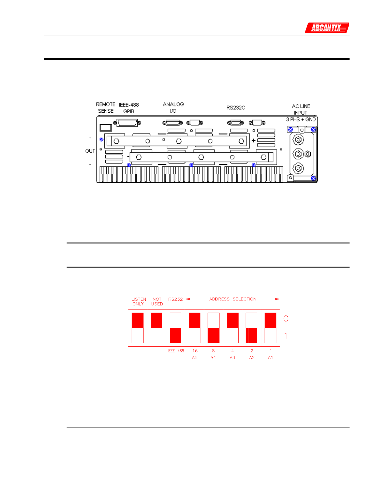
User and Programming Manual
9.4 Optional IEEE Interface
The XDS Series can optionally be equipped with an IEEE-488 interface in addition to the standard
RS232C interface.
Figure 9-2: Rear Panel View
The IEEE address of the XDS DC Supply is set using the DIP-switch at the right side of the unit.
(When facing power supply from the front). The switch is located on the controller board (A1) and
visible through the side air intake openings. Switch position 4 through 0 corresponds to bits 4
through 0 of the IEEE address. The desired interface is selected by moving DIP-switch position 5 to
the correct mode. Only one interface can be active at a time.
Note: Always turn off the power supply and disconnect AC input power when
changing this DIP setting. Use a non-metallic object to change switch
positions for the Address.
Figure 9-3: GPIB Address Selection Switch
The dark section represents the switches.
The above configuration would cause the unit to be in GPIB mode at address 10.
Listen only mode is not supported and this switch must be in the up position (Listen Only mode
OFF) to work properly.
Note: Switch setting changes do not take effect until power is cycled.
XDS Series 73
Page 74

User and Programming Manual
9.5 XDSGUI Installation
This section covers installation of the XDSGUI from the distribution disk to the user’s PC. Make sure
the PC is capable of running Windows.
9.5.1 Connecting to the PC Using RS232
Connect the power supply to the PC using an RS232C cable.
The power supply RS232C port settings are set as follows:
Baud rate: 19200 baud
Data bits: 8
Stop bits 1
Parity bits: none
Handshake: Hardware
The power supply source is configured to accept the above setting.
9.5.2 Connecting to the PC Using the optional IEEE-488/GPIB interface
Connect the power supply to the PC using an IEEE-488 interface cable. A National Instruments
GPIB controller card is required to use the XDSGUI program.
Make sure the IEEE-488 interface is selected by checking the DIP switch on the side of the unit. It
should be in the IEEE-488 position. (See section 9.4).
Set the desired IEEE address using DIP switch position 4 through 0 on the rear panel. (See section
9.4).
9.5.3 Installing the XDSGUI Software
The XDSGUI software is distributed on CD-ROM. The XDSGUI must be installed from CD using the
included setup program as all required files are compressed. To install the XDSGUI, proceed as
follows:
1. Turn on the PC and boot up in Windows™
2. Iinsert the CD in your CD-ROM drive.
3. Run the Setup.exe program from the root directory of the CD.
4. A CD Browser like program will open. Select the product series for which you want to
install the software and select the GUI Software tab. Select an available operating
system (typically 32 bit Windows) and click on the Install button to begin the installation.
5. Follow the instructions provided by the setup program to complete the installation.
6. When the installation has completed, remove the CD ROM and store in a safe place.
If prompted to do so, reboot the PC to activate the new settings. You are now ready to start using the
XDSGUI software.
74 XDS Series
Page 75

User and Programming Manual
9.6 Trouble Shooting - RS232C
This section provides guidelines for resolving communication problems that may occur when using
the XDSGUI software under Windows.
You may encounter problems when using the serial interface with the XDSGUI program that is
supplied with the interface option for this source.
Symptoms:
1. Unable to verify connection to the power supply through RS232C interface. Time-out occurs and
dialog box appears that asks if you want to switch to simulation mode. An error message (ERR -
100) may appear on the front panel LED’s of the power supply.
- Or -
2. Verification is successful but slewing of voltage or current limit results in an ERR -100.
Things to check first:
1. Is any PC com port available for communication with the power supply? On older PC’s com port
interrupts are often shared between com 1 and com3 as well as com2 and com 4. If any of these
other com ports is in use, it may prevent you from using the com port that shares the same
interrupt.
2. Did you use the RS232C cable that was supplied with the power supply? If not, make sure you
obtain the correct cable. (DB9 to DB9, straight through, male to female).
Resolution for Symptom 1
The XDS Series of power supplies require hardware handshaking to control data flow from the PC to
the Power supply. After receiving a command, the power supply asserts the DTR line to hold off
further communication from the PC until the command just sent has been processed. Under
Windows, it is possible to use a 16 byte transmit buffer if a 16550 UART is present. This FIFO
exceeds the length of most Power supply commands. When enabled, this mode may result in more
than one command being placed in the UART output buffer. If this happens, the handshake from the
Power supply will not prevent the content of this buffer being sent to the Power supply and thus will
result in more than one command being sent to the Power supply.
To resolve this problem, the UART FIFO length needs to be reduced or disabled altogether. The
procedure to disabled the FIFO mode is outlined in the next paragraph.
Note: If turning off the UART FIFO conflicts with other applications that need to run on the same PC
using the same COM port, this solution may not be acceptable. In this case, skip this step and
proceed to the second symptom resolution, which relies on a software implemented hold-off instead
of turning off the FIFO buffer.
XDS Series 75
Page 76

User and Programming Manual
Procedure
1. Make sure the XDSGUI program is closed and no device
is using the com port in use.
2. From the Windows desktop, right click on the “My
Computer” icon which is located in the top left corner of
the screen.
3. From the popup menu, select the “Properties” entry.
4. This brings up the System Properties dialog box
5. From the tabs shown at the top of the dialog box, select
the “Device Manager” tab.
6. The relevant screen is shown in Figure 9-4.
7. Expand the Ports(COM&LPT) tree selection by clicking
on the ‘+’ sign
8. Select the COM port you plan to use to communicate with
the P or XDS Series power supply.
9. With the correct COM port selected, click on the
Properties button at the bottom left of the dialog box.
10. This brings up the settings dialog box for the COM port.
In this example, COM2 is used.
11. From the tabs at the top of the dialog box, select the “Port
Settings” tab.
12. This should bring up the dialog shown in Figure 9-6.
13. Next, select the Advanced button to bring up the
advanced port settings dialog box shown in Figure 9-5.
Figure 9-4: System Properties Dialog Box
Figure 9-5: Advanced Port Settings Dialog Box
14. At the top of the dialog box, disable the “Use FIFO buffers
(requires 16550 compatible UART)” checkbox. This will
bypass the UART FIFO’s and enable the hardware
handshake to work correctly. If the FIFO cannot be
turned off, set the Receive buffer to max (14) and the
Transmit buffer to min. (1).
Figure 9-6: COM Port Properties Dialog Box
15. Click on the all OK buttons to close all dialog boxes that
remain open.
16. This should enable the XDSGUI to work correctly.
76 XDS Series
Page 77

User and Programming Manual
Resolution for Symptom 2
Execute the suggested procedure to resolve symptom 1 first. If an occasional error continues to
occur while slewing the voltage or frequency slider controls in the XDSGUI program, increase the
command delay paramter located in the System, Interface dialog. The default value for the CmdDelay
is set to 30 and is displayed below the command line of the Interface window. Change this value to
40 by entering the new value from the keyboard.
Try to connect again. You may have to cycle the power on the power supply if it still shows the Err 100 display.
Higher values than 40 may be set for the CmdDelay parameter if this fix does not resolve your
problem.
XDS Series 77
Page 78

User and Programming Manual
9.7 Trouble Shooting - IEEE-488 / GPIB
This section provides guidelines for resolving communication problems that may occur when using
the power supply with or without the XDSGUI software with a IEEE-488 / GPIB interface.
Symptoms:
1. Unable to verify connection to the power supply through IEEE-488 interface. Time-out occurs any
time an attempt is made to verify connection.
Things to check first:
1. Is the interface option set to use the IEEE-488 interface instead of the RS232C interface? The
DIP switch on the right side panel of the power supply is used to select the desired interface
mode. Refer to section 0. If the GPIB option (option -IF) was ordered, it should be set this way
from the factory but may have been changed after shipment).
2. Does the bus address selected in the System, Interface dialog match the address set using the
DIP switches on the power supply. The GPIB address selected must match the settings on the
DIP switch. If changes are made to the DIP switch setting, the power supply must be cycled off
and on to have the new settings take effect.
3. Did you connect the cable in correctly and are both ends of the GPIB cable securely tied down?
Resolution for Symptom 1
When using a fast IEEE-488 bus controller, the power supply's IEEE-488 interface may not
handshake fast enough to satisfy the controllers timing requirement. If this is the case, a time-out will
result any time a command is sent to the power supply. To rectify this situation, the IEEE-488
controller must be set to use delayed bus timing. For National Instruments GPIB controller cards
running under Windows™, this can be done from the device manager.
Select the GPIB interface and click on the NI-488.2M Settings tab. An Advanced button at the bottom
of the screen will provide access to the Bus Timing parameter. Try settng this value to 500 nsec or
2sec to operate with the power supply's
GPIB interface.
Figure 9-8: NI PCI-GPIB Advanced
Settings Dialog
Figure 9-7: NI PCI-GPIB Settings
Test Sequence Program Directory Files
78 XDS Series
Page 79

User and Programming Manual
9.8 Software Registration
Updates of this and other Argantix programs and drivers are posted on a regular basis on the
Argantix web site. You can find available programs by selecting the Software, GUI's and Drivers
menu. To gain access to these downloads, you will need to register as a user on our web site. For
instructions on how to register and request the required access level for software downloads, visit our
web site at
www.argantix.com
XDS Series 79
Page 80

User and Programming Manual
10 Introduction to SCPI
SCPI (Standard Commands for Programmable Instruments) is a programming language for
controlling instrument functions over the RS232 or IEEE 488 bus. The same SCPI commands and
parameters control the same functions in different classes of instruments. For example, you would
use the same MEAS:VOLT? command to measure the Power supply output voltage or the output
voltage of a SCPI-compatible Multimeter.
10.1 Conventions Used in This Manual
Angle brackets<> Items within angle brackets are parameter abbreviations. For example,
<NR1> indicates a specific form of numerical data.
Vertical bar Vertical bars separate alternative parameters. For example, 0 | 1 indicates
that either "0" or "1" can be used as a parameter.
Square Brackets[] Items within square brackets are optional. The representation
[SOURce:]VOLT means that SOURce: may be omitted.
Boldface font Boldface font is used to emphasize syntax in command definitions. CURR
<NRf> shows a command definition.
Upper case font Upper case font is used to show program lines in text. OUTP 1 shows a
program line.
10.2 The SCPI Commands and Messages
This paragraph explains the syntax difference between SCPI Commands and SCPI messages.
The power supply supports two types of commands, IEEE-488-2 common and SCPI subsystem
commands.
IEEE-488-2 common commands are generally not related to specific operations but to controlling
overall Power supply functions such as reset, status and synchronization. All common
commands consist of a three-letter mnemonic preceded by an asterisk:
*RST *IDN? *SRE 255
SCPI Subsystem commands perform specific Power supply functions. They are organized into
an inverted tree structure with the "root" at the top. Some are single commands while others are
grouped within specific subsystems. You must include the root header in all commands sent
to the Power supply.
Refer to appendix A for the SCPI tree structure.
Types of SCPI Messages
There are two types of SCPI messages, program and response.
A program message consists of one or more properly formatted SCPI commands sent from the
controller to the Power supply. The message, which may be sent at any time, requests the Power
supply to perform some action.
A response message consists of data in a specific SCPI format sent from the Power supply to the
controller. The Power supply sends the message only when commanded by a program message
called a "query."
80 XDS Series
Page 81

User and Programming Manual
The SCPI Command Tree
As previously explained, the basic SCPI communication method involves sending one or more
properly formatted commands from the SCPI command tree to the instrument as program messages.
The following figure shows a portion of a subsystem command tree, from which you access the
commands located along the various paths (you can see the complete tree in appendix A).
Root
[:SOURce] :VOLTage [:LEVel]
:CURRent :RANGe
:SYSTem :REMote
:ERRor
:LIMit :VOLTage :LOW?
:HIGH?
Figure 10-1: Partial Command Tree
The Root Level
Note the location of the ROOT node at the top of the tree. Commands at the root level are at the top
level of the command tree. The SCPI interface is at this location when:
The Power supply is powered on
A device clear (DCL) is sent to the Power supply
The SCPI interface encounters a message terminator
The SCPI interface encounters a root specifier
Active Header Path
In order to properly traverse the command tree, you must understand the concept of the active
header path. When the Power supply is turned on (or under any of the other conditions listed above),
the active path is at the root. That means the SCPI interface is ready to accept any command at the
root level, such as SOURCe or MEASurement.
If you enter SOURCe the active header path moves one colon to the right. The interface is now ready
to accept :VOLTage or :CURRent as the next header. You must include the colon, because it is
required between headers.
Note: The XDS Series interface buffer is limited to 21 characters, however. As such, compound
commands are not recommended as they often exceed this message length limit.
XDS Series 81
Page 82

User and Programming Manual
Moving Among Subsystems
In order to combine commands from different subsystems, you need to be able to restore the active
path to the root. You do this with the root specifier (:). For example, you could set the output voltage
to 60 V and set the display mode to power.
VOLT 60
DISP:MODE 3
Because the root specifier resets the command parser to the root, you can use the root specifier and
do the same thing in one message:
VOLT 60;:DISP:MODE 3
Including Common Commands
You can combine common commands with system commands in the same message. Treat the
common command as a message unit by separating it with a semicolon (the message unit
separator). Common commands do not affect the active header path; you may insert them anywhere
in the message.
VOLTage 115;*ESE 255
OUTPut 0;*RCL 2
82 XDS Series
Page 83

User and Programming Manual
10.3 Using Queries
Observe the following precautions with queries:
Set up the proper number of variables for the returned data.
Read back all the results of a query before sending another command to the power supply .
Otherwise a Query Error will occur and the non-returned data will be lost.
10.4 Structure of a SCPI Message
SCPI messages consist of one or more message units ending in a message terminator. The
terminator is not part of the syntax, but implicit in the way your programming language indicates the
end of a line (such as a newline or end-of-line character).
The Message Unit
The simplest SCPI command is a single message unit consisting of a command header (or keyword)
followed by a message terminator.
CURRent?<newline>
VOLTage?<newline>
The message unit may include a parameter after the header. The parameter usually is numeric:
VOLTage 20<newline>
OUTPut 1<newline>
Combining Message Units
The following command message is briefly described here, with details in subsequent paragraphs.
Data Query Indicator
Message Unit
Header
SOUR:VOLT 80; CURR 60; :CURR? <NL>
Header Message Root Message
Separator Unit Specifier Terminator
Separator
Figure 10-2: Command Message Structure
The basic parts of the above message are:
Message Component Example
Headers SOURC VOLT CURR CURR
Header Separator The colon in SOUR:VOLT
Data 80 60
Data Separator The space in VOLT 80 and CURR 60
Message Units VOLT 80 CURR 60 CURR?
Message Unit Separator The semicolons in VOLT 80; and CURR 60;
Root Specifier The colon in :CURR?
XDS Series 83
Page 84

User and Programming Manual
Query Indicator The question mark in CURR?
Message Terminator The <NL> (newline) indicator. Terminators are not part of the SCPI
syntax
Note: The use of compound messages such as the one shown in Figure 12-2 is not
recommended as they typically exceed the available receive buffer length of
the XDS Series interface.
Headers
Headers are instructions recognized by the power source. Headers (which are sometimes known as
"keywords") may be either in the long form or the short form.
Long Form The header is completely spelled out, such as VOLTAGE, SYSTEM, and OUTPUT.
The XDS Parser will stop parsing the remainder of any command after its short form
has been parsed. Effectively, this means the remainder will be a don't care and
syntax errors will not be detected or reported.
Short Form The header has only the first three or four letters, such as VOLT, SYST, and OUTP.
The XDS parser only parses the short form of all SCPI commands and ignores any
remainder.
The SCPI interface is not sensitive to case. It will recognize any case mixture, such as VOLTAGE,
VOLTage or Voltage. Short form headers result in faster program execution.
Note: In view of the 21 character receive buffer size of the XDS Series, the short form
is recommended under all circumstances.
Header Convention
In the command descriptions used in this manual, the proper short form is shown in upper-case
letters, such as DELay.
Header Separator
If a command has more than one header, you must separate them with a colon, e.g.
(SYSTem:ERRor LIMit:VOLT:LOW).
Optional Headers
The use of some headers is optional. Optional headers are shown in brackets, such as
VOLTage[:LEVel] 100.
Query Indicator
Following a header with a question mark turns it into a query (VOLTage?).
Message Unit Separator
When two or more message units are combined into a compound message, separate the units with a
semicolon (VOLT 100;CURR 60).
Root Specifier
When it precedes the first header of a message unit, the colon becomes the root specifier. It tells the
command parser that this is the root or the top node of the command tree. Note the difference
between root specifiers and header separators in the following examples:
SOURce:VOLTage:LEVel 100 All colons are header separators
:SOURce:VOLTage:LEVel 100 Only the first colon is a root specifier
SOURce:VOLTage:LEVel 100;:CURRent 55 Only the third colon is a root specifier
You do not have to precede root-level commands with a colon; there is an implied colon in front of
every root-level command.
84 XDS Series
Page 85

User and Programming Manual
Message Terminator
A terminator informs SCPI that it has reached the end of a message. The only permitted message
terminator is:
newline (<NL>), which is ASCII decimal 10 or hex 0A.
In the examples of this manual, there is an assumed message terminator at the end of each
message. If the terminator needs to be shown, it is indicated as <NL> regardless of the actual
terminator character.
10.5 SCPI Data Formats
All data programmed to or returned from the power source is in ASCII. The data type may be
numerical or character string.
Numerical Data Formats
Symbol Data Form
Talking Formats
<NR1> Digits with an implied decimal point assumed at the right of the least-significant digit.
Examples: 273
<NR2> Digits with an explicit decimal point. Example:.0273
<NR3> Digits with an explicit decimal point and an exponent. Example: 2.73E+2
<Bool> Boolean Data. Example: 0 | 1
Listening Formats
<Nrf> Extended format that includes <NR1>, <NR2> and <NR3>. Examples: 273.2 ,
2.73E2
<Bool> Boolean Data. Example: 0 | 1
Character Data
Character strings returned by query statements may take either of the following forms, depending on
the length of the returned string:
<CRD> Character Response Data. Permits the return of character strings.
<AARD> Arbitrary ASCII Response Data. Permits the return of undelimited 7-bit ASCII. This
data type has an implied message terminator.
<SRD> String Response Data. Returns string parameters enclosed in double quotes.
XDS Series 85
Page 86

User and Programming Manual
10.6 Programming Tips
When developing custom application code, the following guidelines should be followed if possible:
All commands should be terminated with <NL> (hex 0A) character. In "C", the \n character sequence
will result in a <NL> character. This is the message terminator.
The receive buffer of the XDS is limited to about 21 characters. Avoid sending long compound
message strings consisting of multiple commands. Commands longer than the receive buffer will
result in "-100, Syntax Error"
Successive non-query commands (e.g. VOLT 100) sent to the unit should be spaced at least 20
msec apart. This is to allow the interface of the unit to receive and transmit the command over it's
internal optically isolated serial bus to the main processor. This process takes place for both GPIB
and RS232C control so this 'command hold-off' delay period is needed regardless of which interface
is used. The same delay is not required following a query command (e.g. VOLT?) as the application
program generally waits for the response before sending the next command.
Inserting this delay does not affect real through put as the unit would not respond any faster if
commends were sent consecutively without delays in between.
Some commands take extra time to execute as they update the non-volatile memory of the unit. In
particular, the *SAV command requires 300 msec to complete. No commands should be send during
this time period.
It is good practice to check for error messages using the *ESR? or SYST:ERR? Queries. The XDS
does not generate an SRQ on the GPIB bus so programmed polling is needed to check for status or
errors.
86 XDS Series
Page 87

User and Programming Manual
11 SCPI Command Reference
Where appropriate, related commands or queries are included. These are listed because they are
either directly related by function, or because reading about them will clarify or enhance your
understanding of the original command or query.
This chapter is organized as follows:
Subsystem commands, arranged by subsystem
IEEE 488.2 common commands
11.1 Subsystem Commands
Subsystem commands are specific to Power supply functions. They can be a single command or a
group of commands. The groups are comprised of commands that extend one or more levels below
the root. The description of common commands follows the description of the subsystem commands.
The subsystem command groups are listed in alphabetical order and the commands within each
subsystem are grouped alphabetically under the subsystem. Commands followed by a question mark
(?) take only the query form. When commands take both the command and query form, this is noted
in the syntax descriptions.
XDS Series 87
Page 88
User and Programming Manual
11.2 Measurement Subsystem
This subsystem programs the measurement capability of the power supply.
Subsystem Syntax
MEASure
:CURRent?
[:LEVel] Returns the average DC value of current
:AMPLitude
:MAX? Returns peak current measurement reading
:RESet Resets the peak current measurements
:POWer Returns the DC power measurement reading.
:VOLTage? Returns the DC voltage measurement reading
MEASure:CURRent[:LEVel]?
This query returns the DC value of the DC current being sourced at the output terminals. Note that
the output must be on to obtain current flow.
Query Syntax MEASure:CURRent?
Parameters None
Examples MEAS:CURR?
Returned Parameters <NR2>
Related Commands OUTP 0 1 MEAS:CURR:AMPL:MAX?
MEASure:CURRent:AMPLitude:MAX?
This query returns the peak current value of the output current being sourced at the output terminals.
Note that the output must be ON to obtain current flow. The peak current measurement circuit uses a
sample and hold method and latches the highest peak current value found since the last peak
measurement reset command.
Query Syntax MEASure:CURRent:AMPLitude:MAX?
Parameters None
Examples MEAS:CURR:AMPL:MAX?
Returned Parameters <NR2>
Related Commands OUTP 0 1 MEAS:CURR?
MEASure:CURRent:AMPLitdue:RESet
This command resets the peak current measurement sample and hold circuit to zero.
Query Syntax MEASure:CURRent:AMPLitude:RESet
Parameters None
Examples MEAS:CURR:AMPL:RES
Related Commands MEAS:CURR:AMPL:MAX?
88 XDS Series
Page 89

User and Programming Manual
MEASure:POWer?
This query returns the DC power delivered to the unit under test by the Power supply. Note that the
output must be on to obtain current flow.
Query Syntax MEASure:POWer?
Parameters None
Examples MEAS:POW?
Returned Parameters <NR2>
Related Commands MEAS:VOLT? MEAS:CURR?
MEASure:VOLTage?
This query returns the average DC voltage being sourced at the output terminals. Note that the
output must be on or no voltage will be present at the output terminals.
Query Syntax MEASure:VOLTage?
Parameters None
Examples MEAS:VOLT?
Returned Parameters <NR2>
Related Commands OUTP 0 1
XDS Series 89
Page 90

User and Programming Manual
11.3 Source Subsystem
This subsystem programs all the output parameters of the power supply.
Subsystem Syntax
[SOURce:]
CURRent:
[LEVel] Set the current value in amps.
HIGH Set the maximum current allowed
LOW Set the minimum current allowed
LIMit:
CURRent? Current range limt: Model specific
VOLTage? Voltage range limit. Model specific
MODE? Returns power supply operating mode.
VOLTage:
[LEVel] Set the output voltage value in volts.
HIGH Set the maximum voltage allowed
LOW Set the minimum voltage allowed
PROTection
[:LEVel] Set the over voltage protection trip level in % of
range.
STATe Enables or disabels OVP mode.
[SOURce:]CURRent[:LEVel]
This command sets the current limit of the output. If the load current exceeds the programmed
current limit, the power supply will cross over from voltage mode to current mode. In this mode, the
output voltage will fold back as much as needed to retain the current at the programmed limit.
The current may be set between the low limit and high limit as programmed using the CURR:HIGH
and CURR:LOW commands. However, the high limit cannot be higher than the model's capability
(configuration limit) which can be queried with the LIM:CURR? command. The low limit cannot be
less than zero. The *RST state for high and low current is zero for low, and maximum configuration
limit for high. (model specific).
Command Syntax [SOURce:]CURRent <NRf>
Parameters value between CURR:HIGH and CURR:LOW settings.
Unit A (amperes)
*RST Defined by the PON
Examples CURR 5
Query Syntax CURRent?
Returned Parameters <NR2>
Related Commands CURR:HIGH CURR:LOW
[SOURce:]CURRent:HIGH
This command sets the maximum programmed current that will be accepted by the power supply. If a
value above this limit value is programmed, a "-200 Execution Error" will be generated.
The current limit may be set between zero and the model's capability (configuration limit) which can
be queried with the LIM:CURR? command. The high limit cannot be less than the low limit however.
The *RST state for high current limit is the maximum configuration limit. (model specific).
90 XDS Series
Page 91

User and Programming Manual
Command Syntax [SOURce:]CURRent:HIGH <NRf>
Parameters 0 to LIM:CURR? value.
Unit A (amperes)
*RST Max. Current
Examples CURR:HIGH 5
Query Syntax CURRent:HIGH?
Returned Parameters <NR2>
Related Commands CURR CURR:LOW
[SOURce:]CURRent:LOW
This command sets the minimum programmed current that will be accepted by the power supply. If a
value below this limit value is programmed, a "-200 Execution Error" will be generated.
The current limit may be set between zero and the model's capability (configuration limit) which can
be queried with the LIM:CURR? command. The low limit cannot be more than the high limit however.
The *RST state for low current limit is zero.
Command Syntax [SOURce:]CURRent:LOW <NRf>
Parameters 0 to LIM:CURR? value.
Unit A (amperes)
*RST 0
Examples CURR:LOW 5
Query Syntax CURRent:LOW?
Returned Parameters <NR2>
Related Commands CURR CURR:HIGH
[SOURce:]LIMit:CURRent?
This command queries the maximum current the power supply can deliver. Only the Query format of
this command is available to the user.
Command Syntax [SOURce:]LIMit:CURRent <NRf>
Parameters maximum current [command protected]
Query Syntax LIMit:CURRent?
Returned Parameters <NR2>
[SOURce:]LIMit:VOLTage?
This command queries the maximum voltage the power supply can deliver. Only the Query format of
this command is available to the user.
Command Syntax [SOURce:]LIMit:VOLTage<NRf>
Parameters maximum voltage [command protected]
Query Syntax LIMit:VOLTage?
Returned Parameters <NR2>
XDS Series 91
Page 92

User and Programming Manual
[SOURce:]MODE
This command is used to query the power supply's operating mode. The power supply can operate
in either Constant Voltage or Constant Current mode. A numeric value is returned for a MODE?
Query and is encoded as shown in the table below:
Value Mode
0 Undefined.
1 Constant Voltage (CV)
2 Constant Current (CC)
3 Cross over CV and CC mode
Table 11-1: Mode query result decoding
Command Syntax [SOURce:]MODE?
Parameters None
Query Syntax MODE?
Returned Parameters <NR1>
Related Commands none
[SOURce:]VOLTage[:LEVel]
This command programs the DC output voltage level of the power supply.
The voltage may be set between the low limit and high limit as programmed using the VOLT:HIGH
and VOLT:LOW commands. However, the high limit cannot be higher than the model's capability
(configuration limit) which can be queried with the LIM:VOLT? command. The low limit cannot be
less than zero. The *RST state for high and low voltage is zero for low, and maximum configuration
limit voltage for high. (model specific).
Command Syntax [SOURce:]VOLTage[:LEVel] <NRf>
Parameters value between VOLT:HIGH and VOLT:LOW settings.
Unit V (rms voltage)
*RST Value 0 volt
Examples VOLT 250 VOLT:LEV 25
Query Syntax [SOURce:]VOLTage[:LEVel]?
Returned Parameters <NR2>
Related Commands VOLT:HIGH VOLT:LOW
92 XDS Series
Page 93

User and Programming Manual
[SOURce:]VOLTage:HIGH
This command sets the maximum programmed voltage that will be accepted by the power supply. If a
value above this limit value is programmed, a "-200 Execution Error" will be generated.
The voltage limit may be set between zero and the model's capability (configuration limit) which can
be queried with the LIM:VOLT? command. The high limit cannot be less than the low limit however.
The *RST state for high voltage limit is the maximum configuration limit. (model specific).
Command Syntax [SOURce:]VOLTage:HIGH <NRf>
Parameters 0 to LIM:VOLT? value.
Unit V (Volt)
*RST Max. Voltage
Examples VOLT:HIGH 5
Query Syntax VOLTage:HIGH?
Returned Parameters <NR2>
Related Commands VOLT VOLT:LOW
[SOURce:]VOLTage:LOW
This command sets the minimum programmed current that will be accepted by the power supply. If a
value below this limit value is programmed, a "-200 Execution Error" will be generated.
The voltage limit may be set between zero and the model's capability (configuration limit) which can
be queried with the LIM:VOLT? command. The low limit cannot be more than the high limit however.
The *RST state for low current limit is zero.
Note: This feature is best reserved for program control applications. If a low voltage limit is set over
the bus and the unit is subsequently used stand-alone from the front panel, it is possible that the
voltage is set to 0 volt as a result of a fault condition. If this happens, the front panel voltage knob will
be locked out from that point forward and the operator will be enable to remedy this lock-out as the
volt low limit cannot be set from the front panel. To avoid these potential lock-outs, leave the volt low
limit at 0 Volts.
Command Syntax [SOURce:]VOLTage:LOW <NRf>
Parameters 0 to LIM:VOLT? value.
Unit V (Voltage)
*RST 0
Examples VOLT:LOW 5
Query Syntax VOLTage:LOW?
Returned Parameters <NR2>
Related Commands VOLT VOLT:HIGH
XDS Series 93
Page 94

User and Programming Manual
[SOURce:]VOLTage:PROTection[:LEVel]
This command programs the OVP trip level of the power supply.
The OVP trip level is set as a percentage of voltage range. Allowable range is 0 to 110%. If the
output voltage exceeds the set trip level and the OVP mode is enabled, the power supply will
generate a -300, Device specific error and turn off the output. The mode is enabled with the
VOLT:PROT:STAT command. The OVP mode provides another level of protection in addition to the
volt:high user setting which prevents programming commands or front panel inputs above this level
to be accepted. The OVP function is based on the measured output voltage rather than the
programmed output value.
Command Syntax [SOURce:]VOLTage:PROTection[:LEVel] <NR1>
Parameters percentage of V range
Unit %
*RST Value 110
Examples VOLT:PROT 80 VOLT:PROT:LEV 25
Query Syntax [SOURce:]VOLTage:PROTection[:LEVel]?
Returned Parameters <NR1>
Related Commands VOLT:PROT:STATE
[SOURce:]VOLTage:PROTection:STATe
This command enables or disables the OVP mode of the power supply.
The OVP mode state may be set using this command. If the output voltage exceeds the set trip level
and the OVP mode is enabled, the power supply will generate a -300, Device specific error and turn
off the output. If the OVP mode is disabled, nothing will happen. Valid parameters are 0 for OVP off
and 1 for OVP on.
Command Syntax [SOURce:]VOLTage:PROTection:STATe <NR1>
Parameters 0 | 1
*RST Value 0
Examples VOLT:PROT STAT 0 VOLT:PROT:STAT 1
Query Syntax [SOURce:]VOLT:PROT:STAT?
Returned Parameters <NR1>
Related Commands VOLT:PROT[:LEV]
94 XDS Series
Page 95

User and Programming Manual
11.4 Output Subsystem
This subsystem controls the output of the power supply.
Subsystem Syntax
OUTPut
[:RELay] Turns the output on or off.
DROP
[:TIME] Sets the output voltage for a specified amount of time or indefinitely to the
voltage level set.
:LEVel Sets the absolute voltage level to 'drop' to.
OUTPut[:RELay]
The output of the Power supply can be turned on (1) or off (0) using this command. The status of the
output relay can be queried as well. Note that if the output is shut-down by the remote shut-down
input signal on connector J22, the output query only returns the programmed state, not the actual
state of the output. Thus, the remote shut-down (remote inhibit) overrides the programmed state of
the output.
Command Syntax OUTPut[:RELay] <bool>
Parameters <Bool> 0 | 1
*RST Value defined by the PONS
Examples OUTP 1
Query Syntax OUTPut?
Returned Parameters 0 | 1
Related Commands OUTP:DROP OUTP:LEV
OUTPut:DROP[:TIME]
The output drop command may be used to change the voltage to the UUT for a specific period of
time. This command may be used to change the output voltage for a period of time as little as 1
msec or as long as 4000 sec. The voltage setting during this time is determined by the
OUTP:DROP:LEV command.
The parameter passed with the OUTP:DROP command is the event duration in seconds. This value
can range from 0.001 (1 msec) to 4000 (1 hour, 6 min, 40 sec) but only four digits of resolution are
allowed. If no parameter is passed, the output is set to the programmed drop level indefinitely or until
a voltage command is issued. Thus valid time periods are:
Time range Range
0.001 - 9.999 1 msec to 10 secs
10.00 - 99.99 10 secs to 100 secs
100.0 - 999.9 100 secs to 1000 secs
1000 - 4000 1000 secs to 4000 secs
no parameter Infinite time. Use VOLT command to turn output on.
Output drop status query
The status of a drop in progress can be queried using the query format of the OUTP:DROP
command. This query will return a <Bool> indicating if the output time specified has expired (0) or
the drop is still in progress (1).
XDS Series 95
Page 96

User and Programming Manual
Command Syntax OUTPut:DROP <NRf>
Parameters <NRf> | none
*RST Value none
Examples OUTP:DROP 0.001
Query Syntax OUTP:DROP?
Returned Parameters 0 | 1
Related Commands OUTP:DROP:LEV
OUTPut:DROP:LEVel
The output drop level command sets the voltage level used by the OUTP:DROP:TIME command.
The level set must be between the VOLT:HIGH and VOLT:LOW limits or a "-200, Execution Error"
will be generated.
Command Syntax OUTPut:DROP:LEVel <NRf>
Parameters <NRf>
*RST Value 0
Examples OUTP:DROP:LEV 20.5
Query Syntax OUTP:DROP:LEV?
Returned Parameters <NR2>
Related Commands OUTP:DROP
96 XDS Series
Page 97

User and Programming Manual
11.5 Display Subsystem
DISPlay:MODE
This command is used to control the right hand side Power supply LED display. The command will
allow the multifunction LED display to switch between display of:
1. current setting or current measurement,
2. peak current measurement
3. power measurement.
The encoding for the mode command is as shown in the table below,
Parameter Value
Current 1
Peak Current 2
Power 3
Table 11-2: Display Mode Command Encoding
Command Syntax DISPlay:MODE <NR2>
Parameters 1 | 2 | 3
*RST Value 1
Examples DISP:MODE 2
Query Syntax DISPlay:MODE?
Returned Parameters <NR1>
Related Commands none
XDS Series 97
Page 98

User and Programming Manual
11.6 System Commands
The system commands control the system level functions of the Power supply.
Subsystem Syntax
SYSTem:
CONFigure Sets the Remote Inhibit (RI) polarity mode
ERRor? Returns the error number and error string
KLOCk Keyboard Lock. Sets the power on REMOTE/LOCAL state.
LOCal Go to local mode
PON Define the power on register number
REMote Go to remote mode
SYSTem:CONFigure
This commands set the polarity mode for the Remote Inhibit shutdown input. Once set using the
SYST:CONF command, the mode can be retained at power up by sending the SYST:SAVE
command. Factory setting is 0 or active low. In this mode, the output will be disabled when the RI is
pulled to ground or shorted. When set to 1, the output will be enabled when the RI is pulled to ground
or shorted.
Note: This function is only supported on DC supplies with firmware revision 0.4 or higher. See *IDN?
for firmware revision.
Query Syntax SYSTem:CONFigure
Parameters 0 | 1
Returned Parameters <NR1>,<SRD>
Example SYST:CONF 0, followed by SYST:SAVE
SYSTem:ERRor?
This query returns the next error number followed by its corresponding error message string from the
remote programming error queue. The queue is a FIFO (first-in, first-out) buffer that stores errors as
they occur. As it is read, each error is removed from the queue. When all errors have been read, the
query returns 0,”No Error”. If more errors are accumulated than the queue can hold, the last error in
the queue is -350,”Queue overflow”.
Query Syntax SYSTem:ERRor?
Parameters None
Returned Parameters <NR1>,<SRD>
Example SYST:ERR?
SYSTem:KLOCk
This command sets or clears the power on LOCAL or REMOTE state. When set (1), the Power
supply will power up in remote state, locking out all keyboard controls. The local state can only be
entered by sending a bus command. This mode may be used to prevent operator access to front
panel controls under all conditions. Note that changing the state of the KLOC setting does not
change the REMOTE or LOCAL state. This setting only affects the REMOTE/LOCAL state at powerup.
Command Syntax SYSTem:KLOCk
Parameters 0 | 1
Example SYST:KLOC 1
Query Syntax SYST:KLOC?
Returned Parameters <NR1>
Related Commands SYST:REM SYST:LOC
98 XDS Series
Page 99

User and Programming Manual
SYSTem:LOCal
This command sets the interface in Local state, which enables the front panel controls. This
command only applies to the RS232C interface. If IEEE 488 is used, the remote/local state is
determined by the REN line on the IEEE 488 interface but the SYST:LOC and SYST:REM command
will also be accepted and will toggle the remote state despite the status of the IEEE REN line.
Command Syntax SYSTem:LOCal
Parameters None
Example SYST:LOC
Related Commands SYST:REM
SYSTem:REMote
This command sets the interface in the Remote state, which disables all front panel controls. This
command only applies to the RS232C interface. If IEEE 488 is used, the remote/local status is
determined by the REN line on the IEEE 488 interface but the SYST:LOC and SYST:REM command
will also be accepted and will toggle the remote state despite the status of the IEEE REN line.
Command Syntax SYSTem:REMote
Parameters None
Example SYST:REM
Related Commands SYST:LOC
SYSTem:PON
This command is used to define the register value the power supply will use to initialize its
parameters at power up. If data in the selected register is not valid or the selected register is 8, the
initialization will be with factory default values. Refer to Table 4-1: Factory Default Power on Settings
on page 33.
Command Syntax SYSTem:PON <NRf>
Parameters 0 to 8
Examples SYST:PON 1
Query Syntax SYST:PON?
Returned Parameters <NR1>
Related Commands *RST
XDS Series 99
Page 100

User and Programming Manual
11.7 Common Commands
Common commands begin with an * and consist of three letters (command) or three letters and a ?
(query). Common commands are defined by the IEEE 488.2 standard to perform some common
interface functions. The power supply responds to the required common commands that control
status reporting, synchronization, and internal operations. XDS Series units also respond to optional
common commands that control stored operating parameters.
Common commands and queries are listed alphabetically. If a command has a corresponding query
that simply returns the data or status specified by the command, then both command and query are
included under the explanation for the command. If a query does not have a corresponding command
or is functionally different from the command, then the query is listed separately. The description for
each common command or query specifies any status registers affected. Refer to Chapter 13 which
explains how to read specific register bits and use the information that they return.
Common Commands Syntax
*CLS Clear status
*ESE <n> Standard event status enable
*ESE? Return standard event status enable
*ESR? Return event status register
*IDN? Return instrument identification
*RCL <n> Recall instrument state
*RST Reset
*SAV <n> Save instrument state
*SRE <n> Set service request enable register
*SRE? Return service request enable register
*STB? Return status byte
100 XDS Series
 Loading...