

Page 1
www.hl-yeah.com
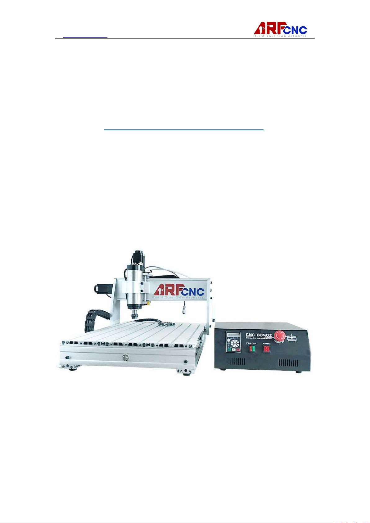
ARF CNC Router 6040
User Manual
Version 2.3
1 / 20
Page 2

www.hl-yeah.com
Table of Contents
Chapter 1 Introduction to CNC Systems
Before You Begin.......................................................................................................... 3
Chapter 2 Machine Connections ................................................................ 4
Chapter 3 Installing Mach3 Software
3.1.1 Mach3 Installing.............................................................................................. 5
3.2.1 XHC USB Motion Controller Driver v2.38.8 ......................................... ....... 7
3.3.1Mach3 Profile Creation................. ...... ....................... .................................... 8
Chapter 4 Machine Settings
4.1.1 Ports&Pins ................................................................. ............................. 9
4.2.1 Motor Tuning............................................................. ............................. 12
4.3.1 Motor home/Softlimits Setting ........................... ............. ...................... 13
4.4.1 Probe Setting ................................................ .......................... ............... 14
Chapter 5 Sample Engraving
Chapter 6 Trouble Shooting ................................................ ................. 18
APPENDIX ................................................ ................. ................. ...19
Video link: https://hl-yeah.com/2017/08/03/chinese-benchtop-commercial-cnc-woodrouter-setup/
2 / 20
Page 3
www.hl-yeah.com
Chapter 1 Introduction to CNC
Systems
This chapter introduces you to terminology used in the rest of this manual and
explains the purpose of the different components in a computer numerically
controlled (CNC) system. CNC machines are in many industries and becoming more
popular in manufacturing lines. The traditional machine types are Mills, Routers,
Lathes and Plasma cutters. The non traditional things that can be done with a CNC
system can be but not limited it laser measurement, pick and place, quilting,
assembly, laser cutting, rapid prototype, painting and so on.
Any machine tool is potentially dangerous. Computer controlled machines are
potentially more dangerous than manual ones because, for example, a computer is
quite prepared to rotate an 8" unbalanced cast iron four-jaw chuck at 3000 rpm, to
plunge a panel-fielding router cutter deep into a piece of oak, or to mill away the
clamps holding your work to the table.
If you are in any doubt, be sure to seek guidance from a professionally
qualified expert rather than risk injury to yourself or to others.
IP related to the software: the machine does not come with any software, operation
and use of this guide involved in the relevant software are from the Internet. All
copyrights belong to author, please go to the author's official website to download
the trial version or purchase authorization software. Any misuse of unauthorized
software, corresponding losses and legal issues are beared by the user.
When use desktop parallel port to connect CNC machine tool, you have to make sure
it was working at EPP mode. It can be setup in computer BIOS(refer to manufacturer
manual). Any after market available USB to the parallel port adapter can not make
the normal operation of the machine.
CNC engraving machine is to rely on the relevant software control work, the need for
proper software settings to normal operation. Without correct setting, machine
running can cause permanent damage.
Case 1, before Mach3 installment, Case 2, any sockets plug or disconnection, please
switch off control box. Machine tool work at 220V voltage, you must NOT open
housing in situation of power on.
During Machine Running, pleas wear Goggle and safety staffs to keep you safe.
3 / 20
Page 4
www.hl-yeah.com
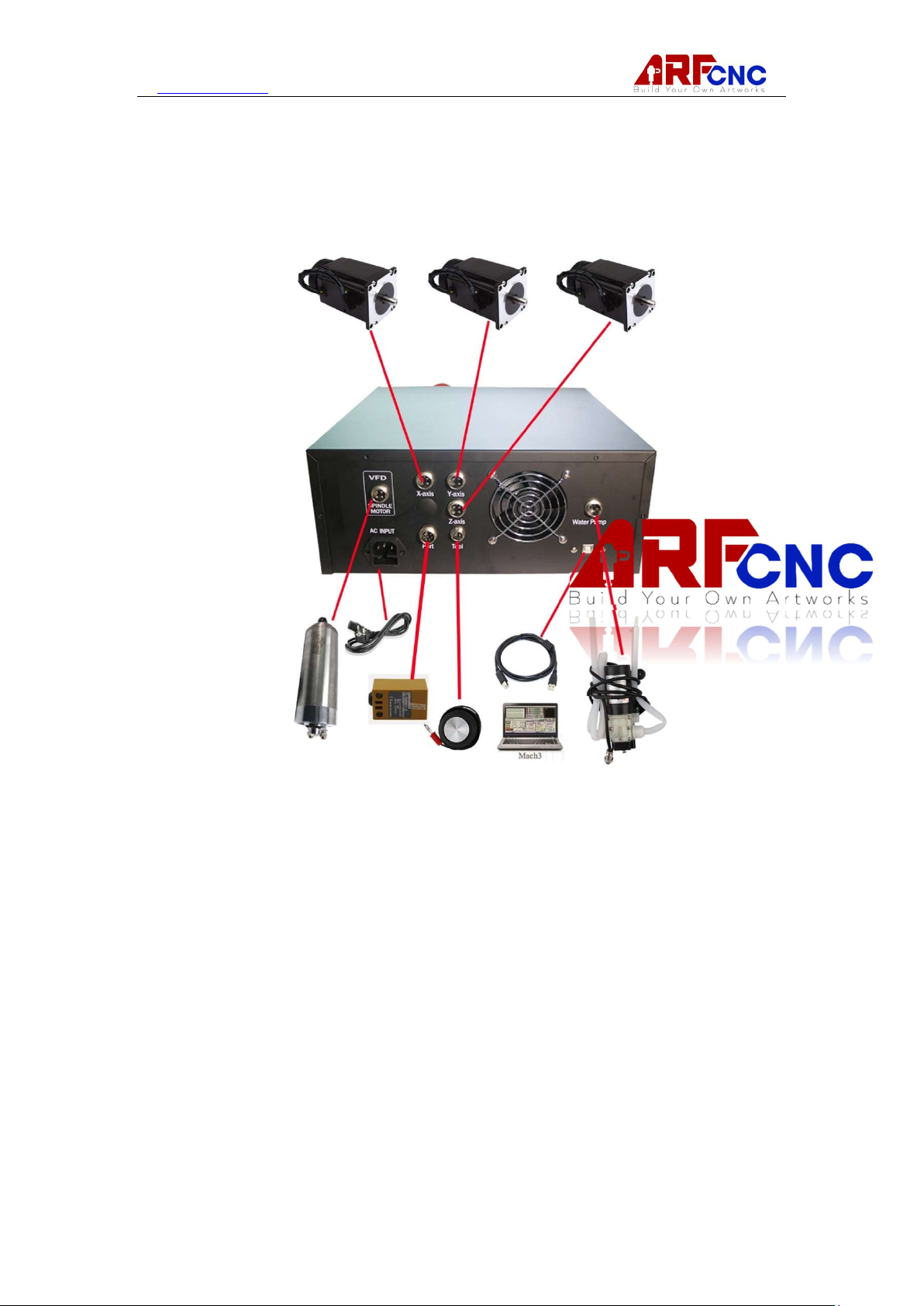
Chapter 2 Machine Connections
Mach3 Minimum Recommended Requirements:
XHC USB motion controller
Desktop or Laptop with Windows 2000, Windows XP, Windows Vista,
Windows 7, or Windows 8
1Ghz CPU
512MB RAM
Video Card with 32MB RAM
a video card with 512MB RAM or higher)
(Large G-code files, especially 3D files will require
4 / 20
Page 5

www.hl-yeah.com
Chapter 3 Installing Mach3 Software
And XHC USB Motion Controller
Mach3 is distributed by ArtSoft USA over the Internet. You download the package as
one self installing file. When installed, it will run for an unlimited period as a
demonstration version. As demonstration software, it places a few limitations on the
speed, the size of job that can be undertaken, and the specialist features supported.
When you purchase a licence, you can “unlock” the demonstration version you have
already installed and configured to give full software functionality. Details of pricing
and options are available at www.machsupport.com.
3.1.1 Downloading Download the installation package from www.machsupport.com.
Use the right mouse button and Save Target as… to put the self-installing file on the
Desktop or in a convenient folder. You should be logged in to Windows as an
Administrator. When the file has downloaded, it can be run immediately by using the
Open button on the download dialog window, or the download dialog window can be
closed and the installation done later. When you want to do the installation, run the
file you downloaded and saved. For example, if you saved the installation file on the
Desktop, just double-click it. If you saved the file in a folder, run Windows Explorer
(right click Start button), and double-click on the name of the downloaded file in the
folder.
3.1.2 Installing This section will guide you through the installation of the Mach3
software. If you already have a version of Mach3 installed on the computer, you can
install the new version on top of it. You do not need to remove the old version first.
3.1.2.1 If a machine tool is connected, disconnect it now. You do not need a
machine tool connected to install the software. In fact, if you are just starting it is
probably better not to have one connected. If a machine tool is connected to your
computer, note where the cable or cables from the machine tool are plugged into
your PC. Turn off the PC, the machine tool, and its drives, and unplug the cable
connector(s) from the back of the PC. Now switch the PC back on.
3.1.2.2 Run the Mach3 software installation package. When you run the downloaded
file, you will be guided through the usual installation steps for a Windows program
such as accepting the license conditions and selecting the folder for Mach3. ArtSoft
USA recommends that you allow Mach3 to use its default installation folder C:\Mach3.
The background image during installation is the standard Mach3Mill screen – do not
worry if you are planning to control a lathe, as Mach3Turn is also being installed. You
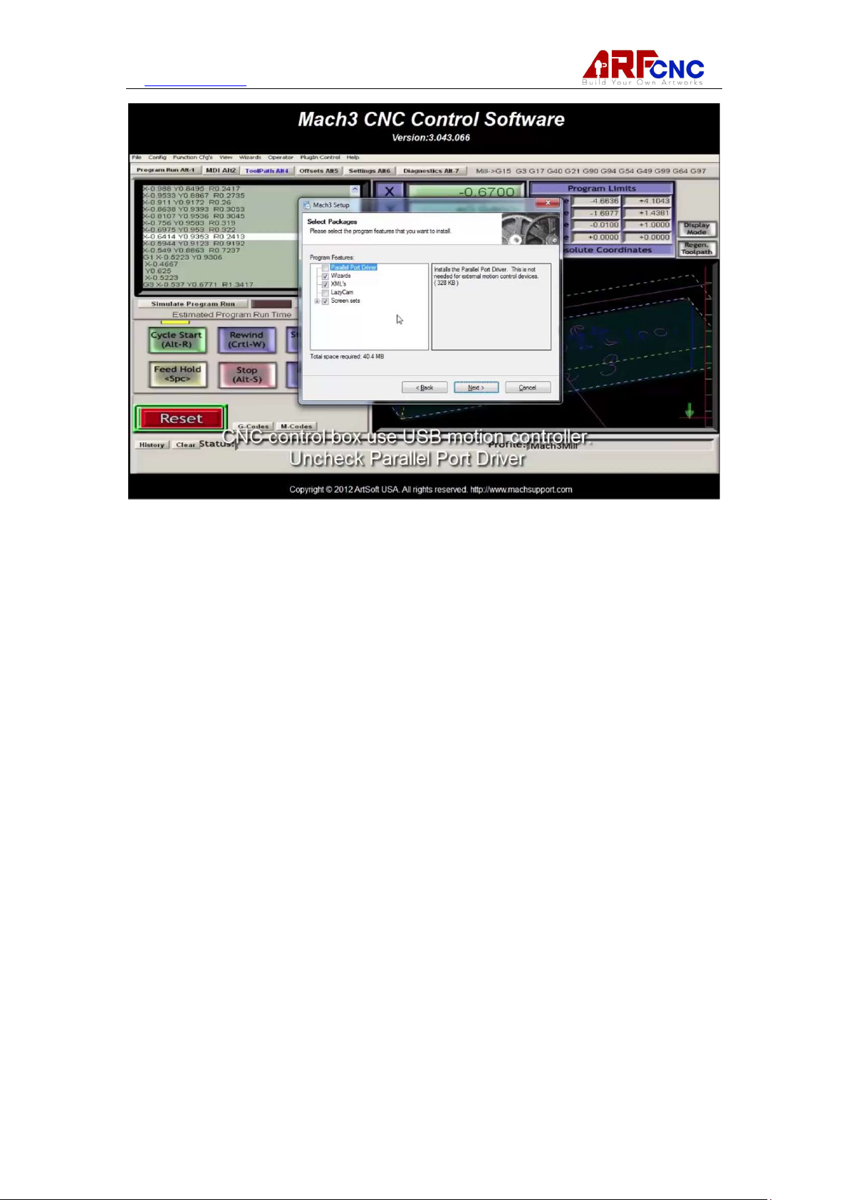
will be asked if you want to install various program components, as shown in Figure
3-1:
5 / 20
Page 6
www.hl-yeah.com
Because this control box use 4th generation XHC USB Motion Controller, uncheck
Parallel Port Driver.
The Wizards are a set of macros that let you quickly create GCode to do common
tasks such a bolt circles, pockets, etc. You will almost certainly find these useful.
Installing the Wizards also installs the Mach3 Addons for Mill, although they require a
separate license for activation. The XMLs are the files that hold Mach3’s configuration
information. There are three default .XML files: Mach3Mill.xml, Mach3Turn.xml, and
Mach3Plasma.xml. These give you a known starting point for creating your own
custom profiles. ArtSoft USA STRONGLY recommends you create custom profiles of
your own instead of modifying the default profile(s). If you have previously modified
one or more of the default profiles, however, and do not want to overwrite your
configuration information, you should uncheck the XMLs box.
LazyCam is a beta-release free importer included with Mach3. Its purpose is to
import standard dxf, cmx, and other file types to allow those that do not use CAM
programs to more easily generate GCode to be run under Mach3. You do not need it
to run the Mach3 software. The Screen Sets define Mach3’s screen appearance.
Unless you have created your own custom screens, you will want these. When you
have selected the components you want, click the Next button. The installation
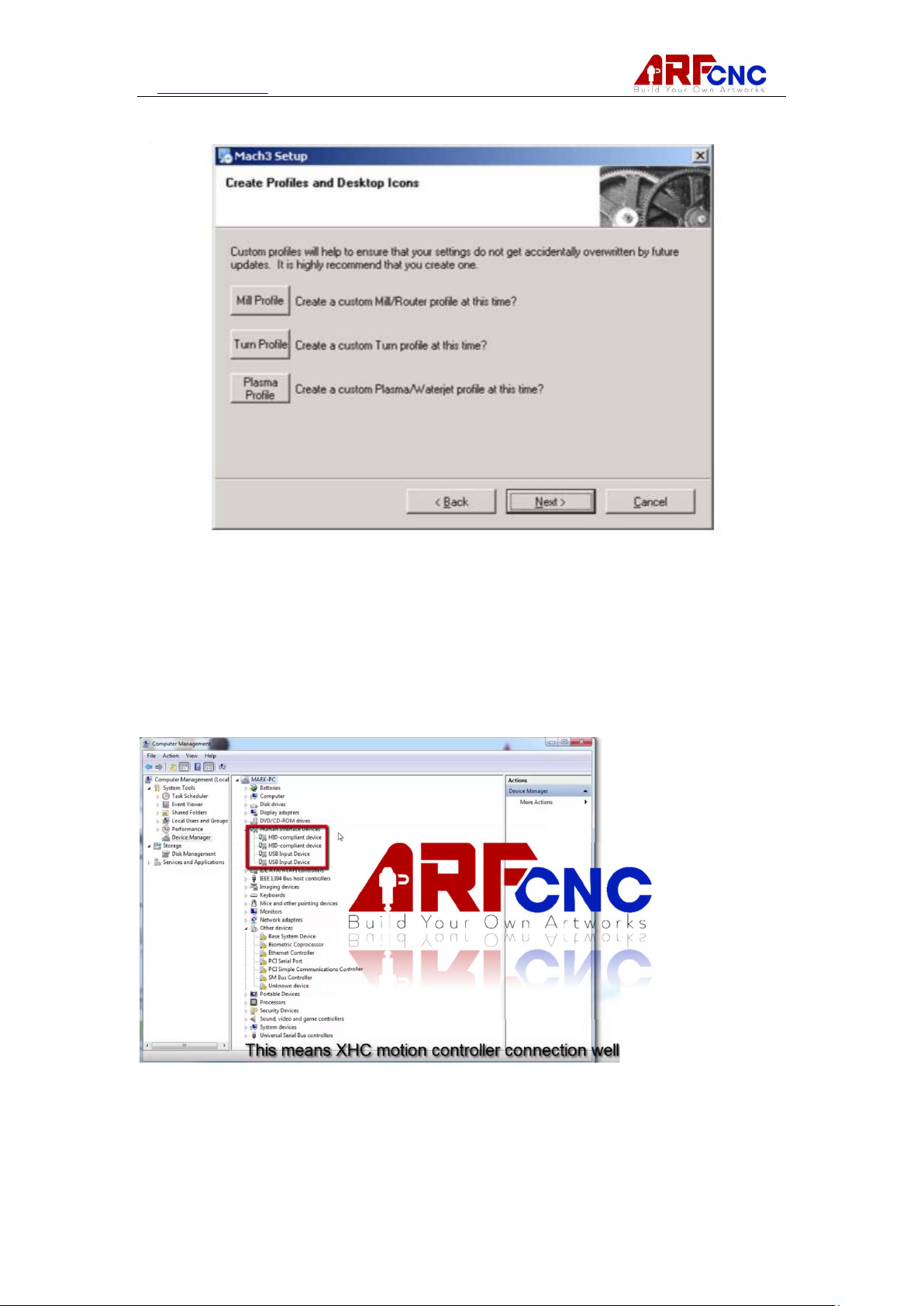
procedure will ask if you want to create a custom profile, as shown in Figure 3-2:
6 / 20
Page 7
www.hl-yeah.com
Here use default Profile and click the Next button.
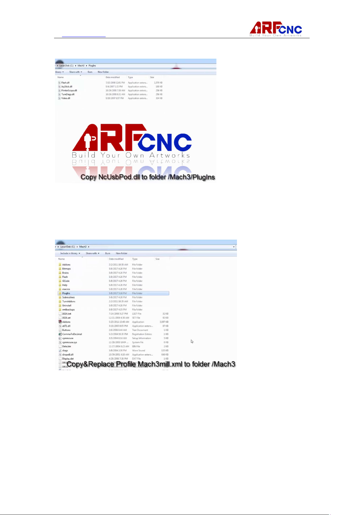
3.2.1 XHC USB Motion Controller Driver v2.38.8 Installing
Installing Connect Control box to laptop via USB cable. You will find 4 devices in red
box in Device Manager, as shown in figure
7 / 20
Page 8
www.hl-yeah.com
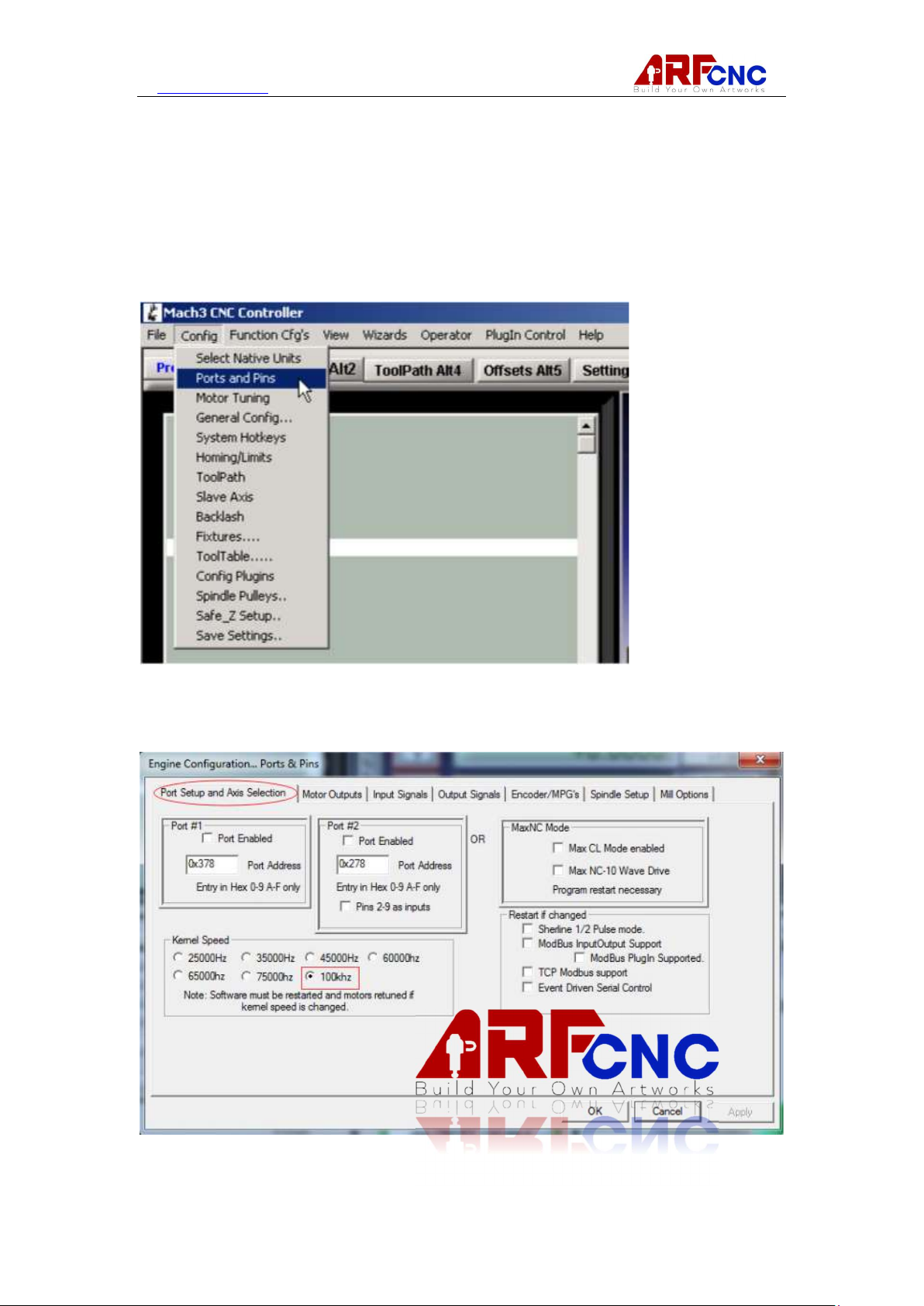
Copy NcUsbPod.dll to folder/Mach3/PlugIns
3.3.1Mach3 Profile Creation
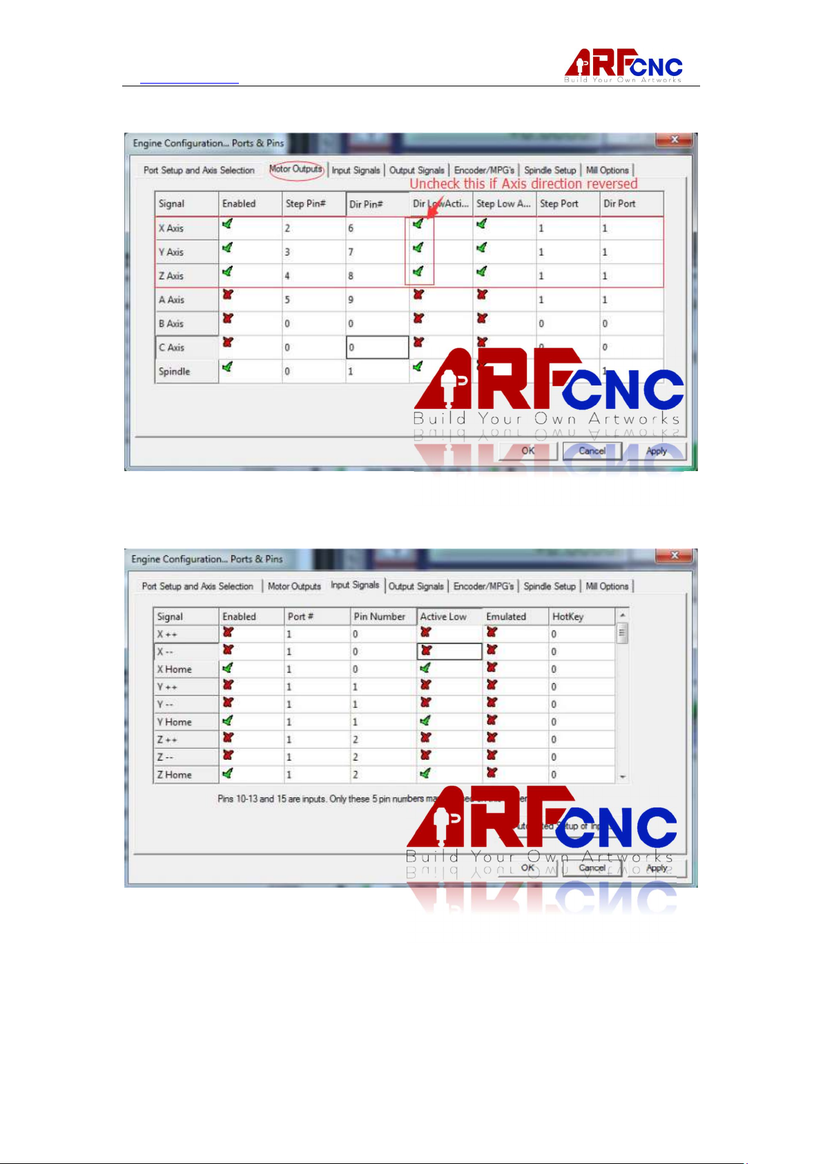
ARF CNC 6040, We create suitable Mach3 profile for you instead of setting up on
your own. Just copy& replace origin one in folder /Mach3.
8 / 20
Page 9
www.hl-yeah.com
Chapter 4 Machine Settings
Begin with the Config>Ports and Pins dialog. The Ports and Pins dialog has many
tabs
4.1.1 Port Setup and Axis Selection. Kernel Speed at 100khz
9 / 20
Page 10
www.hl-yeah.com
4.1.2 Motor Output
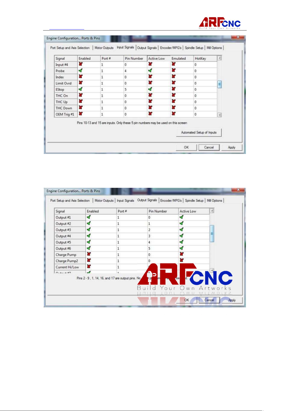
4.1.3 Input Signals
Enable X Home, Y Home, Z Home, A home, Probe, E-stop use Port#1 Pin 0,1,2,3,4,5
10 / 20
Page 11
www.hl-yeah.com
4.1.4 Output Signal
Enable Output#1 till #8 use Port #1 Pin 0 to 7.
11 / 20
Page 12
www.hl-yeah.com
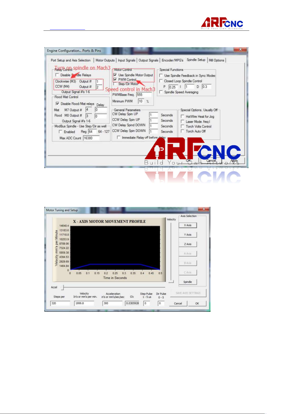
4.1.5 Spindle Setup
4.2.1 Motor Tuning
ARF CNC 6040 use 1605 ball screw. If units is mm, X,Y,Z Axis setting as below.
If units is inch, X,Y,Z Axis setting as below.
Step per inch -- 8125
Velocity per min. – 78.7
Accel in’s/sec -- 11.81
12 / 20
Page 13
www.hl-yeah.com
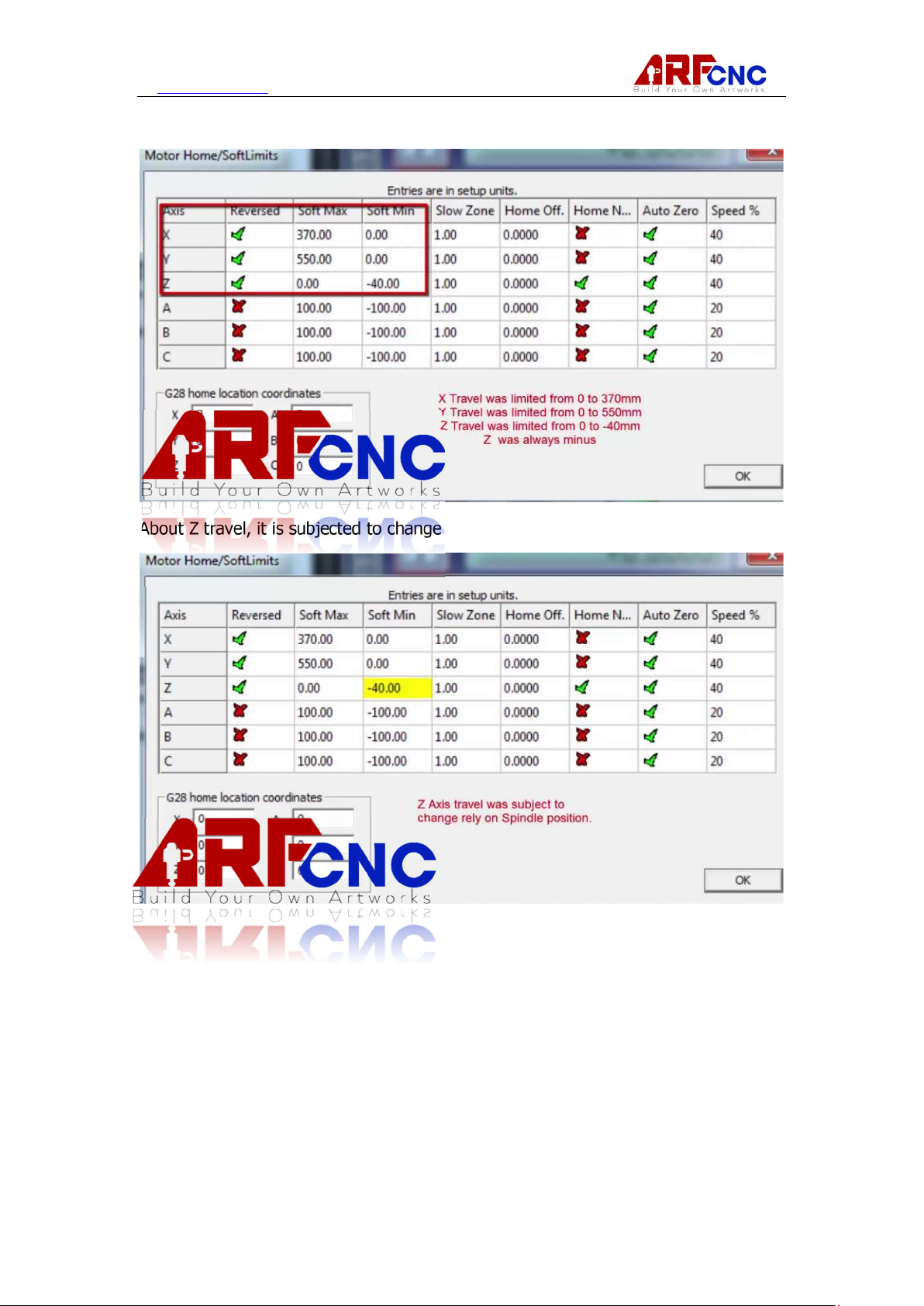
4.3.1 Motor home/Softlimits Setting
About Z travel, it is subjected to change due to spindle mounting position.
13 / 20
Page 14
www.hl-yeah.com
4.4.1 Probe Setting
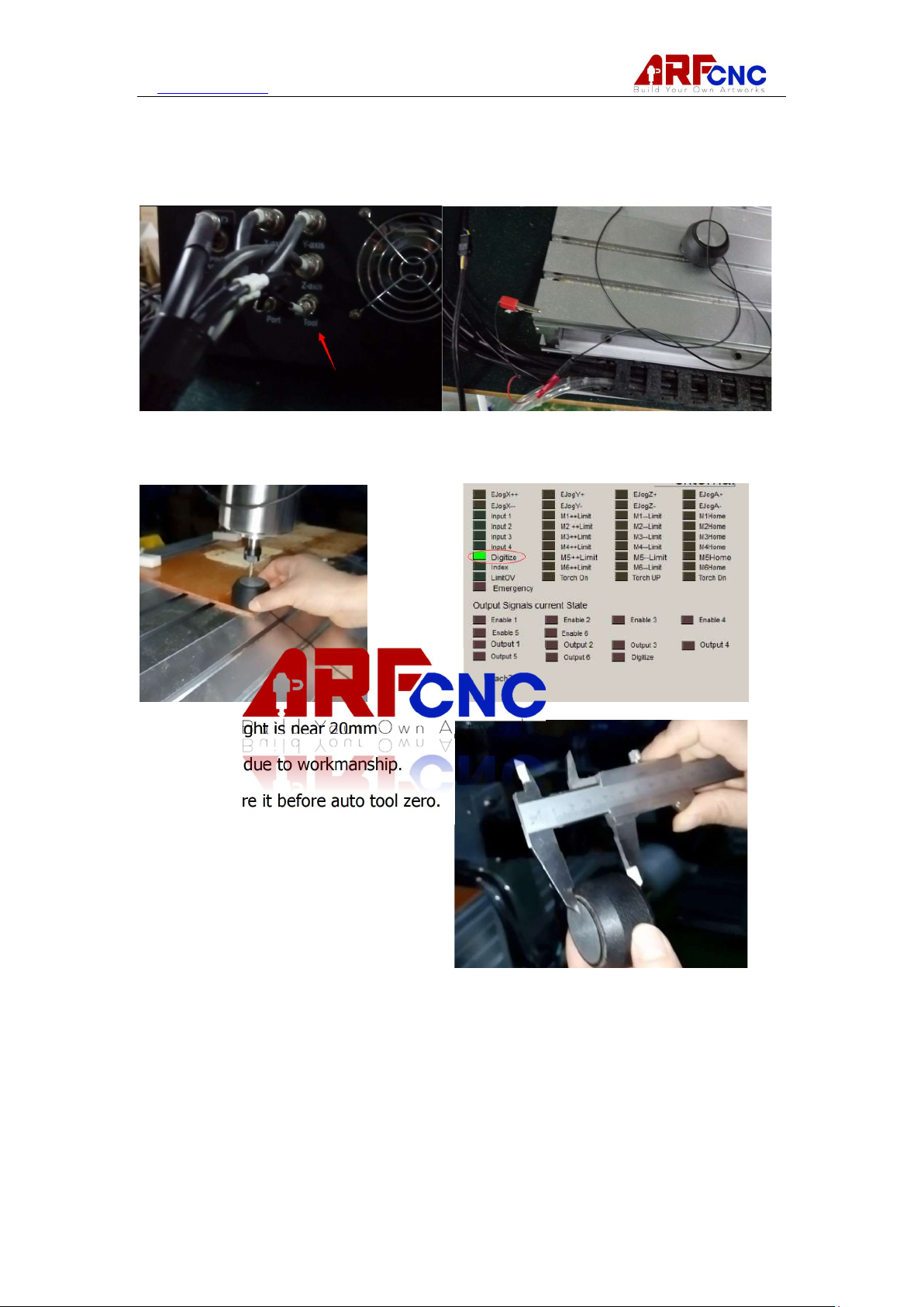
4.4.1.1 Physically, connect Probe to Socket”Tool” and other side grounded, as figure
4-4-1
In Diagnostics(Alt-7), Digitize led lit when engraving bit touch probe tool. That
means good physical connection.
Probe tool height is near 20mm
but may vary due to workmanship.
Please measure it before auto tool zero.
14 / 20
Page 15
www.hl-yeah.com
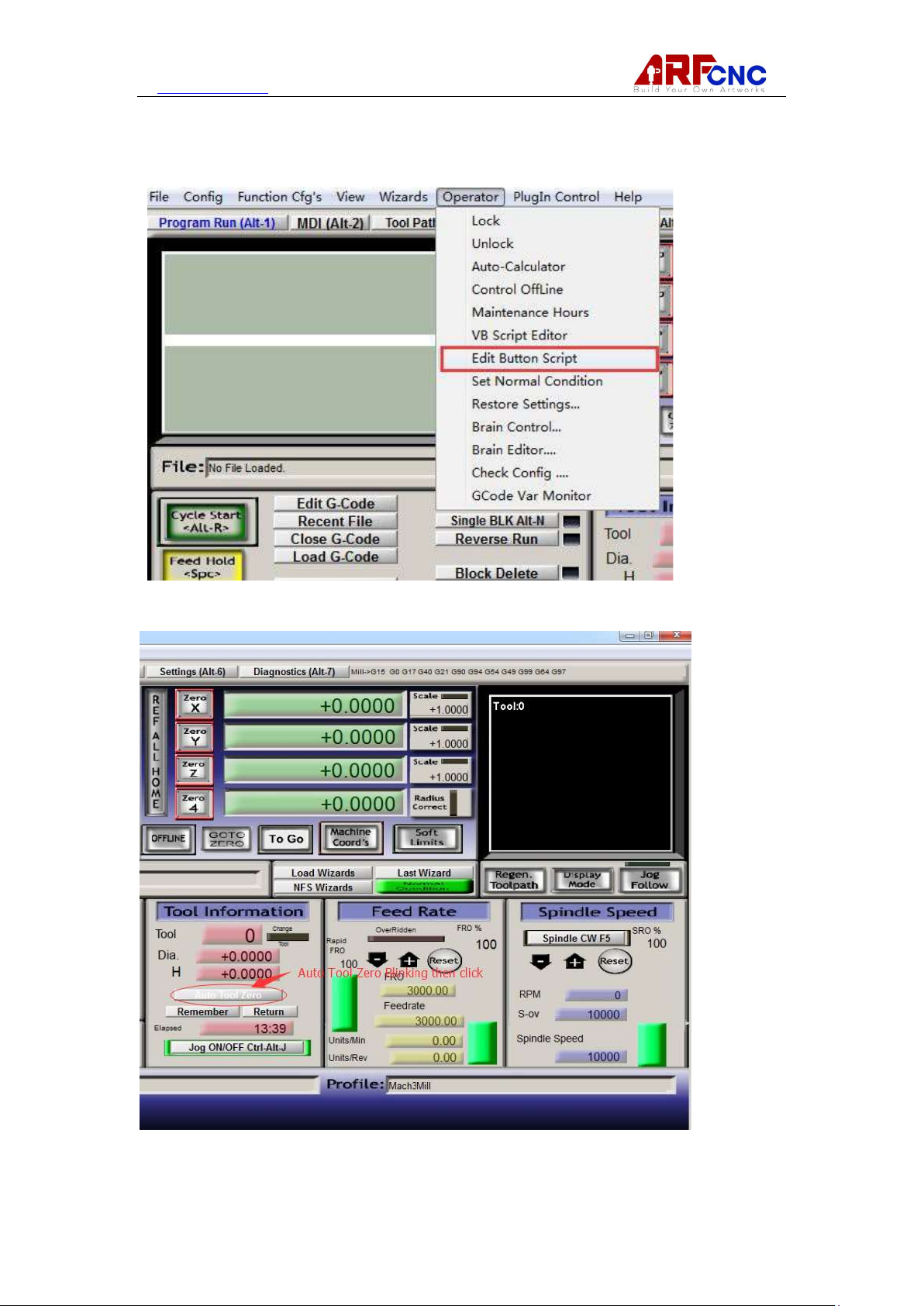
4.4.1.2 Import Auto tool zero script
To do this, we have to active script edit. Click Operator->Edit Button Script
Click Auto Tool Zero while blinking itself
15 / 20
Page 16
www.hl-yeah.com
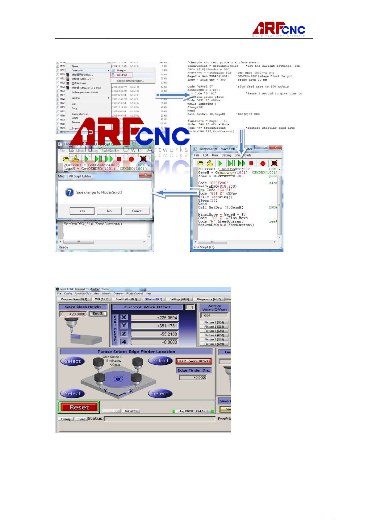
Open by
Follow by below steps to import Script(M930.m1s is file name)
WordPad
Copy& Paste
Save&Close
In Offset tab(Alt-5), input probe tool height which measure on section 4.4.1.1
16 / 20
Page 17
www.hl-yeah.com
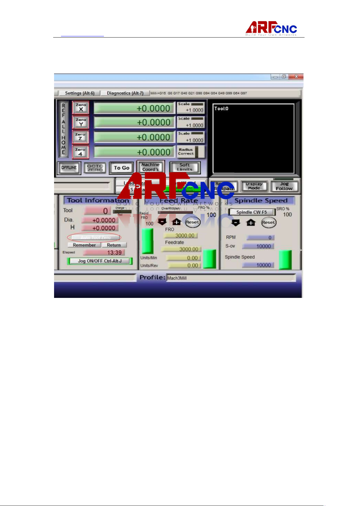
4.4.1.3 Tab Program Run(Alt-1), Execute Auto Tool Zero(while it is not blinking).
After it done, Z Axis value should be safe Z+ Probe tool offset eg. Safe Z is 10 and
Probe tool offset is 20, so Z Axis value equal to 30.
17 / 20
Page 18
www.hl-yeah.com
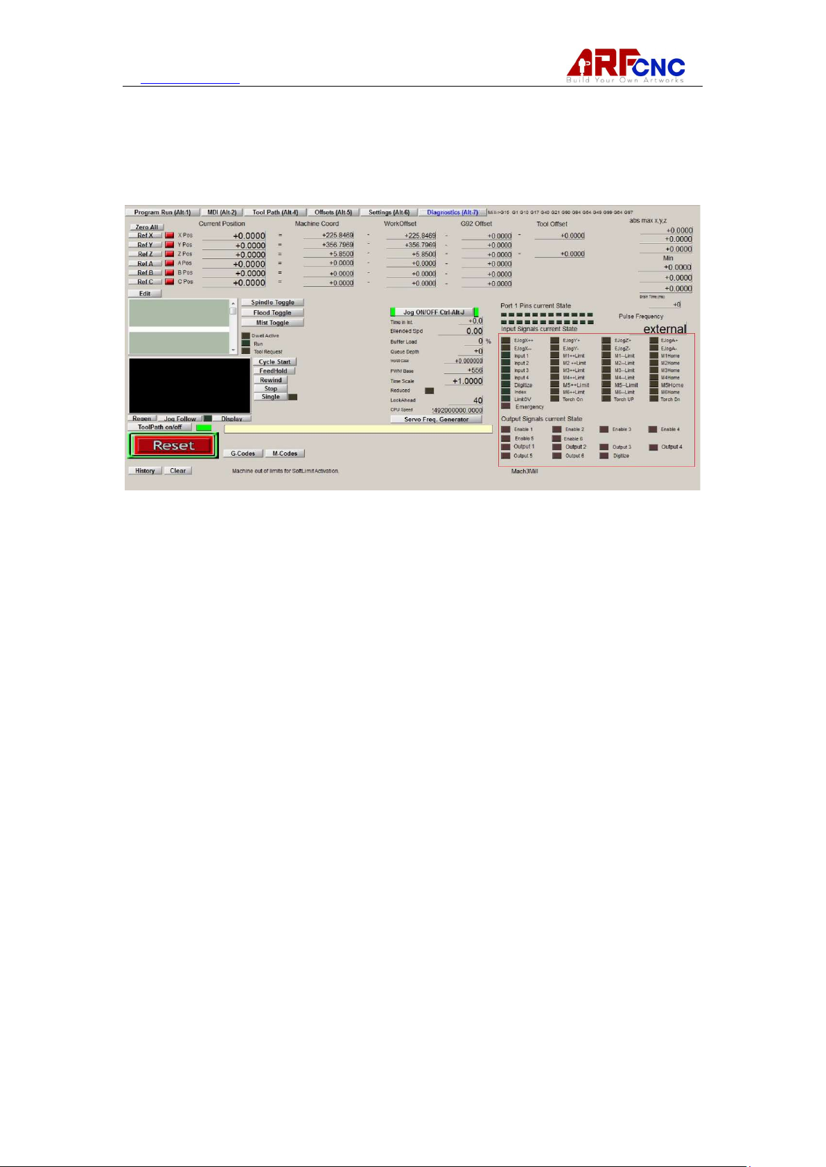
Chapter 6 Trouble Shooting
If any red led light, that means there is an issue in corresponding part. Please make
a snapshot and send to us.
18 / 20
Page 19
www.hl-yeah.com
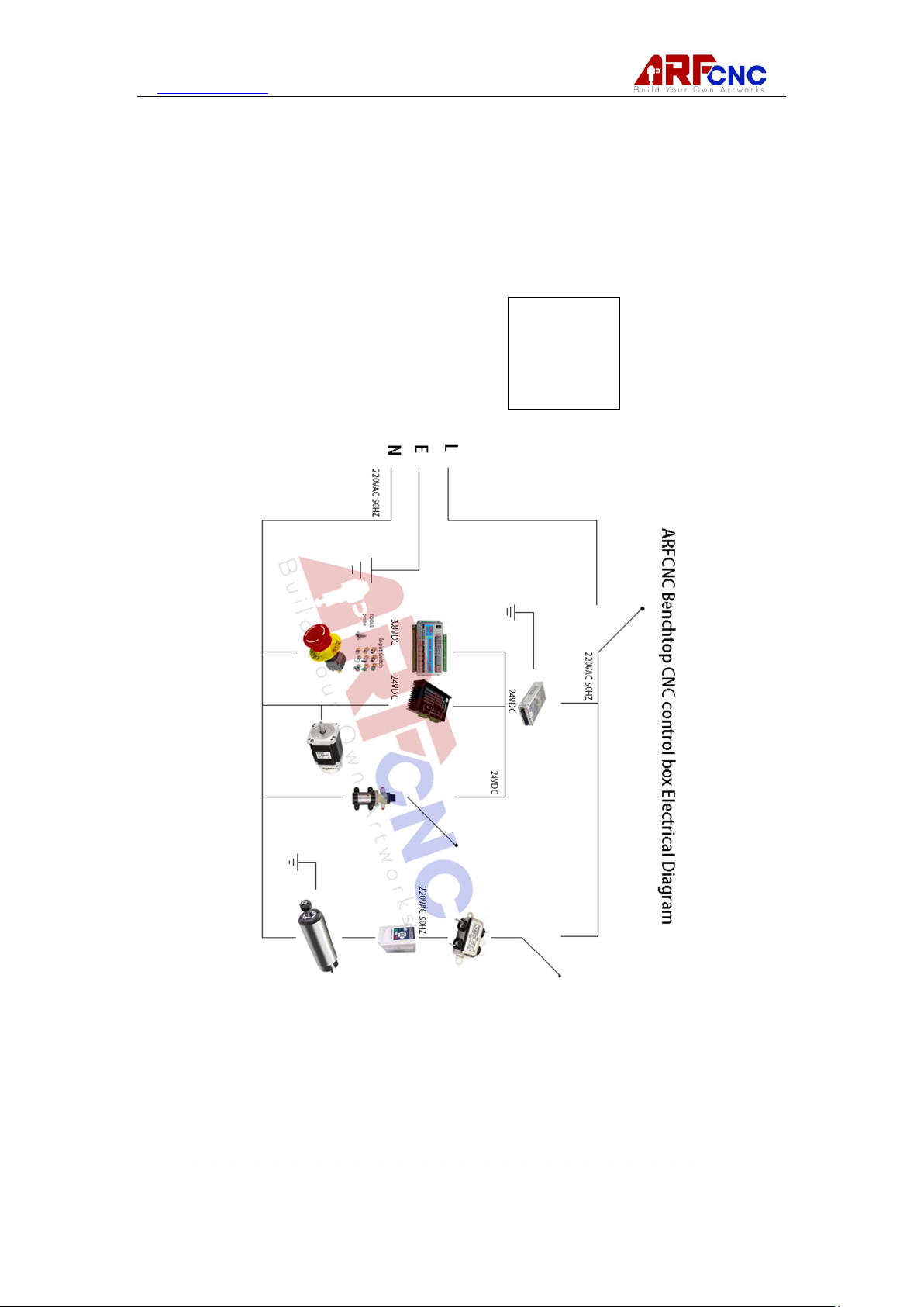
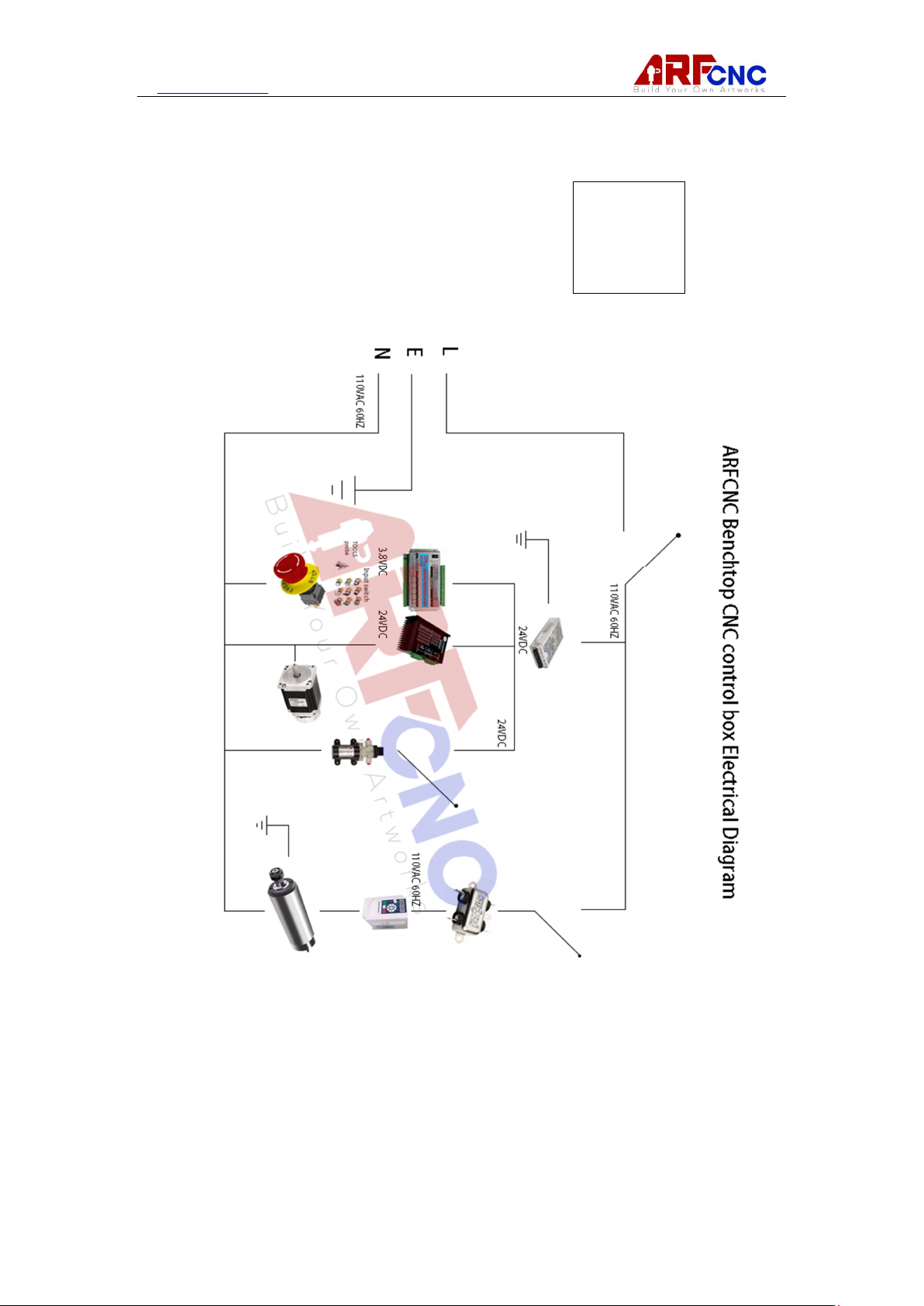
APPENDIX
220V Model
19 / 20
Page 20
www.hl-yeah.com
110V Model
20 / 20
 Loading...