

Page 1

Educational Design Robot
ROPE DANCER
INSTRUCTION MANUAL: Model WTR-RD1
© 2010 AREXX - THE NETHERLANDS
Page 2

English
CONTENT
1. Product information Rope Dancer 3
2. General assembly information 4
2.1 Parts list Rope Dancer 6
3. Assembly instructions Rope Dancer 7
4. Gears information 13
5. Motors 14
5.1 History of motors 14
5.2 Motor mechanisms 14
© English translation (January 2010): AREXX Engineering (NL).
This description is protected by the laws of copyright. Any partial or total reproduction of the contents
is prohibited without prior written authorisation of the manufacturer:
AREXX Engineering - Zwolle (NL).
The manufacturer and distributor cannot be held responsible for any damages occurred by mishandling,
mounting mistakes or misuse due to a non-respect of the instructions contained in this manual.
The specification, shape and size of the product are subject to change without prior notice.
Worldwide distributor:
AREXX Engineering
Zwolle, The Netherlands
For technical support see:
www.arexx.com
© 2010 AREXX Engineering
2
Page 3

English
1. PRODUCT INFORMATION ROPE DANCER
The Rope Dancer is a robot which can climb over a rope. Then it looks like if
he is dancing because of the movements of the rope. However, before this
robot can climb you have to build it first.
An excellent robot kit for beginners. This battery-controlled kit teaches the
basic principles of robotic mechanics and motion. This simple robot can be
assembled by almost anyone from age 8 and up. Only basic hand tools are
required for the assembly. We already included a screwdriver and a wrench
in this kit.
This robot kit is more than just fun. Assembling, building and following instructions help develop fine motor skills, hand-eye coordination and understanding
technical drawings.
Specifications:
Power source : 3V (2 Penlite AAA Batteries 1.5V, not included)
Current consumption : Approx. 100 mA max.
Height : 140 mm
Length : 170 mm
Width : 85 mm
Warning
- No return is possible after having opened the bags with components and pieces
- Prior to the assembly, read the manual thoroughly.
- Be careful when using tools.
- Keep this kit away from young children during construction and operation.
(They might get hurt by the tools or swallow small components).
- Observe the correct polarity of the batteries.
- Keep the batteries dry. When the Rope Dancer gets wet, remove the batteries and let
the Rope Dancer dry for some time.
- Remove the batteries when you will not use the Rope Dancer for a longer period.
- Children below 14 should only assemble this product with the help of adults.
- Use new batteries and do not MIX batteries (old, new, recharchable) in any way!
3
Page 4
English
2. GENERAL ASSEMBLY INFORMATION
IMPORTANT: First read all the instructions about the mechanics !
Follow the step-by-step instructions for the mechanical assembly as shown in this
manual. Read and work very accurately, this is the best way to avoid assembly failures.
When you follow the instructions and study the drawings and comments carefully, you
have a big chance the robot will work directly and without any problems.
Also a great help is the picture on the package. You can see very clearly how the robot
should look like. Best is that you only take out the parts from the packages and frames
the moment you need them! Sometimes parts or bags are numbered.
All parts fit perfectly so you do not need to use force assembling this robot!
Do not hurry and once more, best is to read all instructions first before you actually start
the assembly.
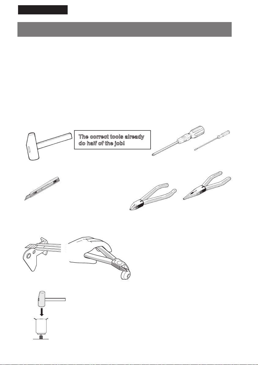
Small plastic Hammer
The correct tools already
do half of the job!
Screwdriverset
Always use a good fitting screwdriver size
Hobby knife
WARNING! Be carefull not to cut yourself
when using a hobby knife!
How to cut the plastic parts
Assembly of a gear to an ax
When you install a gear or a pinion to an ax or shaft, like the pinion
to the motor shaft, you must be very careful. Be 100% sure you
put the right gear onto the right ax. Best way is always to press the
gear on the shaft with your hands. When you cannot manage it
this way, use a very small plastic hammer. When you use a hammer, you can protect the gear or the shaft by putting a piece of
wood or carton between the hammer and the part you will hit on.
4
Plier set with cutting plier &
flatnose plier
Best plier size is approx. 150 mm.
To take out the plastic parts from a
frame, use a sharp hobby knife or a
cutting plier. Cut carefully and take
of the bosses with a knife to make it
smooth.
Do not cut parts from a frame
when you do not need them
directly!
Page 5
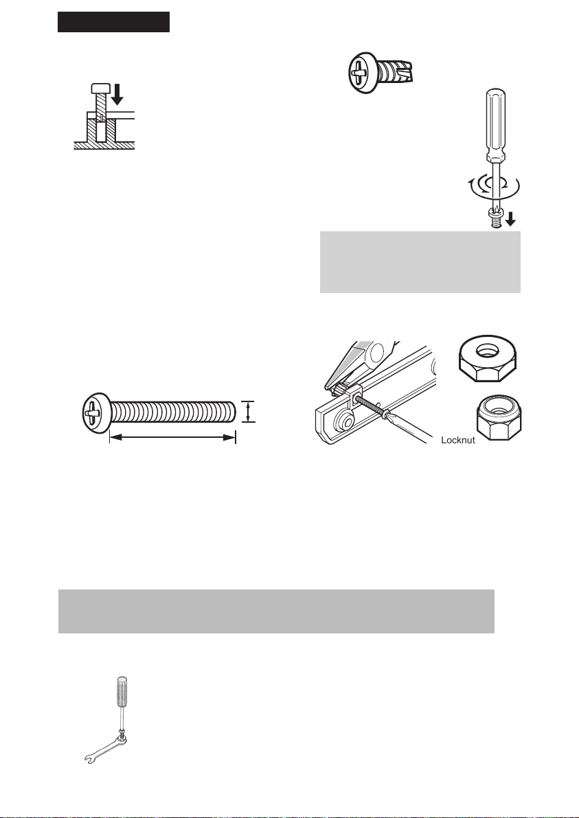
Locknut
English
Self-tapping screws (Parker)
A self-tapping screw looks similar to a wood screw.
When you screw it in a hole, it cuts the threads at
the same time. Never try to screw it down all the
way for a first time, because it may easily become
stuck or you will damage its head.
Tapping screws always have a sharp point,
sometimes with a small carve. They look
almost the same as screws which we use for
wood, only the thread is more fine. The best
way is to screw it in and out a bit.
Do not screw a tapping screw in and out too often because the screw hole may become enlarged and
the screw will loose all grip and proper function.
Screws and nuts
Thickness
Length
1. Screw in
2. Screw out a bit
3. Screw in further and continue
step 1 and 2
Nut
In a moving environment, screws and nuts must be tightened properly. A lock nut is a
special nut with nylon inside which will lock itself automatically.
Another easy way to lock a screw is to use ordinary fingernail polish. A big advantage
of nail polish is that you always can loosen it quite easily again. A professional way to
lock a screw is to use for example locktite, a sort of glue especially made for screws,
but it is very difficult to unlock such a screw afterwards.
The size of a screw is expressed by thickness and length. A screw with the marking M2 x 10
means 2 mm thick. The length of the thread is 10 mm. A M2 nut is used for a M2 screw, so the
nut always corresponds with the screw thickness.
Wrench
This kit includes a small wrench. Please use this wrench
to fit the M2 and M3 nuts in a proper way. You can use it
instead of a plier.
5
Page 6

English
2.1 Parts list ROPE DANCER
Please check all parts before you start the assembly!
M2 x 8
O 8 pcs.
Tapping screws
Roundhead
Thin
M2 x 5
O 2 pcs.
Motor
Pinion gear
O 1 pc.
8 teeth
Spacer
O 3 pc.
Ø 4 - 4mm
Screw middleScrew short
M3 x 14
O 2 pcs.
Roundhead
Thicker
M2.3 x 6
O 5 pcs.
Flat spur gear
with pinion small
O 1 pc.
28 and 10 teeth
Spacer
O 2 pc.
Ø 4 - 6mm
Screw long
M3 x 24
O 2 pc.
Flat spur gear with
pinion middle
O 1 pc.
30 and 10 teeth
Crank
O 2 pcs.
Flathead
countersunk
M3 x 6
O 2 pcs.
Wired
Wired
Nut Lock nut
M2
O 8 pcs.
Roundhead
with flange
M3 x 10
O 3 pcs.
Flat spur gear with
pinion big
O 1 pc.
32 and 10 teeth
RopeMotor
O 1 pc.O 1 pc.
M3
O 4 pcs.
Gear with shaft
O 1 pc.
40 teeth
Wire's
with connector
Complete set
pre-soldered
Motor holder Head
O 1 pc. O 1 pc.
Arm
O 2 pcs.
Battery holder
Wired
Leg
O 2 pcs.
6
Gearbox
side panel 1
Gear coverBody
Switch
Wired
O 1 pc.O 1 pc.O 1 pc.O 1 pc.
Gearbox
side panel 2
O 1 pc.O 1 pc.
Page 7

English
3. ASSEMBLY INSTRUCTIONS ROPE DANCER
First always check and collect all the parts, as mentioned in the parts list, before you start the assembly!
Step 1: Assembly of the gearbox
Assemble the gearbox as shown on the drawing below:
Gearbox
side panel 2
Flatspur gear
28/10
Flatspur gear
30/10
Flat spur gear
32/10
Gearbox
side panel 1
Gear
with shaft
Step 2: Installing the gearbox
To install the gearbox you need:
1 pc. Gearbox from step 1
1 pc. Body
4 pcs. Screw M2 x 8
4 pcs. Nut M2
Install the gearbox on the body as shown on
the drawing:
Screw M2 x 8
For the gearbox assembly you need;
1 pc. Flat spur gear with pinion small
1 pc. Flat spur gear with pinion middle
1 pc. Flat spur gear with pinion big
1 pc. Gearbox side panel 1
1 pc. Gearbox side panel 2
1 pc. Gear with shaft
Assemble the gear parts in order from
1 to 4.
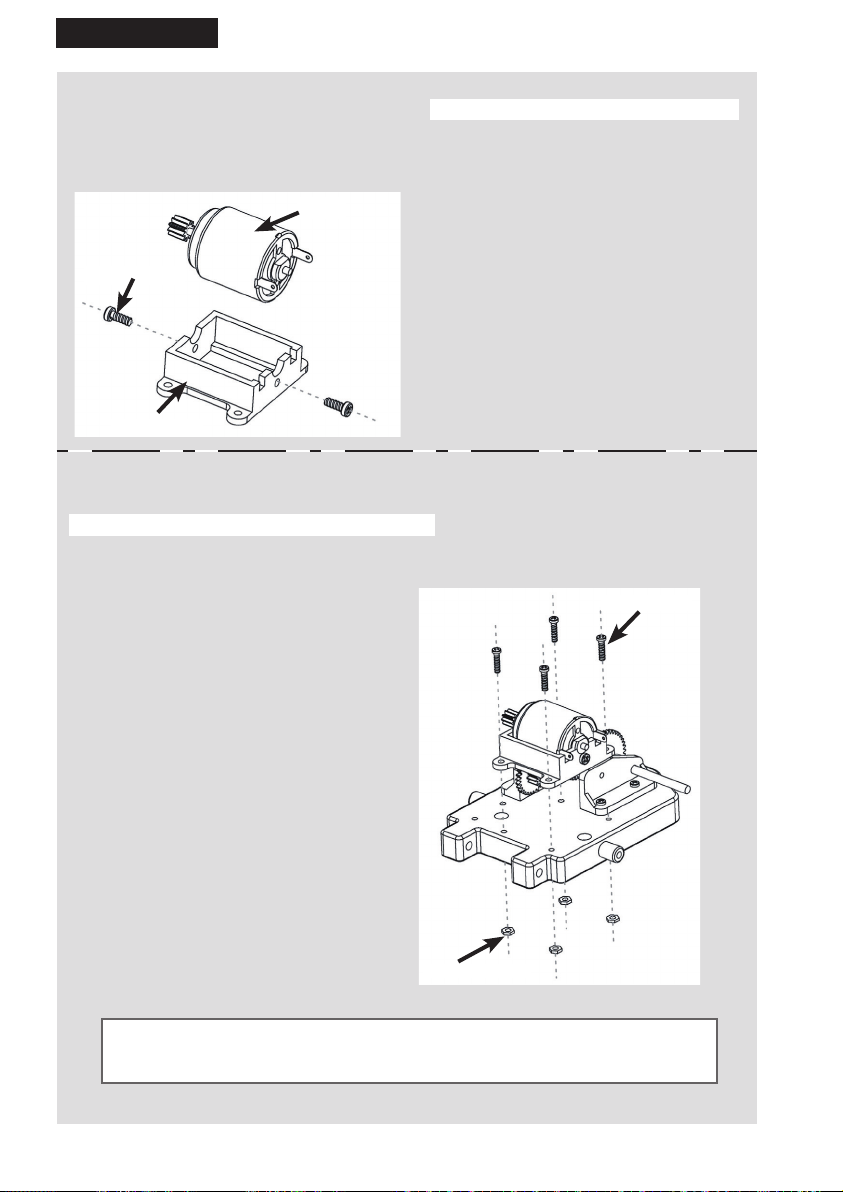
Step 3: Assembly motor pinion
For the motor pinion assembly you need:
1 pc. Motor pinion gear
1 pc. Motor
Put the pinion on the motor shaft as shown in
the drawings:
Place the pinion on the motor shaft and install by SOFTLY
tapping with a small hammer until pinion gear and motor shaft
are flush. The best way to do it, if you have enough force, is to
push the pinion on the shaft by hand, see the drawings below.
Nut M2
Body
Hit slightly with the hammer,
do not hit the terminals!
OR BETTER:
Push the gear on the shaft
with your hands.
The shaft must be fully
pushed into the gear !
7
Page 8
English
Step 4: Motor assembly
For the motor assembly you need:
1 pc. Motor of step 3
1 pc. Motor holder
2 pcs. Screw M2.3 x 6
Motor
Screw M2.3 x 6
Motor holder
Step 5: Installing the motor holder
To install the motor holder you need:
1 pc. Motor holder of step 4
1 pc. Body of step 2
4 pcs. Screw M2 x 8
4 pcs. Nut M2
Assemble the motor holder as shown on
the drawing:
Install the motor on the holder as shown on
the drawing:
Screw M2 x 8
nut M2
After this step,
we will name the partially assembled body: CHASSIS!
8
Page 9

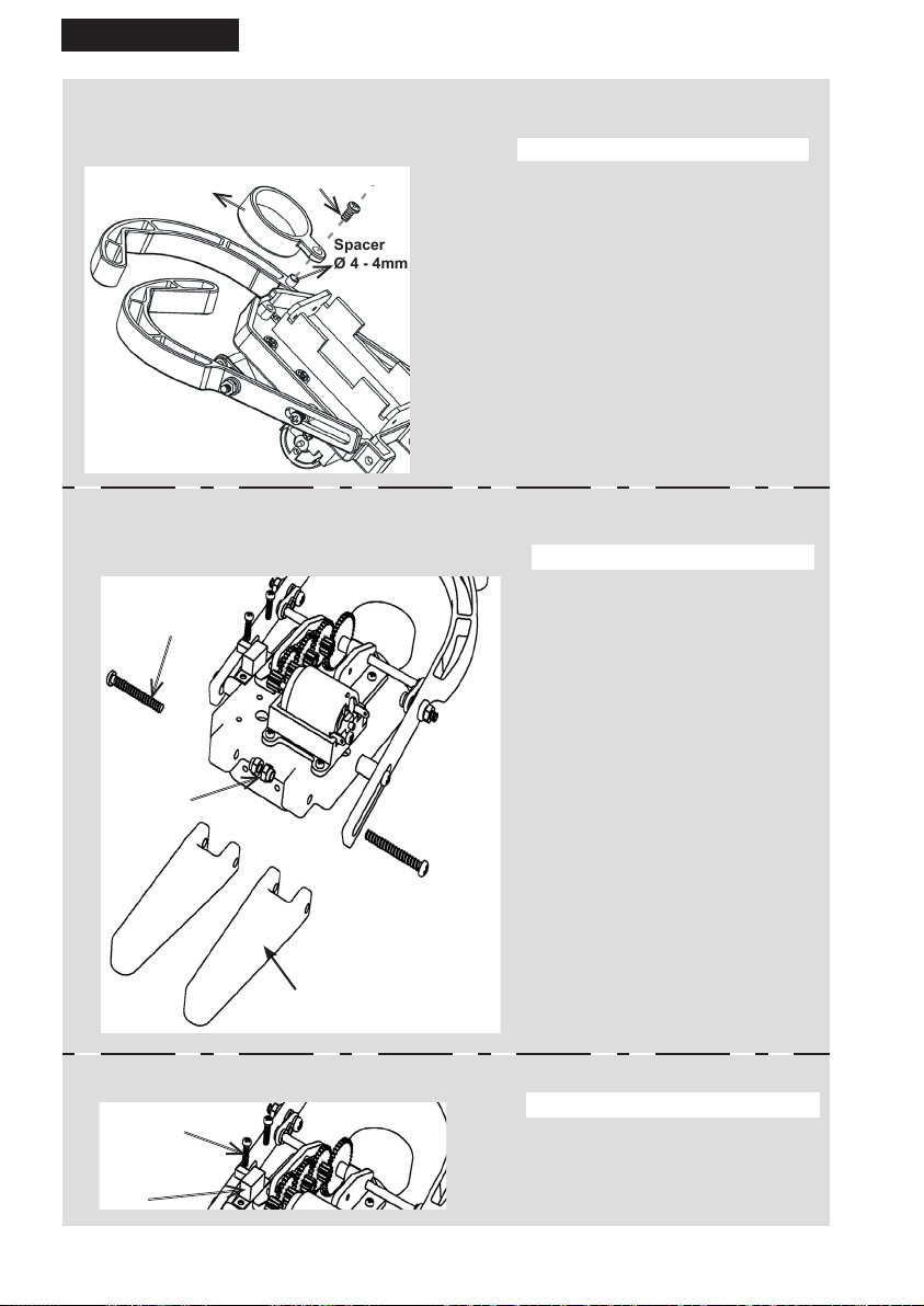
Spacer
Ø 4 - 4mm
Spacer
Ø 4 - 6mm
English
Step 6: Installing the arms
Assemble the arms as shown on the drawing:
Lock nut M3
Screw middle
M3 x 14
Crank
Crank
Screw roundhead
with flange M3 x 10
NOTICE!
Assemble the cranks 180 degrees.
Details are shown on the drawing!
To install the arms you need;
1 pc. Chassis of step 5
2 pcs. Arm
2 pcs. Crank
2 pcs. Spacer Ø 4 - 4mm
2 pcs. Spacer Ø 4 - 6mm
2 pcs. Screw middle size M3 x 14
2 pcs. Lock nut M3
2 pcs. Screw roundhead with
flange M3 x 10
Lock nut M3
Step 7: Installing the battery holder
Flathead screw
countersunk M3 x 6
For the battery holder installation
you need:
1 pc. Chassis of step 6
1 pc. Battery holder
2 pcs. Flathead screw
Countersunk M3 x 6
Battery holder
Install the battery holder as
shown on the drawing:
9
Page 10
Spacer
Ø 4 - 4mm
English
Step 8: Installing the head
Install the head as shown on the drawing:
Head
Screw M3 x 10
Step 9a: Installing the legs
Install the legs as shown on the drawing:
Screw M3 x 24
To install the head you need:
1 pc. Chassis of step 6
1 pc. Head
1 pc. Screw roundhead M3 x 10
1 pc. Spacer Ø 4 - 4mm
To install the legs you need:
1 pc. Chassis of step 8
2 pcs. Leg
2 pcs. Screw long M3 x 24
2 pcs. Lock nut M3
10
Lock nut M3
Leg
Step 9b: Installing the switch
Screw M2 x 5
Switch
To install the switch you need:
1 pc. Chassis of step 9a
1 pc. Switch
2 pcs. Roundhead screw M2 x 5
Page 11

Roundhead screw
M2,3 x 6
Gearbox cover
English
Step 10: Final assembly
Install the gearbox cover as shown on the drawing:
Step 11: The wiring diagram
For the final assembly you need:
1 pc. Chassis of step 9b
1 pc. Gearbox cover
3 pcs. Roundhead screw M2,3 x 6
Connect the wires as shown on picture.
Check the wiring carefull, it should exactly look the same like the drawing below:
11
Page 12

English
Step 12: Inserting the batteries
Place the batteries as shown on the picture:
The way the motor rotates is depending on
the polarity of the batteries!!
Last step: Practice test
Place the Rope Dancers arms around the
rope as shown on the picture and put
the switch in the ON position.
If the Rope Dancer does not move forward, change the polarity of the
batteries!
If the motor does not move at all check:
- Batteries: Are they FULL?
- Wiring: See page 11
- Gears: See page 7
Most likely problems are gear assembly
or poor batteries.
Worst case is that you have to
disassemble the Rope Dancer and
build it all over again.
Let op !
Monteer de vlakke
kant van de motoras
op de juiste manier.
12
Page 13
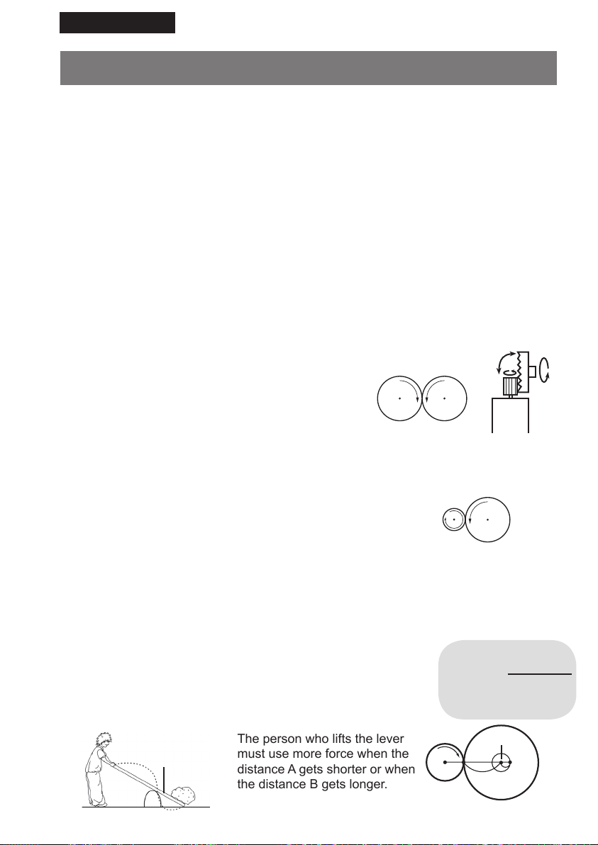
The person who lifts the lever
must use more force when the
distance A gets shorter or when
the distance B gets longer.
English
4. GEARS INFORMATION
The mechanics of the Rope Dancer consists of two parts. The first part is the gearbox,
which takes care that the power from the motor shaft is converted to the crank. The
second part is to convert the rotation of the crank into a movement of the arms.
Transmission of power
Gears, transmission belts, shaft, crank, chains: They all can transmit power. In the
Rope Dancer, four gears transfer the motor power into the crank. Such a transmission
is called a gearbox. The Rope Dancer motor rotates very fast with only a little torque.
However, for the crank we need low rotation speed and high torque. The power is
transmitted by the teeth of the gears. At the same time, three conversions take place:
a. Change in rotating direction
b. Change in rotating speed
c. Change in torque
a. Change in rotating direction
When two gears are connected, there will be a change
in rotation direction. One gear will rotate clockwise,
the other gear will rotate counter-clockwise.
Left rotation
Right rotation
90º
b. Change in rotating speed
The change in rotating speed depends on the relation of the
teeth in the gear. As an example we describe a gear with 10
teeth and a gear with 40 teeth. When the first gear
(10 teeth) makes a full rotation, the second gear (40 teeth)
only makes a quarter of a rotation. So before the second
gear makes a full rotation, the first gear already makes four
rotations. You may understand that this effect also changes the
rotating speed.
c. Change in torque
The torque can be seen as a lever construction with a
fulcrum. Imagine a person who lifts a stone with a lever.
Lever
A
Fulcrum
B
40
Teeth
10
Teeth
Motor rotation
Rotation =
Ratio Rotation last
gear
Fulcrum
B
A
Page 14

English
5. MOTORS
Explanation of motors:
There are many things around us in which motors are used. For example, a mobile
phone uses a motor for the vibration mechanism. A fan inside of a hair dryer is turned
by a motor. Motors are also being used to turn the wheels of a train.
If there were no motors in the world, our present life would not be as
it is.
5.1 History of motors
The prototype of the first electric motor was made by an English physicist, Michael
Faraday, in the beginning of the nineteenth century and was based on the discovery
of electromagnetic induction. Faraday noticed that when electricity ran into a generator
which had the same structure as a motor, it started to turn. On account of the fact that
the generator was invented earlier than the electric motor, this story is probably true.
Around the same period, an American physicist, Joseph Henry, was also working on a
prototype electric motor. However, because Faraday made his research presentation
earlier, he is regarded as the inventor of the motor.
5.2 Motor mechanisms
Electric motors turn by using the power of two different kinds of magnets. One is a
regular magnet (permanent magnets), which you know as a magnet. The other is the
electromagnet which is made by running the electric current through it. Both types of
magnets have north and south poles. The polarity of permanent magnets will not
change; The polarity of electromagnets will switch when the
electric current flow changes direction. Both types of magnets
have the characteristic that like poles they attract each other,
and unlike poles they repel each other.
N
S
N
S
How are magnets used in motors? Common DC motors in small sized plastic
models, such as the Rope Dancer, consist of the following items: permanent magnets,
turning axles, electromagnet cores wrapped with enameled wire, commutators to
change the direction of electric current flow of the electromagnets and brushes to make
contact with commutators. When the electric current is running to the motor from the
outside, the core becomes magnetized.
Then the core starts turning because of
attraction and repulsion, which are created
by the polarity of the electromagnet and the
permanent magnets around it. When the
electromagnet’s south and permanent magnet’s north
attract each other, the core would stop. However, the
electric current flow inside the electromagnet will be
reversed by the commutator. As a result, the electromagnet’s polarity will become the same as the permanent
magnet. Since like poles repel, the core will turn again.
By repeating this cycle, the core will continue to turn. The
axle of the motor is attached to the core and will rotate
as the core turns.
N
S
S
N
14
 Loading...