

Page 1

AREXX WIRELESS KITS
ARX-WRL
MANUAL: WRL-03
© AREXX - NETHERLANDS V0512
- 1 -
Page 2
Inhaltsverzeichnis
1. Product description WIRELESS KITS 3
2. Warnings 4
3. Bluetooth 5
4. Android 7
5. Wireless Transceiver kit 10
6. PC Wireless communication 14
7. APC-220 16
8. The Bluetooth module 19
9. Android software aplication 22
10.1 APC-220 24
10.2 Bluetooth 24
11. Visual Basic 26
11.1 Software development 28
11.2 Eclipse 29
xx. APPENDIX 31
A. RP6v2 USB programmer circuit 32
B. RP6v2 USB Programmer PCB layout 33
C. Wireless PCB kit circuit 34
C. Wireless PCB layout 35
D. Bluetooth module 36
NOTICE!
AREXX and AREXX WIRELESS KIT is a trademarks of AREXX, The Netherlands and JAMA, Taiwan.
AREXX and JAMA are registered trademarks
All rights reserved.
Reprinting any of this instruction manual without our permission is prohibited.
The specifications, form, and contents of this product are subject to change without prior notice.
We are not liable for disadvantage or damage caused by improper use or assembly.
Technische help see forum:
WWW.AREXX.COM
Fabrikant:
AREXX Engineering
JAMA Oriental
© 2012 AREXX Holland und JAMA Taiwan
© 2012 Deutsche Übersetzung: AREXX - Die Niederlande
Europäischer Importeur:
AREXX Engineering
ZWOLLE Die Niederlande
WWW.ROBOTERNETZ.DE
- 2 -
Page 3

1. PRODUCT DESCRIPTION WIRELESS
1.1. Introduction
The „Wireless“ transmission module from AREXX is an extension
set for the ASURO robot that is also suitable for other robot models
such as the AREXX Arduino (AAR) or the PRO-BOT from Conrad. The
„Wireless“ transmission module contains the circuits for standardized infrared communication so that you can continue to use the
ASURO USB-IR transceiver with the ASURO Flash software.
Moreover this extension module offers space for an APC220 or a
Bluetooth module. Both modules are bases on radio transmission.
The main advantage of radio transmission is the fact that ASURO
doesn’t need any visual contact with the control unit, the control
range is bigger and the robot is easier to control e.g. via an android
mobile phone.
The „Wireless“ transmission module is supplied fully mounted. Only
the contact pins need to be soldered. Almost all components are
pre-soldered so that you need no extra time for the soldering.
The challenge of the set lies in the programming of the control
software. Programming tutorials are available on the website. The
control can be done via a PC or an android mobile phone.
Visual Basic offers a programming environment for the transmission
application on the PC. The example application is user-adjustable.
You can connect to the Bluetooth module via a mobile phone so that
the system can send data both ways. This communication takes
place in an android environment that is quickly developing towards a
control system for mobile radio transmission. The ASURO extension
set, this manual and the available software offer you the opportunity
to get acquainted with Android.
Enjoy your extension set the its RF modules!
- 3 -
Page 4

2.5.1 CAUTION
• Read this manual carefully in advance to fully understand
how to assemble this product.
• Children below 14 should can only assemble this product
with the help of adults.
• Be careful about tools. Especially be careful about sharp
tools such as nippers or cutter knife to prevent any injuries or
accidents.
• Never assemble the kit when a younger child is around. The
child might touch sharp tools or swallow parts and a vinyl bag.
• Be careful about sharp edges of parts.
• Do not mix old and new or recharchable and non rechargeble
batteries.
• Take out the batteries when you do not use the robot for more
than a week
- 4 -
Page 5

2. Bluetooth
2.1 History
The Bluetooth technology was developed by the company Ericsson.
Bluetooth is an open standard for wireless transmission between
units over short distances. Just imagine mobile radio units with a
wireless headphone connection or data transfer between mobile radio units or a GPS receiver that sends wirelessly data to a
telephone.
In 1994, Ericsson developped Bluetooth as a wireless way of communication between mobile radio units and other systems.
Jaap Haarsen who worked at that time for Ericsson, developed the
most important technical part. The name Bluetooth comes from the
king of the vikings Harald Bluetooth. Initially, Bluetooth was the
name of the project and as no better alternative had been found,
this name has been kept for the end product.
The communication system spreads very quickly and after a short
time, the biggest electronic companies come together to set up the
‘Bluetooth Special Interest Group’ (SIG).
A worldwide application needs to be made available worldwide.
Therefore a universally applicable frequency has been searched and
found in the 2,45GHz frequency range.
2.2 Technology
Bluetooth is a radio transmission of speech and data over short
distances. The selected communication structure is a point to multipoint link which means that one transmitter can transmit to several
receivers. As soon as two Bluetooth units start communicating, a
so-called „piconet“ is set up. Several pico networks make a scatter
network.
- 5 -
Page 6

Within a pico network Bluetooth supports a maximum of 8 active
units whereas 127 units can operate a communication link that is
temporarily kept in a passive state (parked) (g. 1).
Fig. 1 : Scatternet
The energy consumption of Bluetooth is extremely low: 30 microamps in passive standby mode and 8 to 30 milli amps in active
state. This low consumption allows Bluetooth to be used also in
battery powered mobile units.
Bluetooth systems are divided in 3 different categories:
Category 1: Projects for long distances (up to 100m)
Category 2: For standard distances (up to 10m)
Category 3: For short distances (10cm to 1m)
- 6 -
Page 7

3. Android
3.1 Background information
Android is an „open source“ platform for mobile units such as
Smartphones and Tablets that have been developed by the company
Android Inc.. In 2005, Android has been taken over by the company
Google.
The unveiling of the Android distribution in 2007 was announced
with the founding of the Open Handset Alliance, a consortium of 40
hardware, software, and telecommunication companies devoted to
advancing open standards for mobile devices .
Android is based on a Linux kernel and the Java program environ-
ment.The SDK development tool (Software Development Kit) allows
not only Google but also other developers to create applications.
They can subsequently offer these applications to the android
market. On this market, end users can search and install
applications. Here you can nd also all information about the
applications. The distribution of applications whether they are free of
charge or charged, is promoted. The developers are allowed to offer
these applications also outside the android market.
The applications are developed for a specic android version.
However they are retrocompatible. That means that an application
that has been developed for android 2.2 can also be run under 2.3.
The versions published so far are listed in the g. 2 table.
The number of users per version is indicated in g. 3 below
the table.
- 7 -
Page 8

Ice Cream Android 4.0 19-10-2011
Honeycomb Android 3.2 15-07-2011
Honeycomb Android 3.1 10-05-2011
Honeycomb Android 3.0 02-02-2011
Gingerbread Android 2.3 06-12-2010
Froyo Android 2.2 20-10-2010
Eclair Android 2.0 26-05-2010
Donut Android 1.6 15-08-2009
Cupcake Android 1.5 30-04-2009
Erste Publikation Android 1.1 10-02-2009
Fig. 2 : Android-version
Fig. 3 : Users per Version ( State: 03-11-2011)
- 8 -
Page 9

3.2 The Software Development Kit (SDK)
Google unveiled the SDK software so that users are able to write their
own applications for a smartphone, a tablet PC or both. The SDK con-
tains a collection of various helpful tools such as a debugger tool and
an emulator plus a series of example applications and tutorials on the
website.
Open following link to download the SDK:
http://developer.Android.com/sdk
On this page you will nd the installation les and extensive instructions on how to install the SDK.
3.3 Eclipse
Eclipse is an open source framework of the Eclipse Foundation, a non-
prot association for software development environment. The most
popular application is the development environment for the Java programming language.
The SDK contains an Eclipse plug-in that enables a programmer to
easily start, compile, debug and emulate an android project.
The Eclipse programme is an open source software and can be downloaded on following
http://www.eclipse.org/downloads/
3.4 Hello World
The „Hello World“ programming instructions explain how easy it is
to transfer the text „Hello World“ in an application to a terminal. The
instructions explain step by step how you have to start a project up to
the very last step, how you represent the „Hello World“ in the emulator.
The website of the tutorial is:
http://developer.Android.com/resources/tutorials/hello-world.html
- 9 -
Page 10
4. The Wireless control set from AREXX
The „Wireless“ control set allows you to install an APC220 module
or a Bluetooth module on ASURO or other robots. Thus you can
communicate with the ASURO not only via Infrared but also via RF
frequencies. The advantage of the high frequencies is that transmitter
and receiver don’t need visual contact any more.
ASURO can communicate with the PC if an APC220 is installed on the
Wireless radio set. You will nd further information on this subject in
chapter ‘APC220’. The Bluetooth module allows you to communicate
with the PC and an android smartphone. You will nd further
information in chapter ‘Bluetooth Module’.
4.1 Specications
The AREXX „Wireless“ control set includes:
• IR-receiver or transmitter for the Flash transmission to ASURO
• Socket for the APC220 or Bluetooth RF module
• Switch for the IR or RF transmission
• Experience board to build an additional circuit
• Connection options for free gates of ASURO
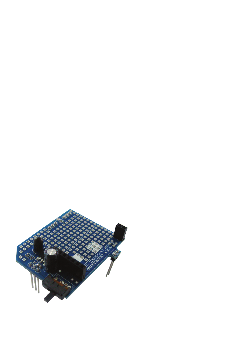
Following gures show the layout of the PCB. The free
experimentation area for the additional circuit is clearly visible.
There will be even some space left below the APC220 because it is
installed in some distance to the PCB.
Please note!
Fig. 4 : Wireless extension kit
The switch on the PCB allows 2
positions: (1) Infrared connection
or (2) Bluetooth / APC220 communication.
If you want to transfer the software
via Flash into ASURO or if you wish
to communicate via Infrared, this
switch must be set to ‘IR’.
If you want to communicate via
Bluetooth or APC220, the switch
must be set to the other position.
- 10 -
Page 11

4.2 Installation on the ASURO robot
The installation of the „Wireless“ radio modules can be explained in 3
steps:
Step 1.
First of all the ASURO PCB must be prepared as follows for the installation of the „Wireless“ radio module:
1. Unsolder the components at the locations marked in red and
remove them from the PCB (g. 9). Use a specic soldering iron or
special unsoldering tin to unsolder the components.
Caution:
Make sure not to damage the solder lugs because you
will need them later for the re-soldering.
Abb. 5 : Lötachen
B.2. Solder the supplied socket parts on these connection areas.
Install the 1x3 socket on the connectors featuring three adjacent
areas. The shape of the area is not important. Now you can solder
the remaining 1x2 sockets on the free connection areas
- 11 -
Page 12

Step 2.
Install now the ASURO extension set on the ASURO PCB. The set
should t accurately into the previously installed socket parts.
Fig. 6 : ASURO with radio control PCB (Side view)
Fig. 7 : ASURO with radio control PCB (Front view)
- 12 -
Page 13

Step 3.
Install now either the APC220 or the Bluetooth module.
Fig. 8 : ASURO with Bluetooth
Fig. 9 : ASURO with APC-220
The installation of the hardware is nished. Now you can establish a
connection with the various applications.
In chapter ‘APC220’ we explain how you can control ASURO via the
APC220 module.
The chapter ‘Bluetooth module’ explains how the Bluetooth communication will work.
- 13 -
Page 14

5. APC220/Bluetooth with PC radio data communication
In order to install a communication link between the PC and Asuro we
need a dongle. We decided to use the RP6v2 Programmer adapter
(WT Dongle).
Fig. 10 : RP6v2 USB Programmer
(WT dongle)
For wireless communication from the PC we prefer the APC220 radio
data module or a Master Bluetooth module. These modules are modest
in energy consumption and easy to install, which are convincing details in choosing the components for robotic designs.
5.1 Setup for the wireless PC-communication link
Frequency and baud-rate for the APC220-modules will be setup at
standard values with the help of the WT-dongle. For this purpose a
special software for the WT-dongle has been written in Visual Basic
(VB), which provides us with an easy setup. This software may be
found in the APC-220 application’s software.
Connect the WT-dongle with the PC by USB-cable. Additionally the
RP6v2 programmer adapter requires the installation of a driver software. The most recent driver will be found at the RP-robot’s section in
our website.
The APC220- respectively Bluetooth-module is to be inserted at the
WT-dongle. Use the Visual Basic program APC-220 application to setup
the APC-220 and to control the robot.
WT
PC
Fig. 11 : Communications example PC <--> Robot
The blockdiaram shows how the wirelss communication setup is between PC
and robot.
dongle
APC-
220
APC-
220 ASURO
- 14 -
Page 15

5.2 Preparation for the wireless communication
Important!
The robot cannot communicate through a wireless connection yet.
Besides the hardware modication, when the wireless extension PCB
is mounted on the robot, a program must be loaded.
1 2
PC or Phone
TRANCEIVER 1
In case of Android communication, an application should be loaded
in an Android Smartphone or tablet. In case of PC communication,
transceiver 1 is placed on RP6v2 USB Program Adapter (WT dongle)
and the application must be installed on the PC.
TRANCEIVER 2
First the extension set must be installed with the RF module
APC-220 or Bluetooth. Finally, the correct software has to be loaded
in the robot.
The software depends on the robot type:
*.HEX (Hex le) for:
- ASURO
- RP6(v2)
- ROBOT ARM
*.PDE (Arduino le) for:
- AAR of andere Arduino robots
Robot
*.CBAS (C-Control le) for:
- PRO-BOT128
- 15 -
Page 16

6. APC220
In combination with the APC220 module, ASURO can be controlled
via the „ASURO control“ programme that needs to be installed on
the PC. “ASURO Control” can be downloaded from the website. The
software has been written in Visual Basic and is available to the user
as a variable source.
The ASURO software needs to be slightly adjusted. This software is
also an open source product.
The adjustment is necessary because the system has to transfer a
protocole that includes a control byte and a set of information bits.
Fig. 12 shows how the application (in orange) transmits the signal
for the data request at the PC. The ASURO system replies with the
reply data in red.
Protocole from ASURO to PC:
Fig. 12 : Communications exaomple
The ASURO software contains some functions to send requests to
the sensors and to control the motors. If the control programme
sends a request, ASURO transmits immediately the data to the
client. At this stage you have the option to add 4 more information
bytes to the signal. This could e.g. be a thermometer that is
connected to the free connectors of the extension set.
The following text describes the code for the data transfer of this
kind of measurement data.
- 16 -
Page 17

This code shows that the system calls a few functions in Battery ()
e.g. in order to measure the battery voltage. This function supplies a
value between 0 and 255 that is processed in the PC programme and
displayed on the terminal. The bytes 10 to 13 are free and can be
freely programmed.
Fig. 13 : Asuro Control Software (Visual Basic)
Once the application ‘ASURO CONTROL’ has been started, the programme displays the screen above. Now you can get in contact with
ASURO and control the robot. The WT dongle must be connected to the
PC. When the WT dongle is connected, a click on the ‘Refresh’ function
triggers a request to all connected COM ports.
Once you have selected the correct COM port for the WT dongle, the
connection will be established by clicking on the ‘Connect’ function on
the ASURO control screen. This command triggers the link between the
WT dongle and the ‘ASURO Control’.
Consequently the motor speed and the battery voltage will be displayed in the bottom right corner of the screen. As soon as a switch on the
front panel of the robot is activated, the programme marks this switch
as a red dot. This way the programme shows a collision on the ‘ASURO
Control’ display. The programme display of the application shows also
the colour change of the ASURO LEDs.
- 17 -
Page 18

The ASURO robot can be controlled via buttons on the right side.
The speed is set via a slider on the upper right side. Moreover is it
possible to control the robot via a keyboard. To this end, you need
to tick on the field ‘Key Control’.
W: Forwards
A: Left
S: Backwards
D: Right
E: Stop
There are several ways to set the operating frequency of the
APC220. If several APC220’s are operating close to each other,
the protocole will make sure that the data will be sent to the right
ASURO.
However, it is recommended to avoid this kind of situation and if
possible, choose different transmission frequencies as some programmes communicate several times per second with ASURO.
The APC220 operating parameters are set in the PC programme and
can be adjusted. Click on ‘Settings’ in the main dialogue page of the
programme so that following contents are displayed (fig. 14) :
Fig. 14 : Settings in
Control Programm
- 18 -
Page 19

7. The Bluetooth Module
You can control ASURO via a PC or a telephone if you install a Bluetooth Slave module inside the extension module. To do that, you
need to install a Bluetooth Master module on the WT dongle. The
difference between the Slave and the Master module is shown in
g. 15 and 16.
Afb. 15 : Slave
Afb. 16 : Master
Those Bluetooth modules are only available in the ARX-WRL03 KIT
The master module (right-hand side) is marked with a white dot on
the upper IC. Moreover the module features a switch.
The slave module (left-hand side) has no white dot and no switch.
Once both modules are switched on, the Master will look for a Slave
and establish automatically a connection. Once the connection has
been established, the Master will save the slave address.
If the connection is interrupted and the Master will be looking for its
slave again at a later stage, the system will only look for the Slave
whose address has been saved.
- 19 -
Page 20

This situation is shown by the blue LED. In this procedure following
operating modes are dened:
Fast ashing: Slave and Master are not connected together
Steady on: Slave and Master connected together
Slowly ashing: The Master is not connected but it has saved a
slave address. In this case you can erase the
saved address by pressing the switch.
You can chose a name for the
Bluetooth Slave module. In order
to let the system communicate
with another Bluetooth unit, the
adjustment of the baud rate and
the PIN code has been installed as
an option.
You can change these parameters
in the ‘settings’ menu on the main
page. Click on ‘settings’ in
the software to display following
contents.
Fig. 17 : Bluetooth Settings
The module that you want ot adjust must be in the WT dongle when
you make the changes. The changes will saved by clicking on the item
‘save settings’.
The Log protocole shows if the saving process was successful. If this
is not the case, a so-called ‘time-out’ is announced.
Please note:
The name of the Master module cannot be changed. Once you have
saved the baud rate and the PIN code, a time-out is announced. This
is normal.
- 20 -
Page 21

Once the Bluetooth Master module has been installed in the WT
dongle or the Slave in the ASURO extension kit, a communication
link can be established with ASURO exactly as for the APC220.
Start the ‘ASURO Control’ programme. The COM port remains the
same and the same steps as described in the APC220 chapter are
executed.
- 21 -
Page 22

8. Android mobile phone application
If you want to control ASURO via a mobile phone, you need to install
the Bluetooth Slave module on the ASURO extension kit.
After that, you have to install the ‘ASURO Bluetooth’ application on
your mobile phone. This software is available on the AREXX website.
In the same area you can download the source code for this
application so that you can input the source and match it to your
own needs.
Most android mobile phones are tted now with the operating
system Android. Therefore this application has been written for
Android 2.1 or Android 2.1 or higher.
Fig. 18 : ANDROID APP
After the start of the application, the programme is asking for permission to start Bluetooth if this hasn’t happened yet. The interface
is very clear.
- 22 -
Page 23

As soon as you click on the ‘options’ key of the unit, the programme
opens a window with the message ‘Connect a device’ and
‘Disconnect’.
These commands are self-explanatory: rst of all, the telephone has
to establish a connection with the Slave module.
With the command ‘Connect a device’ you are asking the telephone
to search for Bluetooth units nearby. As soon as the name of a Slave
module appears, you can click on the name and the system will establish the connection.
Once the link has been set up, you can control ASURO via the application.
- 23 -
Page 24

7. Background Information
7.1 APC220
Communication between the PC and Asuro may be accomplished by
a APC220 radio data module, which is a transceiver from Appcon
Technologies.
A transceiver is a combination of a transmitter and a receiver in a
single chip, which allows us to transmit and receive signals by using
only one singular device.
The transceiver has been equipped with a UART-interface, which
enables the module to communicate with a PC or a micro-controller.
Fig. 19 : APC-220
Fig. 20 : RF Communication
The module’s energy consumption is low (+/- 30mA) and installation
is rather simple. These features are the basic reasons to choose the
module for wireless communictions.
The communication range at a baud-rate of 9600 bps is specied at
a maximum of 250m and at 1200 bps at 1200 meters. These specications may be found in the data-sheet.
In a previous project (Wild Thumper) the same APC220-module has
been implemented and extensively tested. In these tests a 200m-
range for reliable communications has been conrmed.
The disadvantage for this receiver is the missing proprietary protocol
for transmitting data. Therefore we will have to dene this protocol
for transmitting data.
- 24 -
Page 25

7.2 Bluetooth
Bluetooth is an open standard for exchanging data between systems over short distances and has been developed by Ericsson as
an RF-communication link between mobile phones and other equip-
ment. Communication uses the 2,45 Ghz-band and does not require
a line-of-sight connection. The high GHz-frequency band allows
Bluetooth-signals to penetrate and pass concrete materials as long
as they do not contain metals.
Bluetooth-systems may be considered as alternatives for cableconnections and is used to interconnect all sorts of equipments. The
developers concentrated on cheap radio-technology, which enables
us to integrate Bluetooth in any electronic design.
Bluetooth’s low energy consumption (30 micro-amperes in ‘hold
mode’, respectively 8-30 mA during active communication phases)
allows us to use the system in mobile equipment which depend on
battery power supplies. Standard Bluetooth-systems (class 2)
ranges up to 10 meters.
Modern mobile phones usually have been provided with Bluetoothmodules, which is a good reason for us to install Asuro- and other
AREXX-robots with Bluetooth
- 25 -
Page 26

8. Visual Basic
An application will be needed to use a PC to control the Asuro robot.
A great variety of programming languages is available for such
applications.
Initially normal students will not be experienced in developing applications. Therefore we decided to choose Visual Basic, which provides
an easy way to develop applications.
Visual Basic (VB) is a programming language and a development
tool, allowing is to create software for the Windows operating system. The attribute “Visual” refers to the Graphical User Interface
GUI) and the attribute “Basic” refers to the programming language
BASIC (Beginners All-Purpose Symbolic Instruction Code).
The project had been set up to work with Visual Basic 2010, which is
the most recent version available today.
Fig. 21: ISP connector
- 26 -
Page 27

Fig. 21 illustrates the main program’s window. In the left box we
may identify the area to insert buttons, timers and text-boxes. As
a user you might adapt attributes for these elements’ and refer to
these elements in your programming code.
If you press the ‘refresh’ - button at the window the button’s driver
software will be activated.
Private Sub Button_Refresh_Click
(ByVal sender As System.
Object, ByVal e As System.EventArgs)
Handles Button_Refresh.Click
GetSerialPortNames()
End Sub
On activating the ‘refresh’ - button the above sample code will call
the function ‘GetSerialPortNames()’.
- 27 -
Page 28

8.1 Software Development Kit
In order to enable users to write their own applications for
smart-phones, tablets or both Google released a Software
Development Kit (SDK). This SDK provides us with a number of
sophisticated tools, such as a debugger and an emulator.
The relevant website also contains a great number of sample
applications and tutorials.
The SDK Manager (gure 22) allows the user to add platforms to
his development workspace. He may also choose to install various
sample applications.
Fig. 22 : SDK Manager
- 28 -
Page 29

The SDK also provides us with a Virtual Device Manager (gure 23).
This Android Virtual Device Manager enables the user to dene a
virtual device, which allows the designer to emulate and debug his
newly created software.
Fig. 23 : Vritual device manager
You may download the SDK from the following website:
http://developer.android.com/sdk
This site provides us with the installation package including detailed
instructions for the SDK’s installation procedure.
- 29 -
Page 30

7.5 Eclipse
Eclipse is an open-source software framework, designed by the
Eclipse Foundation for software development purposes. The most
popular application is a development environment for the programming language Java.
The SDK has been equipped with an Eclipse plugin, which enables a
software developer to easily start an Android project, including compiling, debugging and emulating the software.
At completion the designer will create an .apk-le for the
application’s installation, which may be transferred to any Android
telephone.
Fig. 24 : ECLIPSE
The freeware Eclipse-software is available for download at the website:
http://www.eclipse.org/downloads/
- 30 -
Page 31

APENDIX
- 31 -
Page 32

B. Circuit diagram RP6v2 Programmer (WT DONGEL)
X1
USB
123
4
DC-JACK
J1
10n 100n
C1 C2
ferrite bead 600 ohm 100Mhz
L1
321
+
22uF
C9
GND
100n
C5
+
22uF
C4
GND
100n
+3V3
C3
25
FT232RL
GND
GND
GND
GND
18
21
7
GND
100n
17
15
16
3V3OUT
USBDP
USBDM
TEST
12
26
CBUS4
CBUS3
OSCO28OSCI
CBUS023CBUS122CBUS213CBUS314CBUS4
DCD
RI
CBUS2
CBUS1
CBUS0
Vtarget
100K
GND
R3
R4
1K
R6
3K9
VCC
BC847
T1
R5
1K
BC847
T2
APC220
C6
20
19
27
DSR
DTR
9
10RI6
DCD
DTR
DSR
1
GND
IC1
VCC
VCCIO4RESET
RXD
CTS
RTS
3
11
2
5
RTS
RXD
CTS
GND
DTR
100
3
6
7
EN
AUX
SET
470R
470R
R2
TXD
1
TXD
UART-FULL-HDR
RXD
R8
5
LED_TX
Blue
CBUS0
RI
DTR
CBUS4
1
9
5
HDR1
CBUS43VTARGET
DTR7TX
RI
CBUS2
GND
DSR
RTS
RX
4
2
8
10
6
RXD
RTS
DSR
CBUS2
TXDTXD
GND
100n
100
RXD4TXD
C7
R7
2
M1
VCC
VCC
GND
R1
LED_RX
Blue
CBUS1
Vtarget
VCC
3
IC2
VIN
REG1117
VOUT
1
GND
2
100n
C8
+
MBRS130LT3
22uF
C10
D1
VCC
- 32 -
Page 33

A. RP6v2 USB Programmer (WT DONGEL)
- 33 -
Page 34

D. CIRCUIT DIAGRAM AREXX EXTENSION KIT
A
B
C
D
E
25-10-2011
Joris Kok
Designed by:
Extensiekit
AREXX Engineering
www.arexx.com
SW1
1
2
3
JP8
3
GND
2
1
JP8
JP7
2
1
JP7
JP6
2
1
JP6
GND
5V
IRLED-
IRLED+
GND
IR_LED
SFH415-U
C4
GND
GND
V+
PC2(ADC2)
AVCC_2
PB3(MOSI/OSC2)
GND1
PD6(AIN0)
PD2(INT0)
PC3(ADC3)
AVCC_1
10uF
JP4
1
2
3
JP5
JP4
1
2
JP5
JP3
1
2
3
JP3
1 2 3 4 5 6 7 8
SWITCH_IR_OR_MODULE
5V
VCC
100n
C3
GND
GND
GND
GND
220uF
GND
C1
+
EN
AUX
SET
OUT
OUT
SFH5110
C2
MODULE
100n
VCC
2
RXD
4
TXD
5
EN
3
AUX
6
SET
7
GND
1
APC220
GND
V1.1 Aanpassing gedaan aan RXD signaal en LED, deze moet aan de - van de LEd en niet aan de +
1 2 3 4 5 6 7 8
A
B
C
D
E
- 34 -
Page 35

C. AREXX WIRELESS EXTENSION KIT
POSITION PINHEADER LAY-OUT, other components are not drawn or wrong
- 35 -
Page 36

1 2 3 4 5 6 7 8
1 2 3 4 5 6 7 8
E. CIRCUIT DIAGRAM BLUETOOTH SLAVE
2
1
PIN
7
6
R2
5
4
27k
3
2
1
CON
GND
GND
IC1
3
VIN
VOUT
C2
GND
100nF 10uF
GND
1
47k
R1
GND
2
GND
HC-06-S_MODULE
HC-06
1
TX
2
RX
3
CTS
4
RTS
5
PCM_CLK
6
PCM_OUT
7
PCM_IN
8
PCN_SYNC
9
AIO0
10
AIO1
11
RST
12
3V3
13
GND
C1 C3
GND
NC14VBUSD-15CSB16MOSI17MISO18CLK19VBUSD+20GND1
100nF
21
PIO11
PIO10
PIO9
PIO8
PIO7
PIO6
PIO5
PIO4
PIO3
PIO2
PIO1
PIO0
GND2
GND
F. CIRCUIT DIAGRAM BLUETOOTH MASTER
34
33
32
31
30
29
28
27
26
25
470
24
23
R3
22
GND
GND
BLUE
LED1
GNDREG1117
2
1
PIN
7
6
R2
5
4
27k
3
2
1
CON
R1
GND
47k
GND
IC1
3
VIN
VOUT
C2
100nF 10uF
GND
1
GND
2
GND
HC-06-M_MODULE
HC-06
1
TX
2
RX
3
CTS
4
RTS
5
PCM_CLK
6
PCM_OUT
7
PCM_IN
8
PCN_SYNC
9
AIO0
10
AIO1
11
RST
12
3V3
13
GND
C1 C3
GND
GND
NC14VBUSD-15CSB16MOSI17MISO18CLK19VBUSD+20GND1
100nF
21
PIO11
PIO10
PIO9
PIO8
PIO7
PIO6
PIO5
PIO4
PIO3
PIO2
PIO1
PIO0
GND2
34
33
32
31
30
S1
29
28
27
3 1
26
25
24
23
22
GND
GND
470
24
R3
BLUE
LED1
GNDREG1117
GND
- 36 -
 Loading...