

Page 1

Design Soccer Robot
SOCCER ROBOT
MANUAL: Model SR-129
© AREXX - THE NETHERLANDS 2006
- 1 -
Page 2

Contents
1. Product information SOCCER ROBOT 3
2. Tools 4
3. Parts list 6
4. Assembly instructions 8
5. Final assembly 18
6. Troubeshooting 18
7. SOCCER ROBOT game 19
8. How does the SOCCER ROBOT move 19
9. Information about gears 20
© (April 2006, Manual): AREXX Engineering (NL).
All rights reserved. Reprinting any part of this manual is strictly forbidden without the written approval of the
European Importer:
AREXX Engineering - Zwolle (NL).
Manufacturer and Dealer are not responsible for the consequences of improper use, assembly mistakes and or
operation of this product as a result of ignorance of this manual. If necessary, the contents of this manual can be
changed any time without prior notice.
European Importer:
AREXX Engineering
ZWOLLE The Netherlands
© AREXX - HOLLAND & CHINA
- 2 -
Technical support:
WWW.AREXX.COM
Page 3

1. PRODUCT INFORMATION SOCCER ROBOT
Play your own World Championships of Soccer Robots!
Before the games begin, first you have to assemble the SOCCER ROBOT.
When the SOCCER ROBOT is ready, you can start your own Soccer
Championships. First however, an extensive training is necessary because it
is not so easy to control this funny, six-legged robot. The controller has two
switches to control the two motors. These two motors send the robot in any
direction you like.
The performances of this fast robot will certainly appeal to you. In this manual
we will show you all robot movements, so you really will get to know the
functions of this SOCCER ROBOT.
Specications:
Power voltage : 3V (2 Penlite Batteries of 1,5V
(Batteries are not included in this kit)
Power consumption : Approx. 300 mA max
Height : 100 mm
Length : 160 mm
Width : 90 mm
Cable length controller : 1.5 meter
Warning
* When you open the plastic bags of the parts the return right is no longer valid
* Before you start assembling, first read the complete instruction manual
* Be careful with tools and always keep them away from little children!
* Keep this product out of reach of children and do not build this kit when children are
in the neighbourhood, the tools and parts are dangerous for children
* Check the polarity of the batteries when you insert them
* Keep the batteries dry and when the robot gets wet, remove the batteries and let the
soccer robot dry for some time
* Remove the batteries when you are not using the robot for a longer period
- 3 -
Page 4

2. TOOLS
We strongly suggest to read this chapter rst before assembling the product
Assemble the robot in the exact order as described in this manual. This way you will
avoid assembly mistakes. If you assemble in the correct order and study the picture on
the packaging so now and then, you will build a perfectly functioning robot in no time.
All parts fit perfectly, so there is absolutely no need to use force. Work calmly and read
the complete manual before you start to assemble this robot.
Small hammer
With the correct tools
you already solved
half the job!
Long nose plier
Detaching parts from a frame
Assembly of shafts and gears
Screwdriver set
Always use the correct size
for each screw
We recommend to use electronic pliers (150 mm).
When a part is fixed to a plastic
frame you have to detach it with
a diagonal cutter or ahobby knife.
Make sure that you do not cut in the
part itself and remove all burrs neatly.
Important !
Do not detach parts from the
frame before you need them.
Be always very careful when you assemble shafts and
gears. When possible always try to push the gear on the
shaft with your hands. When you need to use a hammer,
always put a piece of wood between the hammer and the
gear or shaft, so you do not damage things.
- 4 -
Page 5

Self-tapping screws (Parker)
thickness
A self-tapping screw looks similar to a wood screw.
When you screw it in a hole, it can cut the threads
at the same time. Never try to screw it down all the
way for a first time, because it may easily become
stuck or you will damage its head.
Tapping screws always have a sharp point
sometimes with a small carve. The best way
is to screw it in and out a bit.
1 Screw in
2 Screw out a bit
3 Screw in further and continue
step 1 and 2
Do not screw a tapping screw in and out to often because the screw hole may become
enlarged and the screw will loose all grip and proper function.
Screws and nuts
Nut
Length
Lock nut
In a moving environment, screws and nuts must be tightened properly. A lock nut is a
special nut with nylon inside which will lock itself automatically.
Another easy way to lock a screw is to use ordinary fingernail polish. A big advantage
of nail polish is that you always can loosen it quite easily again. A professional way to
lock a screw is to use for example locktite a sort of glue especially made for screws,
but it is very difficult to unlock such a screw afterwards.
The size of a screw is expressed by thickness and length. A screw with the marking M2 x 10
means 2mm thick. The length of the thread is 10mm. A M2 nut means it is used for a M2 screw
so the nut always corresponds with the screw thickness.
Lock nut fixation
To lock the lock nut in a proper way, use a plier or
the spanner which is supplied in this kit.
See drawing on the left!
- 5 -
Page 6

3. PARTS LIST SOCCER ROBOT
Please check all parts before you start assembly:
Self-tapping screw
M2,3 x 5 2 pcs.
M2,3 x 8 2 pcs.
Screw short
M3 x 10 4 pcs.
Screw small
Screw middle
M3 x 20 2 pcs. M3 x 35 3 pcs.
M2 Nut
M3 Nut
Screw long
Lock nut
M2,6 x 6 5 pcs.
Pinion gear Flatspur gear
2 pcs.
Motor holder Crank
2 pcs.
Spacer 5mm
with pinion
2 pcs.
2 pcs.
Spacer 10mm Spacer 25mm Shaft 85mm
M2 x 0,5 8 pcs.
Flatspur gear
with boss
2 pcs.
Spring washer
M2
10 pcs.
14 pcs.
Collar nut
6 pcs.
9 pcs.
Crown gear
with pinion
2 pcs.
Hexadiagonal tool
1 pcs.
Washer M3
2 pcs.
Motor
2 pcs.
Wrench
M2 & M3
1 pc.
Spring washer
M3
4 pcs.
Ball
6 pcs.
Screw shaft for leg
2 pcs. 1 pc. 2 pcs. 2 pcs.
2 pcs.
Screw shaft
thick
Screw shaft
thin
- 6 -
2 pcs.
6 pcs.
Shaft 22mm Cable holder
2 pcs.
4 pcs.
1 pc.
Page 7

Side panel
Controller top
Controller bottom
2 pcs. (Left and Right)
Leg
middle
2 pcs. 4 pcs. 4 pcs.
Battery holder
1 pc.
Felt
Leg
front and rear
Cable set Switch PCB
1 pc. 1 pc.
1 pc. 1 pc.
Foot
6 pcs.
Sticker
Joint strip
Kicker
1 pc.
1 pc.
- 7 -
1 pc.
Page 8
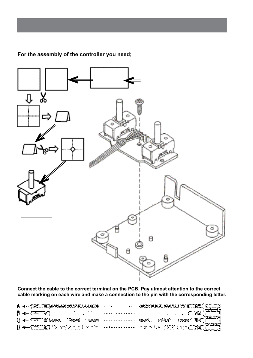
For the assembly of the controller you need;
4. ASSEMBLY INSTRUCTIONS SOCCER ROBOT
Connect the cable to the correct terminal on the PCB. Pay utmost attention to the correct
cable marking on each wire and make a connection to the pin with the corresponding letter.
Controller assembly
WARNING:
Do NOT put the batteries into the
battery holder yet. Wait until the
robot is completely assembled.
When you create a short cut and
the batteries are already placed,
you can start a fire or get hurt by
the extreme heat of the
batteries.
1 pc. Felt
1 pc. Switch PCB
1 pc. Cable set
1 pc. Controller bottom
1 pc. Tapping screw 2.6x6mm
To make a felt cover for the switches,
please follow the arrows.
Attach the PCB to the controller bottom
with the tapping screw 2.6x6
- 8 -
Page 9

Final assembly of the Controller :
For the final controller assembly you need;
Install the battery bottom with the
4 tapping screws M2.6 x 6mm.
Attach the sticker
Finally, we install the
battery holder with the
2 tapping screws
M2.3 x 8mm
The completed
CONTROLLER
Connect the battery wires to the correct
+ and - terminals on the PCB (see drawing)
and PCB marking.
Black = - (Blk)
Red = + (Red)
Assemble the controller as shown on the pictures blow
and in numerical order
:
1 pc. Assembled controller bottom
1 pc. Battery holder
2 pcs. Tapping screw 2.3x8mm
1 pc. Controller top
1 pc. Sticker
4 pc. Tapping screw 2.6x6mm
IMPORTANT
Be sure that the cables are guided
through the correct holes.
Motor cable
Battery cable
- 9 -
Page 10
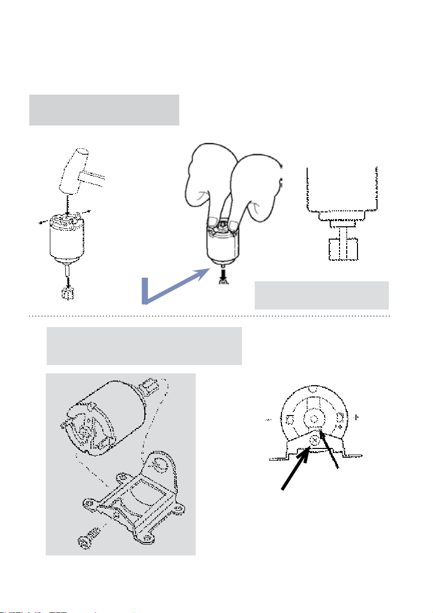
Assembly of the motors:
To assemble the motors you need;
2 pcs. Motor
2 pcs. Pinion gear
2 pcs. Motor holder
2 pcs. Tapping screw M2.3 x 5mm
Assemble the gear to the motor shaft as
shown on the picture below.
MAKE 2 SETS!
Hit slightly with the hammer,
do not hit the terminals!
OR BETTER:
Push the gear on the shaft
with your hands.
Be careful not to damage the gear or motor shaft.
When you use a hammer, be very gentle and put a piece
of wood between hammer and gear or better use a plastic
hammer. Best way is to push the gear on the shaft with your
hands.
Attach the motors to the motor holder with a tapping
screw M2.3 x 5 mm.
MAKE 2 SETS!
The shaft must be fully pushed into
the gear !
- 10 -
Flat part is faced down
Be sure the motor is fixed
properly with the 2.3 x 5 mm
tapping screw.
Page 11

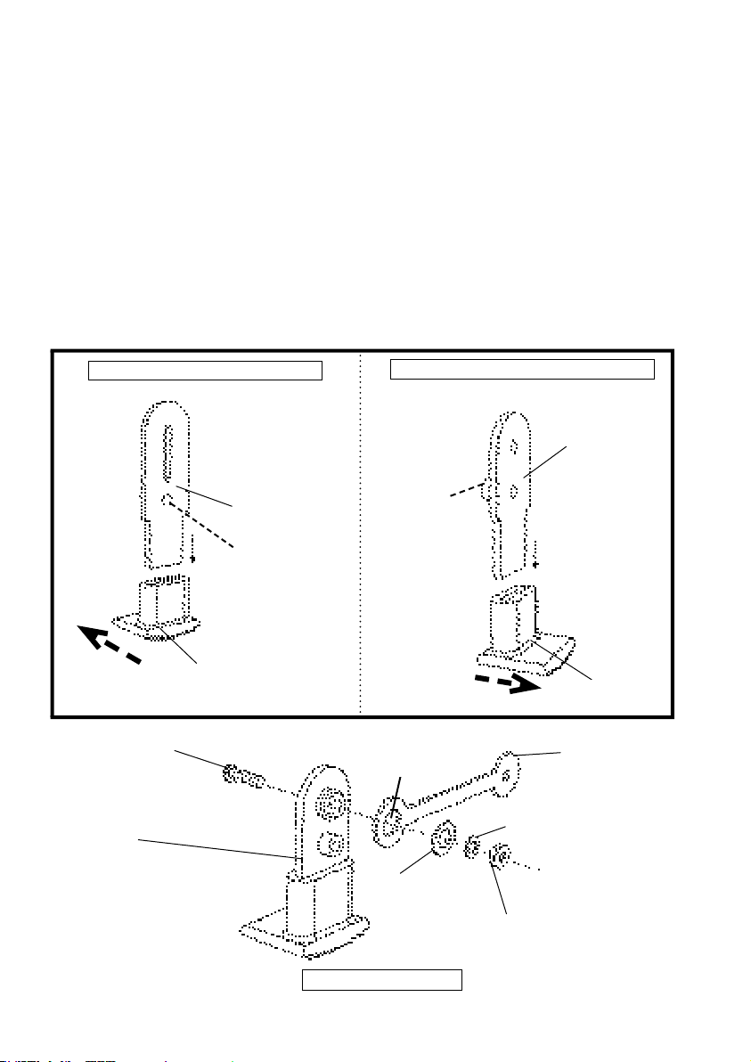
Assembly of the side panels:
For the assembly of the side panels you need;
ATTENTION
Screw the lock nuts real tight!
Keep the lock nut in position by holding it with a plier
or a well-fitting spanner
Shaft
3x22mm
Screw long M3x20
2 pcs. Side panel L&R
2 pcs. Gear with boss
2 pcs. Crank
2 pcs. Shaft 3x22mm
2 pcs. Spacer 5mm
2 pcs. Screw shaft (thick)
2 pcs. Screw shaft (thin)
2 pcs. Lock nut
2 pcs. Screw long M3x20
4 pcs. Nut M2
Make two sets
Crank
Crank
Spacer 5mm
Shaft
3x22mm
Crank
First please read page 5 how to screw a lock nut.
Make 2 sets.
Assemble the left panel in the
same way as the right panel.
Nut
M2
The boss
is on the
other site
Big hole
Gear with boss
Lock nut
Screw shaft thick
Screw shaft thin
- 11 -
Page 12

Assembly of the gears:
For the assembly of the gears you need;
Asssemble the gears and motor as shown on the
drawing below.
Assemble in numerical order.
4 pcs. Screw M2 x 5mm
2 pcs. Assembled side panels L & R
2 pcs. Flat spur gear with pinion
2 pcs. Crown gear with pinion
8 pcs. Screw M2
8 pcs. Nut M2
8 pcs. Spring washer M2
2 pcs. Screw shaft long
2 pcs. Washer M2
2 pcs. Nut M2
Washer M2
Screw shaft
long
Nut M2
4 pcs. Spring washer
Flat spur gear
Crown gear
4 pcs. Nut M2
Assemble the left and right side in the same way
MOTOR
- 12 -
Page 13

Final side pannel assembly:
For the final side panel assembly you need;
3 pcs. Screw M2 x 32mm
Spacer 10mm
2 pcs. Spacer 25mm
Kicker
2 pcs. Assembled side panel L and R
3 pcs. Screw M3 x 32mm
5 pcs. Nut M3
2 pcs. Spacer 25mm
2 pcs. Spacer 10mm
1 pcs. Cable holder
1 pcs. Kicker
Cable holder
2 pcs. Nut M3
Spacer 10mm
Attach the two side
panels together.
After this step we will name this assembled part the CHASSIS.
- 13 -
Top view
3 pcs. Nut M3
Page 14
Leg assembly:
For the leg assembly you need;
Assemble the parts as shown on the drawings below:
6 pcs. Rubber feet
4 pcs. Leg short (front and back)
2 pcs. Leg long (middle)
4 pcs. Screw M3 x 10mm
4 pcs. Nut M3
4 pcs. Spring washer M3
4 pcs. Washer M3
4 pcs. Joint strip
Assemble 2 middle legs:
!
Screw M3
Front and
rear leg
Middle leg
(long)
Boss on
other side
Rubber Feet
Make 4 sets in total (2 front & 2 rear):
Boss on
this side
!
Large hole !
Spring washer M3
Washer M3
Front and rear
legs
(short)
Rubber feet
Joint strip
Make 4 sets
- 14 -
Nut M3
Page 15

Assembly of the front legs:
Front leg
Shaft 85mm
Spacer 5mm
Joint strip
Collar
Spacer
10mm
Spacer 5mm
Spacer 10mm
Collar
Collar screw
Front leg
For the assembly of the front legs you need;
Assemble the front legs on the left side and right side as shown
on the drawing. Also notice the small detail-drawing!
The assembly of the front legs is
for the left and right side exactly
the same.
1 pc. Chassis
2 pcs. Assembled front leg
2 pcs. Shaft 85mm
2 pcs. Spacer 5mm
2 pcs. Spacer 10mm
2 pcs. Collar
- 15 -
Page 16

Assembly of the rear legs:
Shaft 85mm
Spacer 10mm
Joint strip
Spacer 5mm
Collar
Collar
For the assembly of the rear legs you need;
1 pc. Chassis
2 pcs. Assembled rear leg
1 pc. Shaft 85 mm
2 pcs. Spacer 10mm
2 pcs. Collar
Rear leg
- 16 -
Page 17

Assembly of the middle legs:
Assemble the middle legs to the left and right side as shown on the drawings:
THE COMPLETED
SOCCER
ROBOT!
Washer
Washer
Collar
Collar
For the assembly of the middle legs you need;
1 pc. Chassis
2 pcs. Middle leg
2 pcs. Washer M3
- 17 -
Page 18

5. FINAL ASSEMBLY
Wiring of the motors
IMPORTANT: Please check the correct marking on the wires!
Notice the correct polarity (+ & -) of the controller cable:
A = + Rear motor
B = - Rear motor
C = + Front motor
D = - Front motor
+
+
-
Battery installation
Insert the batteries into the battery holder.
Notice the correct polarity (+ & -) of the batteries.
6. TROUBLESHOOTING
Problem: Check:
The motors are not running.
No leg movement.
The robot movements do not correspond
with the controller
• Check the batteries, are they really full
• Check the battery polarity (+ and -).
• Check the wires on the switch PCB.
• Check the wires on the motors.
• Check the gears and especially the lock nuts
(tighten them a bit more or less).
• Check the side panels, all gears and their position
(rotate motor pinion by hand).
• Check all wire markings and connections
• Change motor wire + & - so they will rotate in reverse.
• Change motor wires from front motor to rear motor
Finally pass the wires
through the cable holder
- 18 -
Page 19

7. SOCCER ROBOT GAME
In this chapter we describe some soccer robot games you can play:
SOCCER FIELD
A great field for our game is a ping pong table (table
tennis table). Make some fences around it and make
goals for both sides. Now you can a game with 2
robots or when you have only 1 robot try to make as
many goals as you can in 5 minutes.
SOCCER GAME
First make teams with 1 or 2 players and shoot the ball in the opponents goal as often as
possible during a certain period of time.
SOCCER POOL GAME
For this you need about 10 table tennis balls. Try to shoot as many goals as possible in
5 minutes of time using all balls. You also can number the balls and try to make a the highest
score counting the numbers on the balls!
8. HOW DOES THE SOCCER ROBOT MOVE?
On the next page you find some background information about gears. Here we explain how the
soccer robot can walk with his six feet.
Crank Mechanism
Crank
Joint
strip
When the robots does not function well yet or when the gears do not have a good grip, please
check the troubleshooting table on page 18. Please check all assembly steps again.
When your robot still does not function well, just take it apart and assemble it again. Check and
double check all assembly steps by studying each drawing. This way you might find the problem.
The SOCCER ROBOT can walk because of the
presence of the crank. The crank converts a
rotational movement into a reciprocating movement.
The robot is constructed in a way that the front and
rear legs only make a forward and backward
movement.
The middle leg is designed to make a vertical slide
movement, the crank circular movement is directly
Leg
conveyed to the toe of the middle leg.
So when the middle leg goes up, the front and back
legs go backwards and the robot moves forward.
- 19 -
Page 20
9. INFORMATION ABOUT GEARS
The mechanics of the SOCCER ROBOT consists of two parts. The first part is the gear
box, which takes care that the power from the motor shaft is converted to the crank.
The second part is to convert the rotation of the crank into a movement of the feet.
The transmission of power
Gears, transmission belts, shaft, crank, chains: They all can transmit power.
In the soccer robot four gears transfer the motor power into the crank. Such a transmission is called a gear box. The power is transmitted by the teeth of the gears. At the
same time three conversions take place:
a. Change in rotating direction
b. Change in rotating speed
90º
c. Change in torque
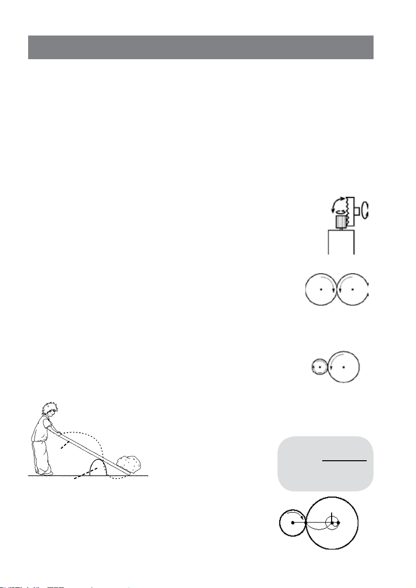
a. Change in rotating direction
When two gears are connected, there will be a change in rotation direction. One gear will rotate clockwise, the other gear will rotate counterclockwise.
Clockwise
Counter
clockwise
b. Change in rotation speed
The change in rotating speed depends on the relation of the teeth in
the gear. As an example we describe a gear with 10 teeth and a gear
with 40 teeth. When the first gear (10 teeth) makes a full rotation, the
second gear 40 (teeth) only makes a quarter of a rotation. So before the second gear
makes a full rotation, the first gear already makes four rotations. You may understand
that this effect also changes the rotating speed.
c. Change in torque
The torque can be seen as a lever construction with a
fulcrum. Imagine a person who lifts a stone with a lever.
10
Teeth
The person who lifts the lever
Lever
Fulcrum
A
B
must use more power when the
distance A gets shorter or when
the distance B gets longer.
Motor rotatio
Gear ratio =
Number of
last gear rotation
40
Teeth
This is about the same for gears. The power on the teeth
increases on the inner side of the gear. For that function
we are using spur gears.
- 20 -
Fulcrum
A
B
 Loading...