

RP6-JM03-61
RP6 SENSOR BOARD
RP6 Sensor board
©2013 AREXX Engineering and JM3 Engineering
www.arexx.com
AREXX Engineering & JM3 Engineering
Version: 1.20 Apr. 20, 2014 page: 1

Impressum
©2012 AREXX Engineering
Nervistraat 16
8013 RS Zwolle
The Netherlands
Tel.: +31 (0) 38 454 2028
Fax.: +31 (0) 38 452 4482
This manual is protected by the laws of
Copyright. It is forbidden to copy all or part
of the contents without prior written
authorization!
Product specifications and delivery contents
are subject to changes. The manual is
subject to changes without prior notice.
You can find free updates of this manual on
http://www.arexx.com/
“RP6 and AREXX” are registered trademarks from AREXX Engineering.
All other trademark are the property of their owners. We are not responsible for
the contents of external web pages that are mentioned in this manual!
Information about limited warranty and responsibility
The warranty granted by AREXX Engineering is limited to the replacement or repair of the
Module and its accessories within the legal warranty period if the default has arisen from
production errors such as mechanical damage or missing or wrong assembly of electronic
components except for all components that are connected via plugs/sockets.
The warranty does not apply directly or indirectly to damages due to the use of the robot.
This excludes claims that fall under the legal prescription of product responsibility.
The warranty does not apply in case of irreversible changes (such as soldering of other
components, drilling of holes, etc.) of the module or its accessories or if the module is
damaged due to the disrespect of this manual!
It cannot be guaranteed that the supplied software will satisfy individual expectations or
will run completely error-free and without any interruption. Moreover the software can be
freely changed and is loaded into the unit by the user. Therefore the user carries the full
risk regarding the quality and performance of the unit including all software.
AREXX Engineering guarantees the functionality of the supplied application examples
provided the respect of the conditions specified in the data sheet. If the SAM-04-LAN or the
PC software turns out to be faulty or insufficient, the customer carries all costs for service,
repair or correction.
Please note the relevant license agreements on the CD-ROM!
The exclamation mark attracts the attention of the user to important
instructions that must be adhered to. If you make a mistake in this part, it
can lead eventually to the destruction of the robot or its accessories and
even endanger your health or that of your environment!
The "Information" symbol draws the attention to useful tips and tricks or
background information. It is not always essential to understand
everything but it is often very useful.
Symbols
The manual uses following symbols:
AREXX Engineering & JM3 Engineering
Version: 1.20 Apr. 20, 2014 page: 2

Safety recommendations
IMPORTANT:
Prior to using this robot arm for the first time, please read this manual thoroughly up to
the end! They explain the correct use and inform you about potential dangers! Moreover
they contain important information that might not be obvious for all users.
- Check the polarity of the batteries or power supply.
- Keep all products dry, when the product gets wet remove the power directly.
- Remove the batteries or power when you are not using the product for a longer period.
- Before taking the module into operation, always check it and its cables for damage.
- If you have reason to believe that the device can no longer be operated safely,
disconnect it immediately and make sure it is not unintentionally operated.
- Do not operate the module in rooms or under unfavourable conditions.
- This module is equipped with highly sensitive components. Electronic components are
very sensitive to static electricity discharge. Only touch the module by the edges and
avoid direct contact with the components on the circuit board.
Normal use
This module is developed to use with robots, which allows you to determine basic behaviour patterns and
reactions of the robot to external influences yourself.
The module was developed as an experimental platform for all electronic technicians with interest in robotics. In
practical tests, it visualises the influence and effects of software parameters as well as physical parameters via
the corresponding sensor technology. Any use other than that described above is not permitted.
The product is not a toy and should be kept out of reach of children under 14 years of age! It may only be used
in closed, dry indoor rooms. The product must not get damp or wet. Use other than that described above can
lead to damage to the product and may involve additional risks such as short circuits, fire, electrical shocks etc.
Content
Impressum 2
Safety recommendations 3
Robot configuration with the RP6 Sensor Board 4
Introduction 5
Manual 6
Circuit 19
PCB layout 23
AREXX Engineering & JM3 Engineering
Version: 1.20 Apr. 20, 2014 page: 3
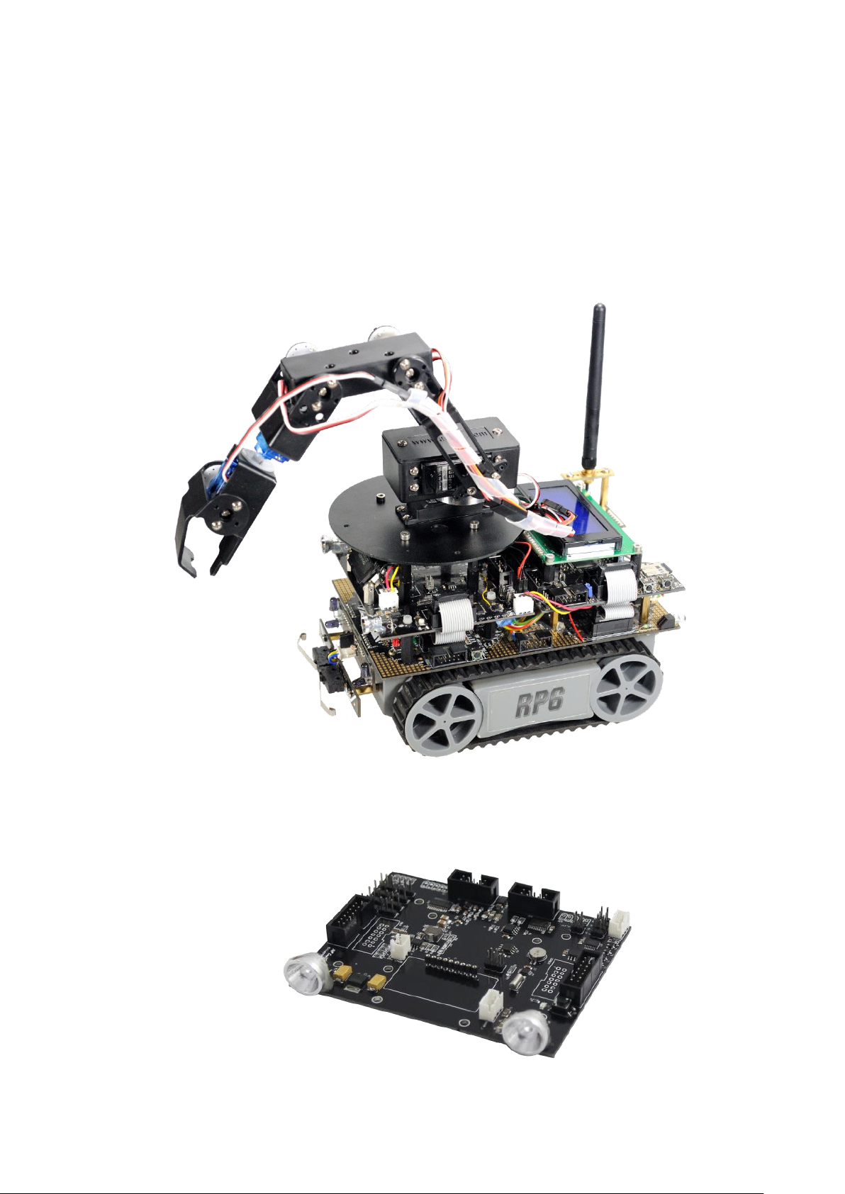
RP6V2/RP6WIFI – RP6_Sensor&I/O Board
Picture shows the RP6 with RP6WiFi Control board, the RP6_Sensor&I/O Board, Sharp Sensor
and a part of the AREXX Robot Arm RA2-HOBBY.
AREXX Engineering & JM3 Engineering
Version: 1.20 Apr. 20, 2014 page: 4

Introduction
What can I do with the RP6_Sensor&I/O Board?
The RP6_Sensor&I/O Board enables all versions of the RP6 Robots, but it is primarily designed for the
RP6V2 and RP6WIFI.
It provides the capabilities to measure signals and gives control over the sensor power consumption.
Together with the RP6V2 and RP6WIFI board you can send sensor data back to the ‘Command Center’
(PC Program) - e.g. compass heading, outside temperature, pitch & role angle. You can also command
new headings e.g. turn by 20°to left side.
The Servo Controller can drive up to 8 servos to command e.g. a Robot Arm (picture see front page),
which can be mounted on the IO Board. A switched regulator (5V 3 Amp.) can be switched on and off
by software.
The Sharp sensor measures distances very accurate, e.g. for autonomous route decision – or if it looks
downwards you can detect stairs or the table edge. There are two interfaces available, e.g. one at the
front and one at the rear.
The LED controller can control the brightness of the head LEDs and the Rear LED (if installed). Blinking
of the LEDs in case of turning to the right or left side is also easily possible.
The RTC can generate an interrupt waking up the RP6 at a programmed time from a sleep mode.
The yaw rate Gyro tells you if you try to turn into a direction, but you are blocked by obstacles - so you
can modify the strategy case by case turning into the other side
You can also add I2C based small modules (e.g. GPS) to the board which can be switched on/off by
software.
There are many, many new options you can develop for your RP6 – be creative!
Configuration and setup
The I/O board is designed to support best a master / slave configuration of the control board and the
base board, but it is not limited to.
This description provides guidance for the mater/slave configuration. The base board (SLAVE) controls
all drive relevant algorithms like ACS, move control, speed detection, etc. and gets the ‘move’ relevant
sensor input data like Gyro, Sharp-Front and -Rear. The control board (MASTER) gets input from the
sensors, e.g. compass heading and commands turns and speed via I2C to the base board. Commands
received via WIFI from the PC Remote Control Program will be executed to e.g. drive the servos or
switching the light ON or OFF. The RTC time and date can be set via WIFI as well.
From XBUS the board gets the 5V power supply and the I2C bus signal SDA and SCL to control all
functions. In addition, the extension board needs the ‘power-on’ signal from the base board (PWRON).
The analog signals from the Sharp sensor at the Front and Rear (if installed) and the gyro should be
measured by the base board directly. Therefore you need to add 4 wires to the base board (see
description further down in chapter 4). Alternatively, the Sharp Rear sensor analog signal (ADC4) goes
to the RP6WIFI control board (ADC connector PIN3), if this analog input should be used differently, you
can remove jumper J6 to disconnect the signal.
AREXX Engineering & JM3 Engineering
Version: 1.20 Apr. 20, 2014 page: 5

1.1. Board overview
3.3V regulator
I2C Hotswap
2 Digital-I/O
with GND pins
LED headlight
Distance sensor option
Sharp (front)
Temp. sensor
I2C Expansion modules
e.g. GPS I2C module
Gyro Yaw
LED driver
4 CH Power switch
RTC & recharge-able
battery -Attention – not
user serviceable!
Button & LED
compass
LED output
connectors
Sharp sensor
port (rear)
CAM I2C & PWR
VSS PIN – no short
protection!
ADC -
connector
I/O –
connector
3D Compass
Servo_PWR Input
Attention – no revers
polarity protection!
5.0V regulator
(servo supply)
Servo connectors
8 Ch. PWM OUT
‚Jumper‘
for interrupts
The RP6_Sensor&I/O Board provide multiple possibilities to add ‘sensors’ and actuators to the RP6.
AREXX Engineering & JM3 Engineering
Version: 1.20 Apr. 20, 2014 page: 6

On board there are:
- 2 x Sharp Sensor ports with power ON/OFF capability (front K5) / rear K3)
- 1 x I2C Expansion module port and 5V power ON/OFF capability MOSFET (K28)
- 8 x Servo output with separate power supply (5V / 3A)and ON/OFF capability
- 8 x PWM outputs
- 1 x CAM interface (CAM_IF) e.g. for a CMUcam3/CMUcam4 and power switch capability
The serial link can be attached to the RP6WIFI board (e.g. UART1).
The header provides an I2c bus interface (hot swap) which can be used for other module
extensions or the planned CAM module with I2C bus.
- I2C hot swap bus (allows to switch off I2C modules, if not needed and save power,
e.g. CAM and I2C extension)
- Temp sensor LM75BD (I2C)
- 1 button and LED (control via s/w)
- 3D Magnetometer / 3D Accelerometer for 3D compass function (I2C)
- Yaw Gyro (analog)
- Real Time Clock with date (rechargeable backup battery) I2C bus (can generate interrupt)
- LED driver I2C bus (smart functions)
2 LED headlights (controlled via LED driver)
2 LED for backlight of RP6 (K10)
Display illumination port (connector K7)
2 LED ports free (connector K2, K4)
- 2 x free Digital I/O lines (input can generate interrupt; connector I/O_EXT)
- Patchfield_1 to get access to I/O lines form Control board
- Patchfield_2 to get access to ADC lines form Control board
- Jumper J2, J3, J4, J5, J6 to disconnect Interrupt lines from connector pins
1.2. RP6 – Setup
The setup for the RP6 mainboard requires two additional steps:
Hint: The changes requiring basic soldering skills!
i. Soldering the header (1 x 8 Pins) into the mainboard.
ii. Connecting power to the Servo
The best is to use a separate battery for the servo power supply (SERVO_PWR), but it
works also from internal battery, if you make a connection with the Power Cable from the
Kit between the 8 Pin header on the mainboard and Servo Power plus on the
RP6_Sensor&I/O Board (JST XH connector).
iii. Then follow the steps from RP6V2 in chap. 1.3 (except Servo power supply)
AREXX Engineering & JM3 Engineering
Version: 1.20 Apr. 20, 2014 page: 7

1.3. RP6V2– Setup
ADC1
ADC0
1.3.1. Signals to be connected to the mainboard
The following signals need to be wired from the main board if you want to use the signals.
a. ADC0 -> PIN_1 USRBUS1 (Sharp front)
b. ADC1 -> PIN_2 USRBUS1 (Gyro)
c. ADC4 -> PIN_5 USRBUS1 (Sharp rear)
d. PWRON -> PIN_3 USRBUS1
The following options are possible:
i. Connecting the Sharp Front & Rear sensor to ADC0 – in this case you have to switch the
Sharps sensors alternately on (time –multiplex) and read out ADC0. The Gyro sensors will be
read from ADC1.
ii. The RP6V2 provides two connectors to connect analog signals ADC0 and ADC1 to the main
board (see picture below).
Make the wire connection from the USRBUS1 PIN_1 (SHARP_Front) and USRBUS1
PIN_5 (SHARP_Rear) to ADC0 header and the USRBUS1 PIN_2 (Gyro) to ADC1 header.
HINT: To connect both ADC signals from the Sharp sensors will only work, if they
are not powered on at the same time! If you want to use the Sharp sensors in a
different application mode then they should be connected to ADC inputs of the
control board.
iii. Alternatively you can solder wires on the back of the mainboard PCB from USRBUS1 to the
signal of the header – which looks more professional.
Hint: The changes requiring average soldering skills!
Do some soldering test before, if you doesn’t feel well enough with such changes.
It is important to use a soldering iron with a slim tip.
AREXX Engineering & JM3 Engineering
Version: 1.20 Apr. 20, 2014 page: 8

iv. The PWRON signal is the general enable/disable signal for the MOSFETS.
+UB and GND
Wire from Y3 to PWR
+UB
GND
Make the wire connection from the USRBUS1 PIN_3 to PWR signal on the main board.
HINT: To power a sensor you must select the specific sensor (see chap 3.2 Hardware
Register) and set the PWRON signal to logic 1.
1.4. Servo Power:
The best is to use a separate battery for the servo power supply (SERVO_PWR), but it works also from
internal battery, if you make a connection with the Power Cable from the Kit between the 8 Pin header
on the mainboard and Servo Power plus on the RP6-Sensor&I/O Board.
Hint: For the exact pin out of the 8 pin header please refer to the manual of the
RP6V2.
AREXX Engineering & JM3 Engineering
Version: 1.20 Apr. 20, 2014 page: 9

2 SW – Package for RP6_Sensor&I/O board working with the RP6WIFI
2.1 C++ and C-Source code support
Together with the RP6_Sensor&I/O board the door into the C++ word has been opened for the
RP6 Robot - and this in an easy way – no worry!
The C++ language is a superset of the C language or vice versa the C++ language is an extension
of the C-language, but more powerful and structured – more rigid in the compiler checks.
All in all it gives a better readable code and better protection against side effects of your software
design (e.g. enums and the use of name space definitions for the modules instead of tons of
#defines) - and of course with C++ you can combine C-code and Assembler-code.
Special advantages, will be given if you have multiple instances of e.g. a device driver like a UART
which saves memory. The developed code is also easier to port to a new system.
The used Extended Embedded C++ excluded by purpose the following C++ features, which
doesn’t make sense on an embedded system:
1.) RTTI
2.) Exceptions
Refer also to: http://www.iar.com/Products/IAR-Embedded-Workbench/Technology/Languagestandards/
The GCC makefile to compile your existing C-Code and the Libs from the RP6V2 or RP6WIFI
board and the C++ code from the Sensor & IO board with examples are included.
The software can be edited and complied with Visual Studio 2010 Express (free download at
Microsoft) – the makefile is included. Other editors can be used as well.
AREXX Engineering & JM3 Engineering
Version: 1.20 Apr. 20, 2014 page: 10

Here an example how to add in C-code in the C++ world (taken from the Demo Program):
Sensor
Address
LSM303 Accelerometer
0x32
LSM303 Magnetometer
0x3C
MAX7311AUG / TCA9555 IO-Expansion
0x40
TCA6507 LED Driver
0x8A
LM75 Temperature Sensor
0x90
DS1339U Real Time Clock
0xD0
PCA9685 PWM Controller
0x88
/**********************************************************************\
* IO Extension Demo Program
* main.cpp
* v 1.1.0
\**********************************************************************/
extern "C"
{
#include "RP6M256.h"
#include "RP6M256Lib.h"
#include "RP6M256uart.h"
#include "RP6I2CmasterTWI.h"
#include "Yourcode.h" <- include your C-code modules inside 'extern "C"'!
}
#include "ioExt.h" <- include your C++-code modules outside of 'extern "C"'!
. . . . // some code is not shown here
int main() __attribute__((noreturn));
int main()
{
initRP6M256(); <- function calls of C-code modules
I2CTWI_initMaster(400);
initLCD();
clearLCD();
// init RP6 Io Extension
ioExt::Initialize(); <- function calls of C++-code modules (with namespaces)
// set RTC test date and time in local structure
ioExt::rtc.setDay(07);
ioExt::rtc.setMonth(03);
ioExt::rtc.setYear(2013);
ioExt::rtc.setHour(23);
ioExt::rtc.setMinute(59);
ioExt::rtc.setSecond(55);
. . . // more code
2.2 I2C bus addresses
AREXX Engineering & JM3 Engineering
Version: 1.20 Apr. 20, 2014 page: 11

2.3 Hardware Control Register
Sensor/Item
I2C Address
Port #
I2C Module - ON/OFF
0x40
0.0
Sharp_Front_PWR - ON/OFF
0x40
0.1
Sharp_Rear_PWR - ON/OFF
0x40
0.2
Ready Signal I2C buffer (TCA4311A) - Input
0x40
0.3
LED Drive (TCA6507) - ENABLE
0x40
0.4
CAM PWR - ON/OFF
0x40
0.5
Gyro SLEEP/PWR (PD_2) - ON/OFF
0x40
0.6
Gyro TEST (ST_2) – ON/OFF
0x40
0.7
I2C OUT - ENABLE
0x40
1.0
I/O (IO_EXT_PIN1; free)
0x40
1.1
I/O (IO_EXT_PIN2; free)
0x40
1.2
Servo Output inverted (PCA9685) - ENABLE
0x40
1.3
Servo PWR - ON/OFF
0x40
1.4
Magnetometer data ready (LSM303) – DRYD (Input)
0x40
1.5
LED (D2) – ON/OFF
0x40
1.6
Switch (S1) input
0x40
1.7
Jumper
Description
populated
RTC Interrupt (DS1339) routed to INT3
J2
0R0 (SMD 0805)
Magnetometer INT1 (LSM303) to INT1
J3
0R0 (SMD 0805)
MAX7311 interrupt routed to INT2
J4
0R0 (SMD 0805)
Magnetometer INT2 (LSM303) to INT3
J5
0R0 (SMD 0805)
Sharp Rear (ADC4) routed to PIN3
of the ADC Connector
J6
0R0 (SMD 0805)
Hint: If you have more than one I2C Bus module or IC on the buffered I2c bus, then
always all modules must be powered on to read data!!!
AREXX Engineering & JM3 Engineering
Version: 1.20 Apr. 20, 2014 page: 12
2.4 IOExtDemo SW
Provides a base implementation to control the Sensor & IO board. A display 2 x 16 char will be
supported. The description is within the source code.
Source code files for both boards are included in the package (see src folder). The software can be
complied with Visual Studio 2010 Express (free download at Microsoft) – the makefile is included.
The makefile supports the existing C- code libs from the RP6V2 and RP6WIFI and combined this
with the C++ code from the sensor boards in an easy way.
Load the IoExtDemo.hex file into the RP6WIFI control board. The source code (included in the
package) for the demo software can be complied with Visual Studio 2010 Express (free download
at Microsoft) – the makefile is included.
The following messages will be shown on the LCD (Pressing SW1 RP6WIFI board will move to the
next screen):
1. StartScreen: RP6 IO Extension Demo Program
followed with Date (08.03.2013)
and Time (starting from 00:00:00)
2. Accelerometer: P (Pitch angle in 1/10 degree)
R (Pitch angle in 1/10 degree)
3. Compass: Hd (heading in degree)
Compass calibration (use SW2 on the RP6WIFI board):
1.) Press S1 after aligning the robot to North,
2.) Align to East followed and press S1
3.) Same for South and West to calibrate compass.
After calibration is completed the status LED should switch of.
HINT: Ferro-magnetic material will influence the result in heading
quality!!!
4. Temperatur: T (in degree C)
5. LED: SW2 toggles all LEDs ON/OFF
6. Servo: SW2 toggles between 2 PWM values
-45 deg and +45 deg
Keep in mid this is only a basic implementation to show how the IC shall be initialized and to
compute some data, e.g. the 2D-Compass application is included. The source code should be
adapted to your RP6V2 / RP6 software. Further documentation please refer to the source.
AREXX Engineering & JM3 Engineering
Version: 1.20 Apr. 20, 2014 page: 13

2.5 RP6-RC Demo SW (Remote Control)
At first start an
error message can
be displayed here,
because there is
no config- file.
This will be created
automatically.
If you click on ‘Use Keyboard (WASD)’ than the
control is via the keys W A S D.
Disabling will enable the joystick as control
automatically.
The RP6 Robot and the RP6WIFI board together enables you to control the RP6 Robot remotely so you can ‘drive’ the robot via a Joystick or WASD keys on the key pad - right, left, forward,
backward and turns. The joystick should be moved as straight as possible to the directions left,
right forward or backward.
The current version is a demonstration PC program and associated RP6 Base and WIFI hex-flies.
Other functions like sensor data transmission and Light ON/OFF can be added by the user (source
code will be made available).
Source code files for both boards are included in the package (see src folder). The software can be
complied with Visual Studio 2010 Express (free download at Microsoft) – the makefile is included.
The make file supports the existing c- code libs from the RP6V2 and RP6WIFI and combined this
with the C++ code from the sensor boards in an easy way.
2.5.1 Configuration and setup
2.5.1.1 RP6 Base
Load the ‘RP6Base_I2CSlave.hex’ file with the Robot Loader into the RP6v2.
2.5.1.2 RP6WIFI
Load the ‘rp6RcDemo.hex’ with the Robot Loader into the RP6.WIFI control board.
2.5.1.3 PC-Remote Program
Copy the folder ‘pc’ on your desktop, open the folder ‘pc’ and run the ‘RP6-RC.exe’ program.
You should see the following window:
The files EXE-file and the 2 DLL’s must be in the same folder!
AREXX Engineering & JM3 Engineering
Version: 1.20 Apr. 20, 2014 page: 14

Switch the RP6 ON and run the application, then type your RP6 IP into the Hostname field and
Your Robot IP !
Status message –
remote control active
after enabling the
remote control !
click on the connect button and click on the box to ‘Enable Remote Control’.
You should see the following:
After the connection has been accepted, you get some signals reported from the RP6, which
are:
1.) Depth signal (if a Sharp sensor in the front is installed)
2.) Speed of right and left chain (actual speed)
3.) Battery voltage
4.) ACS state information
5.) MoveState ( 1 == Remote Control)
In the command field (Send Command) you can type in commands which will be sent to the
RP6WIFI board.
Keep in mind, currently there is no command coded on the RP6WIFI board in this version to
the demonstrator program.
Optional there are status messages displayed on the LC Display is connected.
2.5.1.4 PC Requirements
PC with WINDOWS VISTA / 7 operation system
WIFI access; Robot WIFI IP assigned
Optional: Joystick – e.g. Logitech connected to the PC.
AREXX Engineering & JM3 Engineering
Version: 1.20 Apr. 20, 2014 page: 15
HINT: The Firewall Program can refuse the connection – please allow the
Robot IP in your network.
2.5.1.5 Robot Requirements
RP6 Robot with RP6WIFI Board
optional: RP6_Sensor&I/O Board, Sharp Sensor, display (min: 2 lines with
16 characters

3. Detailed descriptions of the integrated circuits see datasheets
- LM75BM Temp. Sensor
- LSM303DLHC Magnetometer and Accelerometer
- DS1339U33 RTC
- MAX7311AUG I/O digital
- TCA6507 LED Driver
- LY330ALH Gyro Yaw
- PCA9685 PWM Servo controller
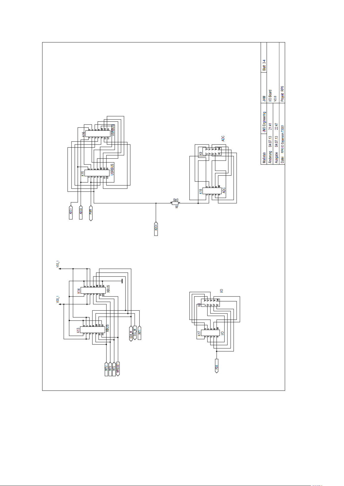
4. Connector PIN-OUT
4.1. Connectors to Board:
XBUS: VSS_1 = PIN 4, 6
VDD_1 = PIN 3, 5
GND = PIN 1, 2,
14
SDA = PIN 12
SCL = PIN 10
INT1 = PIN 8
INT2 = PIN 11
INT3 = PIN 9
MRESET = PIN 13
I/O (K17):
USRBUS: ADC0 = PIN 1 (Sharp front)
ADC1 = PIN 2 (Gyro)
ADC4 = PIN 5 (Sharp Rear)
PWR = PIN 3
ADC (K18): ADC4 = PIN 3
(Sharp rear -
alternative PIN)
PD5 = PIN 9 (I2C OUT -
Enable
alternatively)
Hint: The signal name PD5 on the Sensor Bord was derived from the Control M32
board. PIN 9 of the I/O header on the M256 Board is labeled as PB6
(IO_PWM/T0/T1).
The signal ADC4 on the Sensor Board was derived from the Control M32
board. PIN 3 of the ADC header on the M256 Board is labeled as ADC9
(ADC_IO2/CMP).
AREXX Engineering & JM3 Engineering
Version: 1.20 Apr. 20, 2014 page: 16

4.2. Connectors on Board:
K2: (LED)
PIN 1 = P2
PIN 2 = VDD_1
K3: (Sharp Rear)
PIN 1 = ADC4
PIN 2 = VDD_1
PIN 3 = Load (100 Ohm)
K4: (LED)
PIN 1 = P1
PIN 2 = VDD_1
K5: (Sharp Front)
PIN 1 = ADC0
PIN 2 = VDD_1
PIN 3 = Load (100 Ohm)
K7: (Display. Illumination)
PIN 1 = P0
PIN 2 = VDD_1
K10: (LED Out)
PIN 1 = P3
PIN 2 = P4
K28: (I2C)
PIN 1 = Load
PIN 2 = VDD_1
PIN 3 = SCLOUT
PIN 4 = SDAOUT
PIN 5 = SCL_M
PIN 6 = SDA_M
K12: (PWM OUT)
PIN 1 = PWM0
PIN 2 = PWM1
PIN 3 = PWM2
PIN 4 = PWM3
PIN 5 = PWM4
PIN 6 = PWM5
PIN 7 = PWM6
PIN 8 = PWM7
K6: (SERVO_1)
PIN 1 = PWM15
PIN 2 = Servo_PWR
PIN 3 = GND
K11: (SERVO_2)
PIN 1 = PWM14
PIN 2 = Servo_PWR
PIN 3 = GND
K29: (SERVO_4)
PIN 1 = PWM13
PIN 2 = Servo_PWR
PIN 3 = GND
K30: (SERVO_3)
PIN 1 = PWM12
PIN 2 = Servo_PWR
PIN 3 = GND
K31: (SERVO_6)
PIN 1 = PWM11
PIN 2 = Servo_PWR
PIN 3 = GND
K32: (SERVO_5)
PIN 1 = PWM10
PIN 2 = Servo_PWR
PIN 3 = GND
K33: (SERVO_8)
PIN 1 = PWM9
PIN 2 = Servo_PWR
PIN 3 = GND
K34: (SERVO_7)
PIN 1 = PWM8
PIN 2 = Servo_PWR
PIN 3 = GND
K19: (Dig-I/O)
PIN 1 = I/O1.2
PIN 2 = GND
PIN 3 = I/O1.1
PIN 4 = GND
M1; (I2C Module Interface):
PIN 1 = VDD_1
PIN 2 = SDLOUT
PIN 4 = SDAOUT
PIN 5 = LED
PIN 6 = Input button S1
PIN 9 = GND (switched)
AREXX Engineering & JM3 Engineering
Version: 1.20 Apr. 20, 2014 page: 17

4.3. Rechargeable Battery
The Battery will be recharges automatically while the IO Board is in use (RP6 is switched on).
Overloading is not possible.
Hint: You must enable the Trickle charger in the RTC (DS1339 – 2kOhm and Diode). Refer
to the source IOExtDemo Software and/or the datasheet of the DS1339!
Hint: There should be no need to replace this battery! Recharging will occure during
normal operation of the Robot. The data will be kept over several weeks.
5. Technical data
5.1. Supply voltage / current consumption (bus not active, no other connections rather than supply
voltage and GND).
VDD (PIN3, XBUS) = 5,0 V ± 2%
IDD = 15,00 mA ± 5,0mA
5.2. Servo Power Supply input voltage.
VSensor_PWR ≤ 10,0 V
ISensor_PWR ≤ 3,0 A average; peak load up to 5,0 A
depending on servo load
5.3. Gyro:
Vout = Vout(0) ± 10mV / dps ± 2%
Vout(0) = 2,5 V ± 2% (no motion)
Range = approx. 200dps max
5.4. Power switches:
Iout max = 0.5 A / continuous each channel / peak 1,0A
(5V regulator on base board might be limiting if all
4 channels are active at the same time.)
5.5. I2C Bus speed max. 400kHz
5.6. All other data according to IC data sheets (see chap. 3.)
AREXX Engineering & JM3 Engineering
Version: 1.20 Apr. 20, 2014 page: 18

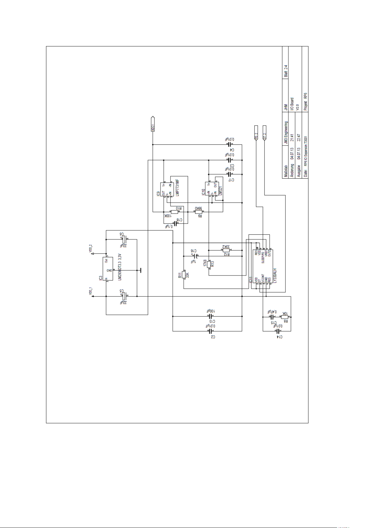
RP6 SENSOR BOARD CIRCUIT DIAGRAM
AREXX Engineering & JM3 Engineering
Version: 1.20 Apr. 20, 2014 page: 19
AREXX Engineering & JM3 Engineering
Version: 1.20 Apr. 20, 2014 page: 20
AREXX Engineering & JM3 Engineering
Version: 1.20 Apr. 20, 2014 page: 21

AREXX Engineering & JM3 Engineering
Version: 1.20 Apr. 20, 2014 page: 22

RP6 SENSOR BOARD PCB LAYOUT
AREXX Engineering & JM3 Engineering
Version: 1.20 Apr. 20, 2014 page: 23
 Loading...