

Page 1

Developed by JM³ Engineering
JM3-MARVIN-01
User Manual
(c) 2015-2017 AREXX Engineering und JM³ Engineering
The latest updates are available at jm3-engineering.com!
AREXX Engineering & JM³ Engineering
Version: 1.2.3
Marvin IoT Robot
www.arexx.com
March 26, 2017 Page: i
Page 2

Imprint
© 2016-2017 AREXX Engineering
Nevistraat 16
8013 RS Zwolle
The Netherlands
Tel.: +31 (0) 38 454 2028
Fax.: +31 (0) 38 452 4482
“Marvin” is licenced by and “iRP” is a registered trademark from “JM3 Engineering”. “AREXX” is a
registered trademark from AREXX Engineering. All other trademark are the property of their owners. We
are not responsible for the contents of external web pages that are mentioned in this manual!
Information about limited warranty and responsibility
The warranty granted by AREXX Engineering is limited to the replacement or repair of the Module and
its accessories within the legal warranty period if the default has arisen from production errors such as
mechanical damage or missing or wrong assembly of electronic components except for all components that
are connected via plugs/sockets.
The warranty does not apply directly or indirectly to damages due to the use of the robot. This excludes
claims that fall under the legal prescription of product responsibility.
As soon as you make irreversible changes (for example, soldering other components, drilling holes, etc.) on
the robot or its accessories, or the robot is damaged as a result of non-observance of these instructions will
void any warranty claim!
It cannot be guaranteed that the supplied software will satisfy individual expectations or will run completely
error-free and without any interruption. Moreover the software can be freely changed and is loaded into
the unit by the user. Therefore the user carries the full risk regarding the quality and performance of the
unit including all software. AREXX Engineering guarantees the functionality of the supplied application
examples provided the respect of the conditions specified in the data sheet. If the purchased hardware
or the PC software turns out to be faulty or insufficient, the customer carries all costs for service, repair or
correction. Please note the relevant license agreements on the SD-Card respectivly the Info-Box in browser!
Important! - Before using this robot for the first time, please read the operating instructions carefully! It
explains the correct handling and informs you about possible dangers. It also contains important information
that should not be known to all users.
This manual is protected by the laws of Copyright. It is
forbidden to copy all or part of the contents without prior written
authorization!
Product specifications and delivery contents are subject to
changes. The manual is subject to changes without prior notice.
You can find free updates of this manual on
http://www.arexx.com/
AREXX Engineering & JM³ Engineering
Version: 1.2.3
March 26, 2017 Page: ii
Page 3

Precautionary Notes
• Check the polarity of the voltage.
• Always keep the electronic equipment dry. In the case of moisture immediately remove the batteries or
the power supply to power down the device. This precaution is needed to keep it from short circuiting.
Drying is needed to avoid corrosion.
• Remove batteries before long-term storage respectively remove the power supply if the robot is not to be
used for some time.
• Before using the device always check the status of the equipment including the cabling.
• As soon as you think the device cannot be used in a secured way you must remove the power supply and
take precautions the device cannot be used unintentionally.
• Ask an expert if you feel unsafe or unsure in handling the device.
• Never operate the robot in unfavourable locations or inconvenient conditions.
• The equipment does contain highly sensitive parts. Electronic modules are quite sensitive to electrostatic
discharge (ESD). Only handle devices at the edges and avoid direct contact to the parts on the PCB.
Normal use
This product has been designed as an experimental tableau for all persons who feel interested in robotics.
The main goal for this platform is the experience to learn programming the device in C/C++-language. The
robot is not to be considered as a toy! The device is not suitable for children under 14 years of age.
The robot has been designed for indoor use. The device should not be exposed to moisture or damp. Please
be careful to avoid condensation vapor, which may generate moisture if you transport modules from a cold
environment into a warm room. Wait a while and do not activate modules until the devices have been
acclimatized to the room temperature.
Any other type of mode of operation as prescribed may cause damage and risks such as short circuit, fire and
shocks, etc. the robot is to be used in closed, dry environments. The device shall not be exposed to moisture
or water.
AREXX Engineering & JM³ Engineering
Version: 1.2.3
March 26, 2017 Page: iii
Page 4

Laser Security Notes Proximity Sensor
VL6180X 80/87 DocID026171 Rev 7
The VL6180X Proximitiy Sensor is equipped with a laser source and a laser control module. The output power of the
laser light source is designed and limited to always comply with the safety limits according for Class 1 Laser sources.
This also includes singular accidents according to IEC 60 825-1:2007. As long as the device is being operated within
the range and operating conditions as specified in the data sheets by ST Microelectronics the optical laser output power
will be restricted to the specified limits.
The optical laser output may never be raised and under no circumstances any optical lenses are allowed to be used for
focusing the light beam!
For security reasons we discourage to look into the laser light source.
Complies with 21 CFR 1040.10 and 1040.11 except for deviations pursuant to Laser Notice No.50, dated June 24, 2007.
AREXX Engineering & JM³ Engineering
Version: 1.2.3
March 26, 2017 Page: iv
Page 5

Contents
1 Introduction 2
2 Manual 4
2.1 Marvin robot hardware . . . . . . . . . . . . . . . . . . . . . . . . . . . . . . . . . . . . . . . . . . . . . . . . 4
2.2 Marvin robot equipment and accessories . . . . . . . . . . . . . . . . . . . . . . . . . . . . . . . . . . . . . . . 5
2.2.1 Features . . . . . . . . . . . . . . . . . . . . . . . . . . . . . . . . . . . . . . . . . . . . . . . . . . . 5
2.2.2 Detection range of the proximity-sensors . . . . . . . . . . . . . . . . . . . . . . . . . . . . . . . . . . 6
2.2.3 Installation of additional proximity sensors (rear) . . . . . . . . . . . . . . . . . . . . . . . . . . . . . . 7
2.3 Commissioning . . . . . . . . . . . . . . . . . . . . . . . . . . . . . . . . . . . . . . . . . . . . . . . . . . . . 7
2.3.1 Documentation and software . . . . . . . . . . . . . . . . . . . . . . . . . . . . . . . . . . . . . . . . 7
2.3.2 iRP WebIDE . . . . . . . . . . . . . . . . . . . . . . . . . . . . . . . . . . . . . . . . . . . . . . . . . 8
2.3.3 iRP connection with PC/Tablet . . . . . . . . . . . . . . . . . . . . . . . . . . . . . . . . . . . . . . . 9
2.3.4 Status LEDs . . . . . . . . . . . . . . . . . . . . . . . . . . . . . . . . . . . . . . . . . . . . . . . . . 12
2.3.5 System Display . . . . . . . . . . . . . . . . . . . . . . . . . . . . . . . . . . . . . . . . . . . . . . . 13
2.4 Calibration of sensors and set system time . . . . . . . . . . . . . . . . . . . . . . . . . . . . . . . . . . . . . . 13
2.4.1 RTC - set system time . . . . . . . . . . . . . . . . . . . . . . . . . . . . . . . . . . . . . . . . . . . . 14
2.4.2 Calibration of the 3D compass . . . . . . . . . . . . . . . . . . . . . . . . . . . . . . . . . . . . . . . 14
2.4.3 Calibration of the 3D gyroscope . . . . . . . . . . . . . . . . . . . . . . . . . . . . . . . . . . . . . . 15
2.4.4 Proximity sensors activation . . . . . . . . . . . . . . . . . . . . . . . . . . . . . . . . . . . . . . . . 16
2.4.5 Calibration of the proximity sensors . . . . . . . . . . . . . . . . . . . . . . . . . . . . . . . . . . . . 16
2.5 Command line interface (CLI) . . . . . . . . . . . . . . . . . . . . . . . . . . . . . . . . . . . . . . . . . . . . 18
3 Programming with iRP 20
3.1 Introduction in iRP . . . . . . . . . . . . . . . . . . . . . . . . . . . . . . . . . . . . . . . . . . . . . . . . . . 20
3.1.1 Basic operation . . . . . . . . . . . . . . . . . . . . . . . . . . . . . . . . . . . . . . . . . . . . . . . 20
3.1.2 iRP help . . . . . . . . . . . . . . . . . . . . . . . . . . . . . . . . . . . . . . . . . . . . . . . . . . . 22
3.1.3 My first program . . . . . . . . . . . . . . . . . . . . . . . . . . . . . . . . . . . . . . . . . . . . . . 22
3.1.4 Program execution . . . . . . . . . . . . . . . . . . . . . . . . . . . . . . . . . . . . . . . . . . . . . 22
3.1.5 Program load or saved . . . . . . . . . . . . . . . . . . . . . . . . . . . . . . . . . . . . . . . . . . . . 23
3.1.6 Program errors (Debugging) . . . . . . . . . . . . . . . . . . . . . . . . . . . . . . . . . . . . . . . . 23
3.1.7 Program code (source code) viewer . . . . . . . . . . . . . . . . . . . . . . . . . . . . . . . . . . . . . 24
4 JM3 Robot-Tool 2.0 25
4.1 Linux . . . . . . . . . . . . . . . . . . . . . . . . . . . . . . . . . . . . . . . . . . . . . . . . . . . . . . . . . 25
4.2 Mac OSX . . . . . . . . . . . . . . . . . . . . . . . . . . . . . . . . . . . . . . . . . . . . . . . . . . . . . . . 25
4.3 Windows 7 . . . . . . . . . . . . . . . . . . . . . . . . . . . . . . . . . . . . . . . . . . . . . . . . . . . . . . . 26
4.4 Load your own programs created under C/C++ . . . . . . . . . . . . . . . . . . . . . . . . . . . . . . . . . . . . 27
4.4.1 Upload (Marvin application) . . . . . . . . . . . . . . . . . . . . . . . . . . . . . . . . . . . . . . . . 27
4.4.2 Upgrade Firmware (Bootloader) . . . . . . . . . . . . . . . . . . . . . . . . . . . . . . . . . . . . . . 28
4.5 Terminal window . . . . . . . . . . . . . . . . . . . . . . . . . . . . . . . . . . . . . . . . . . . . . . . . . . . 29
4.6 Firmware and iRP Micro SD-Card update . . . . . . . . . . . . . . . . . . . . . . . . . . . . . . . . . . . . . . . 30
4.6.1 Micro SD-Card update (Ubuntu-Linux): . . . . . . . . . . . . . . . . . . . . . . . . . . . . . . . . . . 30
4.6.2 Micro SD-Card update (Linux - general): . . . . . . . . . . . . . . . . . . . . . . . . . . . . . . . . . . 30
4.6.3 Micro SD-Card update (Mac OSX): . . . . . . . . . . . . . . . . . . . . . . . . . . . . . . . . . . . . . 31
4.6.4 Micro SD-Card update (Windows OS): . . . . . . . . . . . . . . . . . . . . . . . . . . . . . . . . . . . 31
5 Option: C/C++ Software 32
5.1 Software package for Marvin . . . . . . . . . . . . . . . . . . . . . . . . . . . . . . . . . . . . . . . . . . . . . 32
v
Page 6

5.1.1 Toolchain . . . . . . . . . . . . . . . . . . . . . . . . . . . . . . . . . . . . . . . . . . . . . . . . . . 33
5.1.2 Software-Library . . . . . . . . . . . . . . . . . . . . . . . . . . . . . . . . . . . . . . . . . . . . . . 33
5.1.3 Marvin function buttons . . . . . . . . . . . . . . . . . . . . . . . . . . . . . . . . . . . . . . . . . . . 33
5.2 Demo software description . . . . . . . . . . . . . . . . . . . . . . . . . . . . . . . . . . . . . . . . . . . . . . 33
6 Technical data 34
6.1 Dimensions and weight . . . . . . . . . . . . . . . . . . . . . . . . . . . . . . . . . . . . . . . . . . . . . . . . 34
6.2 Power supply and power requirement . . . . . . . . . . . . . . . . . . . . . . . . . . . . . . . . . . . . . . . . . 34
6.3 Supply voltages experiment board . . . . . . . . . . . . . . . . . . . . . . . . . . . . . . . . . . . . . . . . . . . 34
6.4 Further information . . . . . . . . . . . . . . . . . . . . . . . . . . . . . . . . . . . . . . . . . . . . . . . . . . 34
7 Schematic details 35
7.1 Arduino Extension Board . . . . . . . . . . . . . . . . . . . . . . . . . . . . . . . . . . . . . . . . . . . . . . . 35
7.2 Pin mapping TM4C129EKCPDT . . . . . . . . . . . . . . . . . . . . . . . . . . . . . . . . . . . . . . . . . . . 37
7.3 PCB Print . . . . . . . . . . . . . . . . . . . . . . . . . . . . . . . . . . . . . . . . . . . . . . . . . . . . . . . 39
List of Figures 40
List of Tables 40
AREXX Engineering & JM³ Engineering
Version: 1.2.3
March 26, 2017 Page: vi
Page 7

Marvin the IoT Robot
Figure 0.1 Marvin Robot
Marvin - iRP WebIDE - for browsers on PC, Notebook and Tablet
Figure 0.2 Welcome-Screen
*1) *2)
Figure 0.3 Program-Screen
Figure 0.4 Remote Control and Status Display
*1) Apple iPAD or MacBook can store programs only on the robot, not on local disk.
*2) Firefox, Google Chrome (PC/Notebook/Samsung Galaxy Tab A) and Safari (iPad Pro/MacBook Air) are tested - Internet Explorer or Edge are not supported.
AREXX Engineering & JM³ Engineering
March 26, 2017 Page: 1
Version: 1.2.3
Page 8

1 Introduction
The JM3 IoT robot, called Marvin, impresses with its equipment and performance. Main components are the
TIVA TM C microcontroller with ARM Cortex-M4F and 512KByte Flash, 256KByte SRAM, 6KB
EEPROM, and the CC3100 WI-FI® Network Controller that meet the standards 802.11 b/g/n with up to
16Mbps data rate, multi-connection, TCP and UDP. Optimal adapted PCB antenna, infrastructure & ad-hoc
mode with a range >25m under normal conditions.
In addition, the Marvin is equipped with high-tech sensor technology, a 9D gyro / compass, several proximity
sensors which operate almost independently of the reflection characteristic of the obstacle surface. These
sensors can also measure the ambient brightness. A battery buffered real-time clock and the Arduino
compatible expansion header are also included. The header can be used for own hardware developments or
other existing Arduino Shields (software must be developed by themselves).
The powerful micro-gearbox motors with high-resolution odometry guarantee a high speed of the robot with
its rubber drive. The power is supplied by 6 standard AA or NiMH batteries.
A virtual display can be found in the browser (Firefox, Google Chrome, Safari) on a PC/Notebook, Mac or
Tablet. In addition, the Marvin robot can be remote controlled.
The graphical programming interface “Marvin - iRP” allows beginners to enter the world of programming in
a simple way - especially for students and kids, because it is not required to learn a programming
language first and no software development environment must be installed.
The C/C ++ option is for advanced programmers and experts. The programming under C/C++ with
FreeRTOS with a complete library of all hardware drivers (virtual display, button, UART, SPI, I2C, DMA,
ADC and timer etc.) is the base for own developments. The JM3 RobotTool for Linux and Windows allows
to upload programs (hex-code).
Marvin provides all the possibilities to program and control a robot, either way via the graphical iRP
interface or with C++.
AREXX Engineering & JM³ Engineering
Version: 1.2.3
March 26, 2017 Page: 2
Page 9

Accessories (not included)
• AA batteries (Ultra Power) or rechargeable batteries NiMH e.g. Ansmann HR06 Typ 2700
• Charger MW3310HC / 1 A Charging current setting
• USB-Kabel (Micro-B / Type A)
Sensor module extensions:
Extension Board (Arduino compatible, iRP programable)
• Interface with socket prepared for barometer or GPS module
• For your own hardware extensions
AREXX Engineering & JM³ Engineering
Version: 1.2.3
March 26, 2017 Page: 3
Page 10

2 Manual
Proxi-Sensors
Micro-SD Card
USB Interface
Motor-Driver
Odometer
Arduino Ext.
Shield header
Power Supply
5.0 V und 3.3 V
TivaC 1294
WiFi Subsystem
9D Sensor
Battery-Holder
6 x AA
Proxi-Sensors
(optional)
Button
Main-Switch
Charge-Plug
(for rechargable batteries)
2.1 Marvin robot hardware
Hint: The best thing to handle the Marvin robot is to grab it on the battery
Figure 2.1 Marvin robot hardware
compartment or on the chains. In addition, it should be avoided to touch directly
to the electronics (microcontrollers, etc.) as precaution agaist electrostatic
discharge (ESD!).
AREXX Engineering & JM³ Engineering
Version: 1.2.3
March 26, 2017 Page: 4
Page 11

2.2 Marvin robot equipment and accessories
2.2.1 Features
The IoT robot provides many new possibilities:
• TIVA TM C- mikro controller ARM Cortex-M4F Core (Floating Point) with 512KByte Flash,
256KByte SRAM, 6KB EEPROM, CC3100 WI-FI® 802.11 b/g/n – up to 16 Mbps, optimized PCB
antenna, Infrastructur- and Ad-Hoc Mode, Flash-ROM 8Mbit
• Virtual display on PC or Tablet-PC.
• 3x Proximity / Ambient Light Sensor (Time of Flight) in front at the center
– right and left.
– optional (retrofitted): 3 x rear (right, center, left)
• 9D - Gyro and compass sensor
• RTC with backup battery (recharging during operation)
• 1 x RGB status LED
• Status LEDs for Wi-Fi®
• 2 x LEDs USB (Rx, Tx)
• 2 x headlights (white) and 2x backlights (red)
• USB programming / Wi-Fi configuration (Micro USB connector)
• Micro SD-Card reader
• SMD button
• Arduino expansion plug - separate UART, SPI, I2C; 6 ADC, up to 8 GPIOs
• Interrupt capable, up to 4 PWM channels for servos
• 6 Cell power supply for AA batteries or rechargeable batteries for long operating times
• Slide switch and AUX battery input
• Switching regulator for high efficiency of the power supply
• Powerful micro-transmission motors with high-resolution odometry for high speed
• Rubber chain drive
• Application examples for Marvin iRP and remote control via Firefox or Google Chrome browser
(PC, notebook or tablet)
• Robot programming tool (supports all AREXX robots) and USB drivers for Linux and Windows 7
• C++ Software Development Pack (GCC ARM Compiler (Linux), C++ Software Library, Application
Examples)
• Micro SD card (robot documentation, iRP software and firmware: RobotTool, sample programs)
AREXX Engineering & JM³ Engineering
Version: 1.2.3
March 26, 2017 Page: 5
Page 12

2.2.2 Detection range of the proximity-sensors
The sensors have a detection range (FoV) of 25° and a range of approx. 30 cm. Distances below 10 cm are
displayed as zero. This ensures that the robot can avoid the obstacles without having to go backwards.
The two external sensors are twisted at +15° or -15° to the robot zero axis to achieve a wider angle of
detection. The representation of the resulting detection range shows a slight overlap of the individual sensors.
This ensures that all obstacles in the travel path are recognized.
The picture also applies to the optional rear sensors.
FoV Proximity sensors (Representation of all three sensors):
Figure 2.2 Field of View of the proximity sensors
AREXX Engineering & JM³ Engineering
Version: 1.2.3
March 26, 2017 Page: 6
Page 13

2.2.3 Installation of additional proximity sensors (rear)
The sensors have a pitch of 1.27mm - half as much as usual. Therefore you should have a soldering iron with
a fine tip and a power of approx. 50 W power.
Pay attention to the vertical position of the sensors and do not make them stand out. It is recommended to
first solder only one pin, then align the sensor and then solder all other pins. The details on activating the
sensors can be found in subsection 2.4.4.
Hint: Don’t forget to activate the new sensors by software!
Figure 2.3 Marvin with rear proximity sensors
Hint: It is best to exercise soldering on a PCB before - be economical with the solder.
Too much solder can cause shorts between the PINs!
2.3 Commissioning
2.3.1 Documentation and software
The complete documentation and the Marvin-iRP Web IDE software can be found on the enclosed Micro SD
card. It can be downloaded via the Marvin web interface and is then in the corresponding folder for
downloads of the computer.
The SD card uses the ext4 file system known from Linux and can not be read by Windows PCs or MacBooks
without special support programs. Any updates are distributed via disk images that are written to the Micro
SD card with a helper program. For this purpose a suitable micro SD card adapter is included on USB.
AREXX Engineering & JM³ Engineering
Version: 1.2.3
March 26, 2017 Page: 7
Page 14

Hint: In the delivery condition, the robot is set to the WiFi AdHoc mode so that it can
communicate directly with a PC with a Wifi interface (Notebook, T-Tablet, etc.).
There are a variety of micro SD cards that have different characteristics
and are available in Marvin may not work properly. SD-XC cards as well as
SanDisk Ultra cards are generally not supported!
Marvin software updates consist of the disk image with the iRP software.
It also contains the appropriate firmware (hex-file).
The versions of iRP software version and firmware version are always the same!
2.3.2 iRP WebIDE
The web interface software and the Marvin documentation are already on the enclosed Micro SD card. If the
micro SD card is not already inserted in the robot, please do so carefully now.
Figure 2.4 Marvin with inserted SD Karte
Hint: The Micro SD card usually does not have to be removed from the robot. It is
protected so that it is protected from damage. However, you should not touch
the robot so the Micro SD card is damaged!
AREXX Engineering & JM³ Engineering
Version: 1.2.3
March 26, 2017 Page: 8
Page 15

2.3.3 iRP connection with PC/Tablet
There are generally two different operating modes like the Marvin robot can be connected to the
PC/Notebook via WiFi:
• WiFi - Infrastructure mode: Connect Marvin to a network (WiFi router or access point)
• WiFi - AdHoc Mode: here you can connect the Marvin directly to the notebook or tablet PC.
– SSID: Marvin
– IP: 192.168.1.1
– Password: IoT-Robot
Hint: The password is case-sensitive!
Only in the AdHoc Mode is the SSID of the Marvin robot visible, since in
infratructure mode the Marvin connects to your router which has its own SSID.
Please delete the browser cache if the iRP screen is not loaded correctly!
2.3.3.1 WiFi - AdHoc mode
This mode is set when the robot is delivered. It provides the fastest way to program or control the robot.
To connect the robot to the PC / notebook, perform the following steps:
1. Switch on PC / Notebook with WiFi interface
2. Turn on the robot - the green WiFi status LED is lit.
3. Search for wireless networks on the PC / Notebook in the WiFi menu - here you should find the SSID
“Marvin”.
4. Pair the robot with the PC by entering the password and activate the connection.
5. Open the browser and enter the IP 192.168.1.1. You should see Figure 2.5 in the browser.
That’s it - you can now familiarize yourself with the menu and load and run a first small program!
6. Load the sample program “running lights”
7. You should now see the status LED glowing in different colors changing every 1sec.
AREXX Engineering & JM³ Engineering
Version: 1.2.3
March 26, 2017 Page: 9
Page 16

2.3.3.2 WiFi - Infrastruktur mode
This mode must first be configured on the robot with the JM3 Robot Tool and logged on to the WiFi router.
The Marvin supports DHCP and an IP address is automatically assigned.
Hint: If necessary, change the firewall settings so that the Marvin robot can connect
to the network!
Please delete the browser cache if the iRP screen is not loaded properly!
Here is the process for conversion to infrastructure mode:
1. Install the JM3 Robot Tool (installation - see chapter 4)
2. Connect the robot to the computer (Micro USB cable)
3. Open the Robot Tool, turn on the robot, and connect.
4. Proceed as follows:
a) Connect robot via USB
b) Change to terminal window (tab)
c) Send the following commands to the robot:
• wlan DEFAULT - “Enter”
• Turn the robot OFF and ON when it is displayed in the window
• wlan STA addprofile “SSID of your router” “password of your router” - “Enter”
Hint: Please note that the terminal history should be switched
off when the “addprofile” command is sent.
Otherwise, your password will be stored in plain text on
the PC!!!
For more information on the commands and how to
enter spaces, see section 2.5
• wlan STA MODE - “Enter”
• Turn the robot OFF and ON when it is displayed in the window
d) Check the assigned IP address (DHCP router) for the Marvin robot
• wlan getIP - “Enter”
The current IP address is now displayed in the terminal window.
AREXX Engineering & JM³ Engineering
Version: 1.2.3
March 26, 2017 Page: 10
Page 17

5. Then open the browser and enter the IP address, for example: 192.168.1.120
You should see Figure 2.5 in the browser.
That’s it - you can now familiarize yourself with the menu and load and run a first small program!
6. Load the sample program “running lights”
7. You should now see the status LED light up in different colors changing every 1 sec.
Figure 2.5 Marvin WebIDE Welcomescreen
AREXX Engineering & JM³ Engineering
Version: 1.2.3
March 26, 2017 Page: 11
Page 18

2.3.4 Status LEDs
To the status display of the robot (RGB-LED):
• blue - normal function
• Purple (blinking) - battery voltage low
• Yellow - no SD card or function impairment,
Notes on USB Interface.
• green - busy (SD recovery)
• blue/green (blinking) - no firmware
• yellow/red (blinking) - firmware programming
• red - functional malfunction - please turn robot On and Off
There are also three LEDs to display the status of the WIFI subsystem:
• red - Connection problem with WiFi network
• yellow (blinking) - transmitting data
• yellow (permanent) - WiFi connection stuck
• green - connected to WiFi network, this is always the case in AdHoc mode and
is independent of the HTTP connection.
AREXX Engineering & JM³ Engineering
Version: 1.2.3
March 26, 2017 Page: 12
Page 19

2.3.5 System Display
The key system status of the robot will be displayed in the “System Display”:
The System Display shows the following elements (Figure 2.6):
• Date and Time: - system date and time
• Battery - battery voltage
• Orientierung (Orientation) - compass heading (H:), pitch angle (P:), roll angle (R:)
• Proximity sensors (L/M/R) - distances left, mid, right
• Brightness sensors (L/M/R) - brightness left, mid, right
• Gyro sensor - angular turn rate in roll-axis (R:), pitch-axis (P:), yaw-axis (Y:)
Figure 2.6 System Display
2.4 Calibration of sensors and set system time
The Marvin robot supports the calibration of compass, gyro (rotational speed sensor) and distance sensors.
These functions are initiated in the Remote Control and Display window (see also subsection 3.1.1) with the
specific command buttons or via the command line interface (Figure 2.7). In addition, the real-time clock of
the robot can be synchronized with the system time of the PC/Notebook.
Hint: Calibration is usually only required once, and all recorded calibration data are
stored in the robot.
Figure 2.7 Command line interface
AREXX Engineering & JM³ Engineering
Version: 1.2.3
March 26, 2017 Page: 13
Page 20

2.4.1 RTC - set system time
Setting the real time clock in the Marvin robot is initiated by pressing the “Set RTC” button. This completes
the setting of the clock.
Hint: The time now also continues with Marvin switched off for several months. The
battery is recharged by switching on the robot.
2.4.2 Calibration of the 3D compass
The procedure for calibrating the 3D compass is described below. The alignment to NWSE
is automatically detected. A key must only be pressed or a command executed to start/stop.
Hint: The references to the sky direction facilitate a complete calibration - but are not
absolutely necessary. It is important to go through a complete circle!
2.4.2.1 Step 1 - preparation
Turn on the Marvin robot and connect the robot to the web interface in the browser. Take a compass and
determine the directions for north, east, south and west - remember the points.
Hint: You can skip this step if no compass is availble. Important is to cover the full
circle.
2.4.2.2 Step 2 - calibration mode on
Go to the remote control and display page and click the button “Calibrate compass”.
In the picture you see the imaginary axes related to the Marvin. The x-axis is red, the y-axis is green and the
z-axis is blue. Yellow is the inclination vector whose angle is not exactly known and depends on the location
on the earth. If the inclination vector and the x-axis are on a line then it can expected to be the maximum of
the measured value. This is necessary for a good calibration.
2.4.2.3 Step 3 - process
• Hold the robot to the north and tilt it upwards by 90 ° and then down.
• Hold the robot approximately horizontally to the north and tilt it 90 ° to the left and then to the right.
AREXX Engineering & JM³ Engineering
Version: 1.2.3
March 26, 2017 Page: 14
Page 21

Figure 2.8 Cardinal points and inclination vector
• Repeat this for east, south and west, or a complete circle, if possible with intermediate values, which
increases accuracy.
Hint: Do not tilt the Marvin too quickly during calibration!
2.4.2.4 Step 4 - finalization of calibration
After completing the procedure, close the calibration mode by clicking on the corresponding button “Finalize
calibration” and check the result by aligning the robot with the corresponding and known direction of the sky.
2.4.3 Calibration of the 3D gyroscope
Calibrate the gyro by pressing the “Calibrate Gyro Offset” button. The button will now show “calibration -
please wait” - this is done until the process is finished.
Hint: The calibration runs independently. Of course, the robot must not be moved.
AREXX Engineering & JM³ Engineering
Version: 1.2.3
March 26, 2017 Page: 15
Page 22

2.4.4 Proximity sensors activation
The proximity sensors are activated or deactivated using the “conf” command. Details are in Table 2.1. For
example, to activate the sensor in the center at the rear, enter the following in the command line:
• conf add RM “Enter” and subsequently
• conf save RM “Enter”
This would have added the RM sensor (rear center) and saved the configuration permanently and the sensor
is ready for operation.
2.4.5 Calibration of the proximity sensors
The calibration of the distance sensors is described below. For this purpose, an iRP auxiliary program must
be executed and the measured values must be noted for each sensor.
In addition, you need a ruler with a length of 30 cm to 50 cm. The values are then written into the robot with
the command interface Figure 2.7 and stored there.
Hint: The calibration of the distance sensors is not absolutely necessary and provides
an option to get more accurate results.
Beginners should not do this.
2.4.5.1 Step 1 - preparation
Turn on the Marvin robot and connect the robot to the web interface in the browser.
• Place the ruler in front of the respective sensor, so that the imaginary line of sight of the sensor is
coincident with the ruler.
• Start the iRP program “Distance sensor calibration”.
• Go to the “remote control and display page”.
In the lower display Figure 2.9, the distance raw values are displayed:
• FM (Front Mid) 0 - 255
• FL (Front Left) 0 - 255
• FR (Front Right) 0 - 255
• RM (Rear Mid) 0 - 255
• RL (Rear Left) 0 - 255
• RR (Rear Right) 0 - 255
AREXX Engineering & JM³ Engineering
Version: 1.2.3
March 26, 2017 Page: 16
Page 23

Hint: You can use the white Marvin Box for distance measurement!
2.4.5.2 Step 2 - process
Now measure the respective minimum and maximum value of the detection range.
• To do this, approach the obstacle (Marvin Box) from approx. 35 cm until the raw value is set to a value
smaller than 255 in the display.
• Find the exact point and write the raw value and the measured distance at the ruler.
• Approach the Marvin with the obstacle (Marvin Box) further until the raw value no longer changes in
the display (minimum value).
• Find the exact point and write the raw value and the measured distance at the ruler.
Figure 2.9 iRP auxiliary program data on user screen
Enter the following in the command line:
• cal prox FM 23 135.0 300 170 “Enter”
In this example, the front mid sensor (FM) with the lower raw value of “23” and the measured distance
“13.5” together with the measured distance “300” and the upper raw value of “170” would be used for
calibration.
Hint: All distances must be entered in “mm”!
2.4.5.3 Step 3 - verfication
After performing the procedure the robot needs a power cycle to use the calibration data. Then check the
result for the left, right, and center position sensor. For:
• ca. 13 cm muss 0
• ca. 30 cm muss 30
• > 30 cm muss 255 are displayed.
AREXX Engineering & JM³ Engineering
Version: 1.2.3
March 26, 2017 Page: 17
Page 24

2.5 Command line interface (CLI)
Table 2.1 describes all commands with syntax that are available.
AREXX Engineering & JM³ Engineering
Version: 1.2.3
March 26, 2017 Page: 18
Page 25

Table 2.1 CLI Kommandos
Command Description
cal cmps activates/deactivates the compass calibration mode.
cal gyro [--state] calibrates Gyro offsets. If the parameter “–state” is specified, the
current progress is output.
cal prox “sensor”
calibrates sensor: FL/FM/FR/RL/RM/RR.
“xNear” “mmNear”
“xFar” “mmFar”
conf “cmd” “sensor” configures the proximity sensors: FL/FM/FR/RL/RM/RR.
Commands (cmd): “add” “del” “read” “save”
light “on/off” Toggles driver lights on/off.
setrtc “H_M_S_W_D_M_Y” Set RTC to system time.
wlan AP ssid “SSID” Set SSID in AdHoc mode to “SSID”.
wlan AP passwd “passwd” Set password in AdHoc mode to “passwd”.
wlan AP txpwr “pwr” Set transmit power in AdHoc mode to “pwr”.
“pwr” Is a number between 0 and 15. “0” is the maximum transmit
power. Maximum efficiency is reached at“pwr” = 4.
wlan AP channel “ch” Set WLAN channel in AdHoc mode.
“ch” is a number between 0 and 13.
“ch” = 0 for automatic channel selection.
wlan AP MODE Switches Marvin to AdHoc mode.
wlan STA addprofile
“SSID” “passwd”
Joins the network with the SSID “SSID” and the password
“passwd”. In the future, it will automatically try to connect to this
network.
wlan STA delprofile “ID” Deletes the WLAN profile with ID “ID”. The ID “-1” deletes all
profiles.
wlan STA txpwr “pwr” Set transmit power in Infrastruktur mode to “pwr”.
“pwr” is a number between 0 and 15. “0” is the maximum transmit
power. Maximum efficiency is reached at “pwr” = 4.
wlan STA ipcfg
“DHCP” | “IP” “mask”
Enabled in Infrastructure mode DHCP or sets a static IP address.
“IP”, “mask”, “gw” and “dns” are IPv4 addresses.
“gw” “dns”
wlan STA MODE Switches Marvin to Infrastructure mode.
wlan STA SCAN Scans for available WLAN networks.
wlan DEFAULT Resets the WLAN module to factory settings.
wlan getIP Returns the current IP address.
version Outputs firmware version number.
security updatekey
Copy HTTPS key from the SD card to the WiFi module.
“key.der”
security updatecert
Copy HTTPS certificate from the SD card to the WiFi module.
“cert.der”
security htpasswd
Set web server username and password.
“user:passwd”
The “security” commands are only available in C ++ mode under Linux
AREXX Engineering & JM³ Engineering
March 26, 2017 Page: 19
Version: 1.2.3
Page 26

3 Programming with iRP
Program-Menu
(Worksheet)
Help-Menu
(Light Bulb)
Language-Menu
Tabs
Link-Indicator
The graphical programming language Marvin - iRP is easy to learn and requires none previous knowledge of
a programming language like C/C++.
The various function blocks allow to create and execute programs on a logical level.
3.1 Introduction in iRP
3.1.1 Basic operation
The general handling of a PC and browser is a prerequisite.
The link indicator is located to the left of the language menu.
3.1.1.1 The language setting symbol
Figure 3.1 Marvin WebIDE Menu bar
• A green light indicates a good connection.
• A red light indicates a short-term interruption or use of the entire bandwidth for downloading
documents from the SD card.
• If there is a longer error, a pop-up message is displayed on the screen.
• You can easily set the language using the language selection field.
• In addition, you can see the “Zoom” and “Pan” buttons at the bottom right hand side.
AREXX Engineering & JM³ Engineering
Version: 1.2.3
March 26, 2017 Page: 20
Page 27
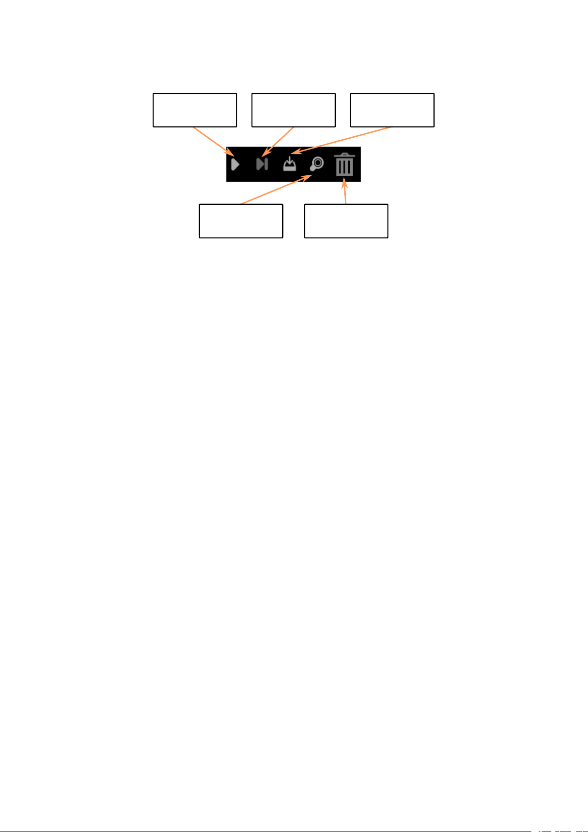
Single-Step
Zoom
Delete /
Trashcan
Download
Program
Start
program
Figure 3.2 Marvin WebIDE program buttons
Hint: Other languages such as Spanish, Italian, French and Chinese (simplified) are
supported. The online help is currently only available in German and English.
3.1.1.2 The light bulb symbol
• Find the help function for the iRP blocks with brief explanations.
• Notes on documentation and software.
• General notes about the program (info) and you can get the start screen displayed again.
3.1.1.3 The Worksheet symbol
• Here you can edit your programs, e.g. load, store etc. .
• Marvin SD card programs (menu to load and save)
• You can also select the iRP mode (Beginner, Intermediate, Expert) set to. The dark gray color indicates
the selection.
3.1.1.4 Remote control and display Tab
• Here are two displays, a remote control panel and a plotter area.
• The two virtual displays are divided into a fixed area where system values are displayed (for example,
the battery voltage) and a user area (user display).
In the user area you can display values from your program.
• In addition, you can make settings and send commands (section 2.5).
AREXX Engineering & JM³ Engineering
March 26, 2017 Page: 21
Version: 1.2.3
Page 28

3.1.1.5 Program Tab
• Here you can edit your programs, e.g. Load, save, etc. .
• You can also select the iRP mode (Beginner, Advanced, Expert) set to.
3.1.2 iRP help
A help function to the iRP blocks is always easily accessible in the browser.
• Click on the light bulb symbol (picture shown at the top left) or
• Click on the question mark on the right side of the screen.
The help sidebar scrolls to the currently used block automatically. (see Figure 3.3).
Figure 3.3 The Marvin WebIDE Helpbrowser
3.1.3 My first program
• A new program is simply merged together from the iRP blocks.
• If blocks are not logical matching, you can not attach them to the other block. In the example, the
block “real number” does not logically match to a “integer” (Figure 3.4).
3.1.4 Program execution
• A program can be “started” via the menu in the program tab or with the start button.
AREXX Engineering & JM³ Engineering
Version: 1.2.3
March 26, 2017 Page: 22
Page 29

Figure 3.4 Mismatch of block types in iRP
• Next to the “start button” is a “step button” (step by step execution of the program to the breakpoint),
the download button, the zoom function and the trashcan - for blocks which are no longer required.
3.1.5 Program load or saved
• Here you can load or save your programs. The location can be selected as usual.
• It is also interesting to insert already developed parts of the program. So you can build up a more
comprehensive program from different program modules - see example: “Drive a square with
compass”.
In this example there is a function included which does an averaging of the measurment values - this
could be a useful sub-function in other programs as well.
3.1.6 Program errors (Debugging)
If an error occurs during programming, an indication is given and the corresponding block is highlighted (see
Figure 3.5)
Hint: A very useful feature is the ability to set breakpoints to stop the program and
display an interesting value or state in the virtual display. This simplifies the
debugging, since the internal state of the software can be displayed easily!
AREXX Engineering & JM³ Engineering
Version: 1.2.3
March 26, 2017 Page: 23
Page 30

Figure 3.5 Beispiel für einen Compiler Fehler
3.1.7 Program code (source code) viewer
For further debugging, it may be helpful to look at the source text - but this is rather something for advanced
and experts. The selection is made by means of the program tab “source code” - in this case outputs as C++
source, C++ header and assembler are possible (Figure 3.6).
Figure 3.6 Example for generated C++ code
AREXX Engineering & JM³ Engineering
Version: 1.2.3
March 26, 2017 Page: 24
Page 31

4 JM3 Robot-Tool 2.0
4.1 Linux
• Copy the JM3 Robot Tool to a folder and run the program “launch_robotTool.sh”!
Hint: Further details see install.txt
• Click on the “Add Robot” icon - enter the name (freely selectable), the hostname and the USB port you
are using and go to the next step.
• Select the robot type, e.g. “Marvin”. The available USB port name can be looked up in the system
configuration - the USB port is usually “/dev/ttyACM0”. Just type in the correct USB port e.g.
“/dev/ttyACM0”. As interface type, select “UART” with a baud rate “0” (default).
• Click OK
• Click on “Add File” to select the hex-file with the new program. The search simply goes over the path
with “SelectFile”. Select the hex-file you want to load into the micro controller. As a further step select
the type, e.g. “Marvin”.
• Click OK.
• Select the robot and the program in the listed links.
• Click “Upload program” (at the top of the toolbar)
• Click “Save” (at the top of the toolbar), if you want to save the created robots and programs.
4.2 Mac OSX
• Copy the JM3 Robot Tool to a folder and run the program “robottool.app”.
• Click on the “Add Robot” icon - enter the name (freely selectable), the hostname and the USB port you
are using and go to the next step.
• Select the robot type, e.g. “Marvin”. The available USB port name can be looked up in the system
configuration - the USB port is usually “/dev/tty.usbmodem1421”. Just type in the correct USB port
e.g. “/dev/tty.usbmodem1421”. As interface type, select “UART” with a baud rate “0” (default).
• Click OK
• Click on “Add File” to select the hex-file with the new program. The search simply goes over the path
AREXX Engineering & JM³ Engineering
Version: 1.2.3
March 26, 2017 Page: 25
Page 32

with “SelectFile”. Select the hex-file you want to load into the micro controller. As a further step select
the type, e.g. “Marvin”.
• Click OK.
• Select the robot and the program in the listed links.
• Click “Upload program” (at the top of the toolbar)
• Click “Save” (at the top of the toolbar), if you want to save the created robots and programs.
4.3 Windows 7
• Copy the JM3 Robot Tool to a folder and run the file “robottool.exe”.
• Click on the “Add Robot” icon - enter the name (freely selectable), the hostname and the USB port you
are going to use.
• Select the robot type e.g. “Marvin”. The correct COM Port can be checked in the Device Manager -
often this is “COM3”. Just type in the correct COM port e.g. “COM3”. As interface select “UART”
and the baud rate should be set to “0” (default).
• Click OK
• Click on “Add File” to select the hex-file with the new program. The search simply goes over the path
with “SelectFile”. Select the hex-file you want to load into the micro controller. As a further step select
the type, e.g. “Marvin”.
• Click OK.
• Select the robot and the program in the lists on the left.
• Click “Upload program” (at the top of the toolbar)
• Click “Save” (at the top of the toolbar), if you want to save the created robots and programs.
AREXX Engineering & JM³ Engineering
Version: 1.2.3
March 26, 2017 Page: 26
Page 33

4.4 Load your own programs created under C/C++
To upload a self-written program (hex-file) into the micro-controller you must have installed the JM3
RobotTool before you can continue (Figure 4.1).
4.4.1 Upload (Marvin application)
• Start the JM3 Robot Tool It is assumed that the robot tool has already been prepared as described
above.
• Click on “Add File” to select the hex-file with the new program. The search simply goes over the path
with “SelectFile”. Select the hex-file you want to load into the micro controller. As a further step select
the type, e.g. “Marvin”.
• Click OK.
• Now select the robot entry from the list e.g. “Marvin” and the hex-file by clicking on it one by one
(highlighted light gray) and click “Upload”.
• Click on “Save” (at the top of the toolbar), if you want to save the created robots and programs.
AREXX Engineering & JM³ Engineering
Version: 1.2.3
March 26, 2017 Page: 27
Page 34

4.4.2 Upgrade Firmware (Bootloader)
The firmware of the Marvin robot also allows to flash the bootloader itself to a later version.
This requires the following steps.
• Select the new boot loader (hex-file) as described above.
• A click on “Upgrade Firmware” executes the update.
AREXX Engineering & JM³ Engineering
Version: 1.2.3
Figure 4.1 The JM3 Robot-Tool
March 26, 2017 Page: 28
Page 35

4.5 Terminal window
The terminal feature in the JM3 RobotTool allows serial data to be received and sent. It can also record data
and save it to a file. Various settings are available “Settings”:
• Connect to robot “Connect” allows data to be received.
• Disconnect connection to robot “Disconnect”.
• Send data to the robot “Right side - lower window” - commands can be entered here at any time.
Please set line-ending characters to “LF” (line feed).
• The program supports “undo” using the arrow keys (up and down) and “refresh” with F5.
Figure 4.2 The JM3 Robot-Tool - Terminal window
AREXX Engineering & JM³ Engineering
Version: 1.2.3
March 26, 2017 Page: 29
Page 36

4.6 Firmware and iRP Micro SD-Card update
In the following is a description of a software update process.
Firmware update (all Operating Systems):
The firmware update is performed with the JM3 Robot Tool. Details are described in chapter 4.
• Connect to the PC/Notebook using a USB cable (Mirco-B / TypeA).
• Start the JM3 Robot Tool and select the “Firmware.hex” file.
• Turn on the Marvin robot and connect to the PC/Notebook.
• Start it with a click on the “Upload icon”.
Hint: Firmware and iRP SD card image always belong together!
After an update always delete the browser cache!
4.6.1 Micro SD-Card update (Ubuntu-Linux):
The SD card update is started either by double-clicking on the image file (*.img), or by running an
“right-click” on the image file, and selecting “Writing drive image”. After this, a window “Restore drive
image” appears.
• Select your Micro SD card.
• Start the image update with “restore ...”
• Wait until the image has been copied completely.
• Please “eject” the drive.
4.6.2 Micro SD-Card update (Linux - general):
The SD card image is executed with the command “dd”.
• Insert the SD card with the USB adapter.
• Open a terminal window.
• Check the ID “/dev/sdX” of the SD card by running the command “sudo fdisk -l”.
• Note the ID of the SD card (it must have a size of approximately 2GBytes and contain exactly one
Linux partition).
• “Unmount” the SD card with the command “sudo umount /dev/sdX”.
• Start the image update with the command “sudo dd bs=1M if=myImage.img of=/dev/sdX”.
Attention: Use the correct filename and ID. Otherwise all data on
the computer can be destroyed!!!
AREXX Engineering & JM³ Engineering
Version: 1.2.3
March 26, 2017 Page: 30
Page 37

• Wait until the image has been copied completely.
• Please “eject” the drive.
4.6.3 Micro SD-Card update (Mac OSX):
The SD card image is executed with the command “dd”.
• Insert the SD card with the USB adapter.
• Open a terminal window.
• Check the ID “/dev/diskN” of the SD card by running the command “sudo diskutil list”.
• Note the ID of the SD card (it must have a size of approximately 2GBytes and contain exactly one
Linux partition).
• “Unmount” the SD card with the command “sudo diskutil unmountDisk /dev/diskN”.
• Start the image update with the command “sudo dd bs=1m if=myImage.img of=/dev/diskN”.
Attention: Use the correct filename and ID. Otherwise all data on
the computer can be destroyed!!!
• Wait until the image has been copied completely.
• Please “eject” the drive.
4.6.4 Micro SD-Card update (Windows OS):
The SD card image is performed with the “win32DiskImager” tool.
• Start the program and select the new SD card image.
• Start the image update.
• Wait until the image has been copied completely.
• Please eject drive ’.
AREXX Engineering & JM³ Engineering
Version: 1.2.3
March 26, 2017 Page: 31
Page 38

5 Option: C/C++ Software
The C++ programming language has emerged from the C language and represents an extension and
improvement of C.
All in all the more modern language which gives a better readability of the code and a much better protection
against side effects (e.g. enums / namespaces instead of often unclear #define instructions). Assembler and C
program parts can be easily combined with C++ code.
Special advantages and the reduction of program code in case of using multiple instances of h/w drivers can
be achieved - e.g. one instead of two UART drivers. Easier portability of the developed program code
represents a further advantage.
The used Extended Embedded C++ implementation does not allow the following C++ features which you
may know from PC programming - but which does not make sense for embedded Systems are:
• RTTI
• Exceptions
The libraries needed for the creation of own programs (h/w driver etc.) and a few application programs are
supplied with the package.
Hint: This option is for advanced users and experts.
C/C++ software development and the Realtime Operating System FreeRTOS
are not suitable for beginners!
The knowledge to deploy the entire Linux based toolchain and GCC compiler
including their configuration is required.
5.1 Software package for Marvin
The Marvin software package consists of the web interface software, the operating system (FreeRTOS) with
API functions and a library with all hardware drivers, e.g. the virtual display, ADC, timer, I2C, UART, LED
and keypad.
For further information and possibilities please read the descriptions of the modules and the corresponding
data sheets!
AREXX Engineering & JM³ Engineering
Version: 1.2.3
March 26, 2017 Page: 32
Page 39

5.1.1 Toolchain
As compiler, the GCC for ARM (arm-none-eabi-gcc) must be used under Linux. Additionally, the following
packages are required: make, newlib, arm-none-eabi-gcc and python. Any editor for the change of the source
code can be used.
The programming (s/w upload) is possible via the USB connection and the “JM3 Robot Tool”. Your program
can be loaded quickly and effectively into the TIVA C.
If you need full access to the microcontroller, you need a TIVA JTAG Interface (e.g., TM4C1294 “Connected
Launch Pad” EK-TM4C1294XL). In addition you have to solder the 8 PIN JTAG header (RM1.27) on the
PCB and a suitable connection cable must be build.
5.1.2 Software-Library
The software library also includes features such as compass, tilt measurement, real-time clock,
motor control and a user interface for the configuration of the WiFi interface.
The Web Interface can display various values on the virtual display in the browser.
All functions (blocks) known from iRP and others are available in the library. C++ code generated with iRP
can be exported and transferred to a new C++ project.
This also simplifies the transition from iRP to C++ code development.
5.1.3 Marvin function buttons
The Marvin function buttons in the Remote Control and Display tab Figure 5.1 can only be used with
your own C++ programs.
Figure 5.1 Marvin function buttons in Remote control and display tab
5.2 Demo software description
The demo programs of iRP can be exported and used in your own C++ programs. The iRP Web IDE -
“Remote control and display” can also be used as a virtual display.
AREXX Engineering & JM³ Engineering
Version: 1.2.3
March 26, 2017 Page: 33
Page 40

6 Technical data
6.1 Dimensions and weight
Width: 125 mm
Length: 148 mm
Height: 50 mm
Weight: 195 g (without batteries)
6.2 Power supply and power requirement
VCC = 8.4 V ± 5% => 6 AA cells
Hint: The absolute maximum is bei 10.0 V !!!
ICC
AVR
Hint: Battery lifetime:
= 160mA +40.0 mA / -20.0 mA => without Arduino Extension
ca. 5 h (Driving operation - engines at 50%)
ca. 10 h while programming with iRP
6.3 Supply voltages experiment board
VDD_3V3: Iout,max ≤ 50 mA
VDD_5V0: Iout,max ≤ 50 mA
VBat_M (VSS): Iout,max ≤ 200 mA
6.4 Further information
All other data can be taken from the following IC data sheets!
Controller: Texas Instruments TM4C1294KCPDT
Motor Driver: Texas Instruments DRV8833CPWP
9D-Sensor: ST Microelectronics LSM9DS1TR
Proxi-Sensor: ST Microelectronics VL6180X
AREXX Engineering & JM³ Engineering
Version: 1.2.3
March 26, 2017 Page: 34
Page 41

7 Schematic details
7.1 Arduino Extension Board
Arduino Shields are supported by the Hardware. All common interfaces such as I2C, SPI, UART ADC and
GPIOs or various timer outputs supoorting frequency or PWM generation e.g. for servo control. An input
capture function is available for measuring frequencies and duty cycles.
Table 7.1 Pin out Arduino compatible header
Pin 1 = IOREF
Pin 2 = RESET
Pin 3 = VDD_3V3
Pin 4 = VDD_5V0
Pin 5 = GND
Pin 6 = GND
Pin 7 = VSS (V_Bat)
Pin 8 = ADC_X5
Pin 9 = ADC_X4
Pin 10 = ADC_X3
Pin 11 = ADC_X2
Pin 12 = ADC_X1
Pin 13 = ADC_X0
Pin 14 = RX_X
Pin 15 = TX_X
Pin 16 = IO_0
Pin 17 = IO_1
Pin 18 = IO_2
Pin 19 = IO_3
Pin 20 = IO_4
Pin 21 = IO_5
Pin 22 = IO_6
Pin 23 = IO_7
Pin 24 = CS_X
Pin 25 = MOSI_X
Pin 26 = MISO_X
Pin 27 = SCK_X
Pin 28 = GND
Pin 29 = NC
Pin 30 = SDA_X
Pin 31 = SCL_X
AREXX Engineering & JM³ Engineering
Version: 1.2.3
March 26, 2017 Page: 35
Page 42

Figure 7.1 Marvin Arduino header - schematic
AREXX Engineering & JM³ Engineering
Version: 1.2.3
March 26, 2017 Page: 36
Page 43

7.2 Pin mapping TM4C129EKCPDT
Table 7.2 TM4C129EKCPDT Pin mapping
Pin Name Function Signal
1 PD0 SSI2DAT1 MISO_SD
2 PD1 SSI2DAT0 MOSI_SD
3 PD2 SSI2FSS CS_SD
4 PD3 SSI2CLK SCK_SD
5 PQ0 SSI3CLK WIFI_SPI_CLK
6 PQ1 SSI3FSS WIFI_SPI_CS
7 VDD
8 VDDA
9 VREFA+
10 GNDA
11 PQ2 SSI3DAT0 WIFI_SPI_MOSI
12 PE3 AIN0 ADC_X3
13 PE2 AIN1 ADC_X4
14 PE1 AIN2 ADC_X2
15 PE0 AIN3 ADC_X5
16 VDD
17 GND
18 PK0 GPIO SD_Present
19 PK1 GPIO INT_2_A/G
20 PK2 GPIO INT_1_A/G
21 PK3 GPIO NC
22 PC7 GPIO INT_M
23 PC6 GPIO DRDY_M
24 PC5 GPIO WIFI_RST
25 PC4 GPIO WIFI_HOST_INT
26 VDD
27 PQ3 SSI3DAT1 WIFI_SPI_MISO
28 VDD
29 PH0 GPIO PROX_RL_CS
30 PH1 GPIO PROX_RM_CS
31 PH2 GPIO PROX_RR_CS
32 PH3 GPIO NC
Pin Name Function Signal
33 PA0 U0RX RX_X
34 PA1 U0TX TX_X
35 PA2 SSI0CLK SCK_X
36 PA3 SSI0FSS CS_X
37 PA4 SSI0DAT0 MOSI_X
38 PA5 SSI0DAT1 MISO_X
39 VDD
40 PA6 GPIO REAR_R
41 PA7 GPIO REAR_L
42 PF0 M0PWM0 Motor_L - AINT1
43 PF1 M0PWM1 Motor_L - AINT2
44 PF2 M0PWM2 Motor_R - BIN1
45 PF3 M0PWM3 Motor_R - BIN2
46 PF4 M0FAULT0 nFault
47 VDD
48 GND
49 PG0 I2C1SCL SCL_PRX
50 PG1 I2C1SDA SDA_PRX
51 VDD
52 VDD
53 EN0RXIN NC
54 EN0RXIP NC
55 GND
56 EN0TXIN NC
57 EN0TXIP NC
58 GND
59 RBIAS
60 PK7 I2C4SDA SDA_9D
61 PK6 I2C4SCL SCL_9D
62 PK5 GPIO SWITCH
63 PK4 GPIO CHARGE
64 WAKE_N
AREXX Engineering & JM³ Engineering
Version: 1.2.3
March 26, 2017 Page: 37
Page 44

Pin Name Function Signal
65 HIB_N
66 XOSC0
67 XOSC1
68 VBAT
69 VDD
70 RST_N
71 PM7 TSCCP1 GPIO_T7
72 PM6 TSCCP0 GPIO_T6
73 PM5 GPIO GPIO_T5
74 PM4 GPIO GPIO_T4
75 PM3 T3CCP1 GPIO_T3
76 PM2 T3CCP0 GPIO_T2
77 PM1 T2CCP1 GPIO_T1
78 PM0 T2CCP0 GPIO_T0
79 VDD
80 GND
81 PL0 I2C2SDA SDA_X
82 PL1 I2C2SCL SCL_X
83 PL2 GPIO LED3_B
84 PL3 GPIO LED2_G
85 PL4 GPIO LED1_R
86 PL5 GPIO WIFI_LED_GREEN
87 VDDC
88 OSC0
89 OSC1
90 VDD
91 PB2 GPIO HEAD_R
92 PB3 GPIO HEAD_L
93 PL7 GPIO WIFI_LED_YELLOW
94 PL6 GPIO WIFI_LED_RED
95 PB0 GPIO ODO_L
96 PB1 GPIO ODO_R
Pin Name Function Signal
97 TDO TDO TDO
98 TDI TDI TDI
99 TMS TMD TMS
100 TCK TCK TCK
101 VDD
102 PQ4 GPIO nHIB
103 PP2 GPIO PROX_FR_CS
104 PP3 GPIO PROX_FM_CS
105 PP4 GPIO PROX_FL_CS
106 PP5 GPIO NC
107 PN0 GPIO INT_FL
108 PN1 GPIO INT_FM
109 PN2 GPIO INT_FR
110 PN3 GPIO INT_RL
111 PN4 GPIO INT_RM
112 PN5 GPIO INT_RR
113 VDD
114 GND
115 VDDC
116 PJ0 U3RX USB_TX
117 PJ1 U3TX USB_RX
118 PP0 GPIO NC
119 PP1 GPIO NC
120 PB5 GPIO NC
121 PB4 AIN10 ADC_BAT
122 VDD
123 PE4 AIN9 ADC_ML
124 PE5 AIN8 ADC_MR
125 PD4 AIN7 NC
126 PD5 AIN6 ADC_BBAT
127 PD6 AIN5 ADC_X0
128 WD7 AIN4 ADC_X1
AREXX Engineering & JM³ Engineering
Version: 1.2.3
March 26, 2017 Page: 38
Page 45

7.3 PCB Print
AREXX Engineering & JM³ Engineering
Version: 1.2.3
Figure 7.2 Marvin PCB Print
March 26, 2017 Page: 39
Page 46

List of Figures
0.1 Marvin Robot . . . . . . . . . . . . . . . . . . . . . . . . . . . . . . . . . . . . . . . . . . . 1
0.2 Welcome-Screen . . . . . . . . . . . . . . . . . . . . . . . . . . . . . . . . . . . . . . . . . 1
0.3 Program-Screen . . . . . . . . . . . . . . . . . . . . . . . . . . . . . . . . . . . . . . . . . . 1
0.4 Remote Control and Status Display . . . . . . . . . . . . . . . . . . . . . . . . . . . . . . . . 1
2.1 Marvin robot hardware . . . . . . . . . . . . . . . . . . . . . . . . . . . . . . . . . . . . . . 4
2.2 Field of View of the proximity sensors . . . . . . . . . . . . . . . . . . . . . . . . . . . . . . 6
2.3 Marvin with rear proximity sensors . . . . . . . . . . . . . . . . . . . . . . . . . . . . . . . . 7
2.4 Marvin with inserted SD Karte . . . . . . . . . . . . . . . . . . . . . . . . . . . . . . . . . . 8
2.5 Marvin WebIDE Welcomescreen . . . . . . . . . . . . . . . . . . . . . . . . . . . . . . . . . 11
2.6 System Display . . . . . . . . . . . . . . . . . . . . . . . . . . . . . . . . . . . . . . . . . . 13
2.7 Command line interface . . . . . . . . . . . . . . . . . . . . . . . . . . . . . . . . . . . . . . 13
2.8 Cardinal points and inclination vector . . . . . . . . . . . . . . . . . . . . . . . . . . . . . . 15
2.9 iRP auxiliary program data on user screen . . . . . . . . . . . . . . . . . . . . . . . . . . . . 17
3.1 Marvin WebIDE Menu bar . . . . . . . . . . . . . . . . . . . . . . . . . . . . . . . . . . . . 20
3.2 Marvin WebIDE program buttons . . . . . . . . . . . . . . . . . . . . . . . . . . . . . . . . 21
3.3 The Marvin WebIDE Helpbrowser . . . . . . . . . . . . . . . . . . . . . . . . . . . . . . . . 22
3.4 Mismatch of block types in iRP . . . . . . . . . . . . . . . . . . . . . . . . . . . . . . . . . . 23
3.5 Beispiel für einen Compiler Fehler . . . . . . . . . . . . . . . . . . . . . . . . . . . . . . . . 24
3.6 Example for generated C++ code . . . . . . . . . . . . . . . . . . . . . . . . . . . . . . . . . 24
4.1 The JM3 Robot-Tool . . . . . . . . . . . . . . . . . . . . . . . . . . . . . . . . . . . . . . . 28
4.2 The JM3 Robot-Tool - Terminal window . . . . . . . . . . . . . . . . . . . . . . . . . . . . . 29
5.1 Marvin function buttons in Remote control and display tab . . . . . . . . . . . . . . . . . . . 33
7.1 Marvin Arduino header - schematic . . . . . . . . . . . . . . . . . . . . . . . . . . . . . . . 36
7.2 Marvin PCB Print . . . . . . . . . . . . . . . . . . . . . . . . . . . . . . . . . . . . . . . . . 39
List of Tables
2.1 CLI Kommandos . . . . . . . . . . . . . . . . . . . . . . . . . . . . . . . . . . . . . . . . . 19
7.1 Pin out Arduino compatible header . . . . . . . . . . . . . . . . . . . . . . . . . . . . . . . . 35
7.2 TM4C129EKCPDT Pin mapping . . . . . . . . . . . . . . . . . . . . . . . . . . . . . . . . . 37
40
 Loading...