

Page 1

AresGate 2000/2000S
AresGate 2000/2000S
AresGate 2000/2000SAresGate 2000/2000S
802.11b Wireless LAN Router
802.11b Wireless LAN Router
802.11b Wireless LAN Router802.11b Wireless LAN Router
Software User’s Guide
Software User’s Guide
Software User’s GuideSoftware User’s Guide
Ver si o n 2 .0
June 2002
ARESCOM, INC.
3541 Gateway Blvd.
Fremont, CA 94538
USA
http://www.arescom.com
Page 2

COPYRIGHT & TRADEMARKS
Copyright © 2002 ARESCOM, Inc. All rights reserved. ARESCOM, ARESCOM CDS are trademarks of ARESCOM, Inc.
Microsoft and Windows 95/98/2000/NT/Me are registered trademarks of Microsoft Corporation. Pentium is a registered trademark of Intel Corporation. All other trademarks and registered trademarks belong to their respective companies.
ARESCOM, Inc. has the right to make revisions and to change the contents of this document without any obligation to provide
prior notice of such revisions and changes.
ARESCOM has the right to make improvements or changes in the product(s) and/or software(s) described in this documentation. All specifications are subject to changes without notice.
No part of this documentation or software may be reproduced or distributed in any form without prior written permission from
ARESCOM, Inc.
Page 3

Table of Contents
Table of Contents
CHAPTER 1 OVERVIEW
1.1 Introduction .........................................................................................................................1
1.2 Features ...............................................................................................................................1
1.3 Package Includes .................................................................................................................1
1.4 Minimum System Requirements ........................................................................................2
1.5 Network Scenario ...............................................................................................................2
1.5.1 Installing a Single AG2000 ................................................................................ 2
1.5.2 Installing Multiple AG2000s .............................................................................. 3
CHAPTER 2 HARDWARE INSTALLATION
2.1 Panel Information ...............................................................................................................5
2.1.1 AresGate 2000 - Front Panel ............................................................................. 5
2.1.2 AresGate 2000 - Back Panel .............................................................................. 6
2.1.3 AresGate 2000S - Front Panel ........................................................................... 6
2.1.4 AresGate 2000S - Back Panel ............................................................................ 7
2.2 Location & Placement ........................................................................................................7
2.3 Setup Instructions ...............................................................................................................8
CHAPTER 3 BEFORE YOU START
CHAPTER 4 SOFTWARE CONFIGURATION
4.1 Open Your Browser ..........................................................................................................11
4.2 Basic - SETUP ..................................................................................................................12
4.2.1 ISP Settings .......................................................................................................12
4.2.2 Cable Modem ....................................................................................................13
4.3 Basic - WIRELESS ...........................................................................................................14
4.4 Basic - AUTHENTICATION ...........................................................................................16
4.5 Basic - DHCP ....................................................................................................................18
4.5.1 Reserved IP Table ............................................................................................. 19
4.6 Basic - USER STATUS ....................................................................................................20
4.6.1 Current Log-on User Status ............................................................................. 20
4.7 Basic - STATUS ...............................................................................................................21
4.8 Advanced - ADMINISTRATION ....................................................................................23
4.8.1 Administration ..................................................................................................23
4.8.2 NAT (Network Address Translation) ................................................................24
4.9 Advanced - PORT MAPPING ..........................................................................................25
4.9.1 Current Port Mapping Table ............................................................................25
4.9.2 Add Port Mapping Entry .................................................................................. 25
4.9.3 Delete Port Mapping Entry .............................................................................. 26
4.10 Advanced - IP ROUTING ................................................................................................27
AG2000Series Software User’s Guide June 2002 iii
Page 4

4.10.1 Current IP Routing Table .................................................................................27
4.10.2 Add Route ......................................................................................................... 27
4.10.3 Delete Route ..................................................................................................... 27
4.11 Advanced - SNMP ............................................................................................................28
4.11.1 Current SNMP Table ........................................................................................28
4.11.2 Add SNMP Entry ..............................................................................................28
4.11.3 Delete SNMP Entry ..........................................................................................29
4.12 Advanced - UPGRADE ....................................................................................................30
CHAPTER 5 TROUBLESHOOTING
5.1 FAQ ..................................................................................................................................31
APPENDIX A TECHNICAL SPECIFICATIONS
A.1 Hardware Specifications ...................................................................................................33
A.2 Software Features .............................................................................................................35
APPENDIX B CABLE AND CONNECTORS
B.1 Connector Specifications ..................................................................................................39
B.1.1 10/100 Ports ..................................................................................................... 39
B.2 Cable Specification ...........................................................................................................39
B.2.1 RJ-45 .................................................................................................................39
APPENDIX C GLOSSARY
iv AG2000Series Software User’s Guide
Page 5

CHAPTER 1: OVERVIEW
1.1 Introduction
Thank you for purchasing a state of the art ARESCOM AresGate™ 2000 Series
(2000/2000S) Wireless Gateway. It is specifically designed for a variety of applications in a SOHO (Small Office Home Office) networking environment:
• If you are already using a high speed ADSL or Cable modem, AG2000’s
powerful routing features will enable all your PCs to share high-speed Internet access all over a single broadband Internet account.
• If you are interested in building a wireless networking environment in your
home or office, AG2000’s wireless AP (Access Point) capability and external antenna gives you the freedom to move your laptop PC from the kitchen
to the living room or from office to office while enjoying an “always-on”
Internet connection.
This guide will provide easy, step-by-step instructions to install and setup your
AG2000 so you can quickly enjoy the many benefits it brings to your SOHO networking environment.
1.2 Features
• High performance 11Mbps data rate for wireless transmission.
• Interoperability with all IEEE 802.11b- compliant equipment.
• User-friendly Web interface (GUI) for quick configuration.
• Provides shared Internet access to your network through DSL modem or
Cable modem connection.
• Flexible external antenna for maximum wireless communication.
• Up to 128-bit WEP (Wired Equivalent Privacy) encryption.
• DHCP server simplifies your network administration.
• Supports NAT/PAT firewall capability.
• IP filtering feature protects your network from unauthorized data traffic that
enters or leaves the AG2000.
• RIP 1, RIP2, NAT/PAT and DNS relay.
• PPP, PPP over AAL5 and PPPoE.
• Built-in 4-port 10/100 base-T switch for your LAN network (For AG2000S
only).
1.3 Package Includes
• ARESCOM AresGate 2000/2000S Wireless Gateway (x 1).
• Power adapter and cord set (x 1).
• RJ-45 to RJ-45 straight-through Ethernet cable (x 1).
• External wireless LAN antenna (x 1).
• AresGate 2000/2000S Software User’s Guide (x 1).
• AresGate 2000/2000S Quick Setup (x 1).
AG2000Series Software User’s Guide June, 2002 1
Page 6
1.4 Minimum System Requirements
• Cable or ADSL line.
• Microsoft Windows 98 or later version.
• 166 MHz Pentium or equivalent processor.
• 16 MB RAM or more.
• 170 MB available free hard disk space before installation.
• Available 10BaseT Ethernet on the main computer
• CD-ROM Drive
1.5 Network Scenario
1.5.1 Installing a Single AG2000
Minimum System Requirements
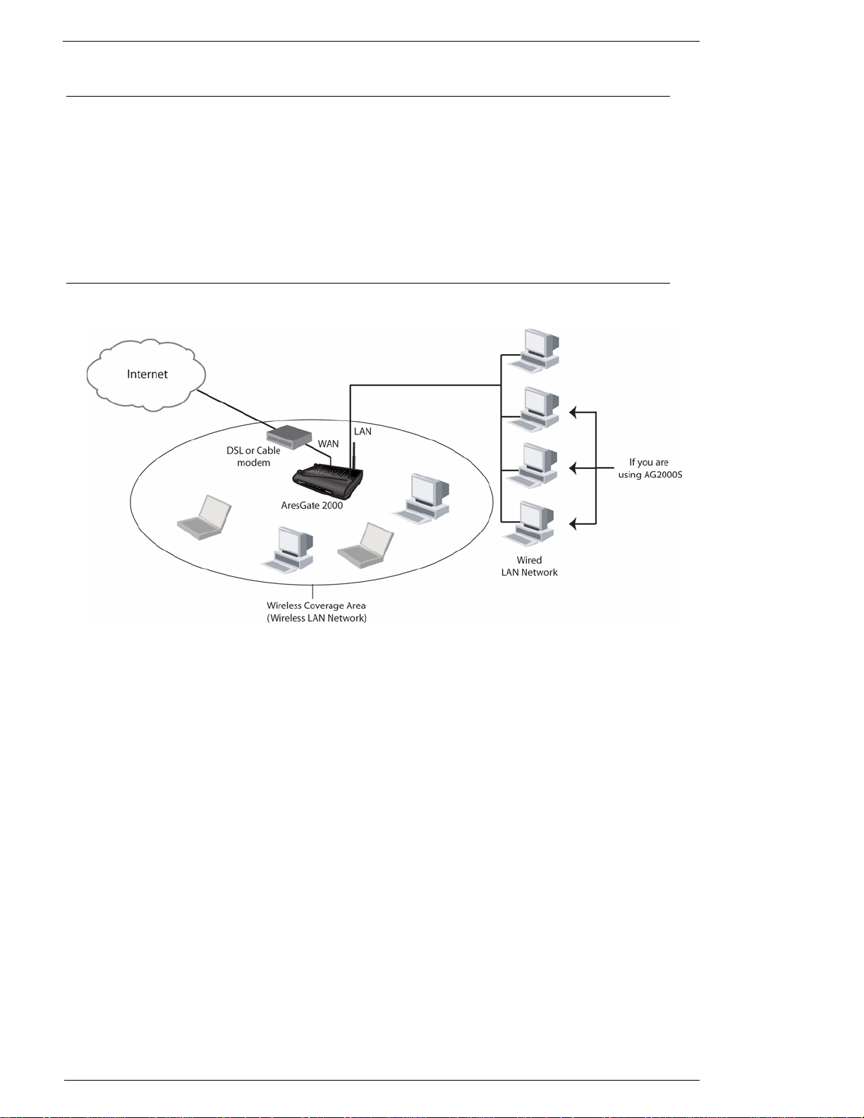
Figure 1.1 Installing a Single AG2000 Network Scenario
The AG2000 provides a connection point to the wireless clients and the wired LAN (See figure above).
It works with your existing Internet access equipment (such as a DSL modem or Cable modem) to provide a gateway to the Internet for your entire network.
Wireless LAN Network
You can easily create a wireless network using your AG2000. The PCs, PDAs or other electronic appliances on your wireless network must have 802.11b-compliant wireless devices already installed in
them. The AG2000 is compatible with any wireless device that is certified by Wi-Fi. To be able to communicate with the AG2000 wireless network successfully, they all need to share the same SSID, channel number and operating mode (infrastructure) as the AG2000. Please refer to Chapter 4 for more
detailed configurations of the AG2000.
Wired LAN Network
The AG2000 can also connect to the wired LAN through the connection from the Ethernet 10/
100BaseT LAN ports on back of the unit. Use a straight-through Ethernet cable to connect the AG2000
to PCs on the LAN network. If you have more than 4 desktop computers in your wired LAN and want
to connect to the AG2000, an extra hub or switch is required to be installed.
2 June, 2002 AG2000Series Software User ’s Guide
Page 7
Network Scenario
1.5.2 Installing Multiple AG2000s
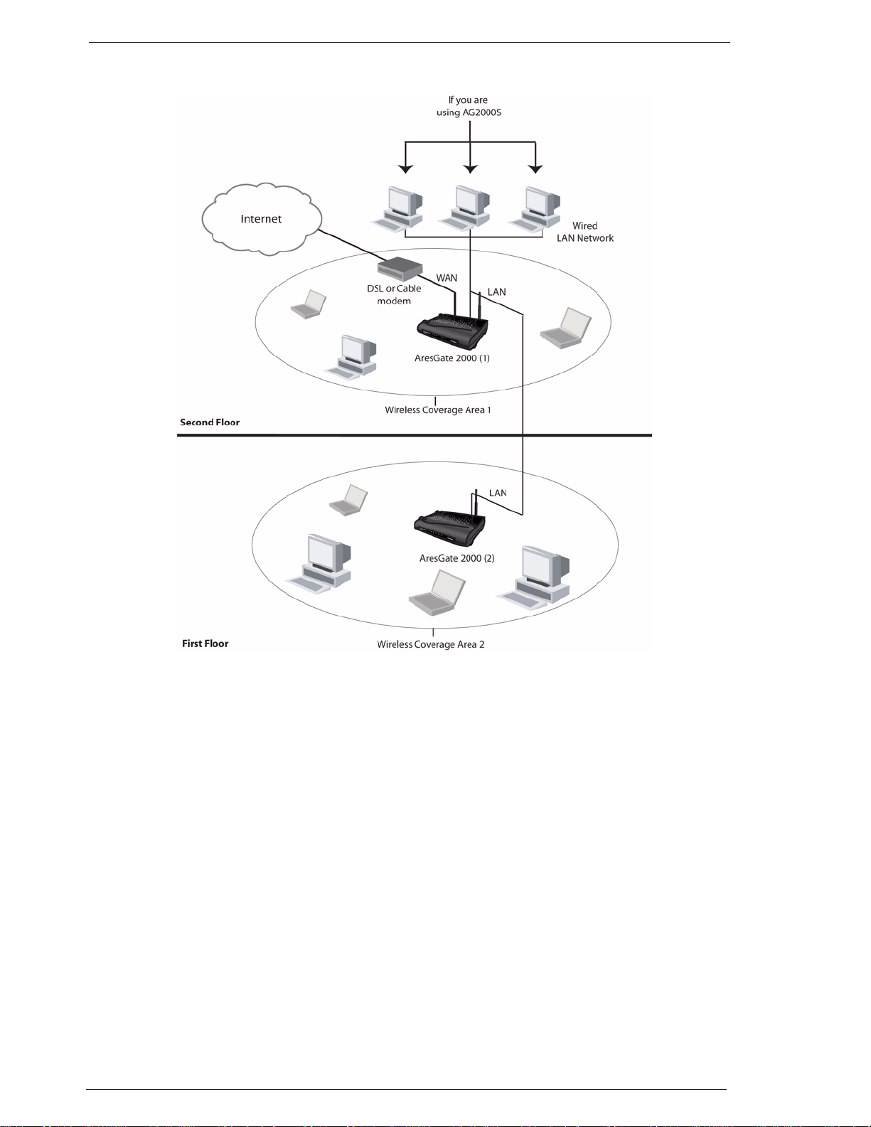
Figure 1.2 Installing Multiple AG2000s Network Scenario
Figure 1.2 displays a typical network scenario that involves multiple AG2000s and PCs. This type of
network scenario provides a solution to larger buildings or homes where a single AG2000 wireless
coverage range is inadequate. The Second Floor AG2000 connects to a DSL or Cable modem and acts
as a router. The First Floor AG2000 connects to the Second Floor AG2000 and acts as a bridge, extending the wireless coverage area.
To complete the setup for Installing Multiple AG2000s, please follow the steps below:
Step 1. Connect the DSL or Cable modem’s Ethernet port to the Second Floor AG2000’s WAN port using a
RJ-45 straight-through Ethernet cable.
Step 2. Connect the Second Floor AG2000’s LAN port to the First Floor AG2000s’ LAN port using a RJ-45
straight-through Ethernet cable.
Step 3. Configure the Second Floor AG2000 by turning the DHCP and NAT features to ON. (DHCP and NAT
is ON by default, please refer to Chapter 4 “Configuration” for details)
Step 4. Configure the First Floor AG2000 by turning the DHCP and NAT features to OFF. (Please refer to the
Chapter 4 Configuration for details)
AG2000Series Software User’s Guide June, 2002 3
Page 8

Network Scenario
Roaming
When a wireless client moves from one coverage area to another, the access point automatically performs client roaming within the same subnet and the service provided to the client is continuous and
seamless. In order to roam in a multiple AG2000s environment, all AG2000s installed need to share the
same SSID, channel number, and WEP keys (if enabled).
4 June, 2002 AG2000Series Software User ’s Guide
Page 9
CHAPTER 2: HARDWARE INSTALLATION
This chapter describes the front and back panel layouts and installation procedure for both
AG2000 and AG2000S.
2.1 Panel Information
2.1.1 AresGate 2000 - Front Panel
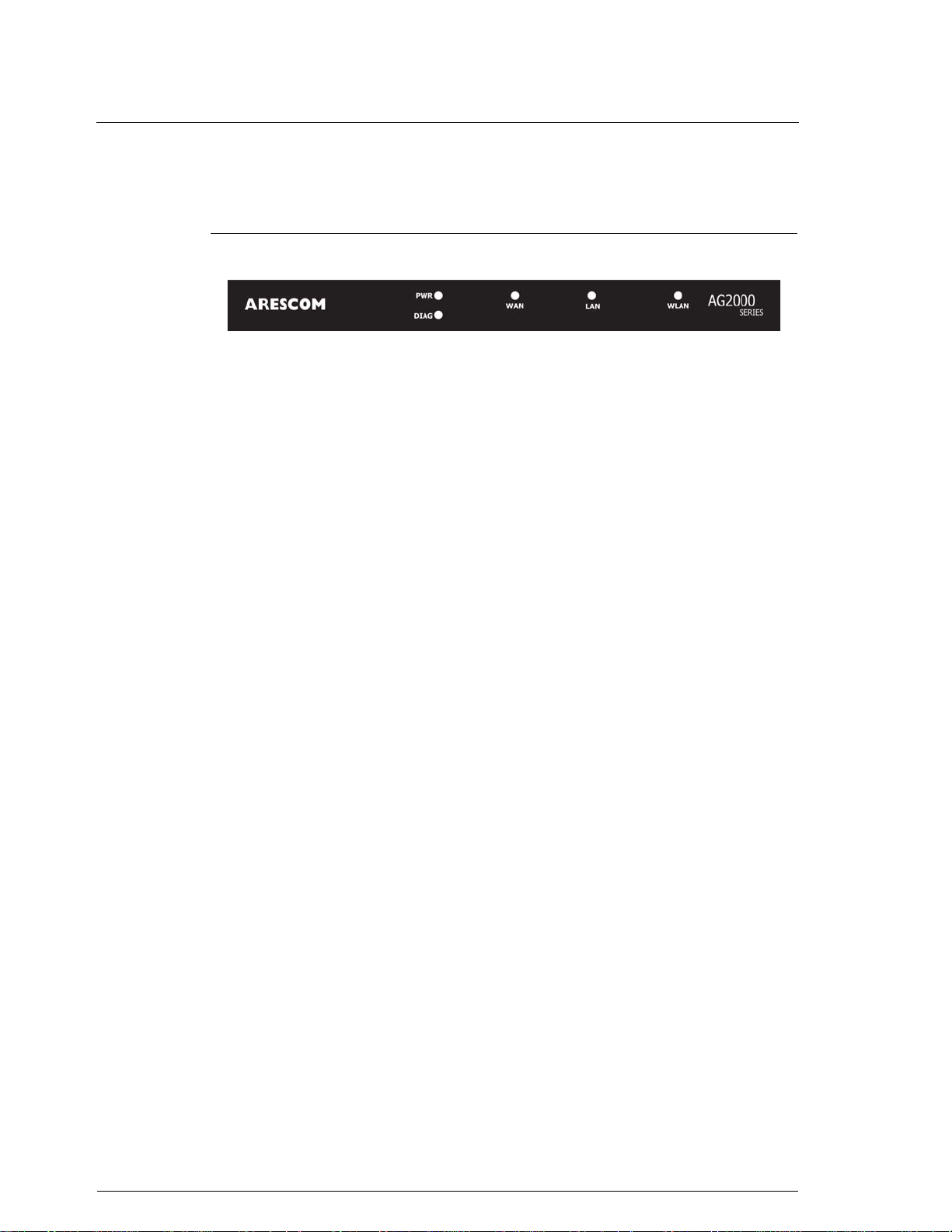
Figure 2.1 AresGate 2000 Front Panel LEDs
PWR (Power)
The PWR LED is ON when power is supplied to the AG2000.
DIAG (Diagnostic)
WA N
LAN
WLAN
The DIAG LED indicates the AG2000 is in a self-diagnostic mode during boot-up.
Once it boots up successfully, the LED will automatically turn off. If there is a software malfunction or a problem with the unit, the LED will remain on.
The WAN LED displays the 10BaseT WAN port Ethernet connection status between
the AG2000 and a broadband device (e.g. Cable modem or DSL modem). The WAN
LED is solid on when a valid Ethernet link is established. The LED flashes when
there is data activity on this port.
The LAN LED displays the 10BaseT Ethernet connection between the AG2000 and
an Ethernet network. The LAN LED is on and remains solid if there is a valid link.
The LED flashes when there is data activity on this port.
The WLAN LED flashes slowly when there is no activity on this wireless interface.
The LED flashes quickly when data is flowing from/to this interface.
AG2000Series Software User’s Guide June, 2002 5
Page 10
2.1.2 AresGate 2000 - Back Panel
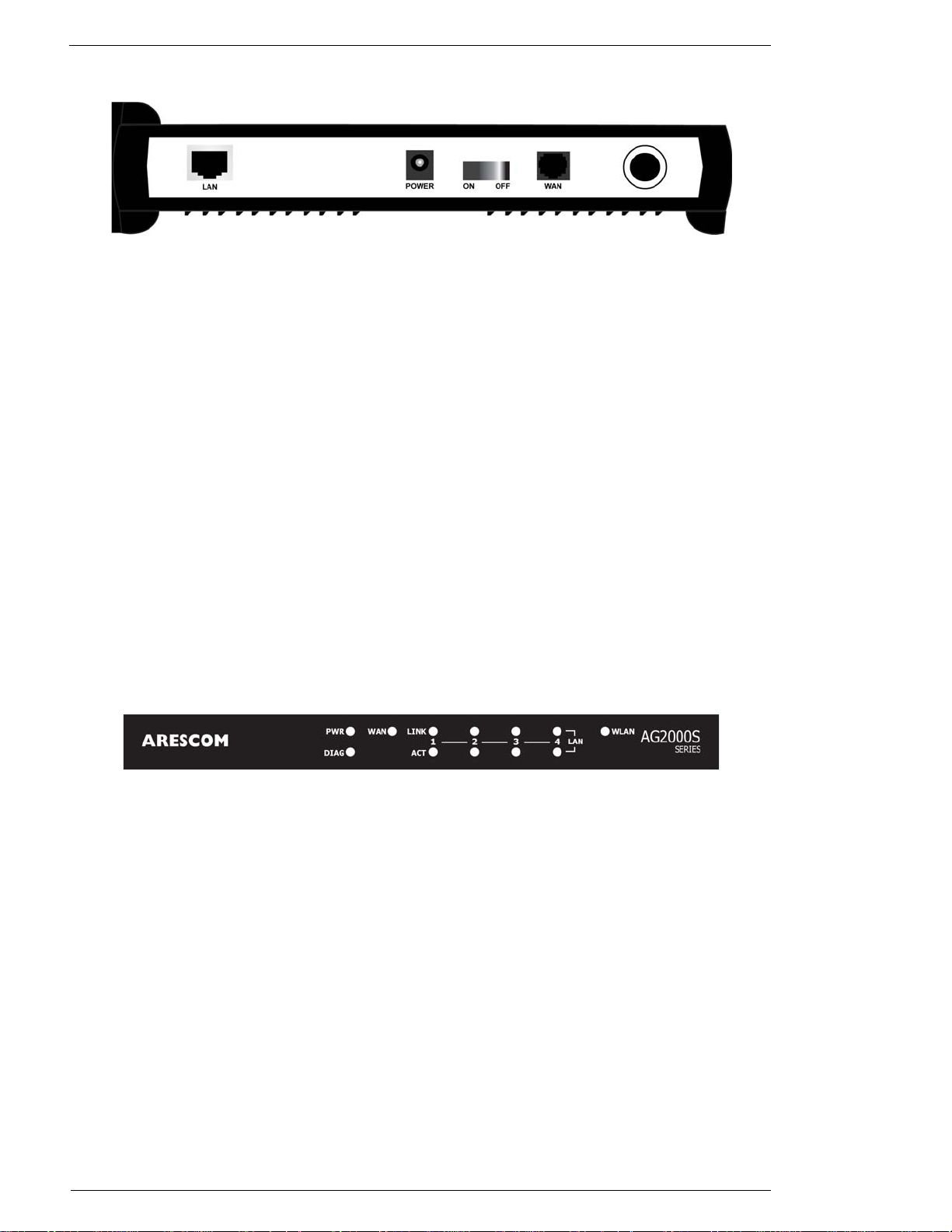
Figure 2.2 AresGate 2000 Back Panel Ports and Switch
LAN
The LAN port connects the AG2000 to a PC, hub or switch on your wired LAN network.
POWER
The POWER port is where you connect the AC power adapter.
ON/OFF Switch
Utilize this ON/OFF switch to turn the AG2000 on or off.
Panel Information
WA N
The 10BaseT WAN port is where you connect your existing Cable/DSL modem.
Antenna Connector
The included external antenna needs to be securely attached to the antenna connector located on the far
right side of the back panel.
2.1.3 AresGate 2000S - Front Panel
Figure 2.3 AresGate 2000S Front Panel LEDs
PWR (Power)
The PWR LED is ON when power is supplied to the AG2000S.
DIAG (Diagnostic)
The DIAG LED indicates the AG2000S is in a self-diagnostic mode during boot-up. Once it boots up
successfully, the LED will automatically turn off. If there is a software malfunction or a problem with
the unit, the LED will remain on.
WA N
The WAN LED displays the 10BaseT WAN port Ethernet connection status between the AG2000S and
a broadband device (e.g. Cable modem or DSL modem). The WAN LED is solid on when a valid
Ethernet link is established. The LED flashes when there is data activity on this port.
6 June, 2002 AG2000Series Software User ’s Guide
Page 11
Location & Placement
LAN
There are 4 sets of LEDs to indicate the Ethernet transmission status of 4 10/100 BaseT LAN ports of
the AG2000S. Each set includes a LINK and an ACT LED.
LINK: The LINK LED is solid when a valid Ethernet link is established.
ACT: The ACT LED flashes when there is data activity on this port.
WLAN
The WLAN LED flashes slowly when there is no activity on this wireless interface. The LED flashes
quickly when data is flowing from/to this interface.
2.1.4 AresGate 2000S - Back Panel
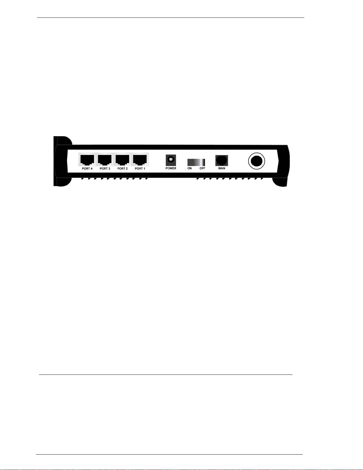
Figure 2.4 AresGate 2000S Back Panel Ports and Switch
LAN (Port 1 - Port 4)
The 4 LAN ports connects the AG2000 to PCs, hubs or switches on your wired LAN network.
POWER
The POWER port is where you connect the AC power adapter.
ON/OFF Switch
Utilize this ON/OFF switch to turn the AG2000 on or off.
WA N
The 10BaseT WAN port is where you connect your existing Cable/DSL modem.
Antenna Connector
The included external antenna needs to be securely attached to the antenna connector located on the far
right side of the back panel.
2.2 Location & Placement
• For maximum wireless coverage, locate an installation spot with a minimum number of walls,
ceilings or other objects that will block the radio transmission between the AG2000 and the
wireless clients.
• Choose an installation location that is away from direct sunlight.
• It is important to place the AG2000 in the center of all the wireless clients.
• Place the AG2000 on the predetermined surface that allows you to see the back panel for convenient cable connection.
AG2000Series Software User’s Guide June, 2002 7
Page 12
Setup Instructions
2.3 Setup Instructions
Before you start the setup process, make sure you follow the instructions below:
Step 1. Disconnect the broadband service. Make sure your Cable or DSL broadband connection is shut down
properly.
Step 2. Turn off the power. Make sure the Cable/ DSL modem and AG2000 equipment are all turned off.
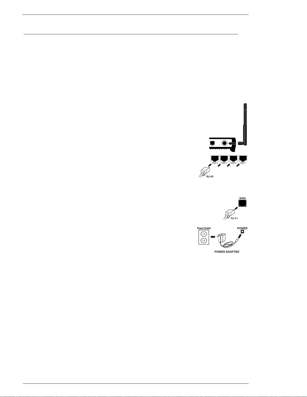
Complete the steps below to connect the cables to the AG2000:
Step 3. Connecting the external antenna.
Tightly attach the external antenna (included) to the antenna connector on the
back panel (For maximum range, make sure the antennas are perpendicular to the
ground).
Step 4. Connecting to the LAN port.
Connect the RJ-45 Ethernet cable (included) from the wired Ethernet LAN
(such as a PC, hub or switch) to the LAN port of the AG2000.
Step 5. Connecting to the WAN port.
Connect the RJ-45 Ethernet cable to the AG2000’s WA N port and the other end of the
same Ethernet cable to the Ethernet port of your existing DSL or Cable modem.
Step 6. Connecting the power.
Connect the AC power adapter to the POWER port of the AG2000. Connect
the AC plug from the power adapter into a wall outlet or power strip.
Step 7. Turning on the power
Power on your DSL/Cable modem first, then power on your AG2000.
8 June, 2002 AG2000Series Software User ’s Guide
Page 13

CHAPTER 3: BEFORE YOU START
AG2000 offers a platform-independent, HTML-based GUI (graphical user interface)
to simplify the setup and configuration of your AG2000 by using web browser. All
the PCs on your LAN network need to be set up properly in order to communicate
with the AG2000. Please carefully read and follow the instructions below before you
start configuring your AG2000:
1. Set up the wireless device:
If you have a wireless device installed on your computer and want to use it to connect
to the AG2000, set its channel number to 6 and SSID to arescom.
NOTE: The SSID is case-sensitive and set the operating mode to Infrastructure.
2. Set up an IP address for your PC:
Since the AG2000 can automatically assign IP address, subnet mask and gateway IP
address to your network PCs through its DHCP server, we highly recommend that
you configure your TCP/IP Properties to “Obtain an IP address automatically”. Select
the proper network adapter, either an Ethernet or a Wireless Adapter, that you are
using to connect to the AG2000.
NOTE: You CANNOT connect a PC to the AG2000 through an Ethernet networking card
and a wireless device installed in your PC at the same time
Follow the instructions below to complete the setup:
For Windows 95/98/ME users:
Step 1. Click Start -> Settings -> Control Panel.
Step 2. Double-click Network.
Step 3. Double-click TCP/IP -> XXXX Ethernet/Wireless Adapters (“XXXX” is the maker
of your Ethernet card).
Step 4. Select the radio button next to Obtain an IP address automatically.
Step 5. Click the Gateway tab and remove all previously installed gateways and click OK.
Step 6. Click OK again.
Step 7. Restart your computer.
For Windows 2000/XP users:
Step 1. Right-click the My Network Places icon in the desktop.
Step 2. Click Properties.
Step 3. Right-click Local Area Connection.
Step 4. Click Properties.
Step 5. Double-click Internet Protocol (TCP/IP).
Step 6. Select the radio button next to Obtain an IP address automatically and click OK.
Step 7. Click OK again.
AG2000Series Software User’s Guide June, 2002 9
Page 14

3. Verify your PC’s IP address:
It MUST be 192.168.10.X (where X is in the range of 2-254). To verify your PC’s IP address, please
follow the instructions below:
For Windows 95/98/ME users:
Step 1. Click Start -> Run.
Step 2. Enter winipcfg and click OK to prompt the IP Configuration window.
Step 3. Select the correct Ethernet or Wireless networking adapter in the white dropdown box.
Step 4. If the IP address displayed in the IP Address box is not 192.168.10.X. (where X is in the range of 2-
254), you need to click Release All -> Renew All buttons to have the correct IP address assigned from
your AG2000 to your PC.
For Windows 2000/XP users:
Step 1. Click Start -> Run.
Step 2. Enter command and click OK to prompt the Windows DOS window.
Step 3. Enter ipconfig and click OK. Windows will display the Windows 2000 IP Configuration information.
Step 4. If the IP address displayed in the IP Address field is not 192.168.10.X. (where X is in the range of 2-
254), you need to enter ipconfig /release and then ipconfig /renew commands to receive a correct IP
address from the AG2000.
4. Verify your PC’s Internet Properties setting if you were previously using an analog
modem.
Please follow the steps below:
Step 1. Click Start, point to Settings, and then click Control Panel.
Step 2. Double-click Internet Options, and then click the Connections tab.
Step 3. Click Never dial a connection, click Apply, and then click OK.
10 June, 2002 AG2000Series Software User’s Guide
Page 15
CHAPTER 4: SOFTWARE CONFIGURATION
4.1 Open Your Browser
Follow the steps below to open your web browser:
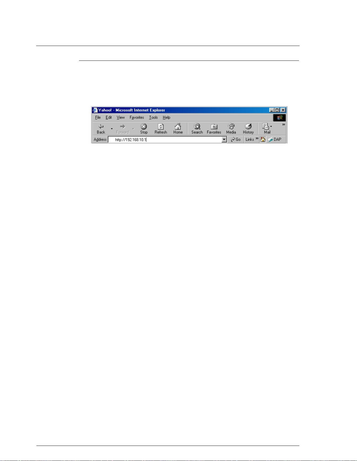
Step 1. Launch a web browser (i.e. Internet Explorer or Netscape Navigator) from your com-
puter.
Step 2. Enter the default URL http://192.168.10.1 and press Enter.
Figure 4.1 Opening an Internet Web Browser
The Web browser may take a minute or two to log on to your AG2000 for first time
access. (Pressing the Enter key or clicking the Go button twice may speed up the log-
on process).
The AG2000’s web GUI is divided into two sections: Basic and Advanced.
The Basic section allows you to configure basic setup features and view the status of
the AG2000. It contains the following GUI pages:
• SETUP
• WIRELESS
• AUTHENTICATION
• DHCP
•USER STATUS
•STATUS
The Advanced section allows users to have greater control over the AG2000. It contains the following pages:
• ADMINISTRATION
•PORT MAPPING
•IP ROUTING
•SNMP
• UPGRADE
AG2000Series Software User’s Guide June, 2002 11
Page 16
4.2 Basic - SETUP
Basic - SETUP
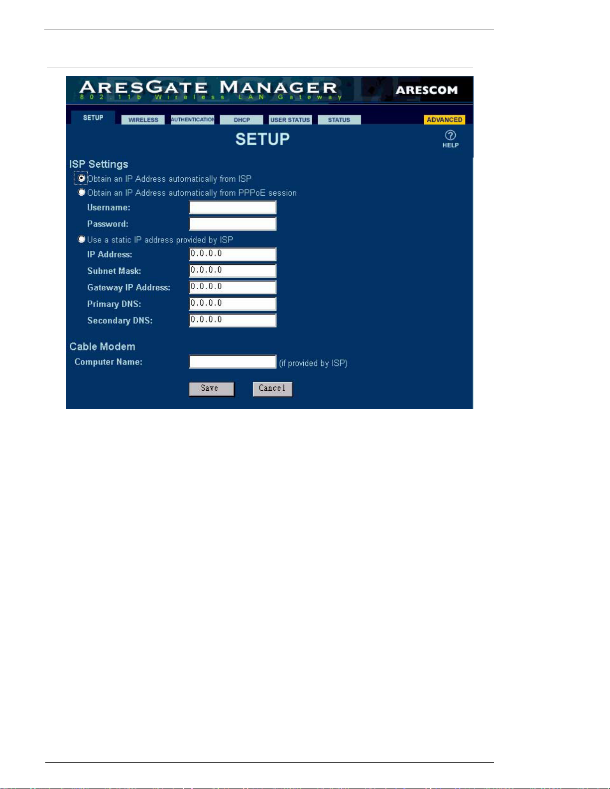
Figure 4.2 SETUP Page
Use the SETUP page to configure the AG2000’s WAN interface, ISP, and Cable modem settings.
4.2.1 ISP Settings
There are three options for you to setup the AG2000’s WAN interface:
If you select the option Obtain an IP Address automatically from your ISP, the AG2000’s DHCP cli-
ent will request a dynamic IP address, subnet mask, and Gateway IP address from your ISP’s DHCP
server. Unless your ISP provides you a static (permanent) IP address, you should select this mode for
the AG2000.
If you select the option Obtain an IP Address automatically from PPPoE session, then you need to
manually enter the required values listed below:
Username: The name of the Internet account provided by your ISP.
Password: The password you use to access your ISP account.
If you select the option Use a static IP address provided by ISP, you need to manually enter the
required values listed below:
IP Address: Enter AG2000’s WAN IP address provided by your ISP.
Subnet Mask: Enter AG2000’s WAN subnet mask provided by your ISP.
Gateway IP Address: Enter AG2000’s Gateway IP Address provided by your ISP.
Primary DNS: Allows you to assign the IP Address of the Primary DNS provided by your ISP.
12 June, 2002 AG2000Series Software User’s Guide
Page 17

Basic - SETUP
Secondary DNS: Allows you to assign the IP Address of the Secondary DNS provided by your
4.2.2 Cable Modem
This section is for cable modem users only. Your ISP may request you to manually enter the Computer
Name (Host Name) for authentication purpose.
Click Save to save the values to your AG2000. If you do not wish to send the configuration to your
AG2000, simply click Cancel.
ISP.
AG2000Series Software User’s Guide June, 2002 13
Page 18
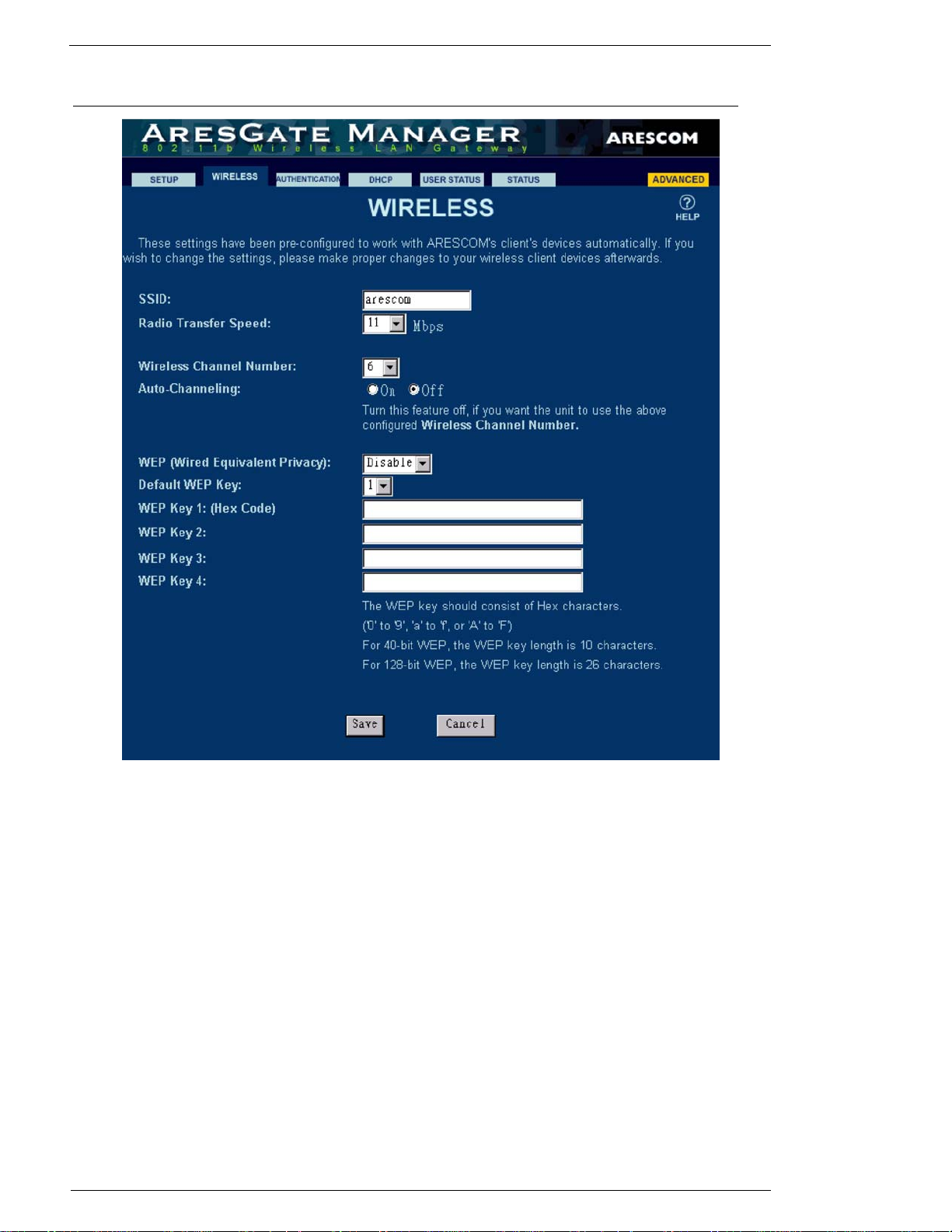
4.3 Basic - WIRELESS
Basic - WIRELESS
Figure 4.3 WIRELESS Page
The WIRELESS page provides the configuration parameters for the AG2000's wireless feature. It contains the following settings:
SSID (Service Set ID)
The SSID is an unique identifier that the AG2000 and wireless clients use to associate with each other.
The SSID can be any alphanumeric entry up to 32 characters long and is case sensitive. The default
SSID is arescom.
Radio Transfer Speed
The radio transfer speed is the data rate that the AG2000 uses to connect to a wireless client. You can
choose the wireless data transfer rate of the AG2000 ranging from 1, 2, 5.5 to 11Mbps. The AG2000
will always attempt the speed you have selected to link to the wireless clients. If the link cannot be
established because of interference or other obstacles, the AG2000 automatically gears down the speed
to the next lowest rate until a link is successfully established. The default radio transfer speed is
11Mbps.
14 June, 2002 AG2000Series Software User’s Guide
Page 19

Basic - WIRELESS
Wireless Channel Number
A wireless channel is a specific frequency band at which the AG2000 communicates with a client. You
can select one of the 11 channels from the dropdown menu for the AG2000 to use. However, if you
enable the Auto-Channeling feature below, the channel you selected here will be ignored by the system. Instead, it will be replaced by the channel number that the system selected. The default channel
number is 6.
Auto-Channeling
When you turn on the auto-channeling feature, the AG2000 automatically scans the surrounding radio
signals, selects the least interference and lowest traffic channel to use, and displays this selected channel in the above Wireless Channel Number. The default setting of this feature is Off.
NOTE: Turning on the Auto-Channeling feature may cut off the wireless connection between the AG2000 and
your PC. Click Re-Scan in the Wireless Configuration Utility program installed in your PC to re-estab-
lish the wireless connection.
WEP (Wired Equivalent Privacy)
The Wired Equivalent Privacy (WEP) is used to protect wireless communication from eavesdropping.
Since WEP uses a secret key shared between communicators, if you enable the WEP feature, entering
the WEP key values below is required.
Default WEP Key
The AG2000 supports 40-bit and 128-bit WEP keys. For 40-bit WEP encryption, you need to enter 10
hexadecimal digits in one of the key fields below. For 128-bit WEP encryption, you need to enter 26
hexadecimal digits in one of the key fields below. Although there are four key fields you can set up for
the AG2000, you can choose only one at a time from the Default WEP Key dropdown menu. The WEP
key is not case-sensitive. The default key field is 1.
1. Enter either 40-bit WEP keys as 10 HEX digits or 128-bit WEP keys as 26 Hex digits
here.
2. Enter either 40-bit WEP keys as 10 HEX digits or 128-bit WEP keys as 26 Hex digits
here.
3. Enter either 40-bit WEP keys as 10 HEX digits or 128-bit WEP keys as 26 Hex digits
here.
4. Enter either 40-bit WEP keys as 10 HEX digits or 128-bit WEP keys as 26 Hex digits
here.
Click Save to save the values to your AG2000. If you do not wish to send the configuration to your
AG2000, simply click Cancel.
AG2000Series Software User’s Guide June, 2002 15
Page 20
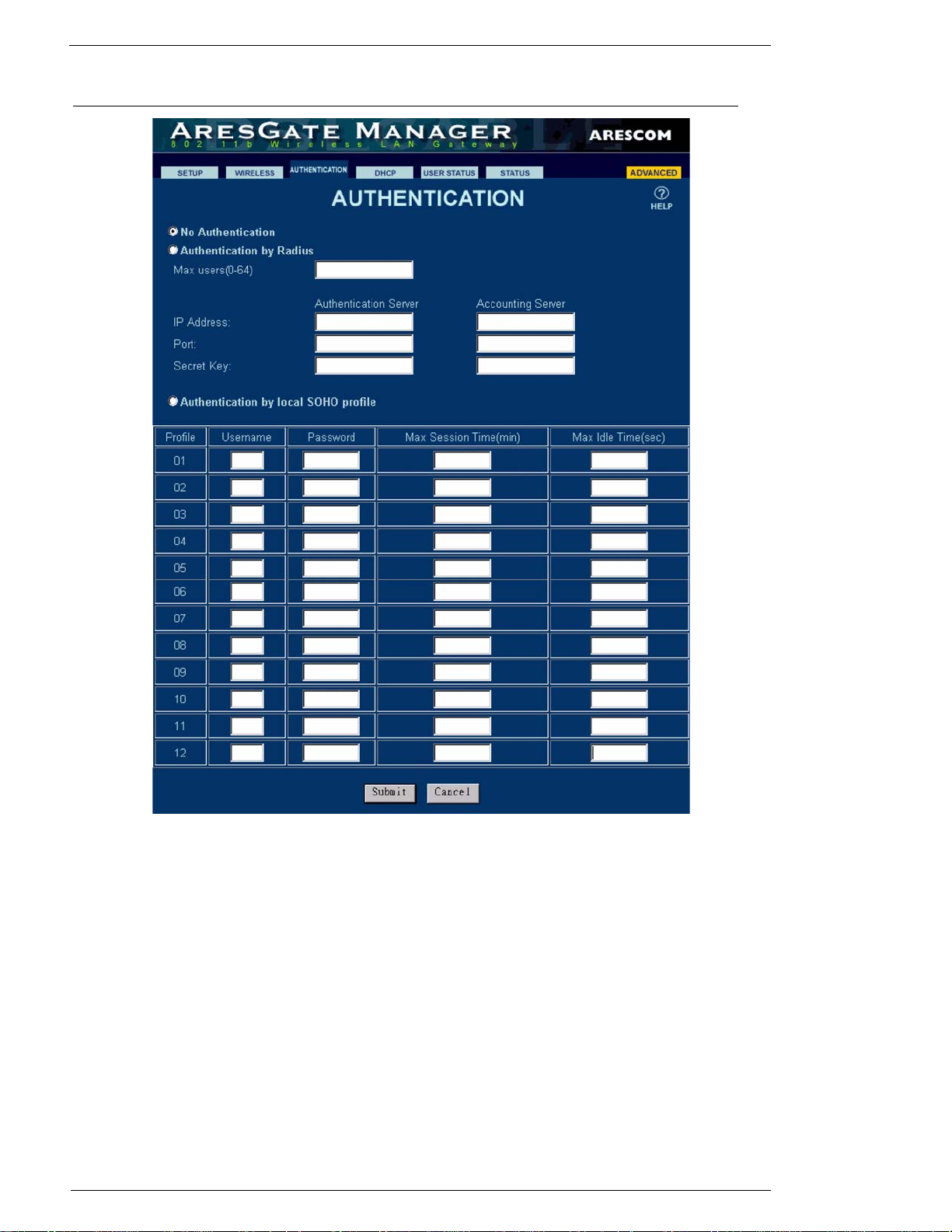
4.4 Basic - AUTHENTICATION
Basic - AUTHENTICATION
Figure 4.4 AUTHENTICATION Page
The AUTHENTICATION page allows you to configure the AP to establish communication with a
RADIUS server for the purpose of user authentication and accounting. If the user passes the authentication, then the user is allowed access to the network and service that the AP provides. The AP performs
both MAC address and EAP (Extensible Authentication Protocol) authentication automatically for all
the associated wireless clients. MAC address authentication is based on the user's MAC address of his/
her wireless device for authenticating while EAP authentication is based on the username and password. There are three options for you to choose:
If you select No Authentication, then the AG2000 will not perform the authentication process.
If you select Authentication by Radius, then the AG2000 will perform the authentication process
through an external RADIUS (Remote Authentication Dial-In User Service) server. Please follow the
steps below to set up the RADIUS server:
Step 1. Enter the maximum number of users allowed to access the AG2000 in the Max users (0-64) field.
16 June, 2002 AG2000Series Software User’s Guide
Page 21

Basic - AUTHENTICATION
Step 2. Enter the IP address of the authentication server in the IP Address field of the Authentication Server
section.
Step 3. Enter the port number of the authentication server in the Port field. The default port number is 1812.
Step 4. Enter the shared secret key used by the authentication server in the Secret Key field.
Step 5. Repeat Steps 1 - 4 for the Accounting Server section. The default port number of the accounting
server is 1645.
If you select Authentication by local SOHO profile, then you need to manually enter values in the
table below. Please follow the steps below to set up authentication by local SOHO profile:
Step 1. Select a profile.
Step 2. Enter a username in the Username field.
Step 3. Enter a password in the Password field.
Step 4. Specify the maximum amount of time (in minutes) a user is allowed to access the Internet via AG2000
in the Max Session Time (min) field.
Step 5. Specify the maximum amount of time (in seconds) a user can stay idly online before he/she is discon-
nected from the Internet in the Max Idle Time (sec) field.
When you are ready, click Submit to save the values to your AG2000. If you do not wish to send the
configuration to your AG2000, simply click Cancel.
AG2000Series Software User’s Guide June, 2002 17
Page 22
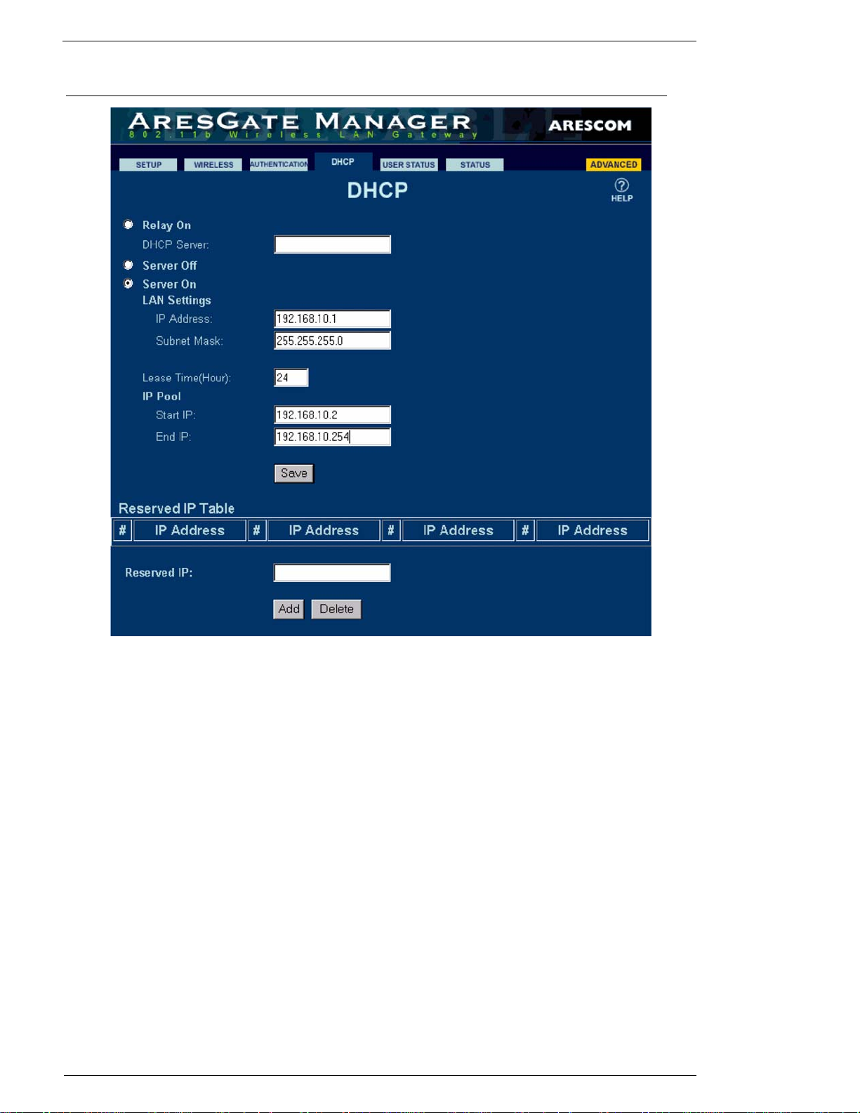
4.5 Basic - DHCP
Basic - DHCP
Figure 4.5 DHCP Page
The DHCP page allows you configure the DHCP feature and assign or reserve IP addresses. At default,
the DHCP feature is set to Off. There are three options for you to choose:
If you select Relay On, then you have activated AG2000’s DHCP relay feature. It is necessary for you
to configure a DHCP server’s IP address in the DHCP Server field to allow DHCP packets to forward
properly.
If you select Server Off, then you have de-activated AG2000’s DHCP server feature.
If you select Server On, then you have activated AG2000’s DHCP server feature for automatic assignment of IP addresses, subnet mask, gateway IP address, and DNS to the DHCP clients. Please follow
the steps below for a complete DHCP setup:
Step 1. Enter the LAN IP address of the AG2000 in the IP Address field under LAN Settings. The default
LAN IP address is 192.168.10.1.
Step 2. Enter the subnet mask of the AG2000 in the Subnet Mask field under LAN Settings. The default LAN
subnet mask is 255.255.255.0.
Step 3. Enter the amount of time that a network device can have (lease) a private IP address before AG2000
makes the IP address available for re-assignment in the Lease Time (Hour) field.
18 June, 2002 AG2000Series Software User’s Guide
Page 23

Basic - DHCP
Step 4. If you wish to specify a pool of IP addresses that can be dynamically assigned as private IP addresses,
you can enter an IP address in the Start IP field as the beginning and another IP address in the End IP
field as the end of the IP range.
NOTE: The IP Pool feature for the DHCP server is based on the LAN IP address settings. Therefore, you must
first configure a LAN IP address and subnet mask in the above LAN Setting section before using
DHCP.
Step 5. When you are finished with the DHCP configuration, click Save.
4.5.1 Reserved IP Table
The Reserved IP Table displays all the private IP addresses that are reserved by the user for other
usages. To reserve a new private IP address, simply enter the IP address in the Reserved IP field and
click Add. To remove an IP address from the Reserved IP Table, enter the IP address and click Delete.
AG2000Series Software User’s Guide June, 2002 19
Page 24
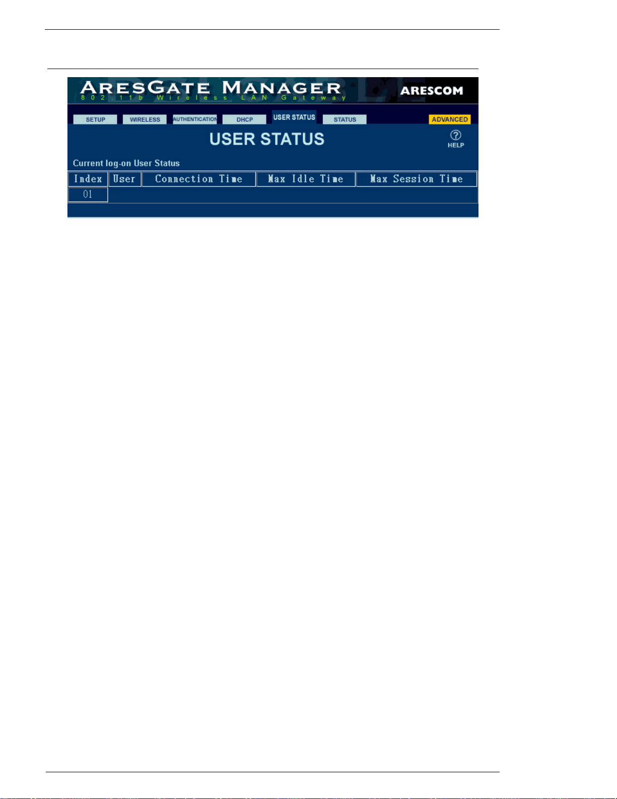
4.6 Basic - USER STATUS
Figure 4.6 USER STATUS Page
4.6.1 Current Log-on User Status
The USER STATUS page displays the current logon user status. It contains the following information:
Index: A serial ID number, which is assigned by the system, for logon users.
User: It displays user’s identification as MAC address for MAC authenticated user or
username for EAP authenticated user.
Connection Time: It indicates the connection time of the service from the beginning of the
session.
Max Idle Time: When the idle data traffic time exceeds the maximum idle time configured by a
central RADIUS server, the AG2000 stops the service and ends session.
Max Session Time: It shows the time that the user is allowed to use the service.
Basic - USER STATUS
20 June, 2002 AG2000Series Software User’s Guide
Page 25
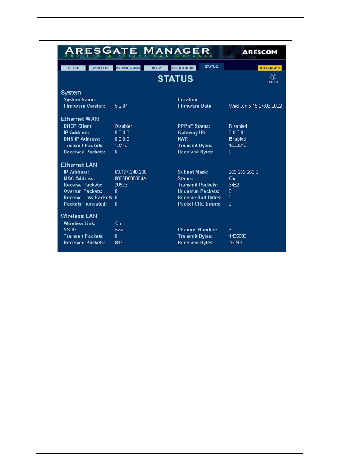
Basic - STATUS
4.7 Basic - STATUS
Figure 4.7 STATUS Page
The STATUS page displays AG2000’s network statistics and general system information.
System
System Name: The device name of the AG2000 used for identification purpose.
Location: The location name where the AG2000 is installed.
Firmware Version: Version of the firmware installed currently.
Firmware Date: The firmware release date.
Ethernet WAN
DHCP Client: The DHCP client status on the WAN interface.
PPPoE Status: The current PPPoE connection status.
IP Address: The WAN IP address of AG2000.
Gateway IP: The gateway IP address of AG2000.
DNS IP Address: The DNS IP address of AG2000.
NAT: The NAT function status of AG2000.
Transmit Packets: The total number of packets transmitted on the WAN port.
Transmit Bytes: The total number of bytes transmitted on the WAN port.
Received Packets: The total number of packets received on the WAN port.
AG2000Series Software User’s Guide June, 2002 21
Page 26

Received Bytes: The total number of bytes received on the WAN port.
Ethernet LAN
IP Address: The IP address of AG2000’s LAN port.
Subnet Mask: The subnet mask of AG2000's LAN port.
MAC Address: The MAC address of AG2000's LAN port.
Status: The current LAN connection status.
Received Packets: The total number of packets received on the Ethernet port.
Transmit Packets: The total number of packets transmitted on the Ethernet port.
Overrun Packets: The total number of receiver overruns.
Underrun Packets: The total number of transmitter underruns.
Receive Loss Packets: The total number of packets lost.
Receive Bad Bytes: The total number of bad bytes received.
Packets Truncated: The total number of truncated packets received.
Packet CRC Errors: The total number of packets received with an incorrect CRC.
Wireless LAN
Basic - STATUS
Wireless L i nk: Indicates whether or not there is a valid wireless connection between AG2000
and other PCs.
SSID: Displays the SSID of the AG2000.
Channel Number: Displays AG2000’s current wireless channel number.
Transmit Packets: The total number of packets transmitted on the wireless interface.
Transmit Bytes: The total number of bytes transmitted on the wireless interface.
Received Packets: The total number of packets received on the wireless interface.
Received Bytes: The total number of bytes received on the wireless interface.
22 June, 2002 AG2000Series Software User’s Guide
Page 27
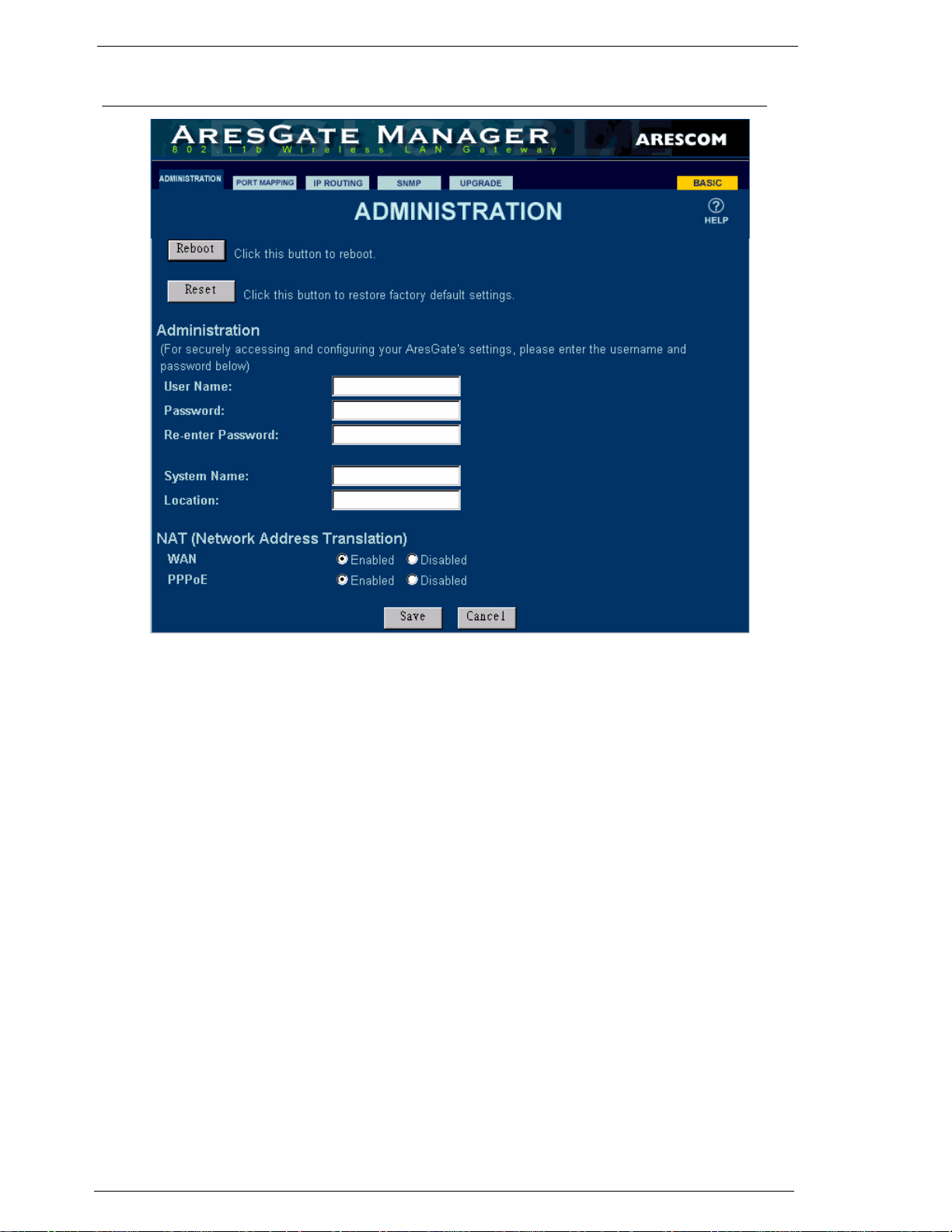
Advanced - ADMINISTRATION
4.8 Advanced - ADMINISTRATION
Figure 4.8 ADMINISTRATION Page
To ensure AG2000’s maximum administrative security, the Administration page in the advanced section allows you to enter a desired username and password. In addition, you can choose to enable or disable AG2000’s NAT feature here on this page.
Reboot: Click this button to reboot AG2000 remotely. It acts the same as the power
Reset: Click this button to restore AG2000 to manufacturer default conditions.
4.8.1 Administration
User Name: Enter a desired username to set up administrator authorization for the
Password: By entering a desired password, it provides maximum security for your
Re-enter Password: Enter your password again to make sure that you have typed in the correct
System Name: Enter a desired device name for the AG2000 for identification purpose.
Location: Enter the location name where the AG2000 is installed.
switch on the back of the unit.
management system. It can be any alphanumeric code up to 32 characters
long. The default username is admin.
AG2000 by limiting access only to users with the correct password. The
password can be any alphanumeric code up to 32 characters long. The default
password is admin.
When you type in your password, it will appear as asterisk (****).
password.
AG2000Series Software User’s Guide June, 2002 23
Page 28

4.8.2 NAT (Network Address Translation)
NAT allows the AG2000 to perform IP-sharing, which enables multiple PCs on your LAN with Private
IP addresses to share Internet access by using only one Public IP address. USE NAT page to enable or
disable this feature on WAN or PPPoE interface.
WAN: You can choose to Enable or Disable the NAT feature on the WAN interface.
PPPoE: You can choose to Enable or Disable the NAT feature on the PPPoE interface.
When you are ready, click Save to save the values to your AG2000. If you do not wish to send the configuration to your AG2000, simply click Cancel.
Advanced - ADMINISTRATION
24 June, 2002 AG2000Series Software User’s Guide
Page 29
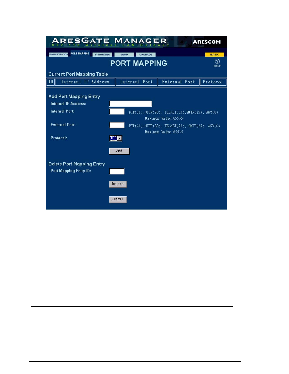
Advanced - PORT MAPPING
4.9 Advanced - PORT MAPPING
Figure 4.9 PORT MAPPING Page
The Port Mapping page provides specific application support or services, such as web hosting, FTP
server, mail server or other applications.
4.9.1 Current Port Mapping Table
The Current Port Mapping Table displays the ID (index number), Internal IP Address, Internal Port
#, External Port #, and Protocol type for each entry.
4.9.2 Add Port Mapping Entry
Internal IP Address: Enter the IP Address of the network PC that provides the service(s). The IP
address must be within the AG2000’s 192.168.10.1 private subnet. Since
AG2000’s DHCP feature is set to ON at default, it is recommended to assign a
static IP address to the PC.
NOTE: Each time you assign a static IP address (in the range of 192.168.10.2 - 192.168.10.254) to your net-
work PC, reboot your AG2000 so the DHCP server can reserve it.
Internal Port: A port is used to distinguish requests for different services. For example, port
#21 is for FTP, #80 is for HTTP, #23 is for Telnet, while #25 is for SMTP, etc.
External Port: The external port is associated with the Dial-Out IP Address.
AG2000Series Software User’s Guide June, 2002 25
Page 30

Advanced - PORT MAPPING
Protocol: The protocol that is used on the service or application. You can choose TCP or
UDP protocols.
4.9.3 Delete Port Mapping Entry
To delete an entry from the port mapping table above, enter the associated ID number and click Delete.
Click Cancel to ignore the settings.
Below is an example on how to set up a WEB hosting service:
Step 1. Enter 192.168.10.100 in the Internal IP Address field (Assuming the WEB server’s IP address is
192.168.10.100 and subnet mask is 255.255.255.0).
Step 2. Enter 80 in the Internal Port field.
Step 3. Enter 80 in the External Port field.
Step 4. Select TCP from the Protocol dropdown menu.
Step 5. Click Add to add the entry in the AG2000’s Port Mapping Table.
26 June, 2002 AG2000Series Software User’s Guide
Page 31
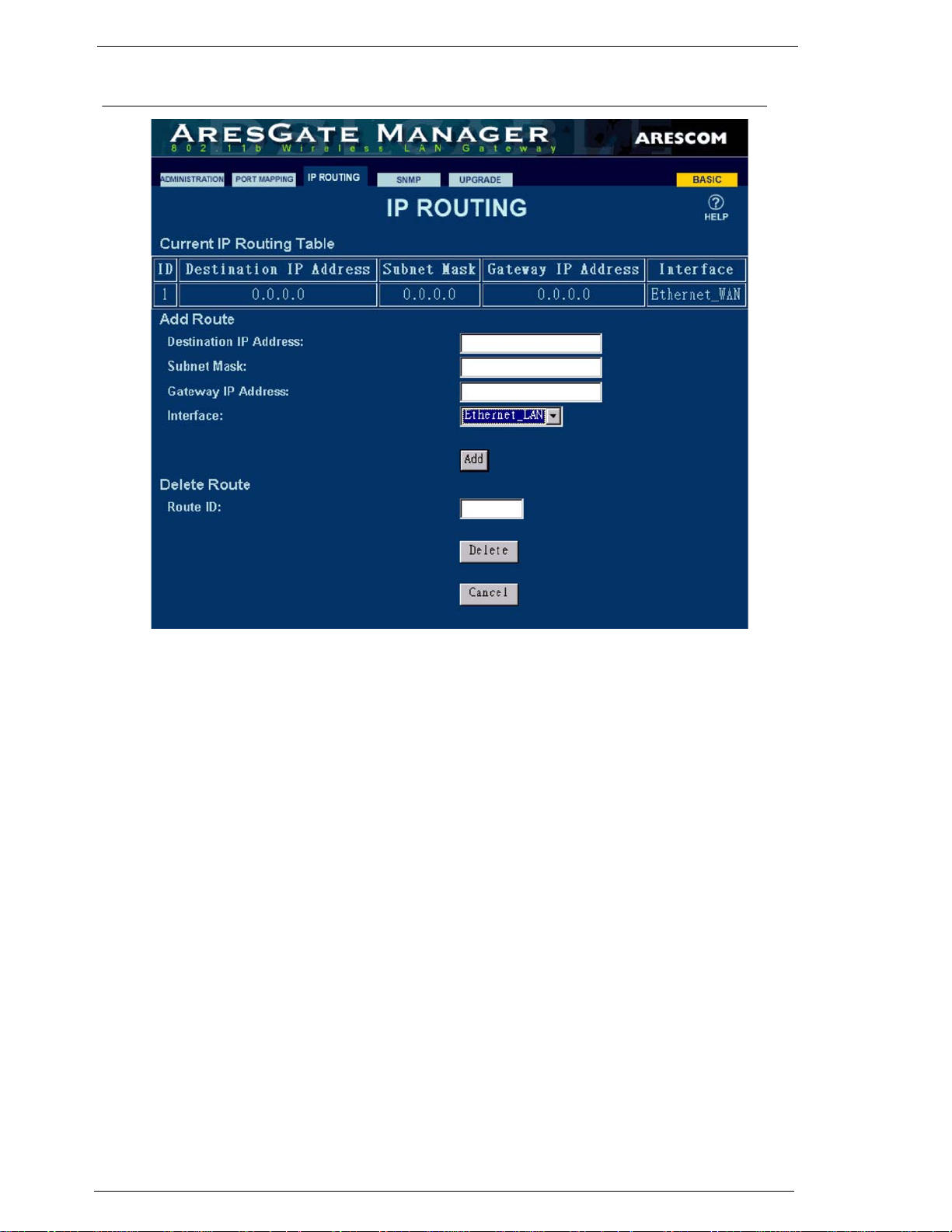
Advanced - IP ROUTING
4.10 Advanced - IP ROUTING
Figure 4.10 IP ROUTING Page
Use the IP ROUTING page to create paths or routes for the AG2000 to forward data packets to their
destinations. You need to create an IP route when there are other routers on your LAN.
4.10.1Current IP Routing Table
The Current IP Routing Table displays the index number (ID), Destination IP Address, Subnet Mask,
Gateway IP Address, and Interface for each entry.
4.10.2Add Route
Destination IP Address: The IP address of where data packets are to be sent.
Subnet Mask: The subnet mask of the above Destination IP Address.
Gateway IP Address: The IP address of the router on the LAN where data packets are to be sent. The
Gateway IP Address can only be set if the route uses the LAN interface.
Interface: Determines data packets are to be sent through the LAN or WAN interface.
4.10.3Delete Route
Route ID: To delete a route from the routing table, enter the associated ID number and
click the Delete button. Click Cancel to ignore the settings.
AG2000Series Software User’s Guide June, 2002 27
Page 32
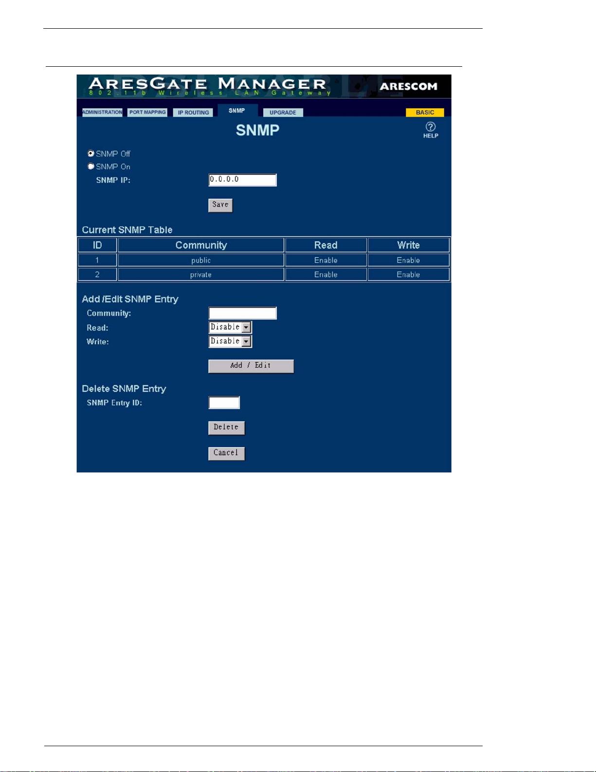
4.11 Advanced - SNMP
Advanced - SNMP
Figure 4.11 SNMP Page
Use the SNMP (Simple Network Management Protocol) page to add or delete SNMP entries. This
page also lists all the SNMP entries in the AG2000 device.
4.11.1 Current SNMP Table
The Current SNMP Table provides the most up-to-date SNMP entry information including the entry’s
ID number, community string and access rights. There are two default entries: public and private.
4.11.2 Add SNMP Entry
Community: Allows you to enter the SNMP string.
Read: Allows you to enable or disable the Read function on this community.
Write: Allows you to enable or disable the Wri te function on this community.
Click Add/Edit to add this entry in the SNMP table.
28 June, 2002 AG2000Series Software User’s Guide
Page 33

Advanced - SNMP
4.11.3 Delete SNMP Entry
SNMP Entry ID: Enter the associated ID number that you want to remove from the table. The
last SNMP entry cannot be deleted.
Click Delete to remove this entry from the SNMP table.
AG2000Series Software User’s Guide June, 2002 29
Page 34
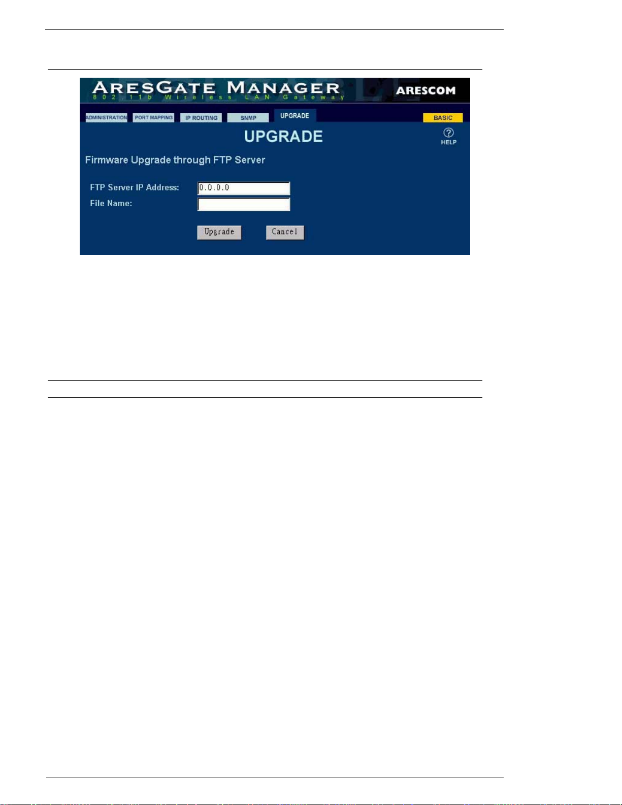
4.12 Advanced - UPGRADE
Figure 4.12 UPGRADE Page
Use the UPGRADE page to update the AG2000's firmware through FTP (File Transfer Protocol) from
a FTP server. You can perform the firmware upgrade by following the steps below:
Advanced - UPGRADE
Step 1. In the FTP Server IP Address field, enter the IP address of the FTP server where the new firmware file
is located. The FTP server should allow anonymous login.
Step 2. In the File Name field, enter the file name of the new firmware that you want to load and install.
NOTE: The firmware image file must be located in the root directory of the FTP file server.
Step 3. Click Upgrade to begin the firmware upgrade process. When the upgrade is complete, the AG2000 will
reboot automatically. Click Cancel if you do not wish to upgrade the unit.
30 June, 2002 AG2000Series Software User’s Guide
Page 35

CHAPTER 5: TROUBLESHOOTING
5.1 FAQ
Symptoms Possible Cause Resolution
Make sure the SSID, channel # and
operating mode settings are all the
same as the AG2000.
Make sure the PC is within the wireless coverage area.
Make sure your PC’s IP address is in
the subnet of 192.168.10.1..
Reconnect the Ethernet cable into the
10/100 Ethernet/LAN port.
Replace the Ethernet cable.
A straight-through Ethernet cable is
required to connect the LAN port of
the AG2000 to a PC’s NIC card.
For the correct pinouts of crossover
or straight-through Ethernet cable,
please refer to Appendix C.
Reconnect the Ethernet cable into the
WAN port of the AG2000.
Replace the Ethernet cable.
A straight-through Ethernet cable is
required to connect the WAN port of
the AG2000 to the Ethernet port of
your DSL/Cable modem.
For the correct pinouts of crossover
or straight-through Ethernet cable,
please refer to Appendix C.
Change your PC’s Ethernet IP
address to 192.168.10.1 subnet. Setting up “Obtain an IP address automatically” in the NIC’s TCP/IP is
recommended.
Reconnect the Ethernet cable into the
Ethernet port.
Cannot access the
AG2000 from a
wireless device.
Ethernet LAN
LED not turned
on after Ethernet
cable is connected.
Ethernet WAN
LED not turned
on after Ethernet
cable is connected.
Cannot access the
AG2000 from a
Ethernet networking card.
Incorrect settings on
the wireless device.
Out of the wireless
coverage range.
Incorrect IP address in
your PC.
Ethernet cable loose or
not connected properly.
Ethernet cable defective.
Incorrect cable.
Ethernet cable loose or
not connected properly.
Ethernet cable defective.
Incorrect cable.
Your PC Ethernet
NIC’s IP address and
the AG2000’s LAN IP
address are not in the
same subnet.
Ethernet cable loose or
not connected properly.
AG2000Series Software User’s Guide June, 2002 31
Page 36
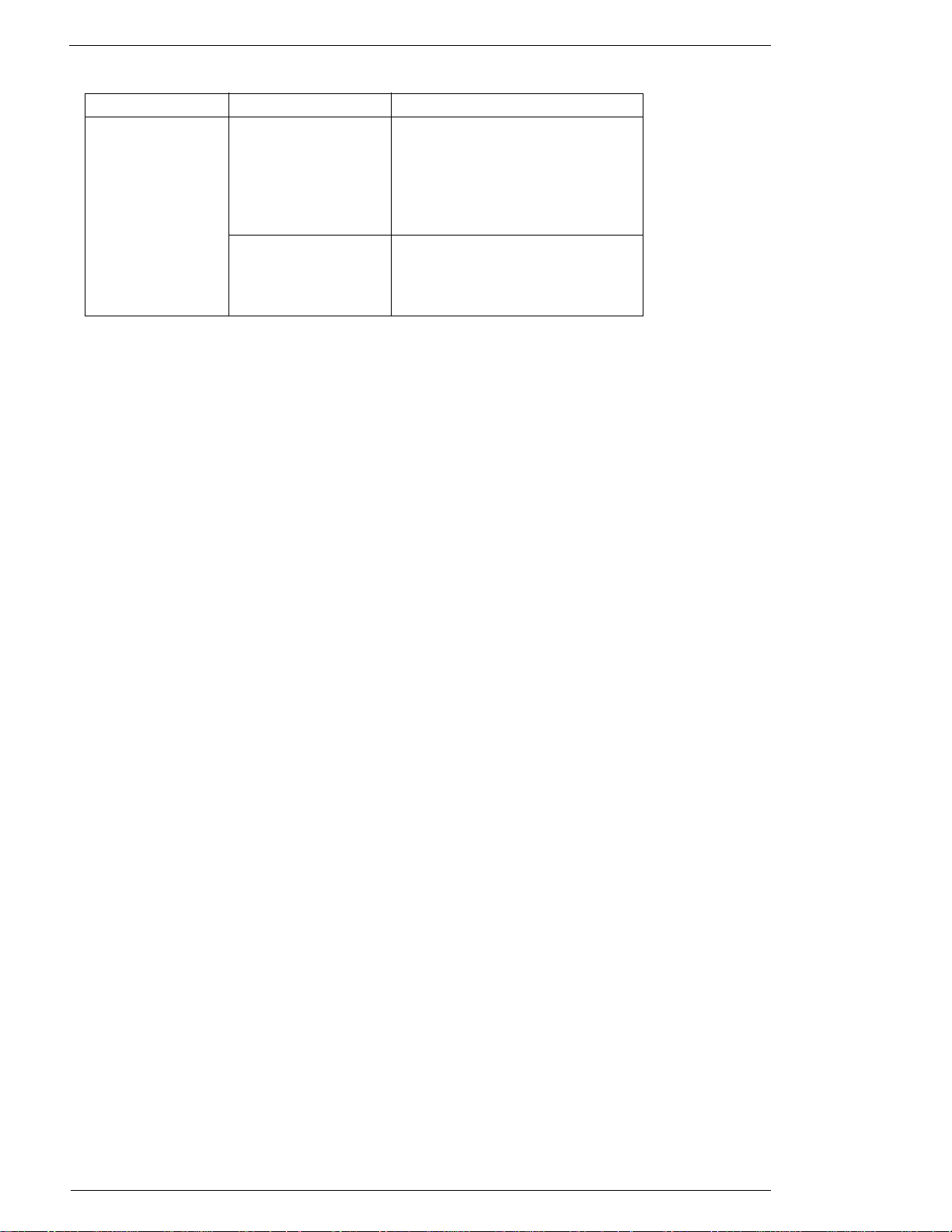
Symptoms Possible Cause Resolution
Check the A21000’s WAN IP address
in the STATUS page of the Web GUI.
Make sure the WAN IP address, subnet mask, Gateway IP address and
DNS all exist. If not, reboot your
cable/DSL modem and the AG2000.
Call your ISP to find out if your ISP
is using PPPoE or other protocols.
Please refer to the Chapter 4 for more
Can access the
AG2000 web GUI,
but still cannot get
Internet access.
No WAN IP address in
the AG2000.
Incorrect setup in the
AG2000.
details in configuring the AG2000.
FAQ
32 June, 2002 AG2000Series Software User’s Guide
Page 37

APPENDIX A: TECHNICAL SPECIFICATIONS
A.1 Hardware Specifications
WAN Interface
• One Ethernet 10BaseT (IEEE 802.3) port (RJ-45).
LAN Interface
• AG2000: One 10BaseT (IEEE 802.3) Ethernet port (RJ-45).
• AG2000S: Four 10/100 BaseT Ethernet switching ports (RJ-45).
Wireless LAN Interface
• IEEE 802.11b High Rate compliant.
• Operating in the unlicensed 2.4GHz ISM band.
• Operation Frequency/Channels (Either one below):
- North America/FCC: 2.412~2.462 GHz (11 channels).
- Europe/ETS: 2.412~2.472 GHz (13 channels).
- Japan TELEC: 2.412~2.472 GHz (14 channels).
• Modulation Technique: Direct Sequence Spread Spectrum (CCK, DQPSK,
DBPSK).
Antenna
LEDs
• Dynamic Rate Shifting: 11, 5.5, 2 and 1Mbps.
• Media Access Protocol: CSMA/CA with ACK.
• Security Management: 40-bit, 128-bit WEP (wired equivalent privacy)
Encryption.
• Maximum Output Power: 17dBm (50mW).
• Removable 3-dBi diversity high gain dipole antenna.
AG2000
•PWR
•DIAG
•WAN
•LAN
•WLAN
AG2000s
•PWR
•DIAG
•WAN
AG2000Series Software User’s Guide June, 2002 33
Page 38

•LAN/LINK 1 - 4
•LAN/ACT 1 - 4
•WLAN
Mechanical
• Dimensions: 8” (w) x 5.75” (d) x 1.5” (h).
• Weight: 1.5 lbs.
Operating Environment
• Operating temperature: 0°C to 40°C (32°F to 104°F).
• Operating humidity: 0% to 95% non-condensing.
Power
External AC Power Adapter
• Input: 230V 85mA or 120V 155mA, 47-60 Hz.
• Output: 13.5V AC, 1A.
• Power consumption: 8.5 watts nominal.
Power On/Off Switch
Compliance / Regulatory
• EMI: FCC Part15 Class B & Part 15C, CE EN55022 Class B.
• Telecom: FCC Part 68.
• Wi-Fi Certified.
• Immunity: CE EN55024.
• Safety: CE EN60950
34 June, 2002 AG2000Series Software User’s Guide
Page 39

A.2 Software Features
Authentication
802.1x Authentication
• EAP/ MD5 (PPP Extensible Authentication Protocol, RFC 2284) mechanism for authentication.
• RADIUS server (RFC2865, RFC 2869)
• RADIUS Accounting (RFC 2866)
MAC Authentication
• Authentication through the client's MAC address (RFC 2865)
Web Re-direction
• Unauthorized users automatically re-direct to a configured web page for
registration
Radio Control
Automatic Channel Selection
Date Rate Selection
Roaming
RADIUS
Routing
• Automatically selects the optimal channel for minimal radio interference from other nearby
APs.
• ON/OFF selectable.
• Manually selects data rates from 1Mbps, 2Mbps, 5.5Mbps and 11Mbps.
• IEEE 802.11b High Rate compliant.
• Automatic account roll-over.
• Up to two RADIUS authentication servers: Authentication and Accounting Servers.
• Configured port number and accounting port number.
• TCP/IP (RFC791, RFC792, RFC793), ARP (RFC826).
• Static routing on the LAN and/or WAN.
• Dynamic routing protocol supports RIP1 (RFC1058), RIP2 (RFC1723).
AG2000Series Software User’s Guide June, 2002 35
Page 40

DHCP
• DHCP server (RFC 2131,RFC2132): automatic to assign IP address, Subnet Mask, Gateway,
and DNS to workstations.
• DHCP relay.
• DHCP pass-through.
Bridging
• IEEE 802.1d-compliant transparent bridging between wireless interface and wired LAN interface.
• Bridge Filters – Up to 32 filter entries, MAC address criteria setup.
• Supports up to 510 MAC learning addresses.
• RFC1483-bridged (LLC or VC MUX encapsulation) over ATMPVC.
Internet Access Sharing
• NAT/PAT (RFC1631) proxy supports unlimited multi-user sharing via Ethernet LAN.
• NAT (Network Address Translation) supports PAT (Port Address Translation) for Web server
hosting, multimedia applications, and Internet gaming.
• NAT supports PPTP and IPSec VPN pass through.
Security
• IEEE 802.1X port-based network access control.
• PAT (RFC1334), CHAP (RFC1994), and MS-CHAP user authentication.
• Username and password control for network management access.
• WEP (Wired Equivalent Privacy): 40/128-bit encryption keys and SSID.
Network Management
Access Interfaces
• Web browser-based manager.
• Command Line Interface through RS-232 console port.
• Telnet support.
• SNMP (Simple Network management Protocol): RFC1157.
SNMP
• MIB II (RFC1213).
• Wireless MIB (IEEE 802dot11).
•Private MIB.
• SNMP traps (RFC1215).
36 June, 2002 AG2000Series Software User’s Guide
Page 41

Functions
• Device configuration.
• Firmware upgrade available via FTP or locally.
• Real time status display and event report and Syslog.
• Remote reboot (hardware) and reset.
NOTE: Product specifications are subject to change without prior notice.
AG2000Series Software User’s Guide June, 2002 37
Page 42

38 June, 2002 AG2000Series Software User’s Guide
Page 43
APPENDIX B: CABLE AND CONNECTORS
B.1 Connector Specifications
B.1.1 10/100 Ports
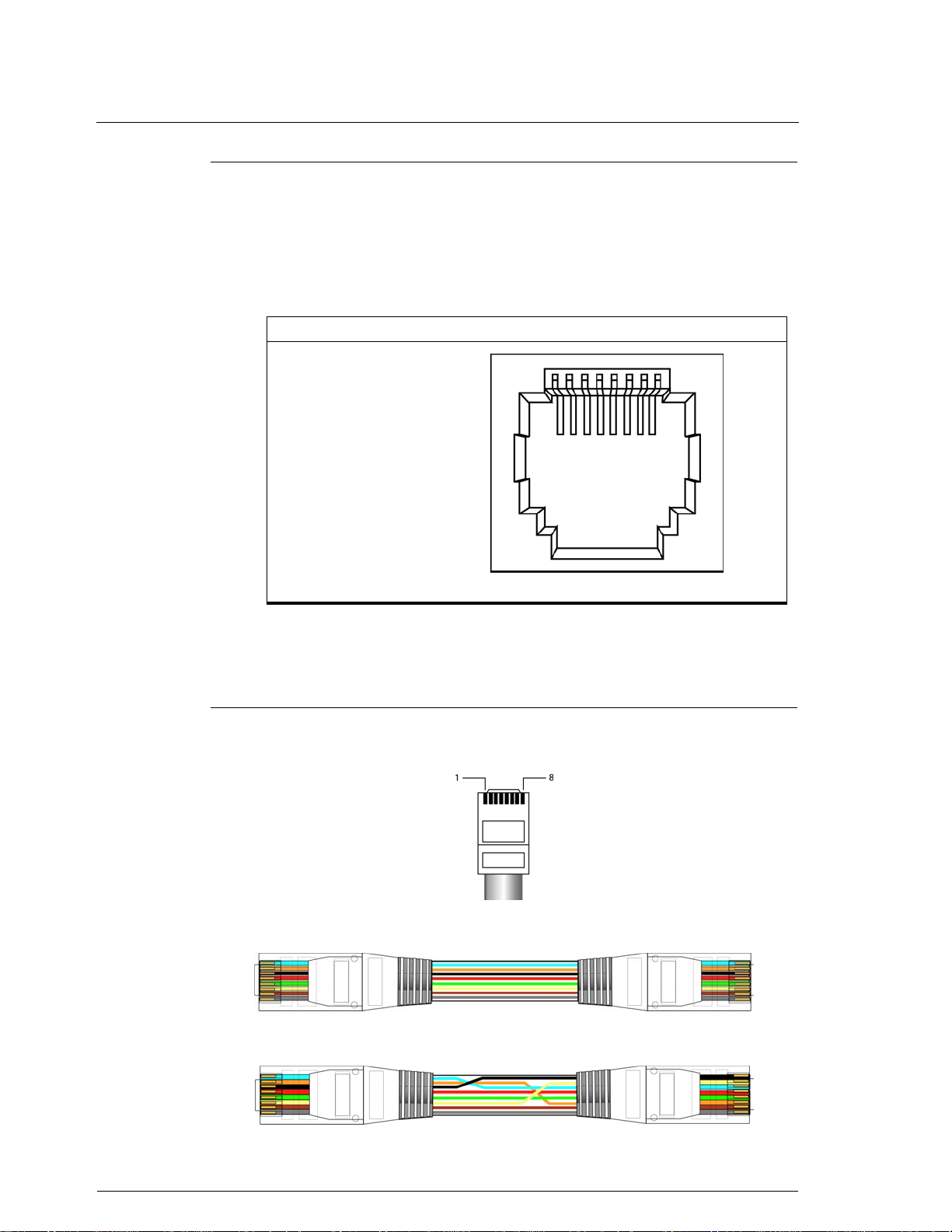
The 10/100 Ethernet ports use standard RJ-45 connectors and Ethernet pinouts with
internal crossovers, as shown by an X in the port name. These ports have their transmit (Tx) and receive (Rx) signals internally crossed so that a straight-through Ethernet cable and an adapter can be attached to the port. The figure below shows the
pinouts.
Pin Label 1 2 3 4 5 6 7 8
1Tx+
2Tx3Rx+
4NC
5NC
6Rx7NC
8NC
Figure B.1 10/100 Ethernet Port Pinout
B.2 Cable Specification
B.2.1 RJ-45
The pin assignment is as follows:
RJ-45 to RJ-45 Straight-through Ethernet Cable:
RJ-45 to RJ-45 Crossover Ethernet Cable:
AG2000Series Software User’s Guide June, 2002 39
Page 44

40 June, 2002 AG2000Series Software User’s Guide
Page 45

APPENDIX C: GLOSSARY
802.1X An IEEE standard for local and metropolitan area networks,
called Port-based Network Access Control. It is used to
securely establish an authenticated association between the
client and the AP.
AP (Access Point) A hardware device, or software used in conjunction with a
computer, that serves as a communications “hub” for
wireless clients and provides a connection to a wired LAN.
An AP can double the range of wireless clients and provide
enhanced security.
Ad-Hoc Mode A client setting that provides independent peer-to-peer
connectivity in a wireless LAN. An alternative set-up is
where PCs communicate with each other through an AP (see
also Infrastructure Mode).
Bandwidth The amount of data that can be transmitted by the network
“information highway”, used as an indication for speed of
data transmission. An Ethernet link is capable of moving 10
million bits of data per second.
Bit The term used to refer to a single unit of data in digital data
communications. It takes 8 bits to make 1 byte, which is a
unit of measurement for computer data.
Bps (Bits per second) Refers to the unit of measurement used for data transmission
speeds over a data communication link.
Bridge A hardware device that passes packets between multiple
network segments using the same networking protocol to
connect the different network segments. Bridge operates at
the hardware layer and has no routing capabilities.
Broadband Any high-bandwidth (see also Bandwidth) data
communication technology that runs at speeds of 200 Kbps
or more and allows combined transmission of voice, data,
and video over a single physical connection. Broadband is in
contrast to narrowband such as traditional 56K analog
modem. DSL, Cable, wireless, and satellite technology are
all different types of broadband technology.
Byte A unit of data equaling to 8 bits (1 Byte = 8 bits).
DHCP (Dynamic
Host Configuration
Protocol) An Internet protocol that allows the DHCP server to
dynamically assign IP addresses to any client workstation
(any device connected to your LAN, such as a PC) for a set
period of time and then sends them back so that they can be
reassigned to other workstations. This feature saves the ISP
and Network Managers from having to manually configure
IP addresses for each PC on the LAN.
DNS (Domain Name
System) A mechanism that translates host domain names into its
numeric IP Address and vice-versa. A domain name is an
easy-to-remember nickname for numerical IP addresses
required by a computer, such as [email protected].
AG2000Series Software User’s Guide June, 2002 41
Page 46

Encapsulation The encapsulating or enclosing data within a particular IP header. Sometimes
the entire frame from one network is placed in the header used by the data link
layer protocol of another network.
Encryption A specific algorithm used to encrypt or encode the data so that it becomes
unreadable to unauthorized users that do not know the decryption key. A good
example of encryption technology is WEP (Wired Equivalent Private).
Ethernet Most popular LAN (Local Area Network) technology that uses CSMA/CD
(Collision Detection) and transfers data between workstations over a variety of
cable types at 10Mbps, also called 10BaseT. Most Ethernet LANs use twisted
pair 10BaseT cables and support both Ethernet as well as Fast Ethernet at
100Mbps (100BaseT).
Firewall A security device (either hardware, software, or a combination of both) that
selectively blocks out or filters unwanted IP traffic from a public network.
Firewall allows the private LAN network to be invisible to the public network
outside, preventing intrusion from unauthorized users.
Hub A hardware device that repeats all data traffic to all CPE (Customer Premises
Equipment) ports. A hub functions as the center of a LAN and all other
network devices on the LAN, including PCs, printers, DSL modem or
Gateways, are connected to the hub through cabling.
Infrastructure Mode A client setting providing connectivity to an AP. As compared to Ad-Hoc
Mode, where PCs communicate directly with each other, clients set in
Infrastructure Mode all pass data through a central AP. The AP not only
mediates wireless network traffic in the immediate neighborhood, but it also
provides communication with the wired network (see also Ad-Hoc Mode and
Access Point).
Internet A massive worldwide network of computer networks interconnecting
thousands of computers and networks around the world and readily accessible
from any computer with a modem or router connection and the corresponding
software.
IP (Internet Protocol) A protocol standard for the Internet. A kind of Internet software that keeps
track of all the addresses on the Internet for different nodes, forwards outgoing
IP traffic, and recognizes incoming IP traffic.
IP Address Numeric address assigned to each machine on the Internet. Consists of four
sets of one, two, or three octal digits separated by periods.
ISP (Internet
Service Provider) The telecommunication company that provides Internet service for the
subscriber. The ISP can be a telephone company, a CLEC or ILEC, or any
other company that provides Internet access to the end user such as AOL,
Earthlink or MSN.
LAN (Local
Area Network) A collection of privately-owned, interconnected computers within a confined
service area.
WEP (Wired
Equivalent Privacy) WEP data encryption is defined by the 802.11 standard to prevent (i) access to
the network by “intruders” using similar wireless LAN equipment and (ii)
capture of wireless LAN traffic through eavesdropping. WEP allows the
administrator to define a set of respective “Keys” for each wireless network
user based on a “Key String” passed through the WEP encryption algorithm.
Access is denied by anyone who does not have an assigned key.
42 June, 2002 AG2000Series Software User’s Guide
 Loading...