

Arecont Vision AV3255PMTIR-H Installation Manual
IR Motorized Model
DN Motorized Model
Installation Manual
Wide Angle Models:
AV1255AM AV3256PM
AV1255AM-H AV3256PM-A
AV1255AMIR AV3256PMIR
AV1255AMIR-H AV3256PMIR-S
AV1255PM-SH AV3256PMIR-SA
AV1255PMIR-SH
AV2255AM AV5255AM
AV2255AM-A AV5255AM-A
AV2255AM-H AV5255AM-H
AV2255AM-AH AV5255AM-AH
AV2255AMIR AV5255AMIR
AV2255AMIR-A AV5255AMIR-A
AV2255AMIR-H AV5255AMIR-H
AV2255AMIR-AH AV5255AMIR-AH
AV2255PMIR-SH AV5255PMIR-SH
AV2255PMIR-SAH AV5255PMIR-SAH
AV2256PM
AV2256PMIR
AV2256PMIR-S
AV3255AM AV10255AMIR
AV3255AM-H AV10255AMIR-H
AV3255AMIR AV10255PMIR-SH
AV3255AMIR-H
AV3255PMIR-SH
Arecont Vision MegaDome® 2 Installation Manual
IR Telephoto Motorized Model
Manual Lens Model
Telephoto Models:
AV2255PMTIR-H
AV2255PMTIR-SH
AV2256PMTIR-S
AV3255PMTIR-H
AV3255PMTIR-SH
AV3256PMTIR
AV3256PMTIR-S
AV5255PMTIR-H
AV5255PMTIR-SH
AV10255PMTIR-H
AV10255PMTIR-SH
Manual Lens Models:
AV1255DN
AV1255DN-H
AV2255DN
AV2255DN-H
AV2256DN
AV3255DN
AV3255DN-H
AV3256DN
AV5255DN
AV5255DN-H
Page | 2 support@arecontvision.com
Arecont Vision MegaDome® 2 Installation Manual
MegaDome® 2 Installation
Contents
Package Contents ................................................................................................................................................... 4
Warranty Information .............................................................................................................................................. 5
Installation ................................................................................................................................................................ 6
Camera Discovery ................................................................................................................................................... 9
Web Interface Quick Guide .................................................................................................................................. 13
SD Card Functionality ........................................................................................................................................... 20
Installation Best Practice ...................................................................................................................................... 24
Wall Mount (MD-WMT2) Installation Instructions (Sold Separately) ............................................................. 25
Junction Box Adapter (SV-JBA) Installation Instruction (Sold Separately) .................................................. 26
Electrical Box Adapter (SV-EBA) Installation Instructions (Sold Separately) .............................................. 30
Pole Mount Adapter (AV-PMA) Installation Instructions (Sold Separately) .................................................. 31
Corner Mount Adapter (AV-CRMA) Installation Instructions (Sold Separately) .......................................... 32
LED Indicators (Camera Signal) ......................................................................................................................... 36
Support ................................................................................................................................................................... 37
Mounting Template ............................................................................................................................................... 38
Page | 3 support@arecontvision.com
Arecont Vision MegaDome® 2 Installation Manual
D
A C B
E F G H I
J
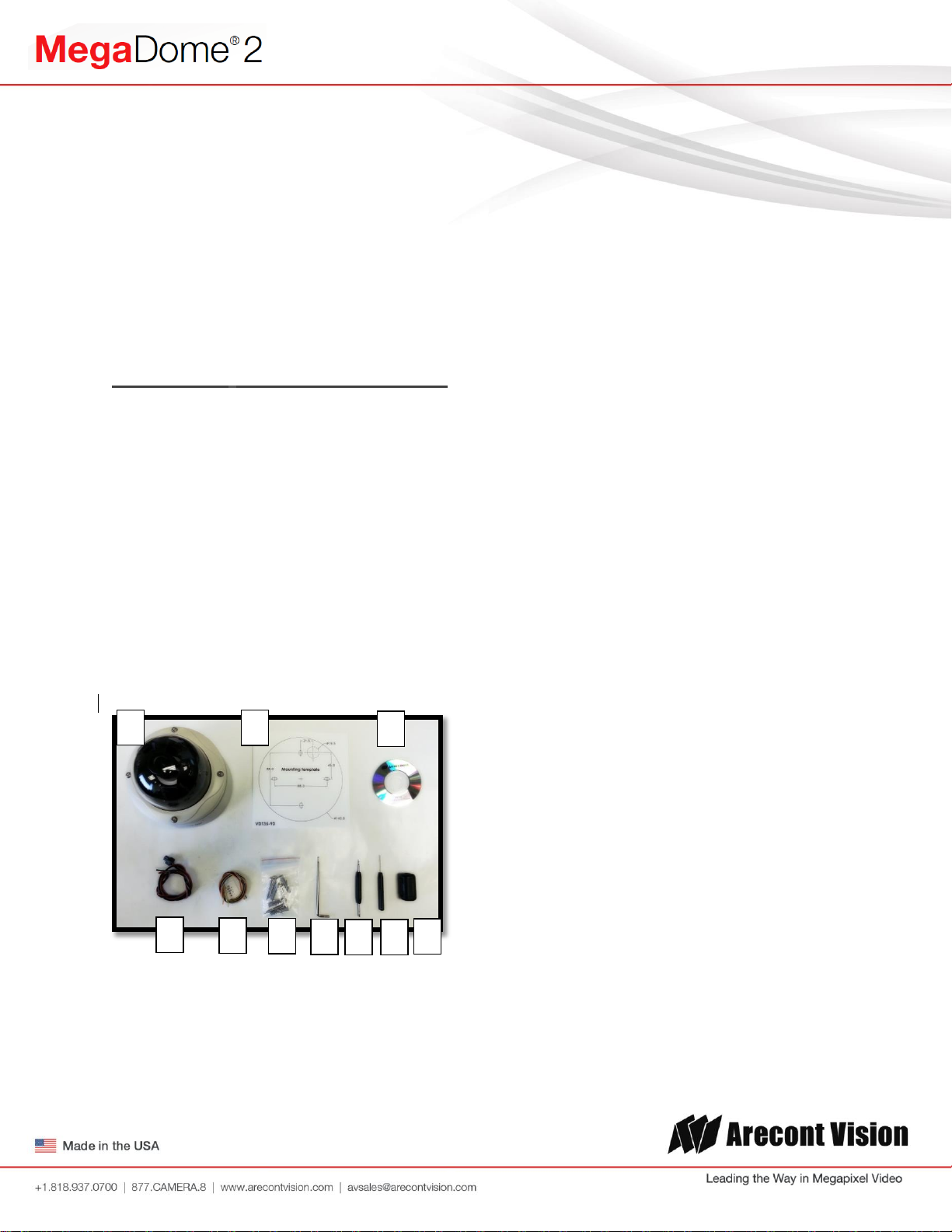
Package Contents
MegaDome® 2 Camera Package:
A. Arecont Vision MegaDome® 2 camera
B. Mounting template
C. CD with AV100 software and user manuals (License Key Required for Recording)
D. AC & DC power cable
E. I/O cable
F. Pack of four (4) screws and four (4) anchors
NOTE: Anchors and screws are good to be used for concrete, wall block and red bricks.
NOTE: Screws by themselves can be used in wood.
G. Security L-Key
H. One double-sided hex key
I. One single-sided hex key
J. Magnetic core
Image 1
Page | 4 support@arecontvision.com
Important Notes:
1. Camera Operating Temperature:
-40°C (-40°F) to +50°C (122°F) w/ Heater (-H models) or WDR Models
-20°C (-4°F) to +50°C (122°F) w/o Heater
2. Wiring methods shall be in accordance with the National Electrical Code/NFPA 70/ANSI, and
with all local codes and authorities having jurisdiction. Wiring should be UL Listed and/or
Recognized wire suitable for the application.
3. Always use hardware e.g. screws, anchors, bolts, locking nuts etc. which are compatible with
mounting surface and of sufficient length and construction to insure a secure mount.
Warranty Information
3 Year Limited Warranty
ARECONT VISION warrants to Purchaser (and only Purchaser) (the “Limited Warranty”), that: (a) each Product shall be free
from material defects in material and workmanship for a period of thirty-six (36) months from the date of shipment (the
“Warranty Period”); (b) during the Warranty Period, the Products will materially conform with the specification in the applicable
documentation; (c) all licensed programs accompanying the Product (the “Licensed Programs”) will materially conform with
applicable specifications. Notwithstanding the preceding provisions, ARECONT VISION shall have no obligation or
responsibility with respect to any Product that (i) has been modified or altered without ARECONT VISION’s written
authorization; (ii) has not been used in accordance with applicable documentation; (iii) has been subjected to unusual stress,
neglect, misuse, abuse, improper storage, testing or connection; or unauthorized repair; or (iv) is no longer covered under the
Warranty Period. ARECONT VISION MAKE NO WARRANTIES OR CONDITIONS, EXPRESS, IMPLIED, STATUTORY OR
OTHERWISE, OTHER THAN THE EXPRESS LIMITED WARRANTIES MADE BY ARECONT VISION ABOVE, AND
ARECONT VISION HEREBY SPECIFICALLY DISCLAIMS ALL OTHER EXPRESS, STATUTORY AND IMPLIED
WARRANTIES AND CONDITIONS, INCLUDING THE IMPLIED WARRANTIES OF MERCHANTABILITY, FITNESS FOR A
PARTICULAR PURPOSE, NON-INFRINGEMENT AND THE IMPLIED CONDITION OF SATISFACTORY QUALITY. ALL
LICENSED PROGRAMS ARE LICENSED ON AN “AS IS” BASIS WITHOUT WARRANTY. ARECONT VISION DOES NOT
WARRANT THAT (I) THE OPERATION OF THE PRODUCTS OR PARTS WILL BE UNINTERRUPTED OR ERROR FREE;
(II) THE PRODUCTS OR PARTS AND DOCUMENTATION WILL MEET THE END USERS’ REQUIREMENTS; (III) THE
PRODUCTS OR PARTS WILL OPERATE IN COMBINATIONS AND CONFIGURATIONS SELECTED BY THE END USER;
OTHER THAN COMBINATIONS AND CONFIGURATIONS WITH PARTS OR OTHER PRODUCTS AUTHORIZED BY
ARECONT VISION OR (IV) THAT ALL LICENSED PROGRAM ERRORS WILL BE CORRECTED.
For RMA and Advance Replacement information visit ArecontVision.com
Arecont Vision MegaDome® 2 Installation Manual
Installation
Mounting the Camera:
1. Remove the camera and hardware from
the box.
2. Using the mounting template, prepare the
mounting surface for camera installation.
NOTE: the 19.5mm diameter hole on the
Mounting template is where the Ethernet
cable will be exiting the MegaDome®2
align accordingly. If using the side conduit
hole, please see step 4 following.
3. Using Security L-key, loosen the four (4)
screws securing the dome cover (Image 2).
Remove the vandal resistant dome cover.
NOTE: Do not remove the screws from the
dome cover.
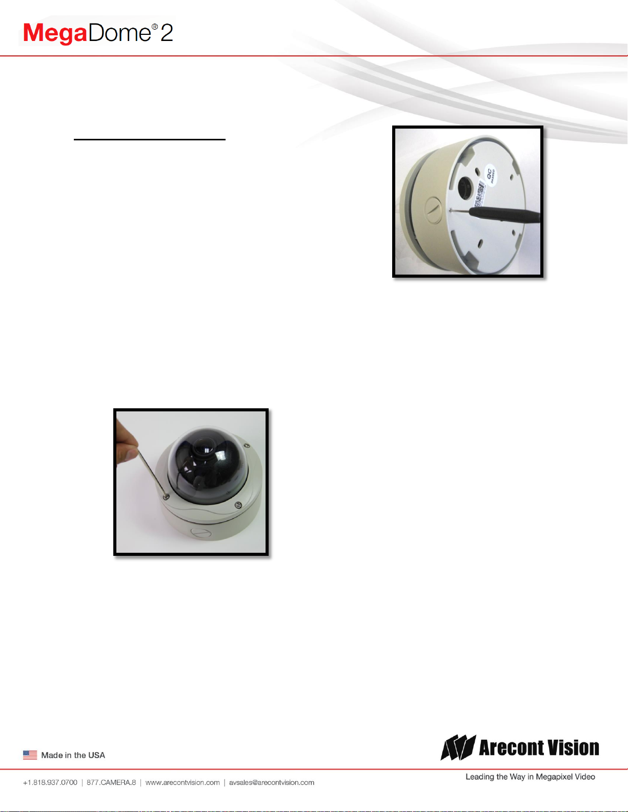
Image 3
Note: Make sure that you install the rubber
gasket on the bottom of the camera to form
a weather tight seal with the mount
surface.
5. Run the Ethernet cable through the gasket
and the hole on the bottom of the camera
(Image 4) or run the cable through the side
conduit and plug it into the RJ45 port.
NOTE: If the camera will be powered via
PoE, please skip to step 6.
Image 2
4. If you are using the side conduit
opening, remove the conduit plug by
first removing the socket set screw
using the provided double-sided hex
key (Image 3).
Page | 6 support@arecontvision.com
6. If the camera will be powered by an AC or
DC power supply, run the supplied power
cable through the gasket and the hole on
the bottom of the camera or run the cable
through the side conduit and connect it to
its respective connector inside the camera
(Image 3).
NOTE: Make sure that your installation of
wires complies with Electrical Code of the
local government where the camera is
installed and that no bare wires are
exposed.
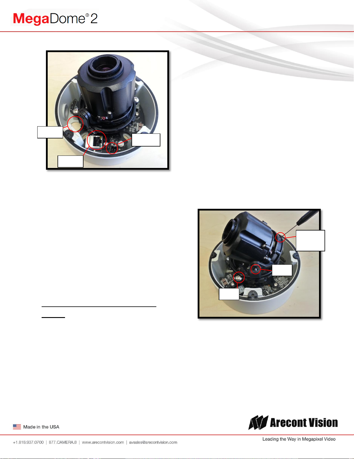
Arecont Vision MegaDome® 2 Installation Manual
HOLE
POWER
RJ-45
Z-Axis
(Yaw)
Tilt
Pan
Image 4
11. To adjust the pan, use a #2 Phillips
screwdriver to loosen the screw as shown
in Image 5.
CAUTION: Do not remove the screw.
12. Adjust the pan as required and tighten the
screw.
13. To adjust the Z-Axis, or yaw, for vertical
wall mounting, loosen the set screw as
shown in Image 5.
NOTE: There are two set screws on opposite
sides; both need to be loosened.
CAUTION: Do not remove the screw.
7. Align the holes in the camera with the
prepared holes on the mounting surface.
Attach the camera to the mounting surface
with the wood screws or any optional
hardware suitable for the mounting
surface.
8. Use appropriate mounting accessories to
ensure a water tight installation. Use of
silicon does not guarantee a water
resistant install.
Adjusting the Tilt, Pan, Z-Axis
(yaw):
9. To adjust the tilt, use a #1 Phillips
screwdriver to loosen the screw on the side
of the plastic lens bracket 1/4 turn (Image
5).
14. Adjust the Z-Axis as required and tighten
the set screws.
Image 5
CAUTION: Do not remove the screw!
10. Adjust lens tilt as required and tighten the
screw.
Page | 7 support@arecontvision.com
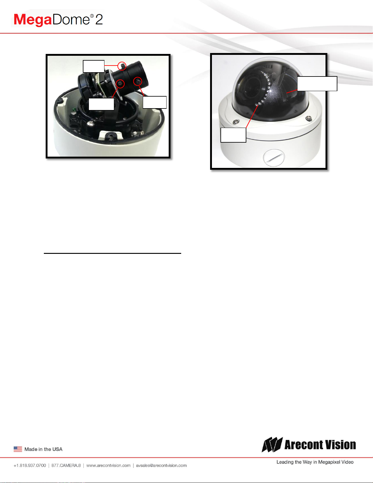
Arecont Vision MegaDome® 2 Installation Manual
Black Liner
IR LEDs
Zoom
Focus
Iris
Image 6
Image 7
15. If the camera is manual lens model, loosen
the three set screws as shown in Image 6
and adjust zoom, focus and iris as needed.
Securing the Vandal Dome Cover:
16. Adjust black liner position to avoid blocking
IR light (if equipped) or the lens as shown
in Image 7.
17. Remove the protective film from the
camera dome.
NOTE: Be careful not to scratch the vandal
dome cover.
18. Secure the vandal dome cover to the
camera using the provided security L-Key.
Page | 8 support@arecontvision.com

Arecont Vision MegaDome® 2 Installation Manual
Camera Discovery
1. Install the AV200 application manager
Software found on the CD.
NOTE: you can download latest version AV200
and installation manual on website
http://www.arecontvision.com/softwares.php
2. Running the Program Installer
To begin the installation of the AV200
software, launch the AVSysSetup.msi
installer (double-click or right click and
chose Open).
After the AV200 is installed, the first time it
is launched the System Setup Wizard will
be started.
Anytime you wish to re run the setup wizard
in the future you can access it from your
desktop by clicking on the icon called
“AVSysSetup”.
The first screen the wizard displays is the
welcome screen.
This will start the installation and is followed
by the installation welcome screen.
Click next and follow the AV200 Setup
Wizard to install the AV200.
3. Adding Cameras with System Setup Wizard
Page | 9 support@arecontvision.com
Click next to continue. Following the
welcome screen, the Accounts screen will
ask to set up Administrator and User
passwords.
Arecont Vision MegaDome® 2 Installation Manual
An Administrator password must be set and
confirmed. The wizard will not allow a blank
password for Administrator and setup
cannot proceed without setting one.
User password can be left blank, allowing
standard users to launch the application
without a password. Click Next to continue.
The next screen in the wizard is the camera
discovery page.
The Refresh button provides an option to
make sure all cameras are found or to
rediscover cameras that were connected
after wizard started.
A range of IP addresses can be defined to
apply to the cameras. If unchanged, the
default address range will be defined by the
IP address currently assigned to the
computer. The second IP range means
cameras within this range will be not
selected by default. No changes will be
made to any cameras not selected (see
next wizard page).
Click Next to continue.
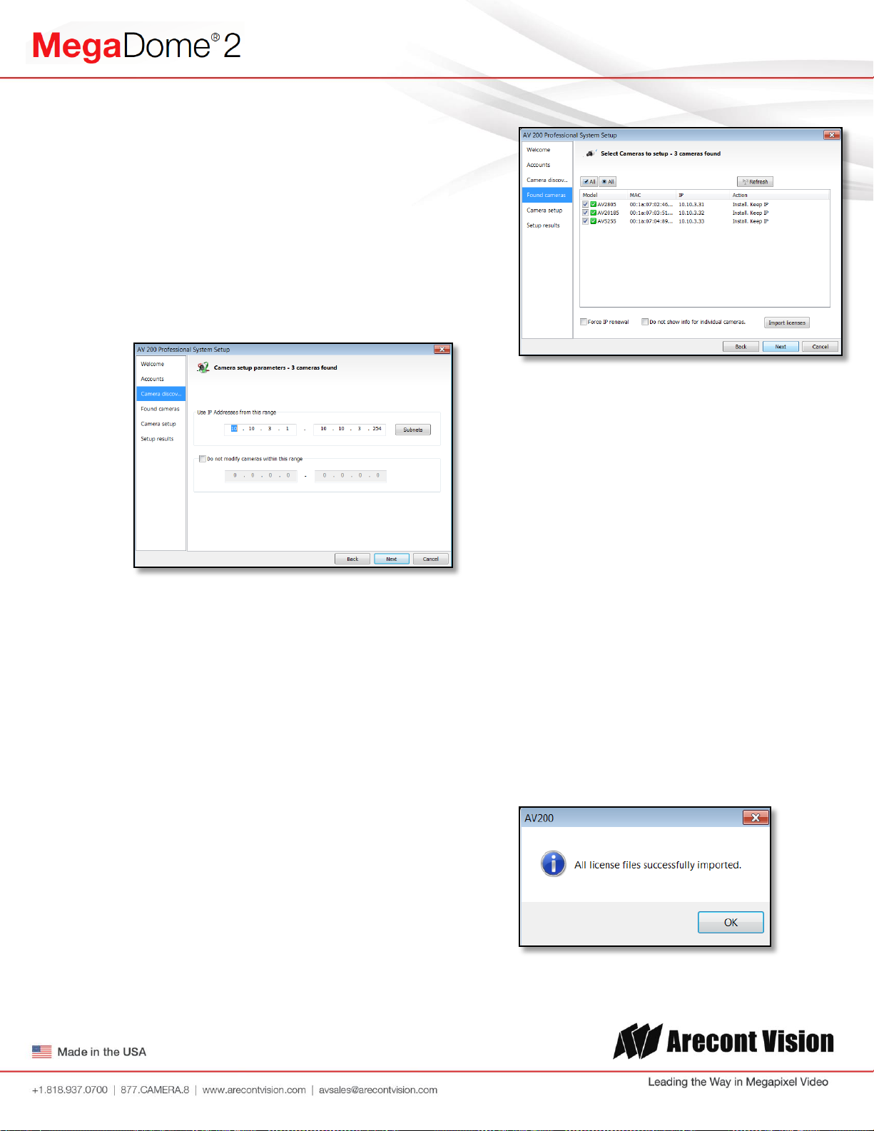
The following screen will display a list of
cameras discovered on the network.
If Refresh is selected, the wizard will display
the discovery screen while it searches for
cameras on the network.
If you have recording licenses click the
button called “Import licenses” to browse to
the folder on your computer the license files
are located. As example if you had licenses
for cameras previously in AV100 software
they will usually be found in the “C:\Program
Files\Arecont Vision\Video
Surveillance\license” directory.
After the license files are successfully
imported you will see the following pop up
display.
Page | 10 support@arecontvision.com
Arecont Vision MegaDome® 2 Installation Manual
Click “OK” and then next to proceed to
discovery.
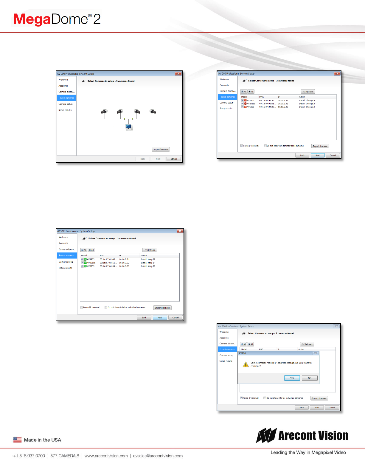
When the discovery process ends, a list of
cameras found on the network will be
displayed.
The camera model, MAC address, current
IP address and status of the camera will be
displayed in the list.
selected cameras check the radio button
labeled Force IP renewal.
If changes are made to the address, the
screen will be followed by an individual
confirmation of the IP address change and
the title of each camera found on the
network.
Individual confirmation screens for each
camera can be skipped, but the software
will change the IP addresses of each
camera found without confirmation.
If the current IP address assigned to the
camera is incompatible with the subnet the
computer running AV200 is assigned to; a
warning icon will be displayed next to the
camera title and the Action message will
display signifying the camera as
inaccessible.
No camera IP addresses are changed at
this stage. To apply an IP change to all
Page | 11 support@arecontvision.com
To change all the addresses and skip to the
end of the set up process, check the radio
button called do not show info for individual
cameras.
Click next and receive a pop-up
confirmation window warning that camera IP
addresses will be changed.
Arecont Vision MegaDome® 2 Installation Manual
Click yes to continue.
If the option for Do not show info for
individual cameras is selected, the wizard
will jump to the summary screen.
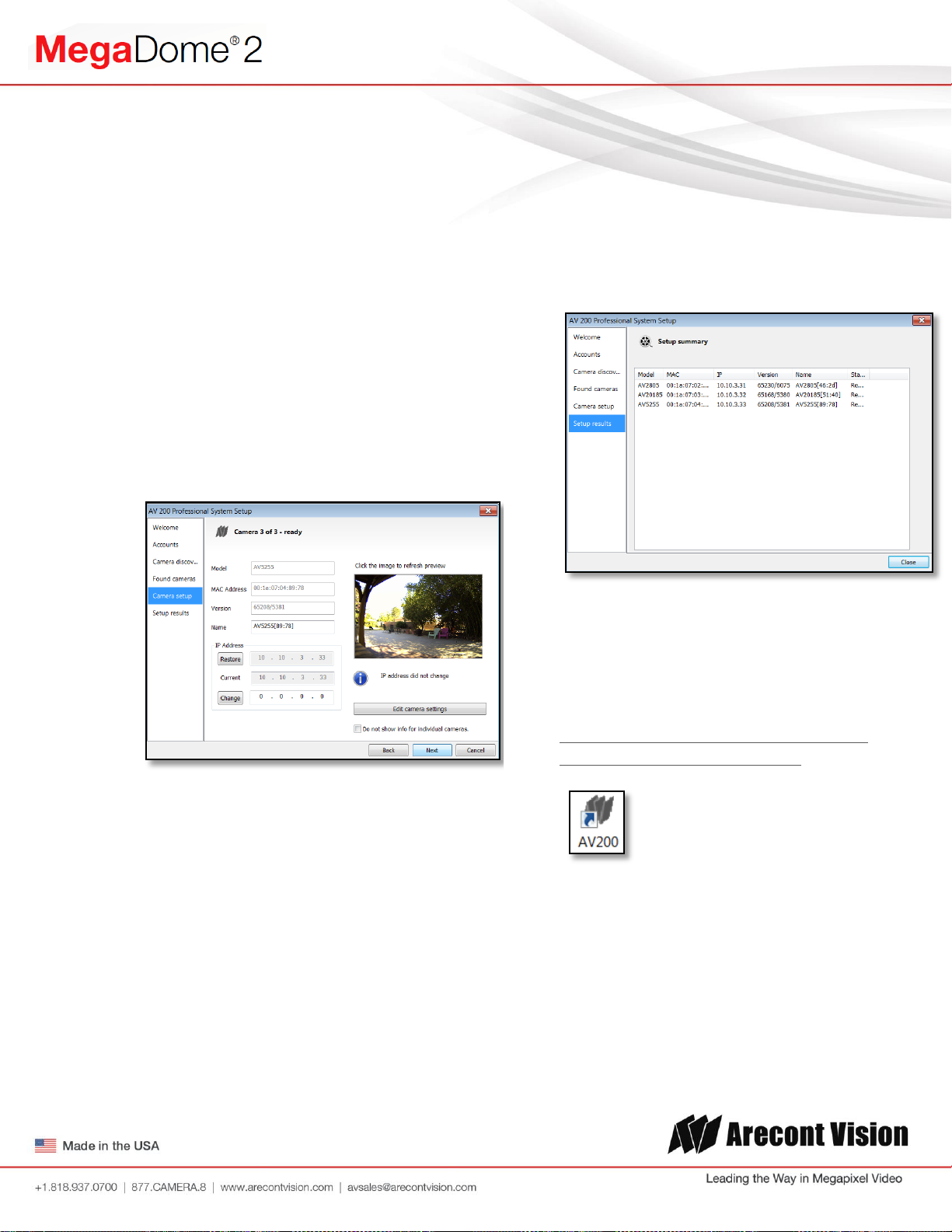
If Do not show info for individual cameras is
not selected, the next series of screens will
display a screen for each camera
discovered.
The Model, MAC address, Firmware/
Hardware version, and a preview image
from the camera will be displayed. There is
an option to change the camera Name or
configure a custom IP address different than
the one currently assigned.
Check the cameras listed on this screen to
confirm that all cameras connected to the
network have been discovered and
successfully installed.
If necessary, click Back to re-run the
discovery process or click next to proceed
to the final setup screen.
There is also an option to choose to restore
the camera to its previous IP address.
To skip any remaining individual camera
information pages, check the radio button
for “do not show info for individual
cameras”.
Select Next to continue.
Following the camera discovery process a
summary of all cameras set up in the
system will be displayed.
The final screen indicates that the system
setup is complete.
Click “Close” to complete the wizard and
exit the software.
4. To launch the AV200 application click on
the desktop icon called “AV200”
NOTE: For more detail instructions, you can
refer to the latest version AV200 installation
manual
Page | 12 support@arecontvision.com
 Loading...