

Arecont Vision AV3155 Installation Manual
Arecont Vision MegaDome® Installation Manual
0 | P a g e
Arecont Vision MegaDome® Installation Manual
H G F E C
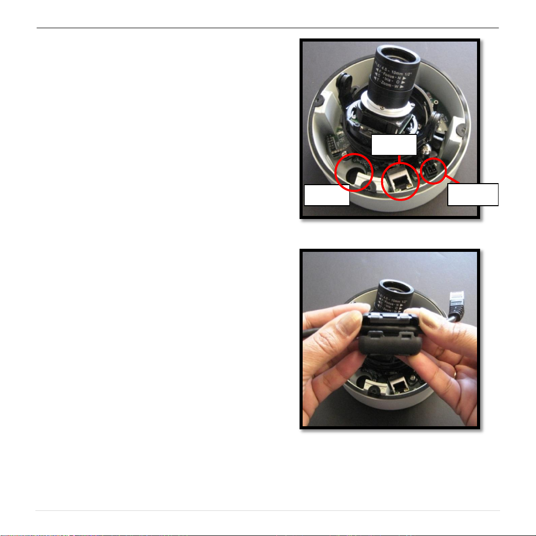
RJ-45
POWER
HOLE
A
D
B
MegaDome® Installation Manual
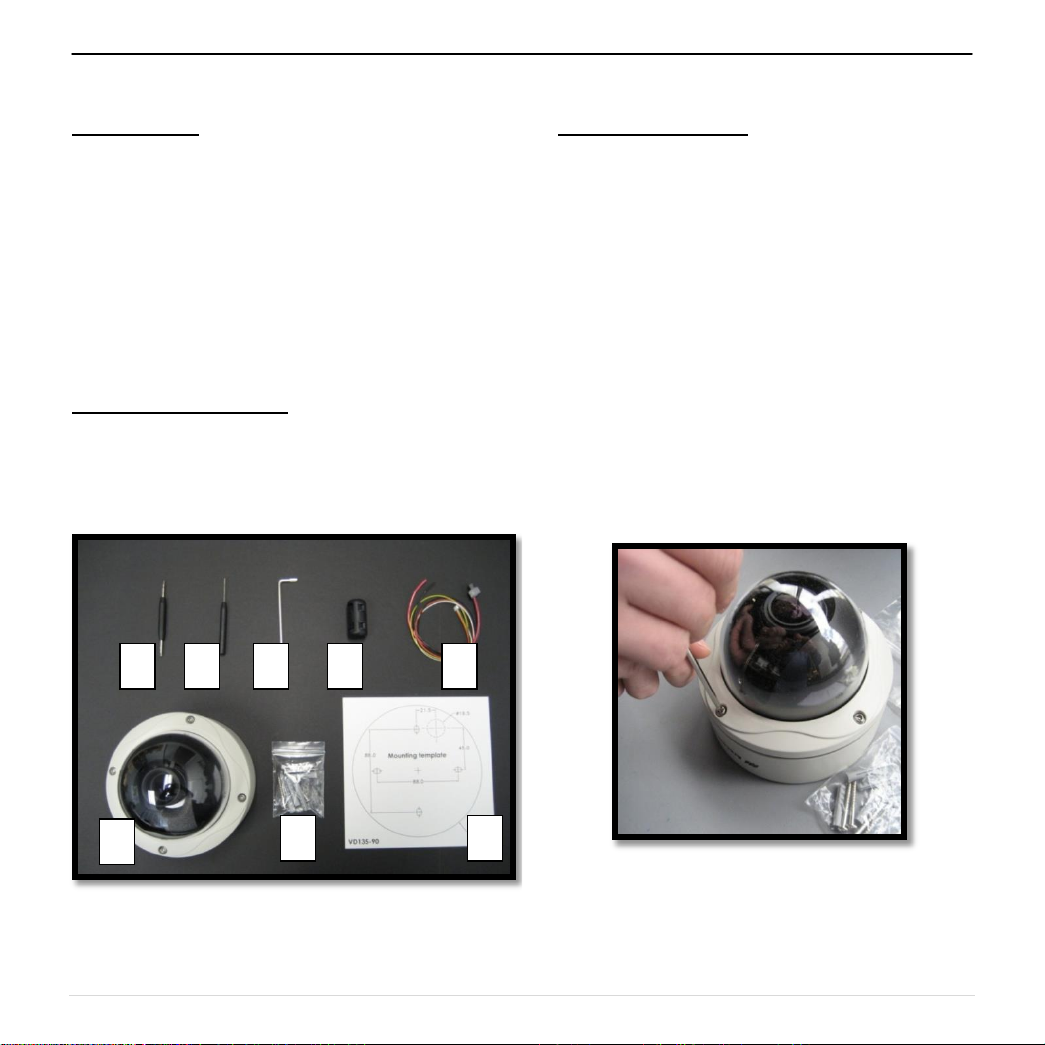
Inside the box:
A. Arecont Vision MegaDome®
B. Mounting template
C. Magnetic core
D. Pack of four (4) wood screws and four (4)
dry wall anchors
E. One double sided hex key
F. One single sided hex key
G. Security L-key
H. Power cable
Not included but needed:
#1 Phillips head screw driver
#2 Phillips head screw driver
Mounting the Camera:
1. Remove camera and hardware from the
box.
2. Using the Mounting template, prepare the
mounting provisions for camera
installation. NOTE: the 19.5mm diameter
hole on the Mounting template is where
the Ethernet cable will be exiting the
MegaDome®, align accordingly. If using
the side conduit hole, please see step 9
below.
3. Using Security L-key, loosen the four (4)
screws securing the dome cover (Image
2). Remove vandal resistant dome
cover. NOTE: Do not remove screws
from the dome cover.
Image 1
Image 2
1 | P a g e
Arecont Vision MegaDome® Installation Manual
HOLE
POWER
RJ-45
4. Run Ethernet cable through the hole on the
bottom of the camera (Image 3) and plug it
into the RJ45 port. NOTE: If the camera will
be powered via PoE, please skip to step 6.
5. If the camera is powered by an outside power
supply, run the supplied power cable through
the hole and connect it to its respective
connector inside the camera (Image 3).
NOTE: Make sure that your installation of
wires complies with Electrical Code of the
local government where the camera is
installed and no bare wires are exposed.
6. Align the holes in the camera with the
prepared holes on the mounting surface.
Attach the camera to the mounting surface
with the wood screws or any optional
hardware suitable for the mounting surface.
7. Install the included magnetic core onto the
Ethernet cable as shown in Image 4. NOTE:
Ensure both tabs are tightly secured.
Image 3
Image 4
2 | P a g e
Arecont Vision MegaDome® Installation Manual
Z-AXIS
(yaw)
TILT
PAN
8. Reference Image 5 for proper positioning of
the magnetic core.
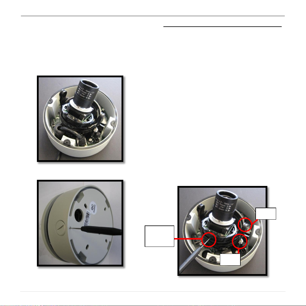
9. If you are using the side conduit opening,
remove the conduit plug by first removing the
socket set screw using one of provided Allen
keys (Image 6).
Image 5
Adjusting the Tilt, Pan, Z-axis (yaw) and Focus:
10. To adjust the tilt, use a #1 Phillips screwdriver
to loosen the screw on the side of the plastic
lens bracket 1/4 turn (Image 7). CAUTION:
Do not remove the screw!
11. Adjust lens tilt as required and tighten the
screw from step 10.
12. To adjust the pan, use a #2 Phillips
screwdriver to loosen the screw as shown in
Image 7.
13. Adjust the pan as required and tighten the
screw from step 2.
14. To adjust the Z-Axis, or Yaw, for vertical wall
mounting, loosen the set screw as shown in
Image 7. NOTE: There are two set screws on
opposite sides; both need to be loosened.
15. Adjust the Z-Axis as required and tighten the
set screw back down.
Image 6
Image 7
3 | P a g e
Arecont Vision MegaDome® Installation Manual
BACK
FOCUS
SET
SCREW
B
BACK
FOCUS
RING
A
BACK
FOCUS
SET
SCREW
BACK
FOCUS
C
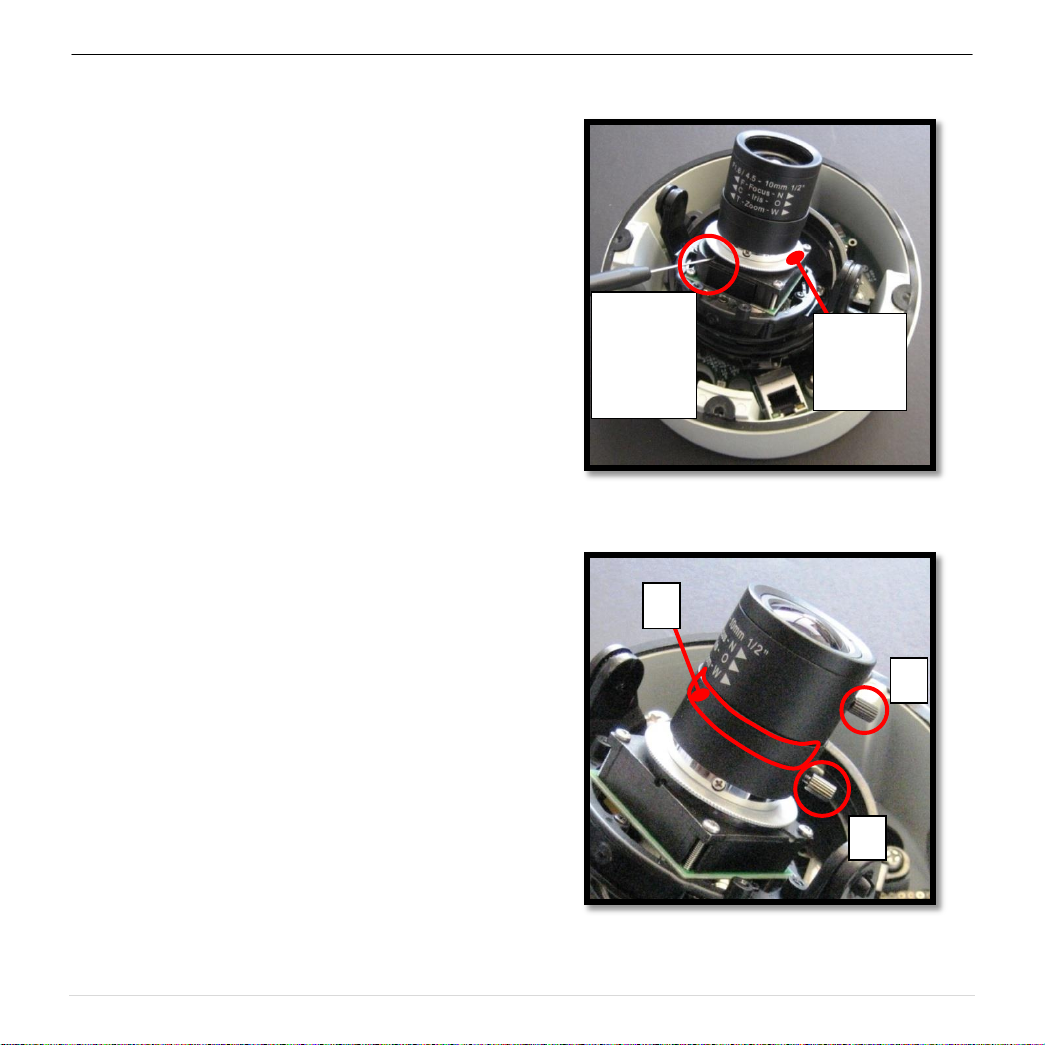
16. To adjust back focus, loosen the two (2) set
screws with the appropriate Allen key as
shown Image 8 (only one of two screw holes
shown). Adjust the silver back focus ring as
needed and tighten down the set screws.
17. To focus the lens, loosen the three set screws
as shown in Image 9 and adjust each as
needed. A adjusts the zoom, B adjusts the
iris (adjustment is the band between A and C
as outlined in red; there is no set screw), C
adjusts the focus.
18. Remove the protective film from the camera
dome. NOTE: be cautious not to scratch the
vandal dome cover.
19. Secure the vandal dome cover to the camera.
Image 8
Image 9
4 | P a g e
Arecont Vision MegaDome® Installation Manual
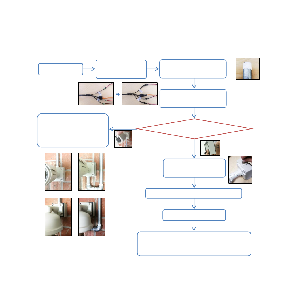
Installation Best Practices
Begin Installation
Wind Vinyl electrical
tape on all cables
Adding Teflon thread sealing
tape to all male threads
Connect ¾” NPT conduit pipe
to junction box adapter
Does conduit pipe go through the wall?
No
Make sure position of conduit
hole is at the lower side
forming a “drip loop” below
the camera using ¾”
Not Recommended!
Not Recommended!
Recommended!
Recommended!
Yes
Tighten all camera screws
and ¾” NPT plugs
Caulk the perimeter of the mounting area
Conduct periodic inspections of the installation. Rust
on the metal parts or screws may result in damage to
camera
End Installation
5 | P a g e
 Loading...