

Page 1
IR Motorized Model
DN Motorized Model
Installation Manual
Wide Angle Models:
AV1255AM AV3256PM
AV1255AM-H AV3256PM-A
AV1255AMIR AV3256PMIR
AV1255AMIR-H AV3256PMIR-S
AV1255PM-SH AV3256PMIR-SA
AV1255PMIR-SH
AV2255AM AV5255AM
AV2255AM-A AV5255AM-A
AV2255AM-H AV5255AM-H
AV2255AM-AH AV5255AM-AH
AV2255AMIR AV5255AMIR
AV2255AMIR-A AV5255AMIR-A
AV2255AMIR-H AV5255AMIR-H
AV2255AMIR-AH AV5255AMIR-AH
AV2255PMIR-SH AV5255PMIR-SH
AV2255PMIR-SAH AV5255PMIR-SAH
AV2256PM
AV2256PMIR
AV2256PMIR-S
AV3255AM AV10255AMIR
AV3255AM-H AV10255AMIR-H
AV3255AMIR AV10255PMIR-SH
AV3255AMIR-H
AV3255PMIR-SH
Page 2
Arecont Vision MegaDome® 2 Installation Manual
IR Telephoto Motorized Model
Manual Lens Model
Telephoto Models:
AV2255PMTIR-H
AV2255PMTIR-SH
AV2256PMTIR-S
AV3255PMTIR-H
AV3255PMTIR-SH
AV3256PMTIR
AV3256PMTIR-S
AV5255PMTIR-H
AV5255PMTIR-SH
AV10255PMTIR-H
AV10255PMTIR-SH
Manual Lens Models:
AV1255DN
AV1255DN-H
AV2255DN
AV2255DN-H
AV2256DN
AV3255DN
AV3255DN-H
AV3256DN
AV5255DN
AV5255DN-H
Page | 2 support@arecontvision.com
Page 3

Arecont Vision MegaDome® 2 Installation Manual
MegaDome® 2 Installation
Contents
Package Contents ................................................................................................................................................... 4
Warranty Information .............................................................................................................................................. 5
Installation ................................................................................................................................................................ 6
Camera Discovery ................................................................................................................................................... 9
Web Interface Quick Guide .................................................................................................................................. 13
SD Card Functionality ........................................................................................................................................... 20
Installation Best Practice ...................................................................................................................................... 24
Wall Mount (MD-WMT2) Installation Instructions (Sold Separately) ............................................................. 25
Junction Box Adapter (SV-JBA) Installation Instruction (Sold Separately) .................................................. 26
Electrical Box Adapter (SV-EBA) Installation Instructions (Sold Separately) .............................................. 30
Pole Mount Adapter (AV-PMA) Installation Instructions (Sold Separately) .................................................. 31
Corner Mount Adapter (AV-CRMA) Installation Instructions (Sold Separately) .......................................... 32
LED Indicators (Camera Signal) ......................................................................................................................... 36
Support ................................................................................................................................................................... 37
Mounting Template ............................................................................................................................................... 38
Page | 3 support@arecontvision.com
Page 4
Arecont Vision MegaDome® 2 Installation Manual
D
A C B
E F G H I
J
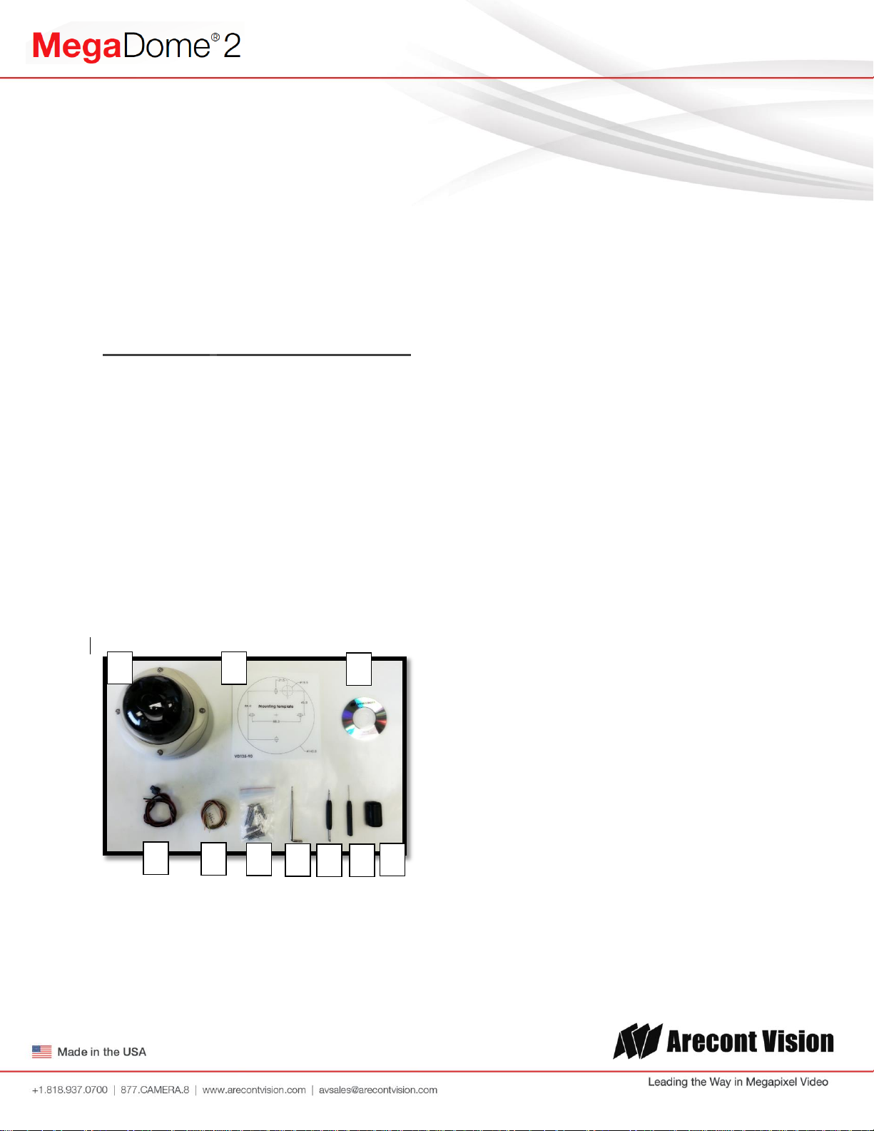
Package Contents
MegaDome® 2 Camera Package:
A. Arecont Vision MegaDome® 2 camera
B. Mounting template
C. CD with AV100 software and user manuals (License Key Required for Recording)
D. AC & DC power cable
E. I/O cable
F. Pack of four (4) screws and four (4) anchors
NOTE: Anchors and screws are good to be used for concrete, wall block and red bricks.
NOTE: Screws by themselves can be used in wood.
G. Security L-Key
H. One double-sided hex key
I. One single-sided hex key
J. Magnetic core
Image 1
Page | 4 support@arecontvision.com
Page 5
Important Notes:
1. Camera Operating Temperature:
-40°C (-40°F) to +50°C (122°F) w/ Heater (-H models) or WDR Models
-20°C (-4°F) to +50°C (122°F) w/o Heater
2. Wiring methods shall be in accordance with the National Electrical Code/NFPA 70/ANSI, and
with all local codes and authorities having jurisdiction. Wiring should be UL Listed and/or
Recognized wire suitable for the application.
3. Always use hardware e.g. screws, anchors, bolts, locking nuts etc. which are compatible with
mounting surface and of sufficient length and construction to insure a secure mount.
Warranty Information
3 Year Limited Warranty
ARECONT VISION warrants to Purchaser (and only Purchaser) (the “Limited Warranty”), that: (a) each Product shall be free
from material defects in material and workmanship for a period of thirty-six (36) months from the date of shipment (the
“Warranty Period”); (b) during the Warranty Period, the Products will materially conform with the specification in the applicable
documentation; (c) all licensed programs accompanying the Product (the “Licensed Programs”) will materially conform with
applicable specifications. Notwithstanding the preceding provisions, ARECONT VISION shall have no obligation or
responsibility with respect to any Product that (i) has been modified or altered without ARECONT VISION’s written
authorization; (ii) has not been used in accordance with applicable documentation; (iii) has been subjected to unusual stress,
neglect, misuse, abuse, improper storage, testing or connection; or unauthorized repair; or (iv) is no longer covered under the
Warranty Period. ARECONT VISION MAKE NO WARRANTIES OR CONDITIONS, EXPRESS, IMPLIED, STATUTORY OR
OTHERWISE, OTHER THAN THE EXPRESS LIMITED WARRANTIES MADE BY ARECONT VISION ABOVE, AND
ARECONT VISION HEREBY SPECIFICALLY DISCLAIMS ALL OTHER EXPRESS, STATUTORY AND IMPLIED
WARRANTIES AND CONDITIONS, INCLUDING THE IMPLIED WARRANTIES OF MERCHANTABILITY, FITNESS FOR A
PARTICULAR PURPOSE, NON-INFRINGEMENT AND THE IMPLIED CONDITION OF SATISFACTORY QUALITY. ALL
LICENSED PROGRAMS ARE LICENSED ON AN “AS IS” BASIS WITHOUT WARRANTY. ARECONT VISION DOES NOT
WARRANT THAT (I) THE OPERATION OF THE PRODUCTS OR PARTS WILL BE UNINTERRUPTED OR ERROR FREE;
(II) THE PRODUCTS OR PARTS AND DOCUMENTATION WILL MEET THE END USERS’ REQUIREMENTS; (III) THE
PRODUCTS OR PARTS WILL OPERATE IN COMBINATIONS AND CONFIGURATIONS SELECTED BY THE END USER;
OTHER THAN COMBINATIONS AND CONFIGURATIONS WITH PARTS OR OTHER PRODUCTS AUTHORIZED BY
ARECONT VISION OR (IV) THAT ALL LICENSED PROGRAM ERRORS WILL BE CORRECTED.
For RMA and Advance Replacement information visit ArecontVision.com
Page 6
Arecont Vision MegaDome® 2 Installation Manual
Installation
Mounting the Camera:
1. Remove the camera and hardware from
the box.
2. Using the mounting template, prepare the
mounting surface for camera installation.
NOTE: the 19.5mm diameter hole on the
Mounting template is where the Ethernet
cable will be exiting the MegaDome®2
align accordingly. If using the side conduit
hole, please see step 4 following.
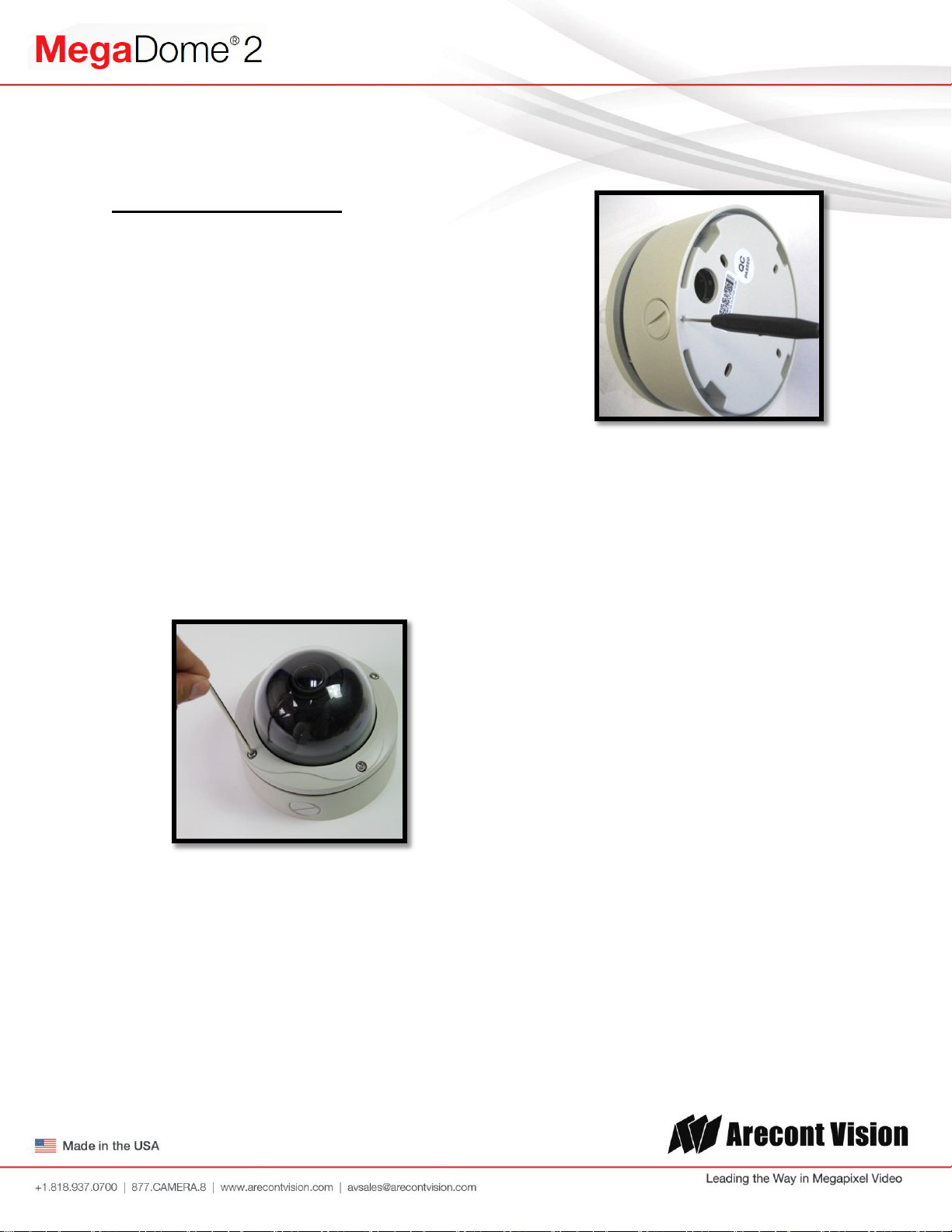
3. Using Security L-key, loosen the four (4)
screws securing the dome cover (Image 2).
Remove the vandal resistant dome cover.
NOTE: Do not remove the screws from the
dome cover.
Image 3
Note: Make sure that you install the rubber
gasket on the bottom of the camera to form
a weather tight seal with the mount
surface.
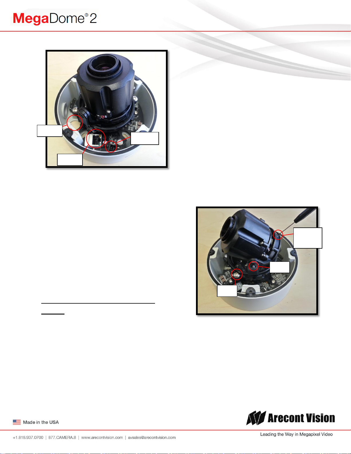
5. Run the Ethernet cable through the gasket
and the hole on the bottom of the camera
(Image 4) or run the cable through the side
conduit and plug it into the RJ45 port.
NOTE: If the camera will be powered via
PoE, please skip to step 6.
Image 2
4. If you are using the side conduit
opening, remove the conduit plug by
first removing the socket set screw
using the provided double-sided hex
key (Image 3).
Page | 6 support@arecontvision.com
6. If the camera will be powered by an AC or
DC power supply, run the supplied power
cable through the gasket and the hole on
the bottom of the camera or run the cable
through the side conduit and connect it to
its respective connector inside the camera
(Image 3).
NOTE: Make sure that your installation of
wires complies with Electrical Code of the
local government where the camera is
installed and that no bare wires are
exposed.
Page 7
Arecont Vision MegaDome® 2 Installation Manual
HOLE
POWER
RJ-45
Z-Axis
(Yaw)
Tilt
Pan
Image 4
11. To adjust the pan, use a #2 Phillips
screwdriver to loosen the screw as shown
in Image 5.
CAUTION: Do not remove the screw.
12. Adjust the pan as required and tighten the
screw.
13. To adjust the Z-Axis, or yaw, for vertical
wall mounting, loosen the set screw as
shown in Image 5.
NOTE: There are two set screws on opposite
sides; both need to be loosened.
CAUTION: Do not remove the screw.
7. Align the holes in the camera with the
prepared holes on the mounting surface.
Attach the camera to the mounting surface
with the wood screws or any optional
hardware suitable for the mounting
surface.
8. Use appropriate mounting accessories to
ensure a water tight installation. Use of
silicon does not guarantee a water
resistant install.
Adjusting the Tilt, Pan, Z-Axis
(yaw):
9. To adjust the tilt, use a #1 Phillips
screwdriver to loosen the screw on the side
of the plastic lens bracket 1/4 turn (Image
5).
14. Adjust the Z-Axis as required and tighten
the set screws.
Image 5
CAUTION: Do not remove the screw!
10. Adjust lens tilt as required and tighten the
screw.
Page | 7 support@arecontvision.com
Page 8
Arecont Vision MegaDome® 2 Installation Manual
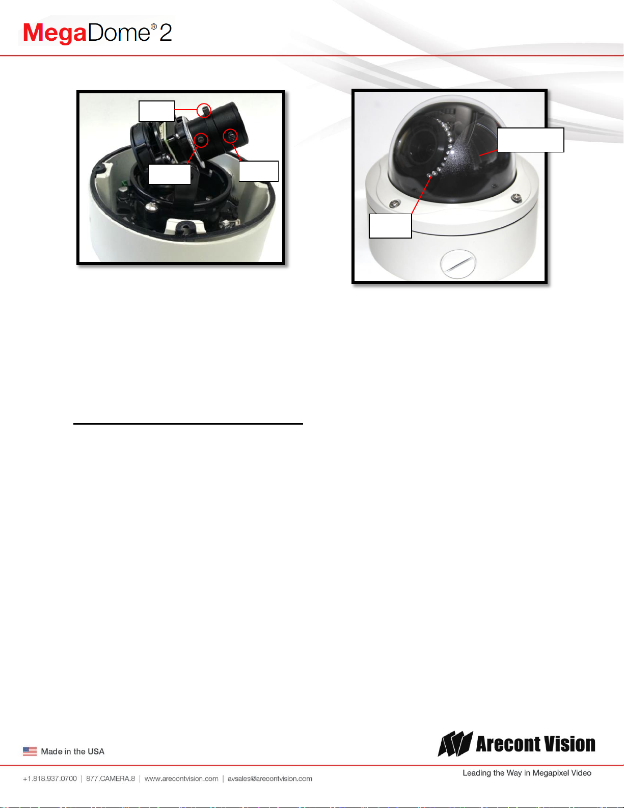
Black Liner
IR LEDs
Zoom
Focus
Iris
Image 6
Image 7
15. If the camera is manual lens model, loosen
the three set screws as shown in Image 6
and adjust zoom, focus and iris as needed.
Securing the Vandal Dome Cover:
16. Adjust black liner position to avoid blocking
IR light (if equipped) or the lens as shown
in Image 7.
17. Remove the protective film from the
camera dome.
NOTE: Be careful not to scratch the vandal
dome cover.
18. Secure the vandal dome cover to the
camera using the provided security L-Key.
Page | 8 support@arecontvision.com
Page 9
Arecont Vision MegaDome® 2 Installation Manual
Camera Discovery
1. Install the AV200 application manager
Software found on the CD.
NOTE: you can download latest version AV200
and installation manual on website
http://www.arecontvision.com/softwares.php
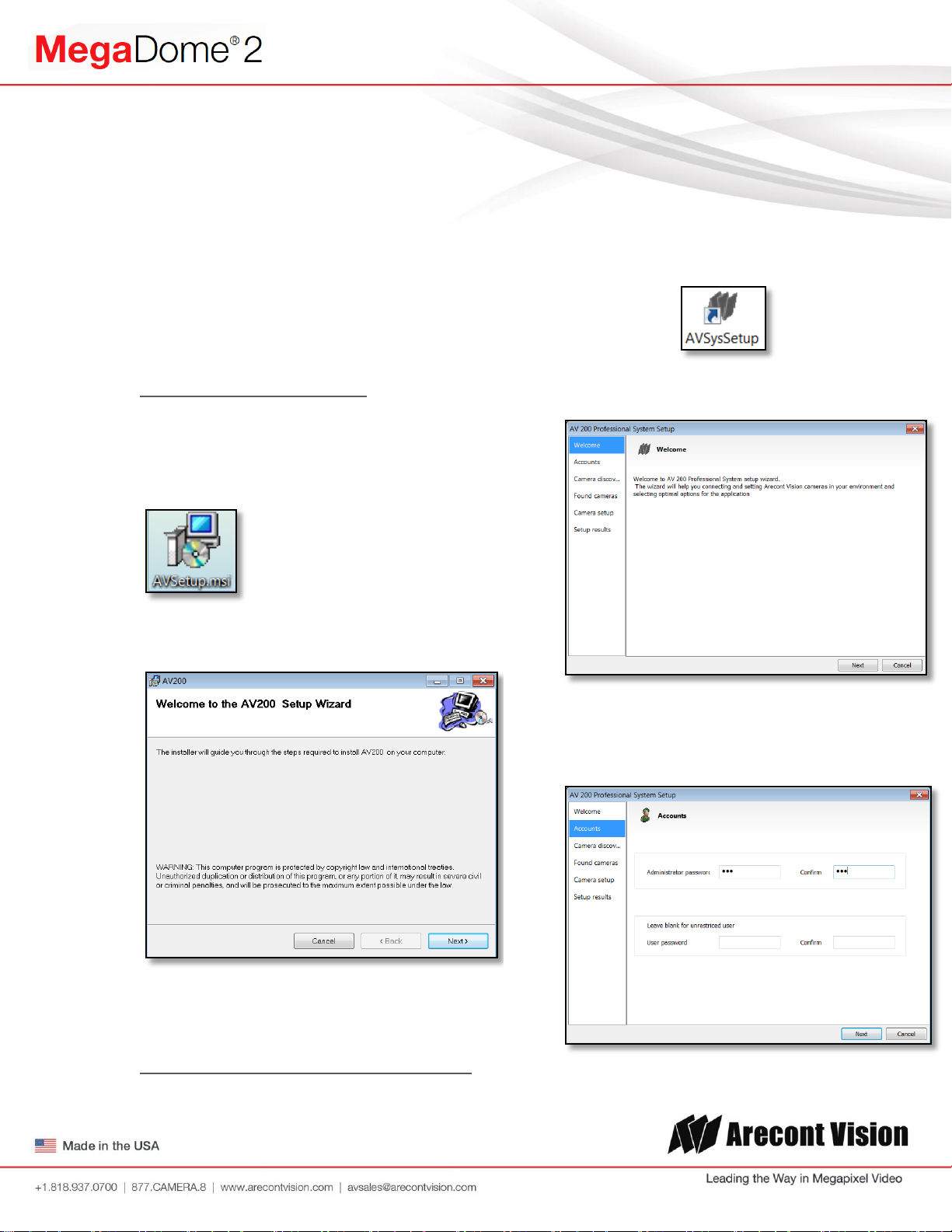
2. Running the Program Installer
To begin the installation of the AV200
software, launch the AVSysSetup.msi
installer (double-click or right click and
chose Open).
After the AV200 is installed, the first time it
is launched the System Setup Wizard will
be started.
Anytime you wish to re run the setup wizard
in the future you can access it from your
desktop by clicking on the icon called
“AVSysSetup”.
The first screen the wizard displays is the
welcome screen.
This will start the installation and is followed
by the installation welcome screen.
Click next and follow the AV200 Setup
Wizard to install the AV200.
3. Adding Cameras with System Setup Wizard
Page | 9 support@arecontvision.com
Click next to continue. Following the
welcome screen, the Accounts screen will
ask to set up Administrator and User
passwords.
Page 10
Arecont Vision MegaDome® 2 Installation Manual
An Administrator password must be set and
confirmed. The wizard will not allow a blank
password for Administrator and setup
cannot proceed without setting one.
User password can be left blank, allowing
standard users to launch the application
without a password. Click Next to continue.
The next screen in the wizard is the camera
discovery page.
The Refresh button provides an option to
make sure all cameras are found or to
rediscover cameras that were connected
after wizard started.
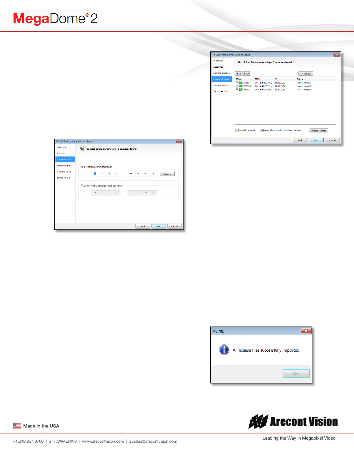
A range of IP addresses can be defined to
apply to the cameras. If unchanged, the
default address range will be defined by the
IP address currently assigned to the
computer. The second IP range means
cameras within this range will be not
selected by default. No changes will be
made to any cameras not selected (see
next wizard page).
Click Next to continue.
The following screen will display a list of
cameras discovered on the network.
If Refresh is selected, the wizard will display
the discovery screen while it searches for
cameras on the network.
If you have recording licenses click the
button called “Import licenses” to browse to
the folder on your computer the license files
are located. As example if you had licenses
for cameras previously in AV100 software
they will usually be found in the “C:\Program
Files\Arecont Vision\Video
Surveillance\license” directory.
After the license files are successfully
imported you will see the following pop up
display.
Page | 10 support@arecontvision.com
Page 11
Arecont Vision MegaDome® 2 Installation Manual
Click “OK” and then next to proceed to
discovery.
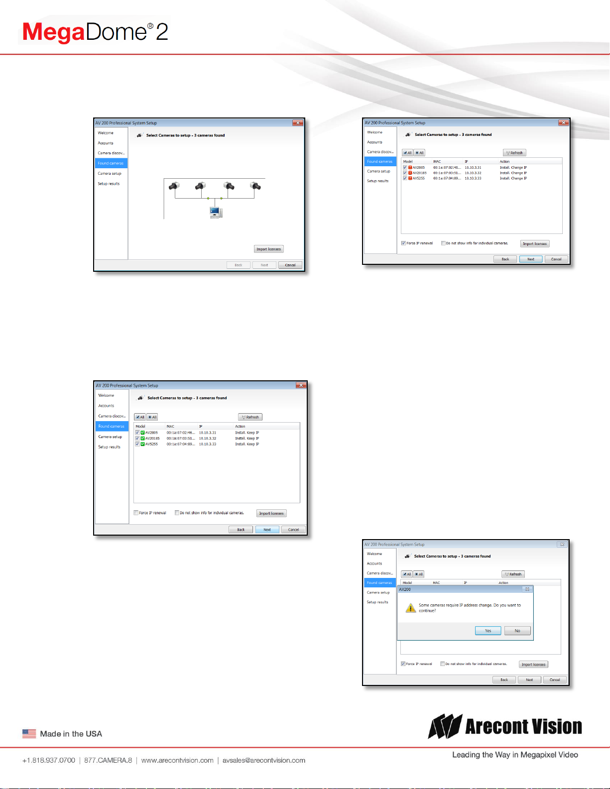
When the discovery process ends, a list of
cameras found on the network will be
displayed.
The camera model, MAC address, current
IP address and status of the camera will be
displayed in the list.
selected cameras check the radio button
labeled Force IP renewal.
If changes are made to the address, the
screen will be followed by an individual
confirmation of the IP address change and
the title of each camera found on the
network.
Individual confirmation screens for each
camera can be skipped, but the software
will change the IP addresses of each
camera found without confirmation.
If the current IP address assigned to the
camera is incompatible with the subnet the
computer running AV200 is assigned to; a
warning icon will be displayed next to the
camera title and the Action message will
display signifying the camera as
inaccessible.
No camera IP addresses are changed at
this stage. To apply an IP change to all
Page | 11 support@arecontvision.com
To change all the addresses and skip to the
end of the set up process, check the radio
button called do not show info for individual
cameras.
Click next and receive a pop-up
confirmation window warning that camera IP
addresses will be changed.
Page 12
Arecont Vision MegaDome® 2 Installation Manual
Click yes to continue.
If the option for Do not show info for
individual cameras is selected, the wizard
will jump to the summary screen.
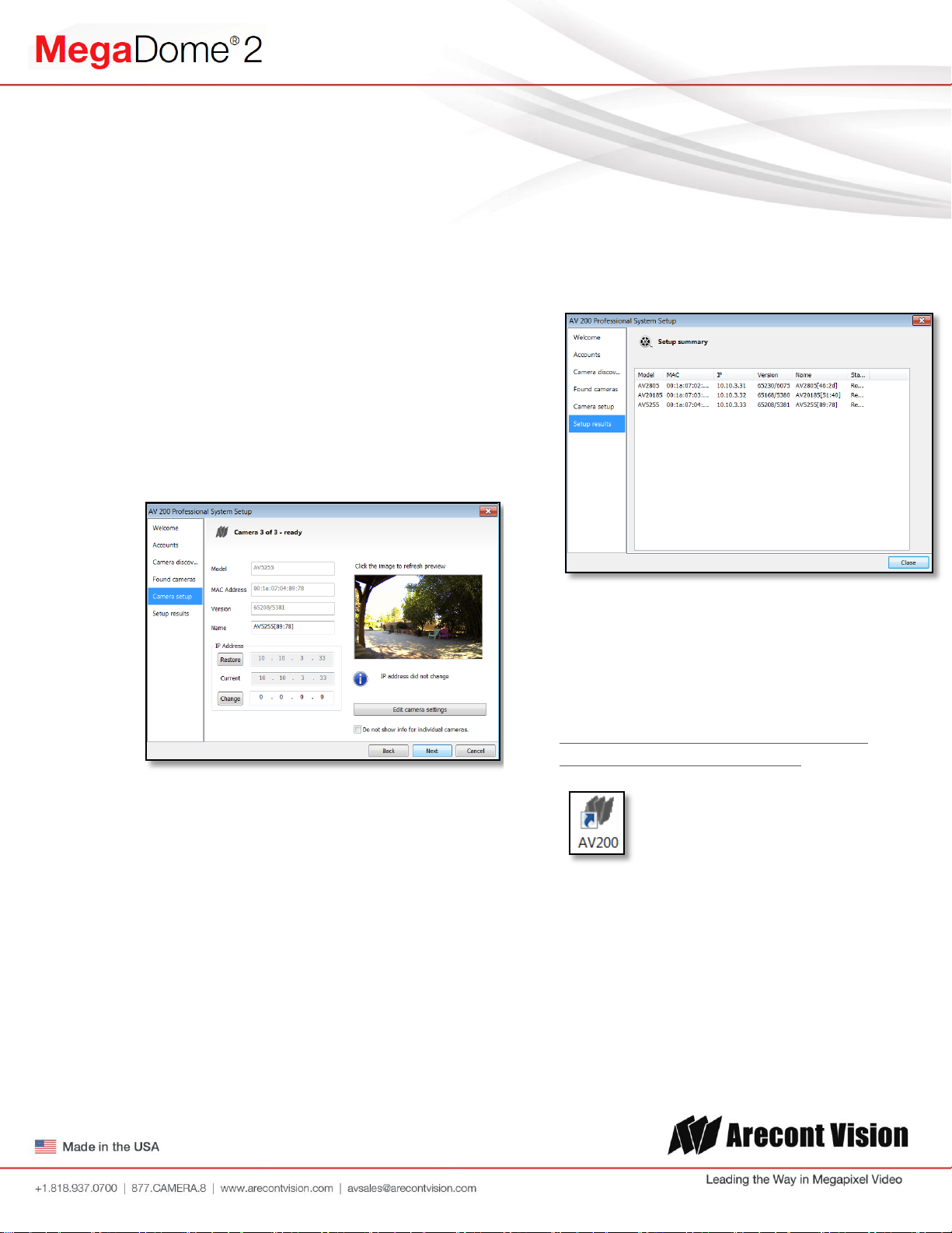
If Do not show info for individual cameras is
not selected, the next series of screens will
display a screen for each camera
discovered.
The Model, MAC address, Firmware/
Hardware version, and a preview image
from the camera will be displayed. There is
an option to change the camera Name or
configure a custom IP address different than
the one currently assigned.
Check the cameras listed on this screen to
confirm that all cameras connected to the
network have been discovered and
successfully installed.
If necessary, click Back to re-run the
discovery process or click next to proceed
to the final setup screen.
There is also an option to choose to restore
the camera to its previous IP address.
To skip any remaining individual camera
information pages, check the radio button
for “do not show info for individual
cameras”.
Select Next to continue.
Following the camera discovery process a
summary of all cameras set up in the
system will be displayed.
The final screen indicates that the system
setup is complete.
Click “Close” to complete the wizard and
exit the software.
4. To launch the AV200 application click on
the desktop icon called “AV200”
NOTE: For more detail instructions, you can
refer to the latest version AV200 installation
manual
Page | 12 support@arecontvision.com
Page 13

Arecont Vision MegaDome® 2 Installation Manual
Web Interface Quick Guide
The web interface page is accessed by typing
in any web browser:
http://ip_address or http://ip_address/index.html
NOTE: For supporting H.264 streaming on
webpage, the recommended browsers are
Internet Explorer and Firefox
NOTE: For more details, you can refer to the
latest version AV Camera Web Page and
Access Protocols manual
http://www.arecontvision.com/softwares.php
1. Menu Navigation
Clicking on any button will cause the menu
displayed on the left side of the page to
jump to the settings section for the selected
function.
2. Image Menu
Brightness controls the overall brightness of
the camera image and works in conjunction
with the exposure controls to maintain the
image brightness
Sharpness controls sharpness and edge
definition of the image. Setting this to higher
levels may make overall image to appear a
bit softer while causing lines and edges in
the image to look smoother
Saturation controls the color saturation of
the image
Rotate Image allows image to be digitally
rotated 0°, 90°, 180°, or 270°
Bandwidth Saving Mode optimizes all
camera settings to provide the best quality
at lowest bitrate possible
Page | 13 support@arecontvision.com
Day/Night settings control operation of this
functionality in Day/ Night model cameras
i. Automatic is default setting enabling
the camera to automatically change
from color (Day) to black and white
(Night) modes as illumination levels
drop off
ii. Day this mode will manually place the
camera in color mode
iii. Night this mode will manually place
the camera in black and white mode
Page 14

Arecont Vision MegaDome® 2 Installation Manual
Switching Level this slider bar and numeric
field control the switching point when the
camera switches from “Day” (color) into
“Night” (black & white) mode. Higher values
cause the camera to stay in “Day” mode at
lower illumination levels, lower values will
cause the camera to switch to “Night” mode
in higher illumination
Toggle Guard this slider bar and numeric
field control the level of brightness required
to switch from “Night” (black & white) into
“Day” (color) mode. Higher values will cause
the camera to stay in “Night” (black & white)
mode longer than lower values as
illumination levels rise. Toggle Guard should
be adjusted to prevent the mode from
toggling between “Night” and “Day” modes
in areas where transitional lighting exists in
the scene
Enable P-Iris this button enables the P-Iris
control function on the camera
Note: If “Enable P-Iris” is unchecked, the iris will
be fully open to the maximum. It may result in
less sharpness and artificial color under strong
light condition as the image shown below.
Binning control operation of the “binning”
function when using a 3, 5, or 10mp camera
model
i. Binning in day mode will place the
camera in binning mode when the
camera is in “Day” mode
ii. Binning in night mode will place the
camera in binning mode when the
camera is in “Night” mode
Downscaling user can downscale their desired
image resolution
Scaling Size sets down-scaling image size
Page | 14 support@arecontvision.com
Page 15

Arecont Vision MegaDome® 2 Installation Manual
3. Video Menu
Show Video type these radio buttons control
selection of display mode
iv. Disable Video when selected this
button the live video won’t show on
the screen
v. MJPEG over HTTP this is the default
browser display option. No plug in is
required as most browsers can
decode MJPEG images
vi. H.264 over RTP/UDP will display
video using H.264. If viewing this way
for the first time you will see the
following prompt to download the
necessary browser plug –in allowing
display of video in the browser using
this compression
4. H.264 Menu
RTSP Unicast port this numeric field allows
configuration of the application port for
RTSP Unicast video streams. Default is 554
valid values that can be set are 1 – 65535
Variable Bitrate Control when this radio
button is selected the camera will maintain
the bit rate based on the Quality setting and
rate limit configured. There may be variation
in the bit rate output from the camera with
additional image compression increase
being applied if the bit rate exceeds the user
defined limit
i. H.264 Quality this numeric field
allows configuration of the default
image compression (also called
Quantization parameter) setting for
H.264 video streaming from the
camera. Higher levels reduce the
Page | 15 support@arecontvision.com
Page 16

Arecont Vision MegaDome® 2 Installation Manual
compression and result in higher
quality images with trade off for
larger file sizes. Lower levels
increase image compression
reducing file sizes with the trade off
for lower quality image detail. Valid
numeric values that can be entered
here are 16 to 36. The configured
value will be constant default unless
rate limit or constant bit rate control
are selected
ii. Enable Rate Limit this radio button
enables operation of the bit rate limit
feature for H.264
iii. Rate limit this numeric field allows
setting the maximum bit rate limit for
Variable bit rate control. Valid values
that can be entered are 0 to 65535
kbps. When active the bit rate will
vary depending on camera
resolution, illumination, and scene
content until it exceeds the
configured limit. When this limit is
exceeded image compression will be
increased in attempt to keep the bit
rate within the configured limit
Constant Bitrate Control when active this
radio button enables the constant bit rate
control feature. Unlike variable bit rate
control option constant bit rate control will
set a hard limit for the bit rate. Image
compression will be set to whatever value
achieves the configured bit rate. This
method of bit rate control can achieve a
more consistent overall bit rate. Image
quality will be dependent on camera
resolution, illumination, and scene content
based on the constant control limit
configured
i. Bitrate this numeric field allows
setting the bit rate value for constant
bit rate control. Valid values that can
be entered are 0 to 65535 kbps
Frames per second this slider bar control
allows setting a frame rate output limit for
the H.264 video stream. Default value is
“Max” minimum fps is 1. Reducing the frame
rate output is another way to control the
bandwidth used for the H.264 video
streaming from the camera trade off is the
obvious reduction of frame rate output at the
camera
5. Focus Menu
Adjusting the Remote Focus and Remote
Zoom
i. To manually adjust zoom, click the
“+20”, “+5”, “+1”, “-20”, “-5”, “-1”
buttons to zoom in and out, adjusting
the field of view
NOTE 1: “+20” zooms in 20x further than
“+1”
NOTE 2: If the “Enable Auto Focus after
zoom” option is checked, the focus will
automatically be adjusted when zoom is
changed.
ii. Set up a focus area (if necessary) by
drawing a rectangle with the mouse
(by left-clicking and dragging the
mouse to a desired zoom size)
Page | 16 support@arecontvision.com
Page 17

Arecont Vision MegaDome® 2 Installation Manual
iii. To automatically adjust focus, choose
“Full-range Focusing” or “Short-range
Focusing” depending on the image
clarity
iv. If the image is completely out of
focus, choose “Full-range Focus” to
scan the full focus range and find the
best focus position.
v. If the image is slightly of out of focus,
choose “Short-rang Focus” to fine
tune and quickly get a precise focus
position to save time.
vi. To manually focus, click the “+20”,
“+5”, “+1”, “-20”, “-5”, “-1” buttons to
fine tune the focus.
6. Network Menu
Default Gateway the gateway IP address for
the local network can be manually
configured in this field
DHCP/ Fixed Selection these radio buttons
allow configuring the camera as either Fixed
IP (manually configured), or DHCP (auto
addressed from local DHCP server) when
selected
Miscellaneous settings allow assignment of
a camera name in the Camera Name: field,
and creating an alternate HTTP access port
in the Second HTTP port: field
7. Motion Detection Menu
IP Address the camera IP address can be
manually configured in this field
Subnet Mask the sub net of the local
network can be manually configured in this
field
Page | 17 support@arecontvision.com
Enable radio button enables the motion
detection feature when selected. When this
button is selected no additional changes
can be made to the other settings in this
menu
Extended radio button enables the
“extended” motion detection from default 64
to 1024 detection zones for enhanced
detection sensitivity
Page 18

Arecont Vision MegaDome® 2 Installation Manual
Zone Size determines the size of the
detection zone grid displayed when motion
detection feature is enabled
Note: if the zone size is set too small for
image sensor pixel resolution the motion
detection grid can be made smaller than the
actual image size. Areas not covered by the
grid will not be monitored for motion
Detail determines the size of each zone
displayed by the motion detection grid
contains sub zones the number of which is
determined by the zone size setting up to
32x32 (pixels). This setting configures the
sensitivity of the motion detection to the size
of objects in the image moving through the
zone. Higher values will trigger motion only
for larger objects moving through the zone,
lower values will cause detection of smaller
objects in the zone (increasing sensitivity to
smaller size objects moving through the
image)
Level threshold determines the sensitivity to
brightness changes between dark and light
objects within each grid zone. As example
“Detail” will set the size of the object being
detected within the zone, “level” sets the
duration that movement must be maintained
to trigger motion detection. Lower settings
can increase false motion alarms caused by
image noise, higher settings will require
more movement to trigger a motion event
Motion Sensitivity, % determines the
sensitivity to sudden overall brightness
changes in the image. This setting can be
useful to prevent false motion alarms due to
sudden exposure changes such as car head
lights from triggering motion detection.
Larger values will disregard larger changes
affecting the entire image, smaller values
Page | 18 support@arecontvision.com
will make motion detection more sensitive to
large changes in the image.
Note: the motion mask setting under the Video
menus requires Enable to be selected as on
before areas can be masked to prevent motion
detection in selected zones
8. Privacy Mask Menu
Enable Privacy Mask this radio button when
selected will enable any privacy masks that
have been configured by the Privacy Mask
function in the Video menu.
Note: masked areas of an image are
transmitted with the mask in place, it is part of
the video and cannot be turned off or removed
from video that is being viewed or recorded
after transmission
9. Administration Menu
Page 19

Arecont Vision MegaDome® 2 Installation Manual
Save all settings to flash will save the
current camera configuration as setting
default
Restore to factory default will restore all
settings to factory default (except the
camera IP address)
Firmware upgrade allows selection and
application of a firmware file to be applied to
the camera
10. SD Menu
*See section below SD Card Functionality
for detailed instructions on this feature
Playback SDcard video allows the user to
choose the specific time of video to
playback
SD Card Recording
- Continuous Recording allows the user
enable continuously recording
- Stop Continuous Recording AND
Enable Event-triggered Recording
allows the user to enable events
recording when network failure, motion
alarm or I/O alarm triggered
NOTE: if the continuous recording is
disabled and no of event recording is
enabled, the SD card will not initiate
recording.
Start/End shows the time frame of the video
being recorded.
11. About Menu
Page | 19 support@arecontvision.com
This menu displays important information
about the camera model being viewed
Page 20

Arecont Vision MegaDome® 2 Installation Manual
SD card
SD Card Functionality
Important notes about this feature:
1. The camera will support class 10 microSD or microSDHC cards up to 32GB Not all SD cards are the same.
Arecont Vision highly recommends using SanDisk Extreme Micro SD cards (or an equivalent substitute) as
these cards have been fully tested without issue. The SanDisk Extreme line is better suited for demanding
applications like constant recording. Typical lower grade SD cards are meant for multimedia applications
and will, at times, have questionable quality and reliability.
2. Recording to the SD card is FIFO (first in first out). The oldest (first) entry is deleted first as new storage
requirements arise. There is no indication when this will happen. Storage time is dependent on a variety of
factors such as SD card size and camera FPS.
3. SD Recording supports video only. Audio is not supported.
1. Insert an SD card into the SD card slot. The
location of SD card slot is shown as image
below
NOTE: if the SD card is installed for the first time,
you will need to reboot the camera
2. To setup SD card features, you can choose
either the Web Interface page or AV200
Software
Web Interface
i. Access the camera’s web interface by typing
in any web browser:
http://ip_address or http://ip_address/index.html
ii. Scroll to the SD Card section
Page | 20 support@arecontvision.com
Page 21

Arecont Vision MegaDome® 2 Installation Manual
1. Input the date and time of the
desired video (must be set
between the Start and End time).
2. Check the “Playback SDcard
video” checkbox to play the video.
iii. Select one of the recording methods:
- Continuous Recording to start
continuously recording
- Stop Continuous Recording AND Enable
Event-triggered Recording to enable
events recording for network failure,
motion alarm and/or I/O alarm trigger
iv. You will see the Start and End times once the
camera starts recording (see image below).
The start time represents the beginning time
of the oldest recording.
AV200
i. To launch the AV200 application click on the
desktop icon called “AV200”
ii. To enable recording to the SD card select the
desired camera and drag it to the workspace
to open a view. From the window select the
SD card drop down menu. Choose:
- Continuous Recording OR
- Event-triggered Recording to enable
events recording for network failure,
motion alarm or I/O alarm
v. To playback recorded video:
Page | 21 support@arecontvision.com
Page 22

Arecont Vision MegaDome® 2 Installation Manual
“SD card”
iii. To launch the SD card playback window click
on the “SD card” icon.
iv. Set play range to full span will set the
playback range to the maximum available on
the SD card.
v. Set playback range will allow the user to
input the playback date and time manually.
vi. Export play will export an .avi file for playback
on most media players.
Page | 22 support@arecontvision.com
Page 23

MD-WMT2
Not Recommended!
SV-JBA
Recommended!
MegaDome® 2
Important Note
How to correctly install MegaDome® 2 on a ROUGH surface wall
Correct Installation:
Please install the MegaDome® 2 with wall
mount, (MD-WMT2) and junction box adapter
(SV-JBA) to avoid water leakage risk on
ROUGH surface wall surface as shown in
Image 15.
Inappropriate Installation:
Attaching the MegaDome® 2 directly onto a
ROUGH wall surface may result in water
leakage see Image 16!
Image 15
Image 16
NOTE: Water damage from improper
installation is not covered by the warranty!
Page 24

No
Begin Installation
Wind Vinyl electrical
tape on all cables
Adding Teflon thread sealing
tape to all male threads
Does conduit pipe go
through the wall?
Make sure position of conduit hole is at the lower side
galvanized or flex conduit and appropriate fittings
Connect ¾” NPT conduit
pipe to junction box adapter
Yes
Tighten all camera
NPT plugs
Caulk the perimeter of
the mounting area
Conduct periodic inspections of the installation.
damage to camera
End Installation
Not Recommended!
Not Recommended!
Recommended!
Recommended!
Installation Best Practice
forming a “drip loop” below the camera using ¾”
screws and ¾”
Rust on the metal parts or screws may result in
Page 25

Arecont Vision MegaDome® 2 Installation Manual
B
E D C A F
Wall Mount (MD-WMT2) Installation Instructions (Sold
Separately)
Caution:
MD-WMT2 only fits with SV-JBA and SV-EBA
but not with the older MD-JBA and MD-EBA!
Inside the box:
A. Wall mount
B. Top shield
C. Mounting template
D. One double-sided hex key
E. Pack of four (4) machine screws (#8-32
½”)
F. Pack of four (4) screws and four (4)
anchors
Not included but needed:
G. #2 Phillips head screwdriver
Image 17
1. Remove the wall mount and hardware
from the box.
Image 18
2. Using the mounting template, prepare
the mounting surface.
3. Attach wall mount to the wall using
screws or any optional hardware
4. suitable for the mounting surface.
5. Install top shield on the wall mount as
shown in image 18.
6. Fasten the socket set screw using the
double-side hex key (D).
7. Run the Ethernet cable and outside
power cable (if necessary) through the
wall mount.
8. For installation of the camera, please
reference “Mounting the Camera.”
Page | 25 support@arecontvision.com
Page 26

B C A D E
Junction Box Adapter (SV-JBA) Installation Instruction
(Sold Separately)
Caution:
SV-JBA should always be used in conjunction
with a wall mount, MD-WMT2, for outdoor
installation.
SV-JBA will only fit with the MD-WMT2 wall
mount. It does not fit the camera dome or older
wall mount MD-CMT!
Inside the box:
A. Junction Box Adapter
B. Pack of four (4) machine screws (#8-32
½”)
C. One double-sided hex key
D. Pack of four (4) screws and four (4)
anchors
E. Mounting template
Not included but needed:
F. #2 Phillips head screwdriver
G. Wall Mount, MD-WMT
H. ¾” NPT Conduit (if necessary)
Image 19
1. Remove junction box adapter and
hardware from the box.
Image 20
2. Remove the conduit plug by first
removing the socket set screw using the
provided hex key (C).
3. Attach the junction box adapter to the
wall using screws or any optional
hardware suitable for the mounting
surface.
4. Attach the wall mount to junction box
adapter then attach cap to the wall
mount as shown in Image 20.
5. Connect ¾” NPT Conduit to the junction
box adapter.
6. Run Ethernet cable and outside power
cable (if necessary) through the
Junction Box Adapter and Wall Mount.
7. For installation of the camera, please
reference “Mounting the Camera.”
Page 27

E
C
H
G
D
B
A
I
F
Pendant Mount (MD-CMT) Installation Instructions (Sold
Separately)
Inside the box
A. Top shield
B. Pendant Mount
C. Mounting template
D. Pack of four (4) small machine screws
(#8-32 ½”)
E. Pack of four (4) machine screws
F. Pack of four (4) screws and four (4)
anchors
G. One double-sided hex key
H. Small square rubber gasket
I. Large round rubber gasket
Not included but needed:
J. #2 Phillips head screwdriver
Image 21
1. Remove Pendant Mount and hardware
from the box.
Image 22 Image 23
8. Using the mounting template, prepare
the mounting surface for camera
installation.
9. Place small gasket onto pendant mount
shown in image 22.
10. Attach the top shield to the pendant as
shown in Image 23 using four machine
screws (E) provided.
11. Install the large round rubber gasket
onto the pendant as shown in image 23.
Be sure to align the holes appropriately.
12. Run the Ethernet cable and outside
power cable (if necessary) through the
Pendant.
13. Attach the pendant to the ceiling using
the four wood screws provided or any
optional hardware suitable for the
mounting surface.
14. For installation of the camera, please
reference “Mounting the Camera.”
Page 28

A
MD-CAP
1 ½” Coupling
1 ½” Pipe
1 ½” Flange
B
Wall Mount Cap (MD-CAP) Installation Instructions
(Sold Separately)
Inside the box:
A. Wall Mount Cap (MD-CAP)
B. Pack of four (4) machine screws
Not included but needed:
C. 1½” NPT pipe nipple
D. 1½” NPT coupling
E. 1½” NPT flange
F. #2 Phillips head screwdriver
Image 24
1. Remove the wall mount cap from the
box.
2. Assemble the wall mount cap, 1½”
coupling, 1½” pipe nipple and 1½”
flange as a pendant Mount shown in
image 25.
3. Run the Ethernet cable and outside
power cable (if necessary) through the
pendant.
4. Attach the pendant to the ceiling using
four wood screws or any optional
hardware suitable for the mounting
surface
5. For installation of the camera, please
reference “Mounting the Camera.
Image 25
Page 29

B C A
D
Lever
Screw
Support
Arm
Flush Mount Adapter (MD-FMA) Installation Instructions
(Sold Separately)
Inside the box:
A. white trim ring
B. Flush mount adapter
C. Mounting template
D. Pack of four (4) machine screws (#8-
32 ½”) and one (1) eyelet
Not included but needed:
E. #2 Phillips head screwdriver
Image 26
1. Remove the flush mount adapter, trim
ring and hardware from the box
2. Attach the dome to the flush mount
adapter as shown in Image 27. Please
reference “Mounting the Camera,” if
needed.
3. Using the mounting template, cut a hole
in surface for mounting.
4. Insert the flush mount adapter into the
hole.
5. Tighten the “lever screws” until the flush
mount adapter is snuggly installed, as
shown in Image 27. The “Support Arm”
will ride down the screw to compress the
mounting surface. NOTE: Do not overtorque the lever screws.
6. Attach the trim ring to the flush mount
adapter by rotating clockwise as show in
Image 28.
Image 27
Image 28
Page 30

MD-WMT2
Bracket holes
A
B
Junction box
adapter holes
Electrical Box Adapter (SV-EBA) Installation Instructions
(Sold Separately)
Inside the box:
A. Electrical Box Adapter
B. Pack of four (4) machine screws (#8-
32 7/16”)
Image 30-1 Single gang box
Image 29
Not included but needed:
Common electrical box, such as single
gang box, double gang box, or square
electrical boxes shown in Image 30-1~4.
1. Remove the electrical box adapter and
hardware from the box.
2. Attach the wall mount bracket to the
electrical box adapter.
3. Attach adapter to electrical box.
Image 30-2 Double gang box
Image 30-3 Square box
Image 30-4 Square box
Page 31

Arecont Vision MegaDome® 2 Installation Manual
A B C
D
Pole Mount Adapter (AV-PMA) Installation Instructions
(Sold Separately)
Inside the box:
A. Pole Mount Adapter
B. 2x Small Steel Straps
C. 2x Large Steel Straps
D. Pack of four (4) machine screws (#8-32
5/8”)
Not included but needed:
SV-JBA (Junction box adapter)
MD-WMT2 (MegaDome® wall mount)
Image 31
4. Run the Ethernet cable and outside power
cable (if necessary) through the Junction
Box Adapter and MegaDome® wall
mount, MD-WMT2.
5. Attach MegaDome® wall mount, MDWMT2, to Pole Mount Adapter as shown in
Image 33.
6. Use the supplied two steel straps to attach
the Pole Mount Adapter to the pole and
tighten the compression screws as shown
in Image 33.
7. Attach the dome to wall mount adapter.
Please reference “Mounting the Camera,” if
needed.
1. Remove Pole Mount Adapter, steel Straps
and hardware from the box.
2. Attach SV-JBA (Junction Box Adapter) to
Pole Mount Adapter as shown in Image
32.
3. Remove the conduit plug on Junction box
adapter and connect ¾” NPT Conduit to
Junction Box Adapter shown in Image 32-
1.
NOTE: Use silicon or water pipe seal tape
to make sure no water leakage between
conduit pipe and junction box adapter.
Page | 31 support@arecontvision.com
Image 32 Image 32-1
Image 33
Page 32

A
B
Wall
Mount
Corner Mount Adapter (AV-CRMA) Installation Instructions
(Sold Separately)
Inside the box:
A. Corner Mount Adapter
B. Pack of four (4) machine screws (#8-32
5/8”), twelve (12) screws, twelve (12)
anchors, and twelve (12) washers
Not included but needed:
SV-JBA (Junction box adapter)
MD-WMT2 (MegaDome® wall mount)
Image 34
1. Remove Corner Mount Adapter and
hardware from the box.
2. Attach SV-JBA (Junction Box Adapter)
to Corner Mount Adapter as shown in
Image 35.
3. Remove the conduit plug on Junction
box adapter and connect ¾” NPT
Conduit to Junction Box Adapter shown
in Image 35-1.
NOTE: Use silicon or water pipe seal tape
to make sure no water leakage between
conduit pipe and junction box adapter.
4. Run the Ethernet cable and outside
power cable (if necessary) through the
Junction Box Adapter and MegaDome®
wall mount, MD-WMT2.
5. Attach MegaDome® wall mount, MDWMT2, to Corner Mount Adapter as
shown in Image 36.
6. Using the screws provided (or other
hardware) to attach the Corner Mount
Adapter to an exterior 90° corner wall.
7. Attach the dome to wall mount adapter.
Please reference “Mounting the
Camera,” if needed.
Image 35 Image 35-1
Image 36
Page 33

Arecont Vision MegaDome® 2 Installation Manual
C
A
Heater
Connector
Heater
B
Heater Kit MD2-HK Installation Instructions
(Accessory Sold Separately, except –H Models)
Note: Heater kit MD2-HK is not available on
MegaDome® 2 WDR models!
Inside the box:
A. Heater
B. Two (2) plastic stand-offs
C. Two (2) screws
Not included but needed:
D. #1 Phillips head screwdriver
Image 37
1. Remove the heater kit from the box.
2. Connect the heater cable to the connector
on PCB as shown in Image 39. Red is
positive (+) cable.
3. With the heater element facing away
from the main board in the camera,
align the two (2) holes on the heater
board with the two holes on gimbal
base shown in Image 38.
4. Attach the heater board with the
standoff on gimbal base as shown in
Image 39.
Image 38
NOTE 1: MegaDome® 2 Heater, MD2-HK, uses
2.28 watts which is different from the
MegaDome® Heater. (MD-1HK is 10 watts)
NOTE 2: Unlike the MegaDome® Heater (MD1HK), MegaDome® 2 Heater (MD2-HK) doesn’t
need external power input.
Page | 33 support@arecontvision.com
Image 39
Page 34

Electrical Characteristics:
Min
Max
Input voltage (V)
ON
2.9
6.3
(measured between + and –
terminals)
OFF 0 1.3
Output current (mA)
ON - 50
(measured between + and – terminals)
Applied Voltage Rage: 0 - 80V
OFF - 0.1
Orange
OUT +
Yellow
OUT –
White
IN +
Black
IN -
A
I/O
Connector
MegaDome® 2 I/O Cable Connection
Inside the box:
A. I/O Cable
Image 40
Not included but needed:
B. Flat head screwdriver
1. To use the I/O ports of the
MegaDome®, run the I/O cable through
the hole in the bottom of the camera and
plug it into the connector as shown in
Image 41.
NOTE: The connection is a little stiff so
be sure to apply enough pressure to
connect it; using a flat head screw driver
to push it in is recommended.
Image 41
NOTE: Both the input and the output are
electrically isolated from the rest of the
camera’s electrical circuitry via general-purpose
photo couplers. The input is additionally
protected with a serial 250 Ohm resistor and a
debouncing circuit. Duration of any input signal
should be at least 5ms to comply with the
requirements of the debouncing circuit.
Table 1
Table 2
Page 35

Arecont Vision MegaDome® 2 Installation Manual
Line In
Microphone In
Line Out
Microphone
MegaDome® 2 Audio Cable Connection (-A Models only)
Inside the box:
A. Three (3) 3.5mm mono in-line jacks
Image 42
Not included but needed:
B. Flat head screwdriver
C. Microphone, line-in Device, or speaker
1. Run the audio cable connection jack cables
through the hole in the bottom of the
camera and connect them to the connectors
on the circuit board as shown in Image 43.
D. Connect a mono analog microphone to
MICIN (Microphone In), connect the
line-in signal to LINEIN (Line In),
connect an active speaker with a built-in
amplifier to LOUT (Line Out) via the inline jack as shown in Image 44, if
needed.
Image 44
3. Enable audio on the MegaDome® 2 Camera
Web interface as shown in Image 45.
Image 43
Page | 35 support@arecontvision.com
Image 45
NOTE: Audio only works in H.264 RTP/UDP
streaming.
Page 36

Arecont Vision MegaDome® 2 Installation Manual
LED
Status
Description
Yellow
Flashing
Link has been
established.
Solid
Normal Operation.
None
No connection.
Green
Flashing
Camera has been
accessed. Normal
operation.
Solid
N/A
None
No Connection.
LED Indicators (Camera Signal)
Page | 36 support@arecontvision.com
Page 37

Arecont Vision MegaDome® 2 Installation Manual
Support
1. Arecont Vision FAQ Page Located at ArecontVision.com
2. Check the following before you call:
Restore camera to factory default with AV100, AV200 or the camera webpage.
Upgrade to the latest firmware by visiting ArecontVision.com.
Isolate the camera on a dedicated network and test with AV100 or AV200.
Swap the “troubled” camera with a known good camera to see if the problem
follows the camera or stays at the location.
3. Contact Arecont Vision Technical Support one of three ways:
1. Online Portal : Support.ArecontVision.com
2. Phone : 1.818.937.0700 (option #1)
3. Email : support@arecontvision.com
Page | 37 support@arecontvision.com
Page 38

Arecont Vision MegaDome® 2 Installation Manual
Mounting Template
Page | 38 support@arecontvision.com
 Loading...