

Page 1
Copper Lite: Installationsanleitung / Installation Instructions
For further information, please consult our website www.arctic-cooling.com
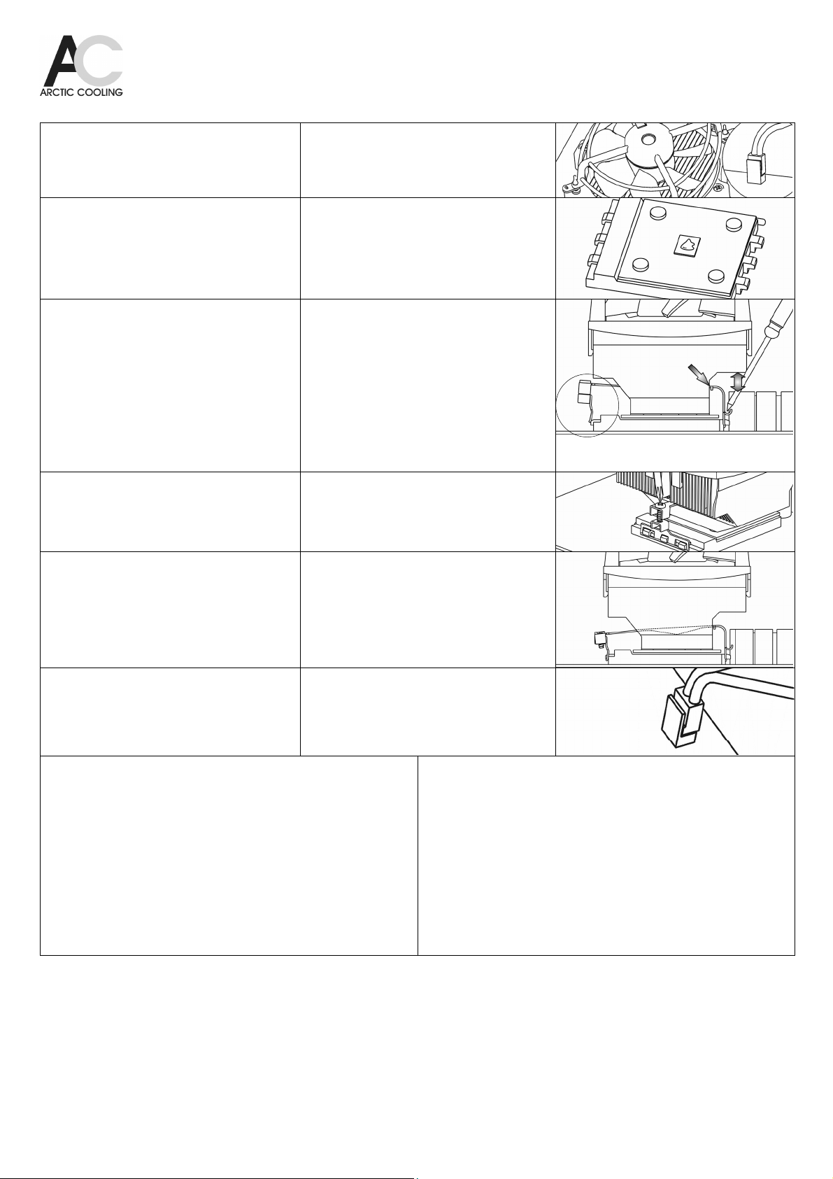
TSchritt 1:
Entfernen sie den Kühler samt Stromstecker
vorsichtig. Sollte der Stromstecker hartnäckig
klemmen, hilft eine Spitzzange. Klebt der Kühler auf
der CPU, rotieren sie diesen leicht.
Schritt 2:
Die CPU muss gereinigt werden. Pastenrückstände
sind mit einem Taschentuch vorsichtig zu entfernen.
Tragen sie die Paste auf die Mitte der sauberen
CPU auf. Verwenden sie ca. 1/4 der Spritze. Die
Paste nicht verstreichen.
Schritt 3:
Stellen sie sicher, dass die höhere
Kühleraussparung zur Clipseite mit dem
unbeweglichen Anschluss ausgerichtet ist und
schieben dieses so nahe an den Kühlkörper wie
möglich. Versichern sie, dass die Clipseite mit dem
beweglichen Anschluss so ausgerichtet ist wie auf
dem Bild gezeigt.
Dann setzen sie den Kühler auf die CPU auf, die
hohe Aussparung wie auf dem Bild gezeigt zu den
hohen Mainboardkomponenten ausgerichtet.
Hängen sie den unbeweglichen Anschluss mit Hilfe
eines Schraubendrehers bei den Sockelhaken ein.
Schritt 4:
Auf der gegenüberliegenden Seite des Sockels
hängen Sie den beweglichen Teil des Clips bei den
Haken ein und ziehen danach die Schraube mit
einem Kreuzschraubendreher so weit wie möglich
fest (Nr.2).
Schritt 5:
Stellen sie sicher, dass die Clip Laschen auf beiden
Seiten sauber in die Haken des Sockels eingehängt
sind und der Kühlkörper sich nicht lösen kann.
Step 1:
Remove both the existing cooler and plug carefully.
In some cases pliers may help to remove the plug.
If the cooler sticks to the CPU, rotate it slightly.
Step 2:
The CPU surface must be cleaned. Paste residue
is to be removed with a paper tissue cautiously.
Apply the thermal paste to the middle of the clean
CPU. About 1/4 of the injection will be used. Do not
spread the paste.
Step 3:
Make sure the side of the heat sink with the higher
cut out aligns with the fixed side of the clip and
move this end as close to the heatsink as possible.
Also assure that the flexible clip end is aligned as
shown in the picture.
Then place the cooler onto the CPU, with the high
cut out above the tall components of main board as
shown in the picture.
Install the lugs of the fixed side of clip to the socket
hooks with help of a screw driver.
Step 4:
On the opposite side of the socket, fix the fastening
side of the clip onto the hooks with a Philips screw
driver (No.2). Screw down the clip until it is
secured.
Step 5:
Confirm the lugs of the clip are properly installed to
the hooks of the socket on both side, and that the
heat sink cannot release anymore.
Schritt 6:
Installieren sie den Stromstecker auf dem
entsprechenden Anschluss des Mainboards.
Halten sie alle Kabel im Innern des Computers
durch Fixierung mit Kabelbindern fern vom Kühler.
Step 6:
Attach the power plug onto the according power
socket on the mainboard.
Keep all cables inside the computer case clear from
the fan by fixing them with cable ties.
TFAQ: Der Computer zeigt eine Ventilatorwarnung an oder schaltet nach wenigen
Sekunden aus
Das BIOS einiger Boardhersteller vergleicht die Drehzahl des Lüfters mit einem
Referenzwert. Wird dieser nicht erreicht, erfolgt entweder eine Warnung oder der PC
schaltet gleich wieder aus. Im Gegensatz zur Kontrolle der Temperatur ist die der
Drehzahl zwecklos, da je nach Lüfter die Solldrehzahl stark variiert. Diese Prüfung kann
im Bios deaktiviert werden. Nähere Angaben zu den Einstellungen fordern sie bitte beim
Boardhersteller an.
Stattdessen aktivieren sie die Temperaturwarnung. Diese schützt ihre
CPU auch im Falle von anderen Kühlproblemen als dem Defekt des Ventilators.
Im Falle, dass der PC den Bootvorgang gar nicht erst beginnt bzw. gleich wieder
ausschaltet, schliessen sie den Ventilator des Kühlers an einem anderen Stromstecker
des Mainboards an und installieren beim Stecker 1 einen Ventilator mit höherer Drehzahl.
So kann der Computer gestartet und im Bios die Drehzahlkontrolle ausgeschaltet werden.
Der CPU-Kühler muss bei dieser Prozedur nicht vom Prozessor entfernt werden.
FAQ: The Computer displays a fan warning or switches off after a few seconds
The BIOS of some mainboard manufacturers compares the speed of the fan with a
specified value. If the fan speed does not match the specified value, either the PC emits a
warning or switches off. Contrary to the temperature control, the RPM control is of no
importance, since fan speeds will be between 500 and 7000 RPM depending on the type
of fan. This RPM control can be deactivated in the BIOS settings. Please consult your
mainboard manufacturer for more information regarding these settings.
Instead activate the temperature warning. This protects your CPU also from other cooling
problems than a failing fan.
In the case of the PC is not booting or immediately switching off, attach the plug of the
cooler to the auxiliary power of the mainboard and attach a second fan with higher RPM
to the primary power socket. Now the PC can boot allowing the RPM control to be
deactivated in the BIOS settings. We recommend using a temperature control instead of a
RPM control. The cooler does not need to be removed from the processor for this
procedure.
 Loading...