

Arctic Cat 4000 2021 Service Manual

2021
4000
SERVICE
MANUAL
P/N-2263-107


Table of Contents
General Information/Foreword ............................................... 2
Snowmobile Identification ........................................................2
Recommended Gasoline and Oil .............................................2
Engine Break-In ....................................................................... 3
Drive Belt Break-In ................................................................... 3
Genuine Parts .......................................................................... 3
Varying Altitude Operation........................................................ 3
Preparation for Storage............................................................4
Preparation after Storage.........................................................4
After Break-In Checkup/Checklist ............................................ 5
Engine Specifications...............................................................5
Crankshaft Runout/Repair Specifications ................................5
Electrical Specifications ...........................................................6
Drive System Specifications..................................................... 6
Drive Clutch/Driven Clutch-Related Specifications ..................6
Drive System Components ......................................................6
Track Specifications ................................................................. 6
Torque Conversions ................................................................. 7
Torque Specifications ............................................................... 7
Steering and Body ................................................................... 9
Steering Post............................................................................ 9
Ski ..........................................................................................10
Ski Wear Bar .......................................................................... 11
Spindle ................................................................................... 11
Tie Rod................................................................................... 12
Ski Alignment ......................................................................... 13
A-Arms ...................................................................................14
Ski Shock Absorber................................................................ 15
Seat Assembly ....................................................................... 16
Taillight/Brake Light Assembly................................................ 16
Rear Bumper/Snowflap .......................................................... 16
Windshield/Headlight ............................................................. 17
Headlight Bulb........................................................................ 17
Adjusting Headlight Aim ........................................................ 17
Engine..................................................................................... 18
Engine Removing/Installing.................................................... 18
Assembly Schematic..............................................................25
Engine Servicing .................................................................... 27
Troubleshooting Engine ......................................................... 37
Engine-Related Items ................................................................ 39
Pressure Testing Engine ........................................................39
Liquid Cooling System ........................................................... 39
Cooling System Schematic .................................................... 40
Recoil Starter .........................................................................40
Arctic Power Valve (APV) System..........................................41
Troubleshooting Arctic Power Valve (APV) System ............... 46
Exhaust Controlled Timing (ECT) System.............................. 46
Fuel Systems ......................................................................... 47
EFI System............................................................................. 47
Individual Components........................................................... 47
Self-Diagnostic System/Codes............................................... 49
Fuel Pressure Regulator ........................................................ 50
Throttle Body Assembly .........................................................50
Throttle Cable......................................................................... 51
Fuel Pump..............................................................................52
Troubleshooting Fuel Systems............................................... 54
Electric Oil Pump.................................................................... 54
Gas Tank ................................................................................ 55
Electrical Systems .................................................................56
Ignition System ...................................................................... 56
Throttle Position Sensor ........................................................ 56
Electrical Resistance Tests.................................................... 57
Testing Electric Oil Pump....................................................... 58
Testing Voltage Regulator...................................................... 58
Testing Oil Level Sensor........................................................ 59
Testing Fuel Gauge Sender ................................................... 59
Emergency Stop Switch ........................................................ 59
Starter Relay Solenoid........................................................... 59
Fuse....................................................................................... 60
Ignition Switch ....................................................................... 60
Starter Motor.......................................................................... 60
Troubleshooting Electric Start................................................ 62
Brake Light Switch................................................................. 63
Testing Headlight Switch ....................................................... 63
Testing Handlebar Warmer Elements ................................... 63
Testing Thumb Warmer Element ........................................... 64
Testing Handlebar Warmer/Thumb Warmer Switch............... 64
Testing Tether ........................................................................ 64
Testing Speedometer Sensor ................................................ 64
Testing Shift Switch ............................................................... 65
Drivetrain/Track/Brake Systems ...........................................66
Drive Belt ............................................................................... 66
Drive Clutch ........................................................................... 66
Driven Clutch ......................................................................... 68
Drive Clutch/Driven Clutch .................................................... 70
Drivetrain ............................................................................... 70
Drive Sprockets ..................................................................... 73
Track Tension ........................................................................ 74
Track Alignment..................................................................... 75
Brake System ........................................................................ 76
Brake Lever/Master Cylinder Assembly................................. 80
Troubleshooting Hydraulic Brake System.............................. 81
Troubleshooting Track ........................................................... 82
Troubleshooting Drive Clutch/Driven Clutch.......................... 83
Suspension .............................................................................84
Chassis and Skid Frame Mounting Locations ....................... 85
Servicing Suspension ............................................................ 87
1

General
Information/Foreword
NOTE: General specifications for each 2021 Arctic
Cat Snowmobile can be accessed from the Arctic Cat
Cat Tracker Dealer Communication System.
NOTE: Some illustrations and photographs used in
this section are used for clarity purposes only and are
not designed to depict actual conditions.
This Service Manual contains service and maintenance
information for 2021 Arctic Cat 4000 snowmobile models. The manual is designed to aid service personnel in
service-oriented applications.
This manual is divided into sections that cover specific
snowmobile components or systems and, in addition to
the standard service procedures, include assembling, disassembling, and inspecting instructions. When using this
manual as a guide, the technician should use discretion as
to how much disassembly is needed to correct any given
condition.
The service technician should become familiar with the
operation and construction of the components or systems
by carefully studying the complete manual. This will
assist the service technician in becoming more aware of
and efficient with servicing procedures. Such efficiency
not only helps build consumer confidence but also saves
time and labor.
All Arctic Cat publications and snowmobile decals display the words Warning, Caution, and Note to emphasize
important information. The symbol ! WARNING
identifies personal safety-related information. Be sure to
follow the directive because it deals with the possibility
of severe personal injury or even death. A CAUTION
identifies unsafe practices which may result in snowmobile-related damage. Follow the directive because it deals
with the possibility of damaging part or parts of the
snowmobile. The symbol NOTE: identifies supplementary information worthy of particular attention.
At the time of publication, all information, photographs,
and illustrations were technically correct. Some photographs and illustrations used in this manual are used for
clarity purposes only and are not designed to depict actual
conditions. Because Arctic Cat Inc. constantly refines and
improves its products, no retroactive obligation is incurred.
Snowmobile Identification
The Arctic Cat Snowmobile has two important identification numbers. The Vehicle Identification Number (VIN)
is stamped into the tunnel near the right-side footrest.
The decal also displays pertinent production information.
The Engine Serial Number (ESN) is stamped into the
crankcase of the engine.
These numbers are required to complete warranty claims properly. No warranty will be allowed by Arctic Cat if the engine
serial number or VIN is removed or mutilated in any way.
Recommended Gasoline
and Oil
CAUTION
Do not use white gas or gasoline containing methanol.
Only Arctic Cat-approved gasoline additives should be
used.
RECOMMENDED GASOLINE
The recommended gasoline to use is 91 octane (minimum).
NOTE: If a situation arises in which 91 octane gaso-
line is not available, 87 octane gasoline can be substituted; however, do not prolong the usage of 87 octane
gasoline as it will cause poor engine performance.
In many areas, oxygenates are added to the gasoline.
Oxygenated gasolines containing up to 10% ethanol are
acceptable gasolines.
RECOMMENDED OIL
CAUTION
Any oil used in place of the recommended oil may
cause serious damage.
The recommended oil to use in the oil-injection system is
Arctic Cat C-TEC2 Synthetic 2-Cycle Oil (p/n 8639-118 —
quart), (p/n 7639-840 — gal.), or (p/n 6639-521 — 2.5
gal.) This oil is specially formulated to be used and meets
all of the lubrication requirements of the Arctic Cat
C-TEC2 snowmobile engine.
All materials and specifications are subject to change
without notice.
Product Service and Warranty Department
Arctic Cat Inc.
2

Engine Break-In
The Arctic Cat engine (when new) requires a short
break-in period before the engine is subjected to heavy
load conditions.
The break-in period occurs in two stages. Stage One
occurs during the first 18 minutes of a new engine’s run
time where the ECM provides additional oil to the
engine, along with limiting engine RPM to 6500 RPM.
Stage Two occurs after the completion of Stage One and
eliminates the engine RPM limiter. However, Stage Two
still provides additional oil to the engine for the remainder of 6 hours. This additional oil is less than the amount
added during Stage One.
Premixing fuel and oil during the break-in period is not
required. Due to the oil delivery control strategy of the
electronic oil pump, the oil pump will automatically
compensate and deliver a richer fuel-oil ratio during the
engine break-in period.
Drive Belt Break-In
CLUTCHING
On a normally-aspirated engine as altitude changes,
engine horsepower changes with it. As you go up in altitude, the engine loses horsepower. Because of this, the
continuously variable transmission (CVT) system needs
to be calibrated to compensate for the horsepower loss.
At altitudes above 5000 ft (1524 m), the engine loses
peak horsepower but will also lose horsepower at
engagement speed. For this reason, calibrating the drive
system is usually needed in order to attain acceptable performance. Changing drive clutch engagement speed can
be done several ways. Some of the methods will affect
other characteristics of CVT operation, so you must be
careful what you change. Drive clutch springs are the
most common way to increase engagement speed; however, by simply changing the cam arms to a lighter
weight from the heavier sea level cam arm, you will gain
some engagement speed.
The driven clutch will also play a part in CVT tuning for
high altitude operation. A steeper helix (torque bracket)
angle in the driven clutch will mean a quicker up-shift. A
shallower angle will mean a slower up-shift. If the
up-shift is too quick, due to a very steep helix, RPM will
be pulled down under the peak operating RPM of the
engine (where the horsepower is) and performance will
suffer. The engine may even bog.
Drive belts require a break-in period of 25 miles (40 km).
Drive the snowmobile for 25 miles (40 km) at 3/4 throttle
or less. By revving the engine up and down (but not
exceeding 60 mph [97 km/h]), the exposed cord on the
side of a new belt will be worn down. This will allow the
drive belt to gain its optimum flexibility and will extend
drive belt life.
NOTE: Before starting the snowmobile in extremely
cold temperatures, the drive belt should be removed
and warmed up to room temperature. Once the drive
belt is at room temperature, install the drive belt (see
Drive Belt sub-section in the Drivetrain/Track/Brake
Systems section of this manual).
CAUTION
Running the engine with the drive belt removed could
result in serious engine damage and drive clutch failure.
Genuine Parts
When replacement of parts is necessary, use only genuine
Arctic Cat parts. They are precision-made to ensure high
quality and correct fit.
Varying Altitude Operation
Operating a snowmobile at varying altitudes requires
recalibration of drive system components. Consult the
appropriate specification sheet on Cat Tracker Online.
ENGINE
A normally aspirated engine will generate more horsepower at sea level than it does at higher altitudes. The
reason is that the higher you go, less oxygen is available
for the engine to use during its combustion process. Less
oxygen means it needs less fuel to obtain the correct
air/fuel ratio to operate properly. This is why the fuel
ratio has to be recalibrated. High altitude engines operate
as though they have a lower compression ratio. This,
along with less oxygen and less fuel, means that the
engine generates less horsepower. All of these characteristics will become more evident the higher the altitude.
TRACK
Carefully matching the riding requirements to the type of
track will ensure the maximum use of all available engine
power. Lug height and track durometer are the two main
concerns when selecting a track for various riding styles.
Tracks exist with lug heights from 1.0” up to 2.0” to
accommodate various snow conditions. Generally, the
deeper the snow, the taller the lug. It must be noted that
the installation of any deep-lug track may reduce top end
speed and promote premature wear strip wear in marginal
snow conditions.
Durometer is a measurement of how hard a rubber is. The
lugs on most tracks range between 60 and 80 durometer.
On the durometer scale, the higher the number, the harder
the lugs. For riding in deep powder snow, a softer durometer track works best. The softer rubber allows the track
to “give” a little and pack the snow creating lift rather
than digging its way straight down. When hill-climbing,
the harder lug of an 80 durometer track works the best
due to penetrating the hard snow creating more bite.
Following are basic altitude theories for clutching,
engine, suspension, and track.
3

Preparation for Storage
Prior to storing the snowmobile, it must be properly serviced to prevent corrosion and component deterioration.
11. Clean and polish the hood, console, and chassis with
Cat Cleaner. DO NOT USE SOLVENTS. THE PROPELLENT WILL DAMAGE THE FINISH.
12. Disconnect the battery cables making sure to disconnect the negative cable first; then clean the battery
posts and cables.
1. Clean the seat cushion with a damp cloth and Arctic
Cat Vinyl Protectant.
2. Clean the snowmobile thoroughly by hosing dirt, oil,
grass, and other foreign matter from the skid frame,
tunnel, hood, and belly pan. Allow the snowmobile
to dry thoroughly. DO NOT get water into any part
of the engine.
3. Place the rear of the snowmobile up on a shielded
safety stand; then start the engine and allow to idle.
Spray an Engine Storage Preserver into the intake
until the engine exhaust starts to smoke heavily or
until the engine starts to drop in RPM. Turn engine
off.
CAUTION
Do not run the engine without the belt guard in place
and secured.
4. Plug the exhaust system outlet with steel wool.
5. With the ignition switch in the OFF position:
A. Disconnect the high tension lead from the spark
plug; then remove the plug, connect it to the
lead, and ground on the cylinder head.
CAUTION
Never crank the engine over without grounding the
spark plug. Damage to coil and/or ECM may result.
CAUTION
Sealed batteries require charging if left for extended
non-start periods. Arctic Cat recommends trickle
charging once a month. Follow the manufacturer’s
instructions and cautions.
13. If possible, store the snowmobile indoors. Raise the
track off the floor by blocking up the back end making sure the snowmobile is secure. Loosen the track
adjusting bolts to reduce track tension. Cover the
snowmobile with a machine cover or a heavy, ventilated tarpaulin to protect it from dirt and dust.
14. If the snowmobile must be stored outdoors, position
the snowmobile out of direct sunlight; then block the
entire snowmobile off the ground making sure the
snowmobile is secure. Loosen the track adjusting
bolts to reduce track tension. Cover with a machine
cover or a heavy, ventilated tarpaulin to protect it
from dirt, dust, and rain.
CAUTION
Avoid storing in direct sunlight and using a plastic
cover as moisture may collect on the snowmobile causing corrosion.
Preparation after Storage
B. Pour 29.5 mL (1 fl oz) of SAE 30 petro-
leum-based oil into the spark plug hole and pull
the recoil starter handle slowly about 10 times.
C. Install the spark plug and connect the high ten-
sion lead.
6. Fill the gas tank to its rated capacity; then add Arctic
Cat Fuel Stabilizer to the gas tank following directions on the container for the stabilizer/gasoline
ratio. Tighten the gas tank cap securely.
7. With the snowmobile level, check the lubricant level
in the chain case. If low, add chain lube through the
fill plug hole.
8. Remove the drive belt from the drive clutch/driven
clutch. Lay the belt on a flat surface or slide it into a
cardboard sleeve to prevent warping or distortion
during storage; then clean and inspect the drive
clutch and driven clutch.
9. Apply light oil to the upper steering post bushings and
to the shafts of the shock absorbers; then lubricate the
rear suspension with low-temperature grease.
10. Tighten all nuts, bolts, and cap screws making sure all
calibrated nuts, bolts, and cap screws are tightened to
specifications. Make sure all rivets holding the components together are tight. Replace all loose rivets.
Taking the snowmobile out of storage and correctly preparing it for another season will ensure many hours of
trouble-free snowmobiling. Arctic Cat recommends the
following procedure:
1. Clean the snowmobile thoroughly. Polish the exterior
of the snowmobile.
2. Clean the engine. Remove the cloth from the exhaust
system. Check exhaust system and air silencer for
obstructions.
3. Inspect all control wires and cables for signs of wear
or fraying. Replace if necessary. Use cable ties or
tape to route wires and cables away from hot or rotating parts.
4. Inspect the drive belt for cracks and tears. Check belt
specifications. Replace if damaged or worn. Install
the drive belt.
NOTE: If the old belt is worn but in reasonable con-
dition, retain it with the snowmobile as a spare in case
of emergency.
5. Adjust the throttle cable. Inspect all fuel hoses and
oil hoses for deterioration or cracks; replace if necessary. Make sure all connections are tight.
6. Fill the oil-injection reservoir with the recommended
2-cycle oil; then inspect the spark plug. Replace,
gap, or clean as necessary.
4
7. Tighten all nuts, bolts, and cap screws making sure
all calibrated nuts, bolts, and cap screws are tightened to specifications.
8. If not done during preparation for storage, lubricate
the rear suspension with low-temperature grease.
R Check skid frame and A-arm mounting hardware
for tightness
R Check brake lever travel and adjustment
R Grease all lubrication points
9. Check the coolant level and all coolant hoses and
connections for deterioration or cracks. Add properly
mixed coolant as necessary.
10. Charge the battery; then connect the battery cables
making sure to connect the positive cable first. Test
the electric start system.
11. Inspect the entire brake system, all controls, headlight, taillight, brake light, ski wear bars, and headlight aim; adjust or replace as necessary.
12. Adjust the track to the proper tension and alignment.
After Break-In
Checkup/Checklist
Certain areas require adjustment after the break-in period
in order to obtain peak performance. These areas are the
following:
DRIVE CLUTCH/DRIVEN CLUTCH
ALIGNMENT (OFFSET) — The alignment between
the drive clutch and driven clutch are set at the factory.
Normally, no adjustment is necessary; however, if premature drive belt wear or poor performance is experienced,
the drive clutch/driven clutch alignment must be
checked. See “CHECKING OFFSET” in the Drivetrain
section in this manual.
TRACK TENSION AND ALIGNMENT — A certain
amount of stretch occurs on all tracks during the first 500
miles (800 km). The track must be inspected/adjusted
after the first 50 to 100 miles (80 to 160 km) to the specifications given in the Track Specifications sub-section of
this section and periodically thereafter. If these adjustments aren’t performed, the track may “derail” which
leads to track and slide rail damage.
Along with these major areas, other areas should be
checked and adjusted.
Engine Specifications
ITEM
Engine Number 0962-153
Displacement 397 cc
Bore x Stroke 85 x 70
Compression Ratio 6.60:1
Cooling System Liquid
Ignition Timing (Engine Warm) 19° @ 1750 RPM
Spark Plug (NGK) BPR9ES
Spark Plug Gap 0.028-0.031 in.
Piston Skirt/Cylinder Clearance 0.0041-0.0053 in.
Piston Ring End Gap 0.012-0.0196 in.
Cylinder Trueness Limit 0.004 in.
Piston Pin Diameter 0.8659-0.8661 in.
Piston Pin Bore Diameter 0.8661-0.8665 in.
Connecting Rod Small End Bore 1.0631-1.0634 in.
Connecting Rod Radial Play 0.0001-0.0008 in.
Crankshaft Runout (t.i.r.) 0.002 in. (0,0508 mm)
Crankshaft End Play 0.008 in. (0,2032 mm)
(0.7112-0.7874 mm)
(0.1041-0.1346 mm)
(0.3048-0.49784 mm)
(0,1016 mm)
(21,993-21,998 mm)
(21,998-22-009 mm)
(27.002-27.010 mm)
(0,0025-0,0203 mm)
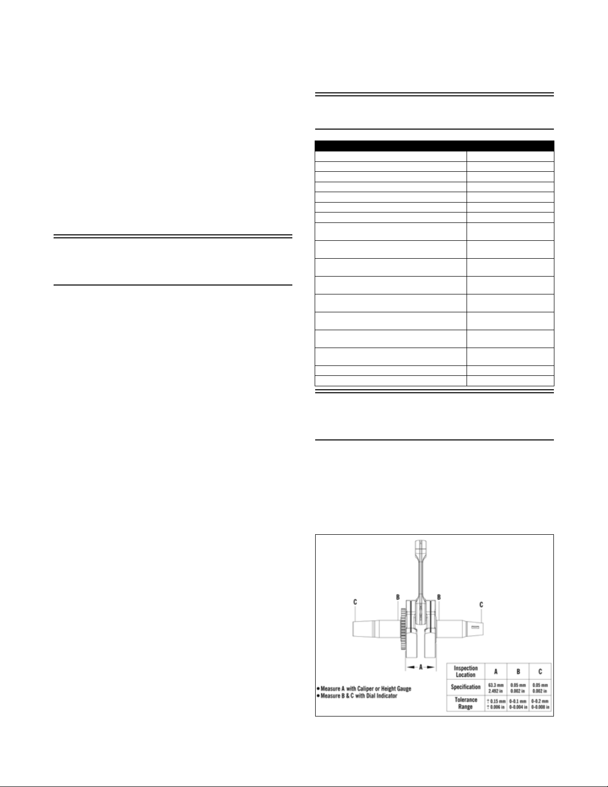
Crankshaft Runout/Repair
Specifications
Refer to the drawing; then find the letter indicating the
specification and refer to the chart within the illustration.
NOTE: From the illustration, note that four check
points are called out: at either end, out on the taper as
shown. The crankshaft is still supported on the outer
shafts using V blocks.
Below is a list of items to check after the break-in period.
The recommended mileage for this inspection is between
100 and 300 miles (160 and 480 km).
R Check drive clutch/driven clutch alignment
R Adjust track tension and alignment
R Check throttle cable tension
R Check engine idle
R Check coolant level
R Check chain case lubricant level
R Check lights (high/low beam, brake light)
R Check safety switch operation
R Check engine compartment for any rubbing com-
ponents
R Check steering hardware for tightness
0755-040
5

Electrical Specifications
(Normally Open Ignition)
Component Test Value + Test Connections -
Spark Plug Cap 4000-6000 ohms cap end cap end
Oil Level Sensor Less than 1 ohm (float end down) terminal terminal
Ignition Switch Less than 1 ohm (key in OFF position) terminal terminal
Ignition Coil (Primary)
Charge Coil (1) 8.8-13.2 ohms black/red green/red
Charge Coil (2) 8.8-13.2 ohms brown/white green/red
Lighting Coil 0.08-0.12 ohm yellow yellow
Ignition Timing Sensor (1) 148-222 ohms green/white brown/green
Ignition Timing Sensor (2) 148-222 ohms green/white brown/green
Fuel Injector 11.4-12.6 ohms terminal terminal
Injection Coil 15.2-22.8 ohms blue/white blue/white
Fuel Pump Coil 1.52-2.28 ohms orange orange
Servomotor 12 DC Volts red/brown (counterclockwise)
Voltage Regulator/Rectifier* 9-15 DC Volts red/blue black
(Secondary)
* Harness plugged in
NOTE: Lighting coil output is unregulated voltage.
Most voltages generated by the ignition system are sufficient to interrupt pacemakers! All technicians, especially
those using pacemakers, must avoid contact with all electrical connections when pulling the recoil starter rope or
after the engine has been started.
0.24-0.36 ohm
5040-7560 ohms
! WARNING
black/white
high tension wire
brown/red (clockwise)
white/blue
ground
brown/red (counterclockwise)
red/brown (clockwise)
Drive System
Specifications
Model Altitude
Blast ZR 0-3000 ft
Blast LT 0-3000 ft
Blast M 0-3000 ft
(0-915 m)
(0-915 m)
(0-915 m)
Drive Clutch
Spring
700-1115N 11.5 700-1000N 0823-683 3200 ± 100 7500 19T 50T 90
700-1115N 11.5 700-1000N 0823-683 3200 ± 100 7500 19T 50T 90
700-1115N 11.5 700-1000N 0823-683 3200 ± 100 7500 19T 50T 90
Mass
Block
Driven Clutch
Drive Clutch/Driven
Clutch-Related
Specifications
ALIGNMENT BAR
Offset P/N Center-to-Center Offset
0644-654 11.50” 1.39”
Drive System Components
Spring
Drive Belt
Engagement
RPM
Peak
RPM
Top
Gear
Bottom
Gear
Chain
Pitch
Track Specifications
Model Length Lug Height
Blast ZR 121” (3073 mm) 1.0” (25 mm)
Blast LT 146” (3708 mm) 1.6” (41 mm)
Blast M 146” (3708 mm)
NOTE: The track tension on all models should be
20 lb @ 2 inches (9 kg @ 50 mm).
2.0” (50 mm)
A list of drive system components that are available
through the Arctic Cat Service Parts Department can be
found in the Quick Reference Guide. This information
will be useful when doing any fine-tuning on the drive
system.
6

Torque Conversions Torque Specifications
ft-lb N-m ft-lb N-m ft-lb N-m ft-lb N-m
1 1.4 26 35.4 51 69.4 76 103.4
2 2.7 27 36.7 52 70.7 77 104.7
3 4.1 28 38.1 53 72.1 78 106.1
4 5.4 29 39.4 54 73.4 79 107.4
5 6.8 30 40.8 55 74.8 80 108.8
6 8.2 31 42.2 56 76.2 81 110.2
7 9.5 32 43.5 57 77.5 82 111.5
8 10.9 33 44.9 58 78.9 83 112.9
9 12.2 34 46.2 59 80.2 84 114.2
10 13.6 35 47.6 60 81.6 85 115.6
11 15 36 49 61 83 86 117
12 16.3 37 50.3 62 84.3 87 118.3
13 17.7 38 51.7 63 85.7 88 119.7
14 19 39 53 64 87 89 121
15 20.4 40 54.4 65 88.4 90 122.4
16 21.8 41 55.8 66 89.8 91 123.8
17 23.1 42 57.1 67 91.1 92 125.1
18 24.5 43 58.5 68 92.5 93 126.5
19 25.8 44 59.8 69 93.8 94 127.8
20 27.2 45 61.2 70 95.2 95 129.2
21 28.6 46 62.6 71 96.6 96 130.6
22 29.9 47 63.9 72 97.9 97 131.9
23 31.3 48 65.3 73 99.3 98 133.3
24 32.6 49 66.6 74 100.6 99 134.6
25 34 50 68 75 102 100 136
NOTE: Torque specifications have the following tol-
erances:
Tor que Tol eran ce
0-15 ft-lb (0-20 N-m) ±20%
16-39 ft-lb (21-53 N-m) ±15%
40+ ft-lb (54+ N-m) ±10%
Tor qu e
Item Secured to ft-lb N-m
DRIVE SYSTEM
Drive Clutch Engine 51 69.4
Drive Clutch Cover Stationary Sheave 130 176.3
Ring Gear/Damper Drive Clutch 22 29.9
Driven Clutch Driven Shaft 20 27.2
Chain Case (Cap Screw) Chassis 10 13.6
Chain Case (Torx-Head
Screw)
Chain Case Cover Chain Case 108 in.-lb 12.2
Brake Caliper Chassis 25 34
Outside Caliper Housing Inside Caliper
Brake Line Caliper 25 34
Brake Line Master Cylinder 25 34
Brake Caliper Shield Cover 96 in.-lb 10.8
STEERING/FRONT SUSPENSION/CHASSIS
Ski Spindle 35 47.6
Ski Wear Bar 15 20.4
Ski Ski Handle 54 in.-lb 6.1
Steering Support Mounting Block 108 in.-lb 12.2
Steering Post Chassis 20 27.2
Steering Post Cap Riser Block 20 27.2
Tie Rod Steering Post 20 27.2
Tie Rod Spindle Arm 32 43.5
Steering Support Spar 25 34
A-Arm (Upper) Chassis 108 in.-lb 12.2
A-Arm (Lower) Chassis (Front) 65 88.4
A-Arm (Lower) Chassis (Rear) 45 61.2
A-Arm (Upper) Spindle 20 27.2
A-Arm (Lower) Spindle 45 61.2
Shock Absorber A-Arm (Lower) 24 32.6
Shock Absorber Chassis 24 32.6
Wear Strip Rail 50 in.-lb 5.6
End Cap Rail 80 in.-lb 9.2
Idler Wheel/Idler Wheel
Block
Front Arm Rail 52 70.7
Front Arm Tunnel 41 55.8
Idler Arm Tunnel 45 61.2
Front Shock Rail 45 61.2
Front Shock Front Arm 40 54.4
Limiter Strap Limiter Strap 72 in.-lb 8.1
Idler Arm Rear Arm 24 32.6
Rear Wheel Axle Rail 35 47.6
Rear Arm Rail 45 61.2
Rear Shock/Rear Shock
Link
Rear Arm Stop Rail 20 27.2
Rear Shock Idler Arm 40 54.4
Spring Slide Rail 20 27.2
Shock Pivot Front Arm 45 61.2
Wear Strip Rail 50 in.-lb 5.6
End Cap Rail 80 in.-lb 9.2
Chassis 13 17.7
Housing
25 34
REAR SUSPENSION (ZR)
Rail 10 13.6
Shock Pivot 40 54.4
REAR SUSPENSION (LT)
7

Torque
Item Secured to ft-lb N-m
REAR SUSPENSION (LT) (cont.)
Idler Wheel/Idler Wheel
Block
Front Arm Rail 52 70.7
Front Arm Tunnel 41 55.8
Idler Arm Tunnel 45 61.2
Front Shock Rail 45 61.2
Front Shock Front Arm 40 54.4
Limiter Strap Limiter Strap 72 in.-lb 8.1
Idler Arm Rear Arm 24 32.6
Rear Wheel Axle Rail 35 47.6
Rear Arm Rail 45 61.2
Rear Shock/Rear Shock
Link
Rear Shock/Rear Shock
Link
Rear Arm Stop Rail 20 27.2
Spring Slide Rail 20 27.2
Swing Arm Rail 40 54.4
Rail 10 13.6
Front Arm 40 54.4
Idler Arm 40 54.4
REAR SUSPENSION (M)
Wear Strip Rail 50 in.-lb 5.6
Idler Wheel Rail/Shaft 13 17.7
Front Arm Rail 52 70.7
Front Shock Front Arm 24 32.6
Front Shock Rail 52 70.7
Rear Arm Rail 13 17.7
Rear Arm Idler Arm 24 32.6
Track Guide Rear Arm 24 in.-lb 2.7
Rear Axle Rail 24 32.6
Rear Shock Idler Arm 24 32.6
Rear Shock Rear Shock Pivot 24 32.6
Rear Shock Link Rear Shock Pivot 24 32.6
Rear Shock Link Idler Arm 24 32.6
Skid Frame Tunnel 45 61.2
Limiter Strap Limiter Strap 72 in.-lb 8.1
Limiter Strap Rail 15 20.4
8
Steering and Body
This section has been organized into sub-sections for servicing steering and body components; however, some
components may vary from model to model. The technician should use discretion and sound judgment when
removing and installing components.
NOTE: Whenever a part is worn excessively,
cracked, or damaged in any way, replacement is necessary.
SPECIAL TOOLS
A number of special tools must be available to the technician when servicing the steering and body systems.
Description p/n
Handlebar Stand 5639-152
Steering Post Stand 5639-946
NOTE: Special tools are available from the Arctic
Cat Service Parts Department.
Steering Post
SNO-763
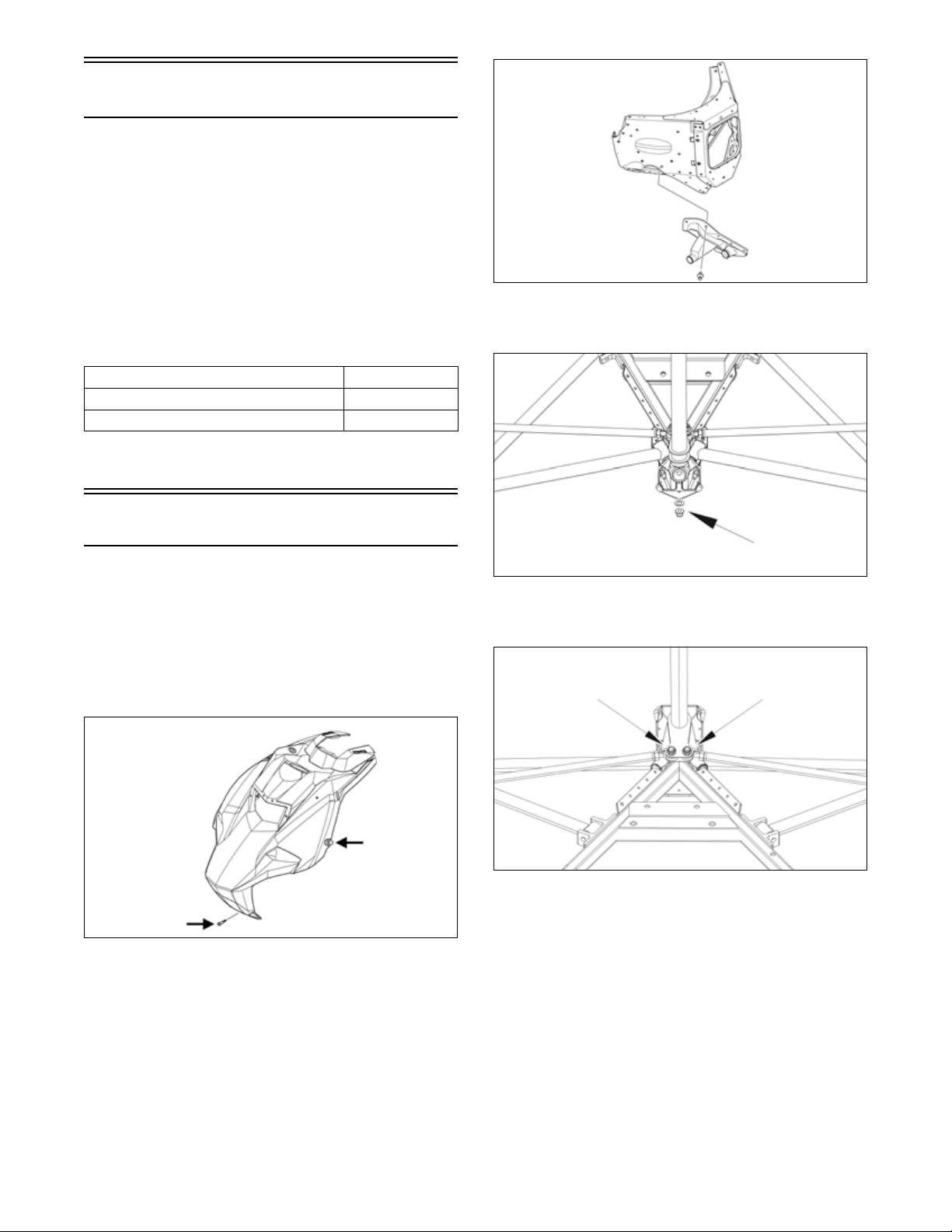
5. Remove the nut and washer securing the bottom of
the steering post to the chassis. Discard the nut.
REMOVING
1. Rotate the two quarter turns to the vertical position;
then pull the top of the side panel out and up and off
the skid plate.
2. Remove the Torx screw securing the front of the
hood to the chassis; then loosen the two quarter-turns
securing the hood.
ONS-305
3. Disconnect the hood harness and remove the hood;
then remove the screws securing the front belly pan
to the front frame.
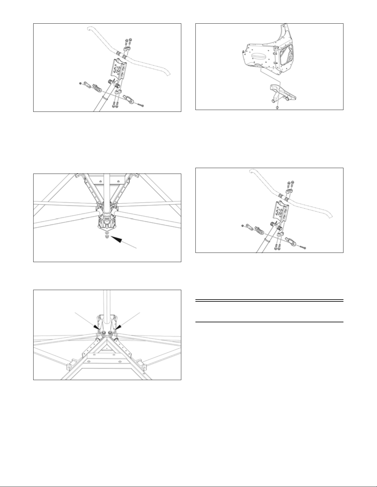
0755-041
6. Remove the two cap screws and nuts securing the tie
rod ends to the steering post. Discard both nuts.
0755-042
7. Remove the cap screws and handlebar caps securing
the handlebar to the top of the handlebar riser; then
remove the two nuts securing the top of steering post
to the chassis. Account for both steering post blocks
and retaining plate.
4. Remove the push rivets securing the right-side steering boot to the chassis. This allows access to the two
tie rod cap screws and nuts.
9
SNO-357
8. Carefully remove the steering post from the snowmobile.
INSTALLING
1. Install steering post into position in the chassis.
Secure the steering post using the existing washer
and a new nut. Tighten to 20 ft-lb (27.2 N-m).
0755-041
2. Secure the tie rod assemblies to the steering post
using two new nuts. Tighten to 20 ft-lb (27.2 N-m).
SNO-763
4. Secure the top of the steering post to the steering
support using the existing retaining plate and nuts.
Tighten to 96 in.-lb (10.8 N-m).
5. Install the handlebar riser and handlebar to the top of
the steering post and secure using the existing caps
and screws. Tighten evenly to 20 ft-lb (27.2 N-m).
SNO-357
6. Position the hood onto the snowmobile and connect
the hood harness connector. Secure using the existing screw and the two quarter-turns.
7. Install the access panels.
0755-042
3. Secure the steering boots to the chassis using the
existing push rivets.
10
Ski
REMOVING
1. Elevate the front of the snowmobile and secure on a
support stand.
2. Remove and discard the cotter pin; then remove the
nut and cap screw securing the ski to the spindle.
NOTE: Note the orientation of the damper for
installation purposes.
3. Remove the ski. Account for the rubber damper,
axle, spacers and washers.
INSPECTING
1. Inspect the ski for cracks or deterioration.
2. Inspect the ski for abnormal bends or cracks.
3. Inspect the wear bar for wear.
4. Inspect all hardware and the spindle bushings for
wear and damage.

5. Inspect the rubber damper for damage or wear.
INSTALLING
1. Slide a washer onto the cap screw used to secure the
ski; then apply low-temperature grease to the shaft
portion of the cap screw and spindle axle.
2. Install the spindle axle and spacers into the spindle;
then position the ski damper into the bottom of the
ski making sure the damper is properly positioned
for the desired ski stance.
0752-477
NOTE: The ski damper must be positioned in the
ski so it is directly under the spindle.
Spindle
0755-083
REMOVING
1. Position the front of the snowmobile on a safety
stand; then remove the ski.
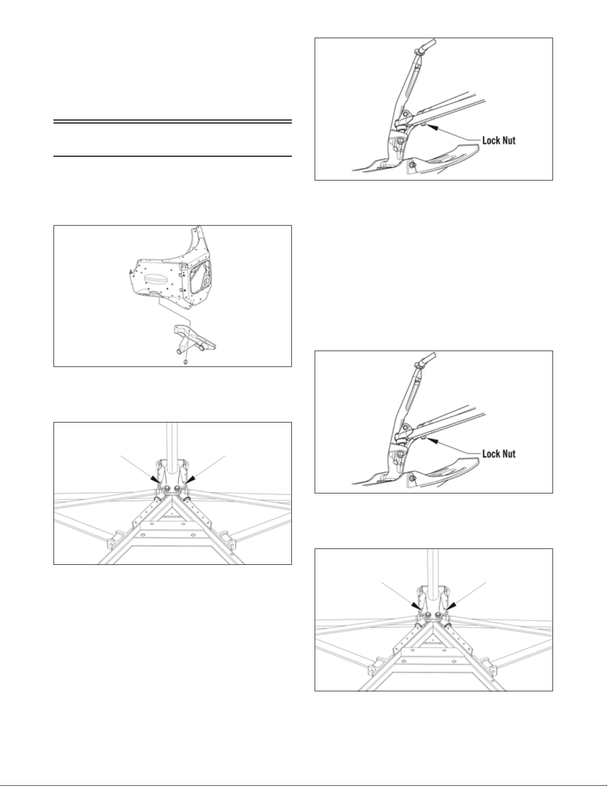
2. Remove the two cap screws and nuts securing the
shock to the chassis and to the lower A-arm.
3. Remove the lock nut securing the tie rod to the spindle arm. Account for the washer on the top side.
3. With the cap screw hole of the ski centered with the
spindle axle, slide the cap screw with washer through
the outside of the ski and spindle assemblies.
NOTE: Install the cap screw so the lock nut will be
located to the inside of the ski and the cotter pin slot
in the cap screw will be horizontal with the ski.
4. Install the remaining washer and lock nut; then
tighten the lock nut to 35 ft-lb (47.6 N-m).
5. Install a new cotter pin from the back side of the ski
cap screw and spread the pin.
Ski Wear Bar
The ski wear bar is a replaceable bar attached to the
underside of the ski. If the snowmobile is operated primarily in deep snow, ski wear bar wear will be minimal;
however, if the snowmobile is operated on terrain where
the snow cover is minimal, the ski wear bar will wear
faster. Arctic Cat recommends that the ski wear bars be
replaced if worn to 1/2 of original diameter.
REMOVING
1. Raise the front of the snowmobile and secure with a
suitable stand.
2. Remove the lock nuts securing the wear bar to the
ski; then remove the wear bar.
INSTALLING
1. Install the wear bar into the ski making sure it is fully
seated using a rubber mallet.
2. Secure the wear bar with lock nuts. Tighten to 15
ft-lb (20.4 N-m).
4. Remove the machine screw and tri-nut securing the
upper A-arm ball joint to the spindle.
5. Remove the lock nut securing the spindle to the
lower A-arm; then using a rubber mallet, remove the
lower arm from the spindle.
INSPECTING
1. Inspect the spindle for excessive wear, cracks, bends,
or imperfections.
2. Inspect the A-arm bushings and axle area for wear.
3. Inspect the ski spindle axle and bearings for wear,
damage, or loose fit. Replace the bearings as a set.
NOTE: Replacing the ski bushings is difficult. The
existing bushings will be damaged during removal. Be
careful, however, not to damage the spindle when removing the bushings. Press the new bushings into the spindle.
INSTALLING
1. Install the lower A-arm into the spindle and loosely
secure using a new lock nut.
2. Loosely secure the upper A-arm ball joint to the
spindle using the existing machine screw and the
tri-nut. Raise the spindle so the upper A-arm is level;
then tighten the new screw securing the ball joint to
the spindle to 20 ft-lb (27.2 N-m).
3. Install the shock and secure using the existing cap
screws and new lock nuts. Tighten to 24 ft-lb (32,6
N-m).
4. Remove the snowmobile from the support stand.
Tighten lower A-arm lock nut to 45 ft-lb (61,2 N-m).
NOTE: The weight of the snowmobile will allow the
lower ball joint to seat into the spindle before tightening the nut.
11
5. Place the tie rod with washer into position on the
spindle arm. Secure with a new lock nut. Tighten to
32 ft-lb (43,5 N-m).
6. Install the ski.
7. Turn the handlebar fully to the right and then to the
left to verify the steering moves freely.
Tie Rod
REMOVING
1. Remove the push rivets securing the right-side steering boot to the chassis. This allows access to the two
tie rod cap screws and nuts.
SNO-763
2. Remove both machine screws and nyloc nuts securing the steering tie rod ends to the steering arm. Discard both nuts.
0755-084
4. Slide the steering tie rod out of the steering boot and
out of the snowmobile.
INSPECTING
1. Inspect the ball joints for damaged threads or wear.
2. Inspect the tie rod for damage, unusual bends, or
wear.
INSTALLING
1. Slide the steering tie rod through the steering boot
and into the snowmobile; then place the steering tie
rod into the spindle arm with the washer. Secure
with a new nyloc nut. Tighten to 32 ft-lb (43,5 N-m).
0755-042
3. Remove the nyloc nuts securing the tie rod ends to
the spindle arms. Account for the washers.
12
0755-084
2. Secure the tie rod to the steering tie rod bracket with
the screw and new nyloc nut. Tighten to 20 ft-lb
(27.2 N-m).
0755-042
Ski Alignment
CHECKING
NOTE: Track tension and alignment must be properly adjusted prior to checking or adjusting ski alignment. Ski alignment must be performed on a flat,
level surface. Ski toe-out must fall within the range of
1/16-1/4 in (1.6-6.4 mm).
1. Raise the front end of snowmobile just high enough
to keep the skis from contacting the floor.
2. Turn the handlebar to the straight-ahead position.
Visually inspect the handlebar for being centered and
in the straight-ahead position.
3. With the handlebar in the straight-ahead position,
secure the handlebar to prevent the alignment from
becoming disturbed during the remainder of the
alignment procedure.
NOTE: Track tension and alignment must be prop-
erly adjusted prior to placing the straightedge against
the outside edge of the track.
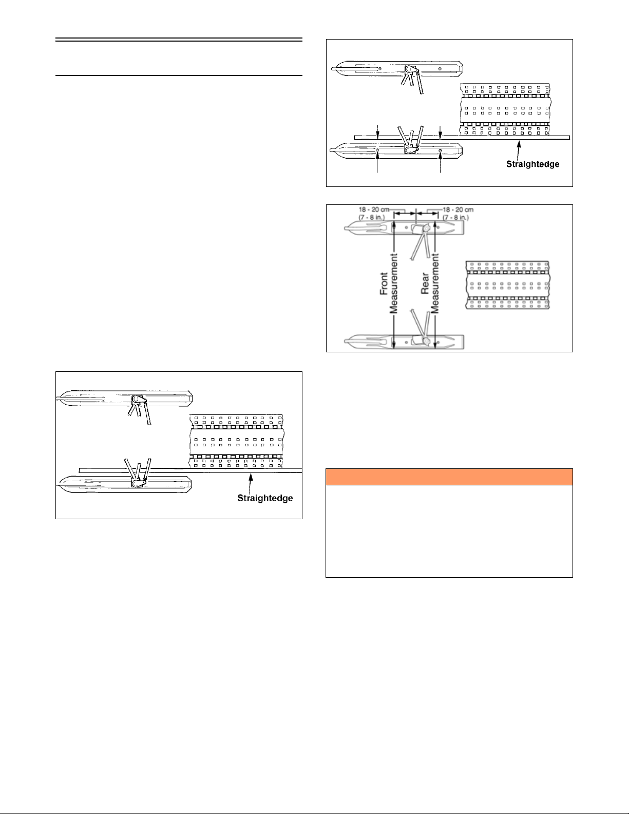
4. Place a long straightedge against the outside edge of
the track so it lies near the inside edge of the left-side
ski.
729-887A
0734-408
6. Place the straightedge against the outside edge of the
track so it lies near the inside edge of the right-side
ski.
729-887B
NOTE: The straightedge should be long enough to
extend from the back of the track to the front of the
ski.
5. Measure the distance from the straightedge to the
left-side ski wear bar bolts in two places: approximately 7-8 in. (18-20 cm) in front of the spindle and
7-8 in. (18-20 cm) behind the spindle. Record the
measurements taken for the left side.
7. Measure the distance from the straightedge to the
right-side ski wear bar bolts in two places: 7-8 in.
(18-20 cm) in front of the spindle and 7-8 in. (18-20
cm) behind the spindle. Record the measurements
taken for the right side.
! WARNING
The measurement from the front and rear wear bar bolts
to the straightedge can be equal (ski parallel to the
track), but the front measurement must never be less
(ski toed-in) or poor handling will be experienced. The
front wear bar bolt measurement to the straightedge
must not exceed the measurement from the rear wear
bar bolt to the straightedge (ski toed-out) by more than
5/32 in. (4 mm).
8. If ski alignment is not as specified, adjust the alignment of the ski(s) not parallel to the straightedge.
ADJUSTING
NOTE: The following procedure can be used to
adjust the alignment of either ski.
NOTE: The rivets securing the steering boots will
have to be removed in order to adjust the inner tie rod
ends.
1. Secure the steering tie rod in the centered position.
2. Loosen both spindle tie rod jam nuts on the same
side as the ski to be aligned.
13

3. Using a wrench on the spindle tie rod “flats,” rotate
the spindle tie rod until recommended specification
is attained.
4. Apply blue Loctite #243 to each jam nut thread area;
then tighten the jam nuts against the spindle tie rod.
NOTE: Repeat this procedure on each side (if neces-
sary) until ski toe-out is within specification.
! WARNING
Neglecting to lock the tie rod by tightening the jam nuts
may cause loss of snowmobile control and possible
personal injury.
VERIFYING
1. With the handlebar in the straight-ahead position,
verify ski alignment by measuring across from the
outside edge of the left-side wear bar bolts to the outside edge of the right-side wear bar bolts (without
using the straightedge) in two places: approximately
7-8 in. (18-20 cm) in front of the spindle and 7-8 in.
(18-20 cm) behind the spindle.
2. The measurement from in front of the spindle to the
outer edge of the wear bar bolts (without using the
straightedge) must not exceed the rear measurement
by more than 1/16-1/4 in. (1.6-6.4 mm) toe-out.
SNO-763
3. Remove the Torx-head screws securing the front skid
plate to the chassis; then remove the front skid plate.
4. Remove the ski shock absorber.
5. Remove the lock nut, machine screw, and tri-nut
securing the spindle to the A-arms; then using a rubber mallet, remove the lower A-arm from the spindle.
0734-408
! WARNING
The measurement taken in front of the spindle must
never be less than the measurement taken behind the
spindle or poor handling will be experienced. Neglecting to lock the tie rod by tightening the jam nuts may
cause loss of snowmobile control and possible personal injury.
A-Arms
NOTE: Always use new lock nuts when replacing
any steering components.
REMOVING
1. Elevate the front of the snowmobile and secure using
a suitable support stand.
2. Remove the push rivets securing the steering boot to the
chassis; then slide the boot away from the snowmobile.
0755-085
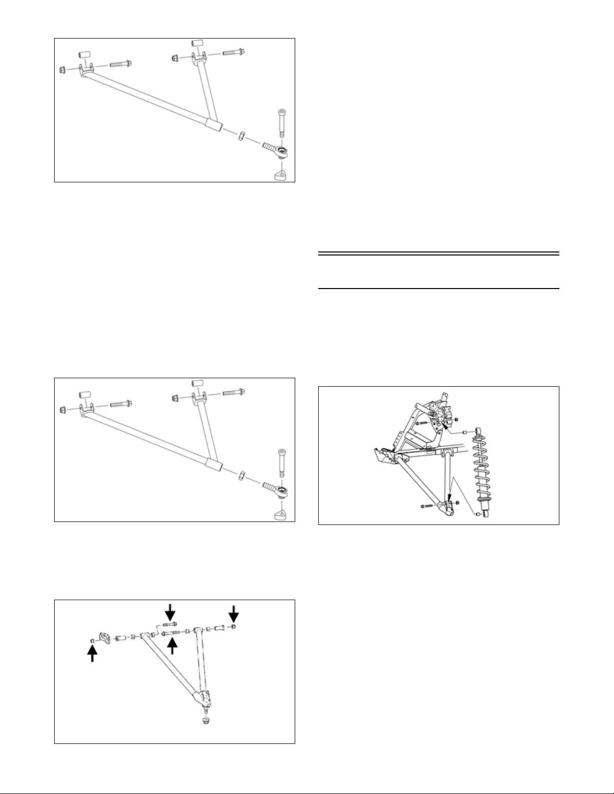
6. Remove the two cap screws and nyloc nuts securing
the lower arm to the chassis; then slide the boot from
the arm and remove the arm.
SNO-226A
7. Remove the two cap screws and lock nuts securing
the upper arm to the chassis.
14
3. Secure the A-arms to the spindle using one new lock
nut, a new machine screw and the existing tri-nut.
Tighten to the lock nut 45 ft-lb (61.2 N-m) and the
machine screw to 20 ft-lb (27.2 N-m).
NOTE: If the upper A-arm ball joint is being
replaced, make sure the ball joint is threaded in as far
as it can. Do not adjust outward or damage to the
A-arm or ball joint can occur.
4. Using a 19 mm wrench, tighten the hex nut against
the upper A-arm securely making sure to keep the
ball joint level with the spindle.
SNO-572
INSPECTING
1. Inspect the arm welded areas for cracks or any signs
of deterioration.
2. Inspect the bearings and axles for wear or damage.
3. Inspect the arm tubing for signs of twisting or bending.
4. Inspect mounting location of the chassis for cracks or
wear.
INSTALLING
1. Place the upper arm into position on the chassis and
secure with the cap screws, axles, and new lock nuts.
Tighten to 108 in.-lb (12.2 N-m).
5. Install the ski shock absorber and secure using the
existing cap screws and new lock nuts. Tighten to 24
ft-lb (32.6 N-m).
6. Install the steering boot and secure using the existing
push-rivets; then place the front skid plate into position. Secure with the Torx-head screws.
Ski Shock Absorber
REMOVING
1. Position the front of the snowmobile on a safety
stand taking all pressure off the skis.
2. Remove the cap screws securing the shock absorber
to the chassis and the lower A-arm; then remove the
shock absorber. Account for all mounting hardware.
SNO-572
2. Slide the lower arm into the steering boot; then place
the arm into position on the chassis with the existing
bushings. Secure with the cap screws and new lock
nuts and tighten to 65 ft-lb (88.4 N-m) (front) and 45
ft-lb (61.2 N-m) (rear).
SNO-226A
0753-180
CLEANING AND INSPECTING
1. Inspect the shock absorber seal area for signs of
excessive oil leakage.
2. Inspect the shock absorber mounting eyelet, bushings, and sleeve for wear or damage.
3. Inspect the threaded shock sleeve for damage or
wear.
INSTALLING
1. Using the shock spring tool, place the spring on the
shock absorber and secure with the retainer.
2. Adjust the retainer nut (spring adjuster) (if applicable) until the specified amount of threads are
exposed between the spring adjuster and the shock
housing (noted in removing) as an initial setting.
15
3. Install the bushings, sleeves, and spacers into each
shock end; then place the shock absorber into position and secure with the cap screws and new lock
nuts. Tighten the lock nuts to 24 ft-lb (32.6 N-m).
0753-180
Seat Assembly
REMOVING/INSTALLING SEAT
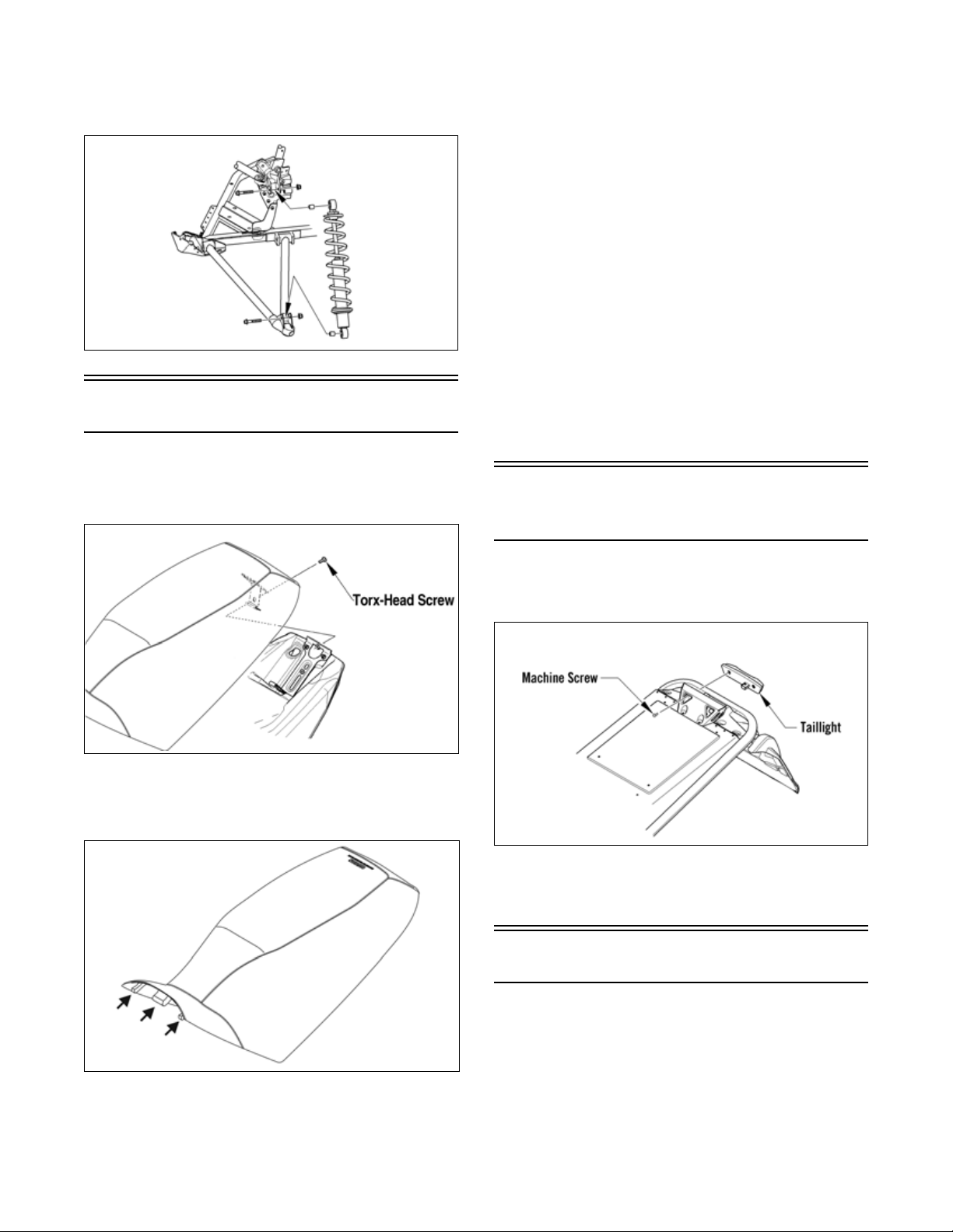
1. Remove the cap screw securing the rear of the seat;
then remove the seat.
2. Using a sharp tool, pry out all staples securing the seat
cover to the plastic seat base.
INSTALLING CUSHION
1. Position the cover over the seat foam and seat base.
Check to make sure it is positioned straight.
2. Fold the rear edge of the cushion down and around the
plastic base. Using a staple gun and 1/4 in. (6 mm) staples, staple the rear flap of the cushion to the plastic
base in the same areas as the original staples were
located. Position staples 1 in. (25 mm) apart.
3. Fold the sides of the cushion down around the bottom
edge of the plastic seat base. Position the staples in the
same area as the original staples were located.
NOTE: Note the cushion fit. If any wrinkles are
noted, remove by pulling the cushion material in the
appropriate direction before securing with staples.
4. Fold the front cushion material back and onto the plastic seat base. Check for wrinkles and secure with staples and two screws.
5. Install the seat assembly.
Taillight/Brake Light
Assembly
ONS-332
2. Route the front tab on the seat through the seat-base
hold-down bracket; then install the seat and secure
using the cap screw.
1. Remove the two machine screws securing the taillight to the taillight support; then disconnect the taillight harness connector.
SNO-511
2. Connect the taillight harness connector; then secure
the taillight to the taillight support with the two
machine screws. Tighten to 48 in.-lb (5.4 N-m).
Rear Bumper/Snowflap
REMOVING BUMPER
1. Remove all rivets securing the bumper to the chassis.
ONS-328
RE MOVING CUSHION
1. Remove the seat assembly.
16
INSTALLING BUMPER
1. Align the holes in the bumper with the existing holes
in the tunnel; then using new rivets, secure rear
bumper to the tunnel.
REMOVING SNOWFLAP
1. Remove the screws, washers, and nuts securing the
snowflap to the chassis.
2. Remove the snowflap.
INSTALLING SNOWFLAP
1. Position the snowflap with the mounting holes in the
chassis.
2. Secure the snowflap to the chassis using the existing
screws, washers, and nuts. Tighten to 62 in.-lb (7
N-m).
Windshield/Headlight
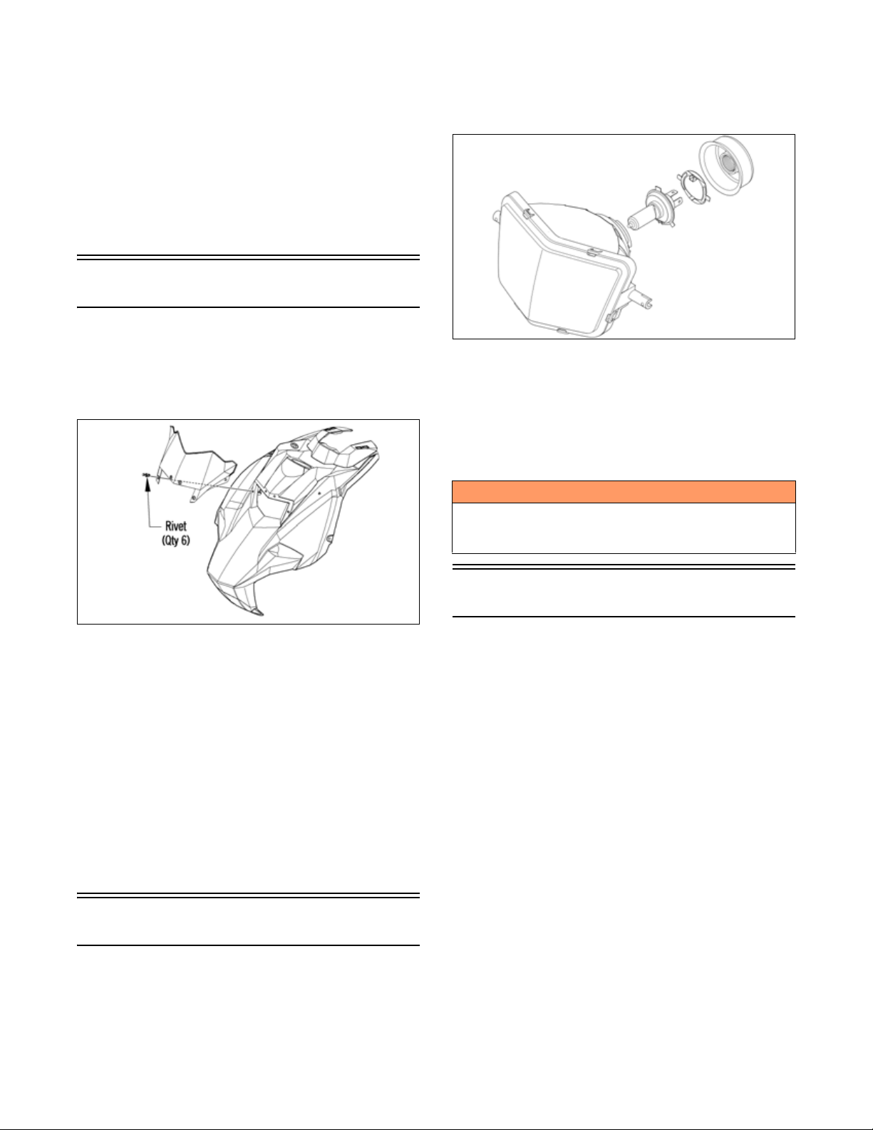
1. Disconnect the harness from the back of the bulb;
then remove the rubber boot.
2. Rotate the spring retainer securing the bulb in the
headlight; then carefully remove the bulb.
REMOVING
1. Remove both access panels and the hood.
2. Remove the rivets securing the windshield to the
hood. Remove the windshield.
0753-240
3. Disconnect the harness from the back of the bulb.
4. Remove the two pins securing the outer portion of
the headlight; then remove the screw securing the
lower portion of the headlight. Remove the headlight
from the hood.
INSTALLING
1. Install the headlight assembly into the hood tabs and
secure using the existing pins and screw.
2. Connect the harness to the bulb.
3. With the windshield in position, secure the windshield to the hood using the rivets. Tighten securely.
4. Install the hood and both access panels.
ONS-389
3. Install the bulb and retainer; then rotate the retainer
clockwise until it properly locks in place.
4. Install the rubber grommet; then connect the headlight harness connector to the bulb.
5. Check headlight aim (see Adjusting Headlight Aim
in this sub-section).
! WARNING
Do not operate the snowmobile unless headlight beam
is adjusted properly. An incorrectly adjusted beam will
not provide the operator the optimum amount of light.
Adjusting Headlight Aim
The headlight can be adjusted for vertical aim of the
HIGH/LOW beam. The geometric center of LOW beam
zone is to be used for vertical aiming.
1. Position the snowmobile on a level floor so the headlight is approximately 25 ft. (7.62 m) from an aiming
surface (wall or similar surface).
NOTE: There should be an “average” operating load
on the snowmobile when adjusting headlight aim.
2. Measure the distance from the floor to midpoint of
the headlight.
3. Using the measurement obtained in step 2, make a
horizontal mark on the aiming surface.
4. Make a vertical mark intersecting the horizontal mark
on the aiming surface directly in front of the headlight.
Headlight Bulb
NOTE: The bulb portion of the headlight is fragile.
HANDLE WITH CARE. When replacing the headlight bulb, the bulb assembly must first be removed
from the housing. Do not touch the glass portion of
the bulb. If the glass is touched, it must be cleaned
with a dry cloth before installing.
5. Engage the brake lever lock and start the engine.
Select the headlight dimmer switch LOW beam position. DO NOT USE HIGH BEAM.
Observe the headlight beam aim. Proper aim is when the
6.
most intense beam is centered on the vertical mark 5 cm
(2 in.) below the horizontal mark on the aiming surface.
7. Adjust the headlight using the adjusting screw on the
backside of the headlight housing until correct aim is
obtained. Shut the engine off; then disengage the
brake lever lock.
17
Engine
NOTE: Whenever a part is worn excessively,
cracked, or damaged in any way, replacement is necessary.
Engine Removing/Installing
This engine sub-section has been organized to show a
progression for removing/installing the Arctic Cat
engine. For consistency purposes, this sub-section shows
a complete and thorough progression; however, for efficiency it may be preferable to remove only those components needing to be addressed. Also, some components
may vary from model to model. The technician should
use discretion and sound judgment.
SPECIAL TOOLS
A number of special tools must be available to the technician when performing service procedures in this engine
section.
Description p/n
Drive Clutch Puller 0744-062
NOTE: Special tools are available from the Arctic
Cat Service Parts Department.
Removing
NOTE: For assembling purposes, note cable tie
locations securing the harness and cables to the chassis.
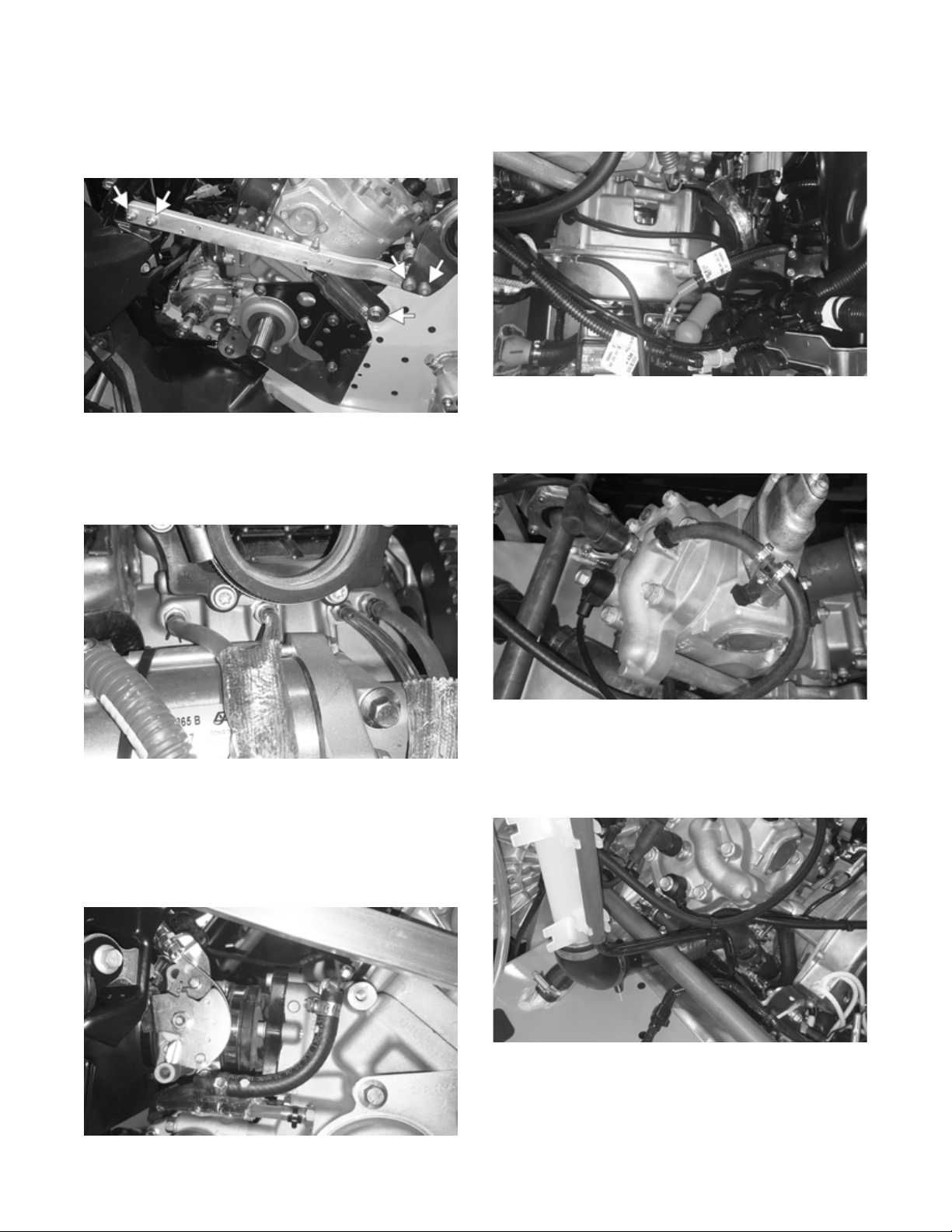
ZR-457
ZR-456
3. Disconnect the battery cables; then remove the screw
securing the battery hold-down bracket. Remove the
battery.
1. Remove both access panels and the hood; then
remove the exhaust temperature sensor from the
expansion chamber.
ZR-458
2. Remove all springs securing the expansion chamber
and resonator; then remove the expansion chamber
and resonator.
18
ZR-386
4. Remove the cap screw and washer securing the
driven clutch and slide the driven clutch (along with
the drive belt) off the driven shaft. Account for the
offset washers.
5. Remove the cap screw and washer securing the drive
clutch to the crankshaft.
6. Using Drive Clutch Puller, tighten the puller.
Remove the drive clutch.
CAUTION
Never attempt to substitute any other drive clutch puller
for the recommended puller or severe clutch or crankshaft damage will occur.
NOTE: If the drive clutch will not release, sharply
strike the head of the puller. Repeat this step until the
clutch releases.
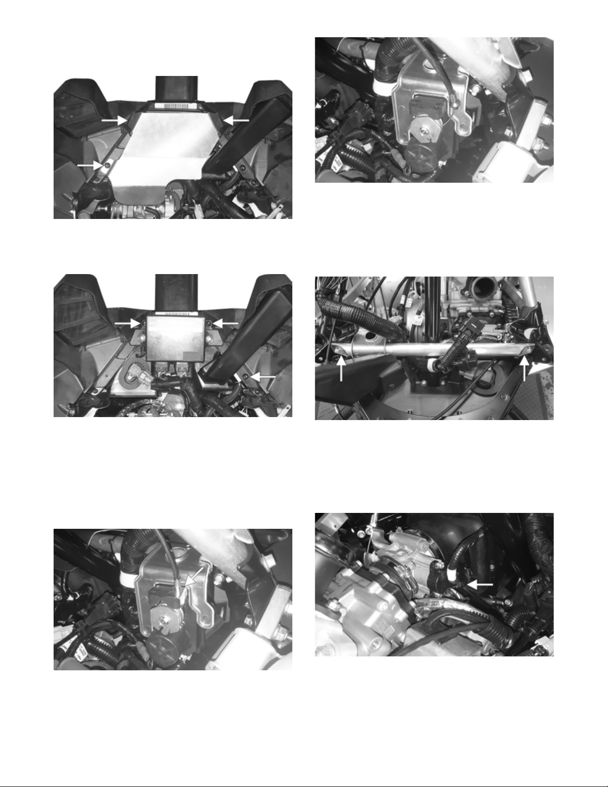
7. Remove the screw securing the heat shield to the
chassis; then remove the heat shield from the two
front locating pins and remove the heat shield.
ZR-461
8. Disconnect the ECM; then remove the screws securing the right and left-side fascia panels to the chassis.
Remove the panels and ECM as an assembly.
ZR-414
12. Remove the cap screws and lock nuts securing the
shock mount bracket support to the shock mount
brackets; then remove the shock mount bracket support.
NOTE: Take care to not drop the spar inserts and
nuts when removing the support.
ZR-460
9. Remove the cap screws securing the PTO-side front
spar to the steering support and shock mount bracket;
then remove the spar.
NOTE: Take care to not drop the spar inserts and
nuts when removing the spar.
10. Remove the servomotor cable holder; then pull the
cable housing down and out of the servomotor.
ZR-413
11. Slide each cable end out of the slot of the clutch; then
disconnect the connector from the servomotor.
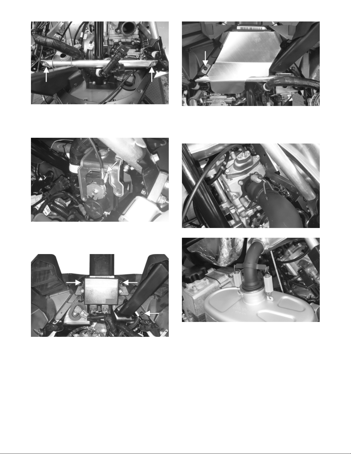
ZR-454
13. Drain the engine coolant (see Liquid Cooling System
in the Engine-Related Items section).
14. Loosen the two clamps securing the throttle body to
the intake manifold and the intake boot. Remove the
cable tie securing the TPS harness; then disconnect
the TPS connector.
ZR-415
15. Loosen the two clamps securing the throttle body
coolant hoses to the engine. Carefully remove the
throttle body and set aside.
19
ZR-451
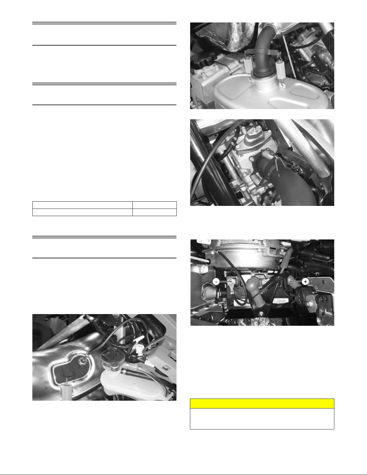
16. Loosen the two clamps securing the oil lines from
the engine. Pull the hoses from the oil fittings.
ZR-459
17. Remove the fuel line from the fuel pump and the fuel
rail. Remove the cable tie securing the coolant vent
hose to the line. Remove the fuel line.
ZR-452
19. Disconnect the harness connectors. Secure the harness out of the way.
20. Remove the cap screws and nuts securing the
left-side chassis support. Remove the support.
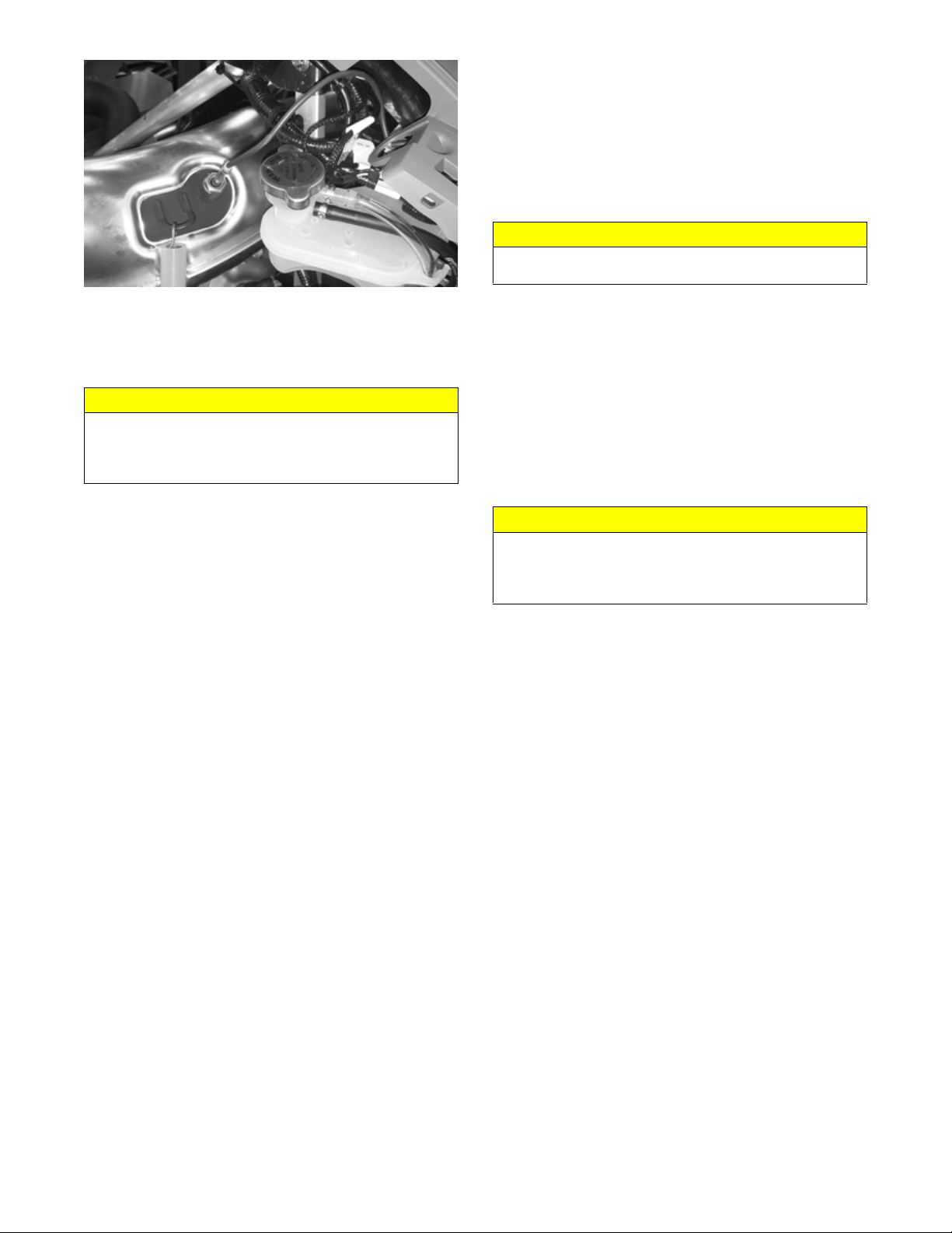
ZR-450
21. Loosen the clamp securing the coolant hose to the
rear of the engine. Remove the hose from the engine.
22. Remove the cap screw securing the MAG-side
bracket to the chassis.
ZR-453
! WARNING
The hose may be under pressure; remove it slowly to
release the pressure. Place an absorbent towel around
the connection to absorb gas.
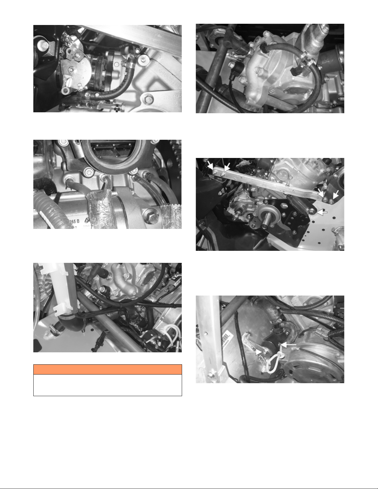
18. Loosen the clamps securing the cylinder and cylinder
head vent hoses. Remove the hoses and the spark
plug cap from the spark plug.
20
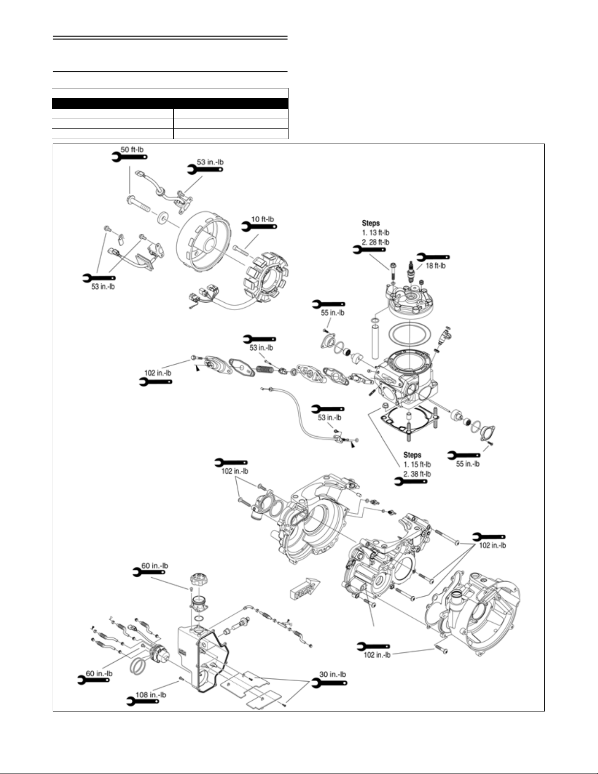
ZR-448
23. Remove the two cap screws and nuts securing the
front engine bracket to the chassis.
ZR-449
24. Carefully remove the engine assembly from the
chassis; then remove the cap screws and nuts securing the engine brackets to the engine.
Installing
ONS-388
4. Secure the starter motor to the front of the engine
using four new cap screws. Tighten to 25 ft-lb (34
N-m).
5. Carefully lower the engine into the engine compartment aligning the brackets and mounts with the
mounting locations.
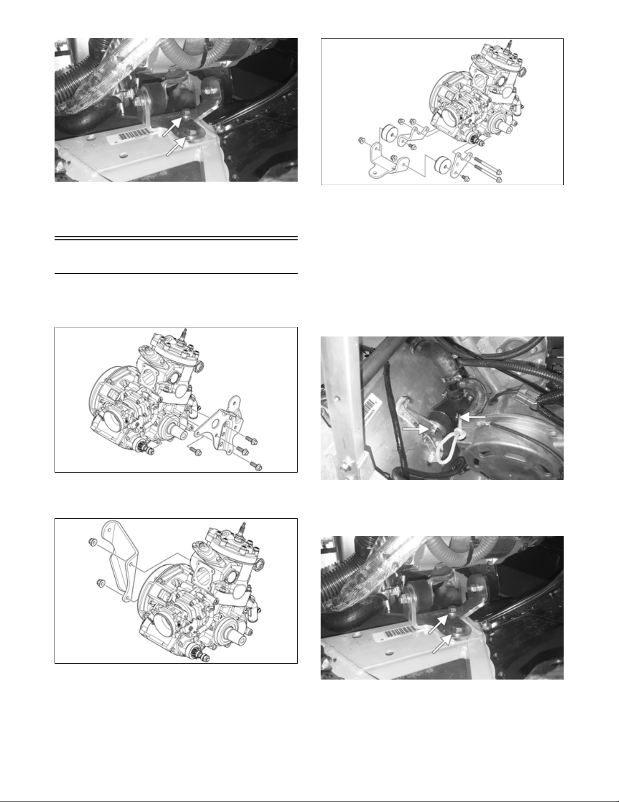
1. Secure the PTO-side engine mount to the engine
using four new cap screws. Tighten to 20 ft-lb (27.2
N-m).
ONS-386
2. Secure the MAG-side engine mount to the engine
using two new nuts. Tighten to 20 ft-lb (27.2 N-m).
6. Install the coolant hose to the rear of the engine using
the existing hose clamp. Tighten securely.
7. Secure the engine mount to the chassis using a new
cap screw. Tighten to 20 ft-lb (27.2 N-m).
ZR-448
8. Secure the front engine bracket to the chassis using
the existing cap screws and new nuts. Tighten to 35
ft-lb (47.6 N-m).
ONS-387
3. Secure the front engine mount assembly to the
engine using the existing cap screws and two new
nuts. Tighten to 20 ft-lb (27.2 N-m).
ZR-449
9. Install the left-side chassis support with the front two
and rear two mounting locations in the chassis.
Loosely secure using the existing cap screws and
new nuts.
21
10. Secure the support bracket (through the chassis) to
the engine mount using a new cap screw and the
existing washer. Tighten to 20 ft-lb (27.2 N-m).
11. Secure the front two cap screws to 96 in.-lb (10.8
N-m) and the rear two cap screws to 20 ft-lb (27.2
N-m).
16. Before connecting the wiring harness plug-ins, clean
the connectors and apply dielectric grease to the
seals; then connect all harness connectors making
sure all wiring and coolant hoses are routed properly
as noted in removing. Secure using cable ties.
ZR-464
ZR-450
12. Install the left-side front spar and secure using the
existing cap screws. Tighten to 25 ft-lb (34 N-m).
13. Install the four oil hoses to the engine and secure
using the existing clamps.
ZR-459
14. Position the throttle body assembly between the
intake assembly and the intake manifold. Secure
using the existing clamps. Tighten securely.
15. Install the coolant hoses from the throttle body to the
fittings on the engine. Secure using the existing
clamps. Tighten securely.
17. Connect the knock sensor connector to the main harness; then install the spark plug cap.
18. Install the cylinder and cylinder head vent hose.
ZR-452
19. Install the fuel line to the fuel rail until it fully clicks
onto the rail. Pull back on the fuel line to make sure
it is fully seated; then install the fuel line into the side
of the coolant bottle. Cable tie the coolant vent hose
to the fuel line.
ZR-451
22
ZR-453
20. Install the shock mount bracket support; then using
new lock nuts, secure the support to the shock mount
brackets and tighten to 20 ft-lb (27.2 N-m).
ZR-454
21. Insert the servomotor cable end into the front slot in
the clutch; then connect the servomotor connector.
Secure the cable with the holder.
ZR-413
22. Install the fascia panels (with ECM) and secure to
the chassis using the existing screws. Tighten
securely. Connect the ECM.
ZR-455
24. Install the resonator and secure with the springs; then
place the expansion chamber and gaskets into position and secure to the exhaust manifold and resonator
with the springs.
ZR-456
ZR-460
23. Position the heat shield onto the two front locating
pins; then secure it to the chassis with the screw.
Tighten securely.
ZR-457
25. Install the exhaust temperature sensor into the expansion chamber. Tighten to 34 ft-lb (46.2 N-m).
23
ZR-458
26. Place the drive clutch with drive belt into position on
the crankshaft and secure with the cap screw (threads
coated with oil) and high-collar washer. Tighten to
51 ft-lb (69,4 N-m).
CAUTION
When installing the drive clutch, do not tighten the
clutch cap screw with any kind of impact tool. Tighten
cap screw using a hand torque wrench only. Failure to
do so could result in stationary sheave damage.
NOTE: Before installing the drive clutch, be sure to
wipe clean both the crankshaft and clutch mounting
tapers using a clean towel.
27. Install the driven clutch on the driven shaft and
secure using the existing washer and cap screw.
Tighten to 20 ft-lb (27.2 N-m). Install the drive belt.
28. Fill the cooling system (see Liquid Cooling System
in the Engine-Related Items section).
29. Place the hood into position on the front end and
secure with the screw; then connect hood harness.
Install the side access panels.
CAUTION
Never run the engine with the hood harness disconnected or damage to the electrical system will result.
30. Start the engine and warm up to operating temperature; then verify that all components are functioning
properly and that coolant is circulating through the
cooling system properly.
31. After running the engine to the proper operating temperature, shut the engine off; then open the access
panels and inspect for any signs of coolant, gasoline,
or oil leakage.
32. Allow the engine to cool; then check the coolant
level and add coolant as necessary. Verify the tightening torque of the drive clutch.
CAUTION
If the engine had a major overhaul or if any major component was replaced, proper engine break-in procedures must be followed (see the General Information
section) or severe engine damage may result.
24
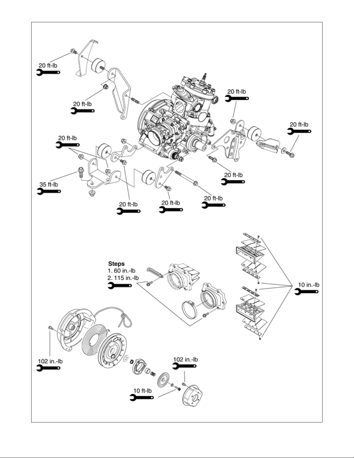
Assembly Schematic
Torque Specification Tolerances
Tor que Tol era nce
0-15 ft-lb (0-20 N-m) ±20%
16-39 ft-lb (21-53 N-m) ±15%
40+ ft-lb (54+ N-m) ±10%
400cc21_1
25
26
400cc21_2
Engine Servicing
This engine sub-section has been organized to show a
progression for servicing the Arctic Cat 4000 engine. For
consistency purposes, this sub-section shows a complete
and thorough progression; however, for efficiency it may
be preferable to disassemble only those components
needing to be addressed. Also, some components may
vary from model to model. The technician should use
discretion and sound judgment.
SPECIAL TOOLS
A number of special tools must be available to the technician when performing service procedures in this engine
section.
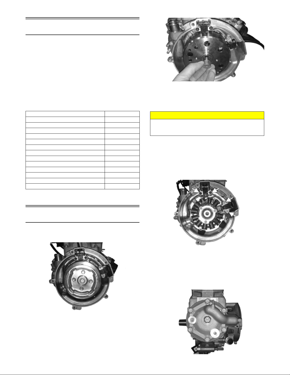
CWI-151
3. Using Flywheel Puller or suitable substitute, remove
the flywheel from the crankshaft by tightening the
puller bolt using an pneumatic gun. Account for the
key.
Description p/n
Ball Hone 0644-294
Flywheel Puller 0744-040
Flywheel Puller Insert 0644-567
Extractor Nut (Medium) 0643-074
Oil Seal Protector Tool 0644-219
14 mm Cylinder Wrench 0644-625
Piston Pin Puller 0644-328
Surface Plate 0644-016
Water Pump Bearing and Seal Tool Kit 0644-557
V Blocks 0644-535
Vacuum Test Pump 0644-131
Crankshaft Install and Removal Tool 0744-112
6 mm Adapter 0644-310
NOTE: Special tools are available from the Arctic
Cat Service Parts Department.
Disassembling
1. Remove the flywheel cap screw and washer; then
remove the cap screws securing the recoil cup.
CAUTION
To prevent damage to the crankshaft, do not thread
puller bolts more than 1/2 in. (12.7 mm) into the flywheel. Damage to the stator may result.
NOTE: To ensure the cleanliness of the flywheel
magnets, place the flywheel (with the magnets facing
upward) on a clean bench.
4. Remove the screws securing the timing sensors and
the ground wire. Remove the sensors and account for
the harness grommets.
CWI-152
5. Remove the screws securing the stator to the engine
housing. Route the stator lead wires out of the housing. Remove the stator assembly.
CWI-150
2. Install the Flywheel Puller Insert onto the end of the
crankshaft.
6. Remove the cap screws securing the cylinder head to
the cylinder. Remove the head and account for the
two O-rings and the coolant tube.
CWI-153
27

7. Remove the screws securing the engine housing to
the crankcase. Remove the housing and account for
the housing gasket and the dowel pins.
CWI-154
8. Remove the cap screw securing the fuel rail to the
cylinder. Remove the fuel rail and the injector.
Account for two O-rings.
CWI-158
11. Using Piston Pin Puller and medium Extractor Nut,
remove the piston pin from the piston.
CAUTION
DO NOT use any type of punch to drive the piston pin
free of the piston; damage may result. Use a piston-pin
puller only.
12. Lift the piston clear of the connecting rod and
remove the piston shims and bearing.
CWI-156
9. Remove the nuts securing the cylinder to the crankcase; then remove from the crankcase by lifting
straight up off the studs. Account for a gasket and the
alignment pins.
CAUTION
When removing the cylinder, be sure to support the piston to prevent damage to the crankcase and piston.
CWI-157
10. Remove the piston-pin circlips from the piston.
CWI-159
13. Remove the screws securing the intake manifold.
Remove the intake manifold and reed valve assembly.
CWI-155
14. Remove the cap screw and washers securing the
water pump impeller. Carefully remove the impeller
from the shaft.
28
 Loading...