

Arctic CAT 300 Utility, DVX 300 User Manual

300 UTILITY/DVX 300
2014
SERVICE MANUAL
[ATV]

FOREWORD
This Arctic Cat Service Manual contains service, maintenance, and troubleshooting information for the 2014 Arctic
Cat ATV 300 Utility/DVX 300 and is designed to aid service personnel in service-oriented applications.
This manual is divided into sections. Each section covers a specific ATV component or system and, in addition to the
standard service procedures, includes disassembling, inspecting, and assembling instructions. When using this manual
as a guide, the technician should use discretion as to how much disassembly is needed to address any given condition.
service manual is designed primarily for use by an Arctic Cat CatMaster Basic Level technician. The procedures found in
This
this manual are of varying difficulty, and certain service procedures in this manual require one or more special tools to
be completed. The technician should use sound judgement when determining which procedures can be completed
based on their skill level and access to appropriate special tools.
Arctic Cat ATV publications and decals display the words Warning, Caution, Note, and At This Point to emphasize
important information. The symbol ! WARNING identifies personal safety-related information. Be sure to follow the directive because it deals with the possibility of serious injury or even death. A CAUTION identifies unsafe
practices which may result in ATV-related damage. Follow the directive because it deals with the possibility of damaging part or parts of the ATV. The symbol NOTE: identifies supplementary information worthy of particular attention.
The symbol
and to improve clarity.
At the time of publication, all information, photographs, and illustrations were technically correct. Some photographs
used in this manual are used for clarity purposes only and are not designed to depict actual conditions. Because Arctic
Cat Inc. constantly refines and improves its products, no retroactive obligation is incurred. All materials and specifications are subject to change without notice.
AT THIS POINT directs the technician to certain and specific procedures to promote efficiency
Product Service and
Warranty Department
Arctic Cat Inc.
© 2013 Arctic Cat Inc. August 2013
®™ Trademarks of Arctic Cat Inc., Thief River Falls, MN 56701


TABLE OF CONTENTS
General Information........................................................... 2
General Specifications.................................................. 2
Torque Specifications.................................................... 3
Torque Conversions (ft-lb/N-m)..................................... 4
Break-In Procedure....................................................... 4
Gasoline - Oil - Lubricant .............................................. 4
Genuine Parts............................................................... 5
Preparation For Storage ............................................... 5
Preparation After Storage ............................................. 6
Periodic Maintenance/Tune-Up......................................... 7
Periodic Maintenance Chart ......................................... 7
Lubrication Points ......................................................... 8
Air Filter ........................................................................ 8
Valve/Tappet Clearance ................................................ 8
Testing Engine Compression ........................................ 9
Spark Plug .................................................................... 9
Muffler/Spark Arrester ................................................ 10
Engine Oil - Filter........................................................ 10
Rear Drive Lubricant (Utility)....................................... 11
Transmission Lubricant ............................................... 11
Drive Chain (DVX) ...................................................... 12
Driveshaft/Coupling (Utility) ........................................ 13
Nuts/Bolts/Cap Screws ............................................... 13
Headlight/Taillight- Brakelight ..................................... 13
Shift Lever................................................................... 13
Hydraulic Brake Systems............................................ 14
Auxiliary/Rear Hydraulic Brake ................................... 16
Burnishing Brake Pads ............................................... 18
Checking/Replacing V-Belt ......................................... 18
Steering/Frame/Controls ................................................. 20
Body............................................................................ 20
Steering Post Cover/Instrument Pod........................... 22
Steering Post/Tie Rods............................................... 23
Measuring/Adjusting Toe-In/Toe-Out........................... 25
Front Brake Lever/Master Cylinder Assembly............. 25
Auxiliary Brake Pedal/Master Cylinder Assembly ....... 26
Throttle Control ........................................................... 27
Troubleshooting .......................................................... 28
Engine/Transmission ....................................................... 29
Removing Engine/ Transmission................................. 30
Top-Side Components ................................................ 35
Removing Top-Side Components ............................... 35
Servicing Top-Side Components ................................ 37
Installing Top-Side Components ................................. 41
Left-Side Components ................................................ 43
Removing Left-Side Components............................... 43
Servicing Left-Side Components ................................ 44
Installing Left-Side Components................................. 50
Right-Side Components.............................................. 51
Removing Right-Side Components ............................ 52
Servicing Right-Side Components.............................. 57
Installing Right-Side Components .............................. 64
Center Crankcase Components ................................. 65
Separating Crankcase Halves .................................... 65
Disassembling Crankcase Half................................... 65
Servicing Center Crankcase Components ................. 65
Assembling Crankcase Half........................................ 66
Joining Crankcase Halves .......................................... 67
Installing Engine/Transmission ................................... 67
Troubleshooting .......................................................... 70
Fuel/Lubrication/Cooling ................................................ 73
Carburetor .................................................................. 73
Throttle Cable Free-Play............................................. 77
Engine RPM (Idle) ...................................................... 77
Gas Tank .................................................................... 77
Gas Tank Valve ........................................................... 78
Gas/Vent Hoses.......................................................... 78
Oil Flow Chart............................................................. 78
Oil Pump..................................................................... 79
Liquid Cooling System................................................ 79
Radiator...................................................................... 79
Hoses/Thermostat ...................................................... 80
Fan ............................................................................. 80
Water Pump................................................................ 80
Troubleshooting .......................................................... 81
Electrical System............................................................. 82
RPM Limiter................................................................ 82
Testing Electrical Components ................................... 82
Electrical Connections................................................ 82
Switches ..................................................................... 82
Battery ........................................................................ 82
Brakelight Switch (Auxiliary)....................................... 83
Brakelight Switch (Handlebar Control) ....................... 83
Coolant Temperature and Cooling Fan Switches........ 84
Fan Motor ................................................................... 84
Fuse Block.................................................................. 84
Fuses.......................................................................... 85
Ignition Coil................................................................. 85
Indicator Lights (DVX)................................................. 86
LCD Gauge Assembly................................................ 86
Ignition Switch ............................................................ 87
Handlebar Control Switches....................................... 87
Magneto Coils ............................................................ 88
Starter Motor .............................................................. 88
Starter Relay .............................................................. 88
CDI Unit...................................................................... 89
Regulator/Rectifier...................................................... 89
Start-in-Gear Relay .................................................... 89
Headlights .................................................................. 90
Taillight - Brakelight .................................................... 90
Ignition Timing ............................................................ 90
Troubleshooting .......................................................... 91
Drive System.................................................................... 93
Rear Drive Assembly Schematics .............................. 93
Rear Drive Axle (DVX) ................................................ 93
Rear Drive Axle (Utility) .............................................. 96
Troubleshooting Drive System.................................. 105
Troubleshooting Brake System................................. 105
Suspension .................................................................... 106
Front and Rear Suspension Assembly Schematics.. 106
Front Shock Absorbers............................................. 106
Rear Shock Absorber ............................................... 107
Swing Arm ................................................................ 108
Front A-Arms ............................................................ 111
Wheels and Tires...................................................... 113
Troubleshooting ........................................................ 114
1
General Information
NOTE: Some photographs and illustrations used in
this manual are used for clarity purposes only and
are not designed to depict actual conditions.
NOTE: Whenever a part is worn excessively, cracked,
or damaged in any way, replacement is necessary.
General Specifications
CHASSIS DVX Utility
Dry Weight (approx) 192.8 kg (425 lb) 216 kg (477 lb)
Length (overall) 171.9 cm (67.7 in.) 187 cm (73.6 in.)
Height (overall) 113.5 cm (44.7 in.) 111.8 cm (44.0 in.)
Width (overall) 113.5 cm (44.7 in.) 105.1 cm (41.40 in.)
Tire Size (Front)
Tire Inflation Pressure
Spark Plug Type NGK DPR7EA-9
Spark Plug Gap 0.8-0.9 mm (0.032-0.036 in.)
Gas Tank Capacity 12.8 L (3.4 U.S. gal.)
Reserve Capacity 4.54 L (1.2 U.S. gal.)
Engine Oil Capacity 1.6 L (1.7 U.S. qt) 1.4 L (1.5 U.S. gt)
Transmission (Overhaul)
Lubricant Capacity (Change)
Gasoline (recommended) 87 Octane Regular Unleaded
Engine Oil (recommended) Arctic Cat ACX All Weather (Synthetic)
Cooling System Capacity 1.4 L (1.5 U.S. qt)
Rear Drive Capacity N/A 150 ml (5 fl oz)
Rear Drive Lubricant N/A SAE Approved
Brake Fluid DOT 4
Taillight/Brakelight 12V/5W/21W
Headlight 12V/35W (2)
Carburetor Type Keihin CVK32
Main Jet 112
Starter Jet 60
Slow Jet 38
Pilot Screw Setting (turns) 1 3/4
Needle Jet 4.0/3.6
Jet Needle NLRA
Idle RPM 1250-1350
Float Arm Height 17.0 mm (0.67 in.)
Throttle Cable Free-Play (at lever) 1-4 mm (1/16-3/16 in.)
Ignition Timing 5° BTDC (“F” mark) @ 1000
Spark Plug Cap 4500-6150 ohms
Ignition Coil Resistance (primary)
Ignition Coil Peak Voltage (primary/CDI) 9.6-16.4 DC volts
Magneto Coil Resistance (trigger)
Stator Coil Peak Voltage (trigger) 1.1-1.4 DC volts
Magneto Output (approx) 220W @ 5000 RPM
Stator Coil Output (no load) 40-60 AC volts@3500 RPM
AT21x7-10
(Rear)
AT20 x 11-9
2
(Front)
2
(Rear)
0.28 kg/cm
0.25 kg/cm
MISCELLANY
400 ml (13.5 fl/oz)
300 ml (10.1 fl/oz)
FUEL SYSTEM
ELECTRICAL SYSTEM
RPM
(secondary)
(charging)
2.4-3.0 ohms
12,300-16,600 ohms
105-110 ohms
Less than 1 ohm
AT22x7-10
AT22 x 10-10
2
(4 psi)
2
(3.5 psi)
600 ml (20.3 fl/oz)
500 ml (16.9 fl/oz)
80W-90 Hypoid
CAMSHAFT AND CYLINDER HEAD
Cam Lobe Height (min) (intake)
Rocker Arm/Shaft Clearance (max) 0.1 mm
Cylinder Head/Cover Distortion (max) 0.05 mm
(exhaust)
34.15 mm
34.05 mm
CYLINDER, PISTON, AND RINGS
Piston Skirt/Cylinder Clearance (max) 0.12 mm
Cylinder Bore 72.705-72.715 mm
Piston Diameter 18 mm from Skirt End
(max)
Bore x Stroke 72.7 x 65.2 mm
Cylinder Trueness (max) 0.05 mm
Piston Ring to Groove Clearance (max)
(1st/2nd)
Piston Ring End Gap - Installed (top)
Piston Pin Bore (max) 17.06 mm
Piston Pin Outside Diameter (min) 16.96 mm
(middle)
(oil)
72.625 mm
0.09 mm
0.15-0.30 mm
0.30-0.45 mm
0.20-0.70 mm
CRANKSHAFT
Connecting Rod (small end inside
diameter) (max)
Connecting Rod (big end side-to-side) 0.05-0.40 mm
Connecting Rod (small end deflection)
(max)
Crankshaft (web-to-web) 55.15-55.20 mm
Crankshaft Runout (max) 0.1 mm
Oil Pressure at 60°C (140°F) (above)
@ 3000 RPM (below)
17.06 mm
1mm
0.3 kg/cm² (4.3 psi)
0.7 kg/cm² (10 psi)
TRANSMISSION
Clutch Release Screw 1/8 turn back
Drive Plate (fiber) Thickness (min) 2.4 mm
Drive Plate (fiber) Tab (min) 11 mm
Driven Plate (warpage) (max) 0.1 mm
Clutch Spring Length (min) 27.5 mm
Clutch Wheel Inside Diameter (max) Scuffing of contact surface
Clutch Shoe Lining Thickness 0.5 mm
Clutch Engagement RPM 2000 ± 200
Clutch Lock-Up RPM 3400 ± 300
VALVES AND GUIDES
Valve/Tappet Clearance (intake/exhaust)
(cold engine)
Valve Guide/Stem Clearance (intake)
(max) (exhaust)
Valve Spring Free Length (min) (inner)
Valve Spring Tension @ 18.0 mm (intake) 10.2-11.8 kg (22.5-26.0 lb)
Valve Spring Tension (exhaust)
@ 21.5 mm
(outer)
0.1 mm
0.06 mm
0.08 mm
29.4 mm
39.0 mm
19.05-22.0 kg (42.0-48.5 lb)
Specifications subject to change without notice.
2
Torque Specifications
STEERING COMPONENTS
Part Part Bolted To
Handlebar Clamp Cap Screw Steering Head 18 24
Steering Post Support Block Frame 17 23
Steering Post Nut Steering Post 50 68
Upper And Lower Ball Joint Nut Steering Knuckle 22 30
Tie Rod End Nut Steering Knuckle 15 20
Tie Rod Lock Nut Tie Rod 15 20
ELECTRICAL COMPONENTS
Starter Motor Lead Cable Nut Starter 36
Starter Motor Mounting Bolt Crankcase 9 12
EXHAUST COMPONENTS
Exhaust Pipe Engine 25 34
Muffler Mounting Bolt Frame 25 34
BRAKE COMPONENTS
Brake Hose Union Bolt Master Cylinder/
Brake Bleed Screw Caliper 56
Brake Caliper Mounting Cap Screw Steering Knuckle/
Master Cylinder (Front) Handlebar 13 18
Brake Pad Mounting Pin (Front/Rear) Brake Caliper 13 18
Brake Caliper Slide Pin (Front/Rear) Brake Caliper 25 34
Front Brake Line Nut Brake Line/Junction
Brake Caliper (Rear) Swing Arm Housing 25 34
Caliper
Swing Arm
Block
SUSPENSION COMPONENTS (Front)
A-Arm Pivot Nut Frame 32 44
Front Shock Absorber Mounting Nut*
(Upper/Lower)
Frame 29 39
SUSPENSION COMPONENTS (Rear)
Left Pivot Bolt (Utility) Swing Arm 36
Right Pivot Bolt (Utility) Swing Arm 82 112
Left Pivot Lock Nut (Utility) Left Pivot Bolt 82 112
Swing Arm Pivot Nut (DVX) Frame 50 68
Rear Shock Absorber Mounting Nut
(Upper/Lower)
Axle Housing Cap Screw (Utility) Final Drive Gear
Axle Housing Cap Screw (DVX) Swing Arm 29 39
Frame/Swing Arm 29 39
Case
DRIVE TRAIN COMPONENTS
Engine Mounting Through-Bolt Frame 29 39
Engine Mounting Bracket Cap Screw Frame 16 22
Rear Axle Housing (Utility) Swing Arm 40 54
Rear Axle Housing (DVX) Tube 29 39
Gear Case Swing Arm 50 68
Pinion Nut Shaft 72 98
Gear Case Cover (8 mm)
Hub Nut (Front) Front/Spindle 50 68
Wheel Lug Nut Hub 40 54
Hub Nut (Rear) Axle 72 98
Rear Axle Nut* (Utility) Axle 72 98
Rear Axle Nut* (DVX) Axle 86 117
(10 mm)
Gear Case 193626
*w/Red Loctite #271
Torque
ft-lb N-m
5
in.-lb
25 34
5
in.-lb
25 34
25 34
5
in.-lb
40 54
49
ENGINE/TRANSMISSION
Part Part Bolted To
Cylinder Head Cylinder 7 10
Cylinder Nut Crankcase 7 10
Camshaft Holder Cylinder Head 18 24
Bevel Drive Gear (Utility) Driveshaft 72 98
Magneto Rotor/Flywheel Crankshaft 47 64
Bevel Driven Gear (Utility) Driven Shaft 72 98
Output Drive Sprocket Lock Plate
(DVX)
Crankcase Cap Screw Crankcase 8 11
Engine Oil Screen/Filter Cap Crankcase 11 15
Shift Cam Stopper Plug* (Utility) Left Case 20 27
Shift Cam Stopper Plug* (DVX) Transmission Case 35 48
Camshaft Chain Tensioner Adjuster Cam Chain
Cam Chain Tensioner Cover Bolt Tensioner 24
Starter Ratchet Crankshaft 68 92
Camshaft Chain Tensioner Mount Cylinder Head 9 12
Camshaft Chain Tension Spring
Holder Plug
Centrifugal Clutch Housing Driveshaft 40 54
Timing Plug Right Case 16 22
Driven Pulley Retaining Nut Driven Shaft
Drive Plate Nut* Fixed Driven Face 43 59
Drive Pulley Nut Crankshaft 72 98
Engine Oil Drain Plug Crankcase 21 29
Transmission Drain Plug Transmission 21 29
Transmission Case Cover Transmission 20 27
Driveshaft 43 59
Tensioner
Cam Chain
Tensioner
(Transmission)
Torque
ft-lb N-m
912
in.-lb
36
in.-lb
43 59
3
4
3

Torque Conversions
(ft-lb/N-m)
ft-lb N-m ft-lb N-m ft-lb N-m ft-lb N-m
1 1.4 26 35.4 51 69.4 76 103.4
2 2.7 27 36.7 52 70.7 77 104.7
3 4.1 28 38.1 53 72.1 78 106.1
4 5.4 29 39.4 54 73.4 79 107.4
5 6.8 30 40.8 55 74.8 80 108.8
6 8.2 31 42.2 56 76.2 81 110.2
7 9.5 32 43.5 57 77.5 82 111.5
8 10.9 33 44.9 58 78.9 83 112.9
9 12.2 34 46.2 59 80.2 84 114.2
10 13.6 35 47.6 60 81.6 85 115.6
11 15 36 49 61 83 86 117
12 16.3 37 50.3 62 84.3 87 118.3
13 17.7 38 51.7 63 85.7 88 119.7
14 19 39 53 64 87 89 121
15 20.4 40 54.4 65 88.4 90 122.4
16 21.8 41 55.8 66 89.8 91 123.8
17 23.1 42 57.1 67 91.1 92 125.1
18 24.5 43 58.5 68 92.5 93 126.5
19 25.8 44 59.8 69 93.8 94 127.8
20 27.2 45 61.2 70 95.2 95 129.2
21 28.6 46 62.6 71 96.6 96 130.6
22 29.9 47 63.9 72 97.9 97 131.9
23 31.3 48 65.3 73 99.3 98 133.3
24 32.6 49 66.6 74 100.6 99 134.6
25 34 50 68 75 102 100 136
Break-In Procedure
During the break-in period, a maximum of 1/2 throttle is
recommended; however, brief full-throttle accelerations
and variations in driving speeds contribute to good
engine break-in.
After the completion of the break-in period, the engine
oil and oil filter should be changed. Other maintenance
after break-in should include checking of all prescribed
adjustments and tightening of all fasteners.
Gasoline - Oil - Lubricant
RECOMMENDED GASOLINE
The recommended gasoline to use is 87 minimum octane
regular unleaded. In many areas, oxygenates are added to
the gasoline. Oxygenated gasolines containing up to 10%
ethanol or 5% methane are acceptable gasolines.
When using ethanol blended gasoline, it is not necessary
to add a gasoline antifreeze since ethanol will prevent the
accumulation of moisture in the fuel system.
CAUTION
Do not use white gas. Only Arctic Cat approved gaso-
line additives should be used.
RECOMMENDED ENGINE OIL
CAUTION
Any oil used in place of the recommended oil could
cause serious engine damage. Do not use oils which
contain graphite or molybdenum additives. These oils
can adversely affect clutch operation. Also, not recom-
mended are racing, vegetable, non-detergent, and cas-
tor-based oils.
The recommended oil to use is Arctic Cat ACX All
Weather synthetic engine oil, which has been specifically
formulated for use in this Arctic Cat engine. Although
Arctic Cat ACX All Weather synthetic engine oil is the
only oil recommended for use in this engine, use of any
API certified SM 0W-40 oil is acceptable.
A new ATV and an overhauled ATV engine require a
“break-in” period. The first 10 hours (or 200 miles) are
most critical to the life of this ATV. Proper operation during this break-in period will help assure maximum life
and performance from the ATV.
During the first 10 hours (or 200 miles) of operation,
always use less than 1/2 throttle. Varying the engine
RPM during the break-in period allows the components
to “load” (aiding the mating process) and then “unload”
(allowing components to cool). Although it is essential to
place some stress on the engine components during
break-in, care should be taken not to overload the engine
too often. Do not pull a trailer or carry heavy loads during the 10-hour break-in period.
When the engine starts, allow it to warm up properly. Idle
the engine several minutes until the engine has reached
normal operating temperature. Do not idle the engine for
excessively long periods of time.
4
OILCHARTJ
RECOMMENDED REAR DRIVE LUBRICANT (Utility)
The recommended lubricant is Arctic Cat Gear Lube or
an equivalent gear lube which is SAE approved 80W-90
hypoid. This lubricant meets all of the lubrication
requirements of the Arctic Cat ATV rear drive.
CAUTION
Any lubricant used in place of the recommended lubricant could cause serious rear drive damage.
Genuine Parts
When replacement of parts is necessary, use only genuine
Arctic Cat ATV parts. They are precision-made to ensure
high quality and correct fit. Refer to the appropriate Illustrated Parts Manual for the correct part number, quantity,
and description.
RECOMMENDED TRANSMISSION LUBRICANT
The recommended lubricant is Arctic Cat Gear Lube or an
equivalent gear lube which is SAE approved 80W-90 hypoid. This lubricant meets all the lubrication requirements of
the Arctic Cat ATV front differential and rear drive.
CAUTION
Any lubricant used in place of the recommended lubricant could cause serious front differential/rear drive
damage.
FILLING GAS TANK
! WARNING
Always fill the gas tank in a well-ventilated area. Never
add fuel to the ATV gas tank near any open flames or
with the engine running. DO NOT SMOKE while filling
the gas tank.
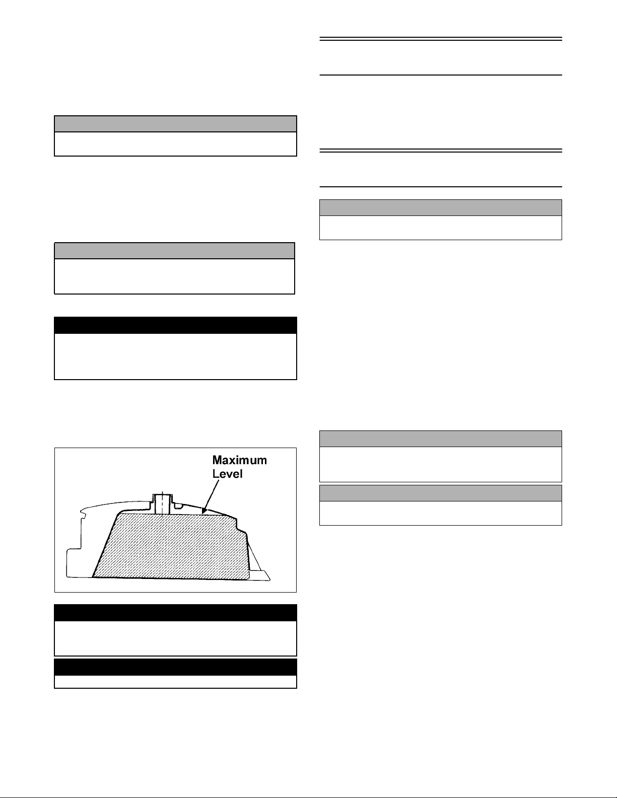
Since gasoline expands as its temperature rises, the gas
tank must be filled to its rated capacity only. Expansion
room must be maintained in the tank particularly if the
tank is filled with cold gasoline and then moved to a
warm area.
Preparation For Storage
CAUTION
Prior to storing the ATV, it must be properly serviced to
prevent rusting and component deterioration.
Arctic Cat recommends the following procedure to prepare the ATV for storage.
1. Clean the seat cushion (cover and base) with a damp
cloth and allow it to dry.
2. Clean the ATV thoroughly by washing dirt, oil,
grass, and other foreign matter from the entire ATV.
Allow the ATV to dry thoroughly. DO NOT get
water into any part of the engine or air intake.
3. Either drain the gas tank or add Fuel Stabilizer to the
gas in the gas tank. Remove the air filter housing
cover and air filter. Start the engine and allow it to
idle; then using Arctic Cat Engine Storage Preserver,
slowly inject the preserver into the air filter opening
for a period of 10 to 20 seconds; then stop the
engine. Install the air filter and housing cover.
CAUTION
Rapid induction of oil or any liquid into a four-cycle
engine can cause “hydraulic-lock” resulting in severe
engine damage.
ATV0049B
! WARNING
Do not overflow gasoline when filling the gas tank. A
fire hazard could materialize. Always allow the engine to
cool before filling the gas tank.
! WARNING
Do not over-fill the gas tank.
Tighten the gas tank cap securely after filling the tank.
CAUTION
If the interior of the air filter housing is dirty, clean the
area before starting the engine.
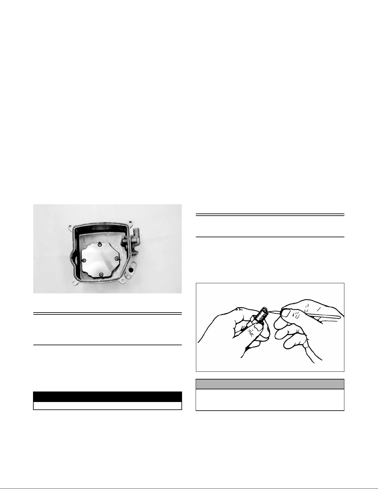
4. Drain the carburetor float chamber.
5. Plug the exhaust hole in the exhaust system with a
clean cloth.
6. Apply light oil to the upper steering post bushing and
plungers of the shock absorbers.
7. Tighten all nuts, bolts, cap screws, and screws. Make
sure rivets holding components together are tight.
Replace all loose rivets. Care must be taken that all
calibrated nuts, cap screws, and bolts are tightened to
specifications.
8. Fill the cooling system to the FULL line in the cooling system reservoir with properly mixed coolant.
5
9. Disconnect the battery cables; then remove the battery, clean the battery posts and cables, and store in a
clean, dry area.
CAUTION
This maintenance-free battery should be charged at the
recommended rate every 30 days or permanent damage
may occur if the battery completely discharges.
10. Store the ATV indoors in a level position.
CAUTION
Avoid storing outside in direct sunlight and avoid using
a plastic cover as moisture will collect on the ATV causing rusting.
Preparation After
Storage
Taking the ATV out of storage and correctly preparing it
will assure many miles and hours of trouble-free riding.
Arctic Cat recommends the following procedure to prepare the ATV.
1. Clean the ATV thoroughly.
2. Clean the engine. Remove the cloth from the exhaust
system.
3. Check all control wires and cables for signs of wear
or fraying. Replace if necessary.
4. Change the engine oil and filter.
5. Check the coolant level and add properly mixed
coolant as necessary.
6. Charge the battery; then install. Connect the battery
cables.
CAUTION
The ignition switch must be in the OFF position prior to
installing the battery or damage may occur to the ignition system.
CAUTION
Connect the positive battery cable first; then the negative.
7. Check the entire brake systems (fluid level, pads,
etc.), all controls, headlights, taillight, brakelight,
and headlight aim; adjust or replace as necessary.
8. Tighten all nuts, bolts, cap screws, and screws making sure all calibrated nuts, cap screws, and bolts are
tightened to specifications.
9. Check tire pressure. Inflate to recommended pressure
as necessary.
10. Make sure the steering moves freely and does not
bind.
11. Check the spark plug. Clean or replace as necessary.
6

Periodic Maintenance/
Tune-Up
Description p/n
Compression Tester Kit 0444-213
Tappet Adjuster 0444-189
SPECIAL TOOLS
Cat Service Parts Department.
A number of special tools must be available to the technician when performing service procedures in this section.
Refer to the current Special Tools Catalog for the appropriate tool description.
Periodic Maintenance
Chart
A = Adjust I = Inspect C = Clean L = Lubricate D = Drain R = Replace T = Tighten
NOTE: Special tools are available from the Arctic
Item
Battery I I C
Air Filter/Drain Tube I I C* R
Valve/Tappet Clearance I I A
Spark Plug I I R (4000 Mi
Muffler/Spark Arrester CR
Gas/Vent Hoses I I R (2 Yrs)
Gas Tank Valve IC
Throttle Cable I I C-L A-R
Carb Float Chamber D*
Engine RPM (Idle) I I A
Engine Oil Level I A
Engine Oil - Screen* C C** C
Drive Chain (DVX) I I C-L
Rear Drive Lubricant (Utility) I I R A
Transmission Lubricant I I R A
Tires/Air Pressure I I A-R
Steering Components I I I R
V-Belt I IR
Suspension (Ball joint boots, tie
rods, differential and rear drive
bellows)
Nuts/Cap Screws/Screws I I T
Ignition Timing I
Headlight/Taillight-Brakelight I I R
Switches I I R
Shift Lever IA-L
Choke Cable I C-L R
Recoil Starter (Utility) I C-R
Handlebar Grips I R
Handlebars I I R
Gauges/Indicators I I R
Frame/Welds/Racks I I l
Electrical Connections lC
Complete Brake System (Hydraulic
and Auxiliary)
Brake Pads I I* R
Brake Fluid I I R (2 Yrs)
Brake Hoses I I R (4 Yrs)
Coolant/Cooling System I I R (2 Yrs)
Initial Service After
Break-In (First
Month or 100 Miles)
I I l* R
II C L-R
Every
Day
Every Month or
Every 100 Miles
* Service/Inspect more frequently when operating in adverse conditions. ** When using Arctic Cat ACX All Weather synthetic oil, oil
change interval can be increased to every 1,000 miles or every year.
Every 3 Months
or Every 300
Miles
Every 6 Months
or Every 500
Miles
Every Year
or Every
1500 Miles
As
Needed
or 18 Mo)
7
Lubrication Points
It is advisable to lubricate certain components periodically to ensure free movement. Apply light oil to the
components using the following list as reference.
A. Throttle Lever Pivot/Cable Ends
B. Brake Lever Pivot
C. Auxiliary Brake Pivot/Clevis
D. Choke Cable Upper End
E. Shift Lever/Ball Joints
F. Idle RPM Screw
4. Fill a wash pan larger than the filter with a non-flammable cleaning solvent; then dip the filter in the solvent and wash it.
NOTE: Foam Filter Cleaner and Foam Filter Oil are
available from Arctic Cat.
5. Dry the filter.
6. Put the filter in a plastic bag; then pour in air filter oil
and work the filter.
CAUTION
A torn air filter can cause damage to the ATV engine. Dirt
and dust may get inside the engine if the element is torn.
Carefully examine the element for tears before and after
cleaning it. Replace the element with a new one if it is torn.
7. Clean any dirt or debris from inside the air cleaner.
Make sure no dirt enters the carburetor.
Air Filter
Use the following procedure to remove the filter and
inspect and/or clean it.
CLEANING AND INSPECTING FILTER
CAUTION
Failure to inspect the air filter frequently if the vehicle is used
in dusty, wet, or muddy conditions can damage the engine.
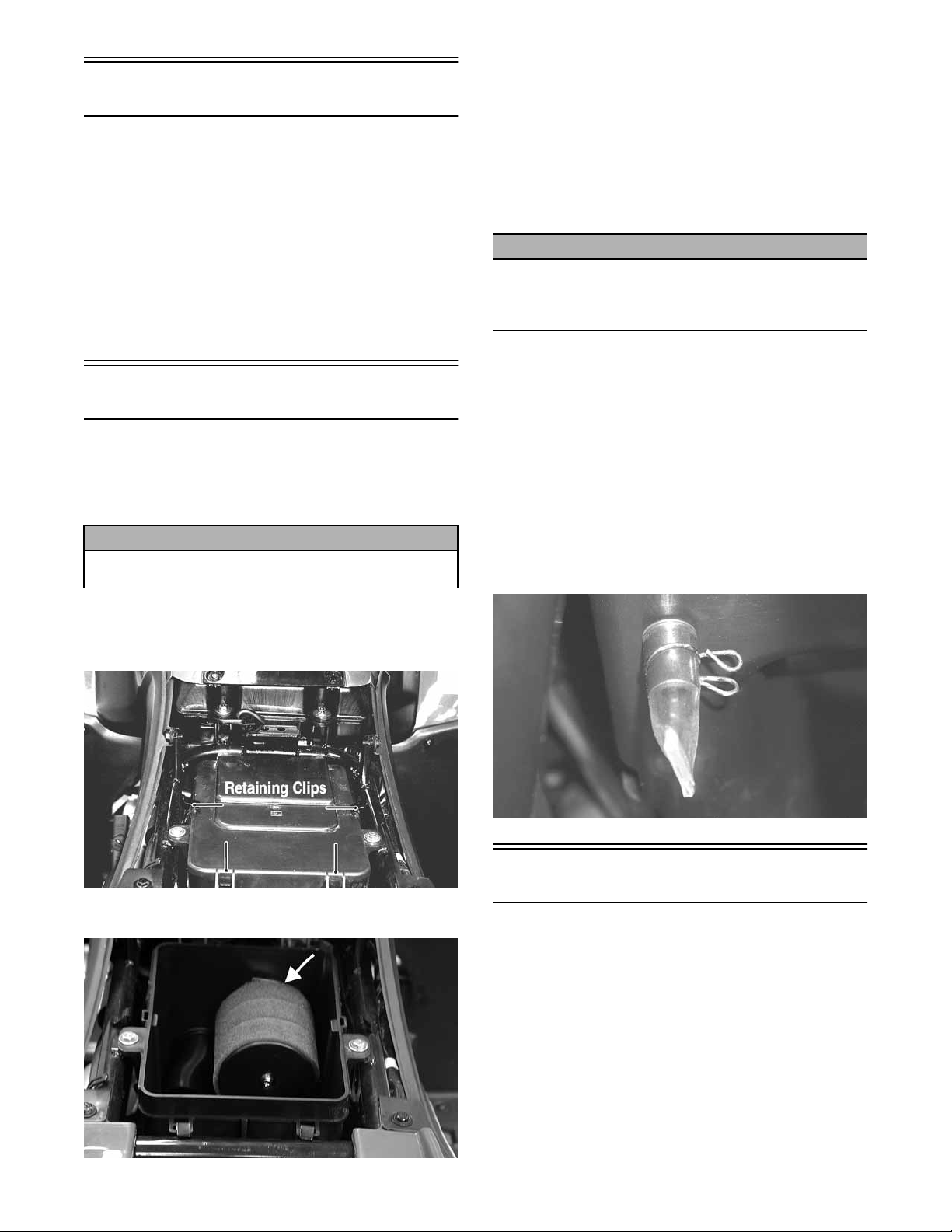
1. Remove the seat.
2. Remove the air filter housing cover from the retaining clips.
8. Place the filter in the air filter housing making sure it
is properly seated and secure with the clamp.
9. Install the air filter housing cover and secure with the
retaining clips; then install the seat making sure it
locks securely.
CHECKING/DRAINING DRAIN TUBE
Periodically check the drain tube for gasoline or oil accumulation. If noticed, remove the drain tube cap from
beneath the housing and drain the gasoline or oil into a
suitable container; then install and secure the tube cap.
KM114
3. Loosen the clamp; then remove the filter.
8
KM095A
KM097B
Valve/Tappet Clearance
To check and adjust valve/tappet clearance, use the following procedure.
NOTE: The seat assembly, side panels, and gas
tank must be removed for this procedure.
1. Remove the timing inspection plug; then remove the
cylinder head cover (see Engine/Transmission Removing Top-Side Components).
2. Rotate the crankshaft so the “T” mark on the flywheel aligns with the index mark on the right-side
crankcase cover.
NOTE: At this point, the round hole in the camshaft
gear should be up.
3. Place Tappet Adjuster onto the jam nut securing the
tappet adjuster screw; then rotate the adjuster dial
clockwise until the end is seated in the tappet
adjuster screw.
5. While holding the throttle lever in the full-open position, crank the engine over with the electric starter
until the gauge shows a peak reading (five to 10
compression strokes).
4. While holding the adjuster dial in place, use the
adjuster handle and loosen the jam nut; then rotate the
tappet adjuster screw clockwise until friction is felt.
5. Align the adjuster handle with one of the marks on
the adjuster dial.
6. While holding the adjuster handle in place, rotate the
adjuster dial counterclockwise until proper valve/
tappet clearance is attained.
NOTE: Refer to the appr opriate specifications in Engine/
T ransmission for the proper valve/tappet clearance.
NOTE: Rotating the adjuster dial counterclockwise
will open the valve/tappet clearance by 0.05 mm
(0.002 in.) per mark.
7. While holding the adjuster dial at the proper clearance setting, tighten the jam nut securely with the
valve adjuster handle.
8. Place the cylinder head cover with a new O-ring into
position; then tighten the cover securely.
NOTE: The compression should be within a range
of 210-230 psi in the full-open throttle position.
6. If compression is abnormally low, verify the following items.
A. Starter cranks engine over.
B. Gauge functions properly.
C. Throttle lever in the full-open position.
D. Valve/tappet clearance correct.
E. Valve not bent or discolored.
F. Valve seat not discolored.
NOTE: To service valves, see Engine/Transmission -
Servicing Top Side Components.
7. Pour 29.5 ml (1 fl oz) of oil into the spark plug hole,
attach the gauge, and test compression.
8. If compression is now evident, service the piston
rings (see Engine/Transmission - Servicing Top Side
Components).
Spark Plug
KM703
9. Install the timing inspection plug.
Testing Engine
Compression
To test engine compression, use the following procedure.
1. Remove the high tension lead from the spark plug.
2. Using compressed air, blow any debris from around
the spark plug.
! WARNING
Always wear safety glasses when using compressed air.
3. Remove the spark plug; then attach the high tension
lead to the plug and ground the plug on the cylinder
head well away from the spark plug hole.
A light brown insulator indicates that the plug is correct.
A white or dark insulator indicates that the engine may
need to be serviced or the carburetor may need to be
adjusted. To maintain a hot, strong spark, keep the plug
free of carbon.
ATV-0051
CAUTION
Before removing the spark plug, make sure to clean the
area around the spark plug. Dirt could enter engine
when removing or installing the spark plug.
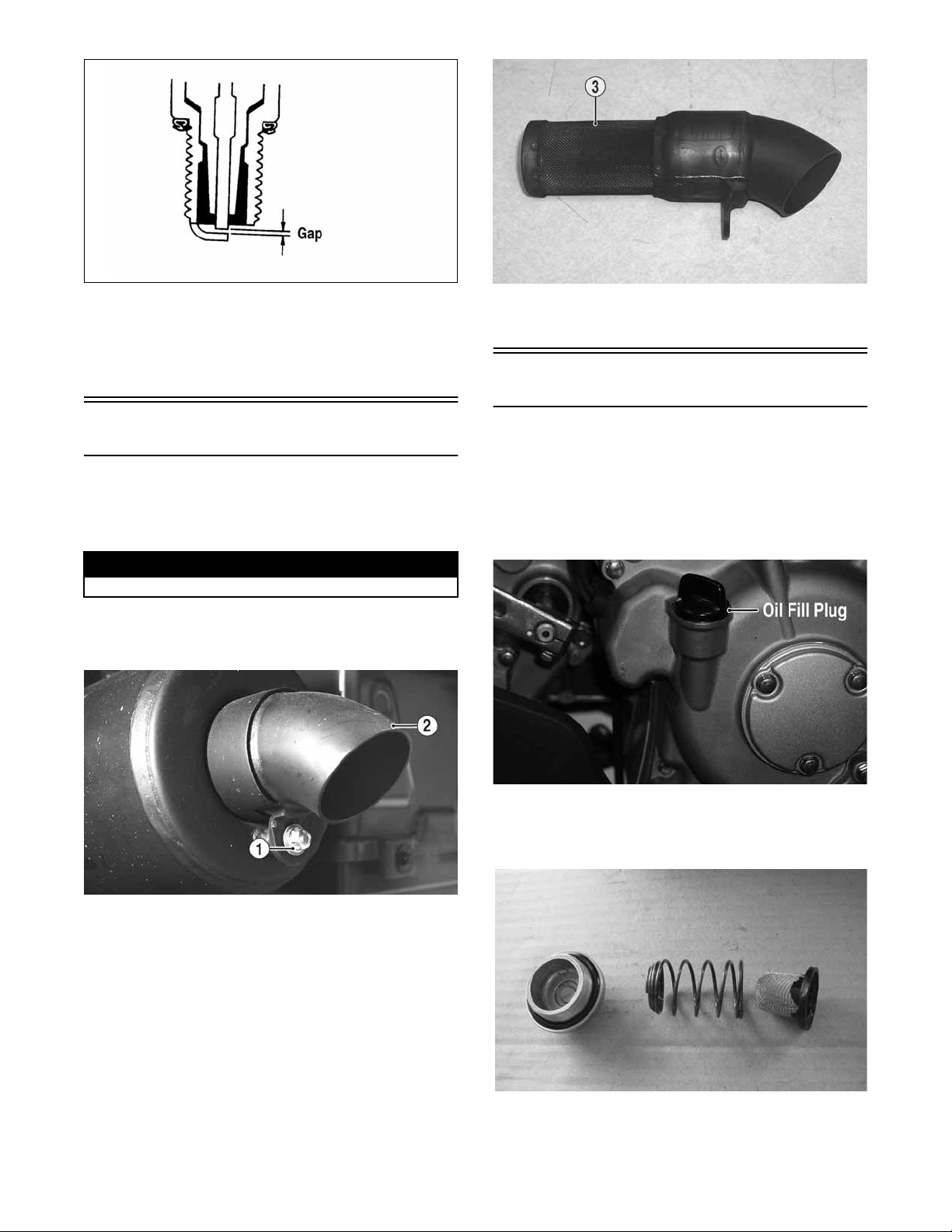
Adjust the gap to 0.8-0.9 mm (0.032-0.036 in.) for proper
ignition. Use a wire feeler gauge to check the gap.
4. Attach the gauge from Compression Tester Kit.
NOTE: The engine must be warm and the battery
must be fully charged for this test.
9
.
ATV0052B
When installing the spark plug, make sure to tighten it
securely. A new spark plug should be tightened 1/2 turn
once the washer contacts the cylinder head. A used spark
plug should be tightened 1/8-1/4 turn once the washer
contacts the cylinder head.
Muffler/Spark Arrester
The muffler has a spark arrester which must be periodically cleaned. At the intervals shown in the Periodic
Maintenance Chart, clean the spark arrester using the following procedure.
! WARNING
Wait until the muffler cools to avoid burns.
1. Remove the cap screw (1) securing the spark arrester
(2) to the muffler assembly; then carefully remove
the spark arrester.
KM140B
3. Install the spark arrester and secure with the cap
screw. Tighten securely.
Engine Oil - Filter
Replace the engine oil and clean the screen/filter at the
scheduled intervals. The engine should always be warm
when the oil is changed so the oil will drain easily and
completely.
1. Park the ATV on level ground.
2. Loosen the oil fill plug.
KM139A
2. Using a soft wire brush, clean the carbon from the
screen (3) taking care not to tear or damage the screen.
10
KM126A
3. Remove the screen/filter cap from the bottom of the
engine and drain the oil into a drain pan. Account for
a spring, O-ring, and screen/filter.
DSC02248
4. Clean the screen/filter in parts-cleaning solvent; then
inspect the O-ring and replace if damaged.

5. Install the screen/filter, spring, and screen/filter cap
into the bottom of the engine and tighten to 11 ft-lb.
2. If low, add SAE approved 80W-90 hypoid gear lube
as necessary.
6. Remove the oil fill plug and pour in 1.6 L (1.7 U.S.
qt) of the recommended oil into the fill hole; then
install the oil fill plug.
CAUTION
Any oil used in place of the recommended oil could
cause serious engine damage. Do not use oils which
contain graphite or molybdenum additives. These oils
can adversely affect clutch operation. Also, not recommended are racing, vegetable, non-detergent, and castor-based oils.
7. Start the engine (while the ATV is outside on level
ground) and allow it to idle for a few minutes.
8. Turn the engine off and wait approximately one minute.
Check the oil level in the engine oil inspection windo w.
The oil level should be visible through the window. If
oil is not visible, add recommended oil until the oil
level is visible between the lines of the window.
To change the lubricant, use the following procedure.
1. Place the ATV on level ground.
2. Loosen the fill plug.
3. Remove the cap screws securing the rear drive gear
guard; then remove the guard.
4. Drain the lubricant into a drain pan by removing the
drain plug from the bottom of the rear drive.
NOTE: If the rear drive lubricant is contaminated
with water, inspect the drain plug, fill plug, and/or
bladder.
5. After all the lubricant has been drained, install the
drain plug and tighten securely. Install the rear drive
gear guard and tighten the cap screws securely.
6. Pour the appropriate amount of recommended lubricant into the fill hole. Remove the level plug and
check for appropriate level.
7. Install the fill plug.
CAUTION
Water entering the outer end of the axle will not be able
to enter the rear drive unless the seals are damaged.
KM127A
9. Inspect the area around the screen/filter cap for leaks.
Rear Drive Lubricant
(Utility)
Check and change the lubricant according to the Periodic
Maintenance Chart. When changing the lubricant, use
approved SAE 80W-90 hypoid gear lube. To check lubricant, use the following procedure.
1. Remove the rear drive level plug; the lubricant level
should be at the threads of the plug.
Transmission Lubricant
Change the lubricant according to the Periodic Maintenance Chart. When changing the lubricant, use approved
SAE 80W-90 hypoid gear lube.
To change the lubricant, use the following procedure.
1. Place the ATV on level ground.
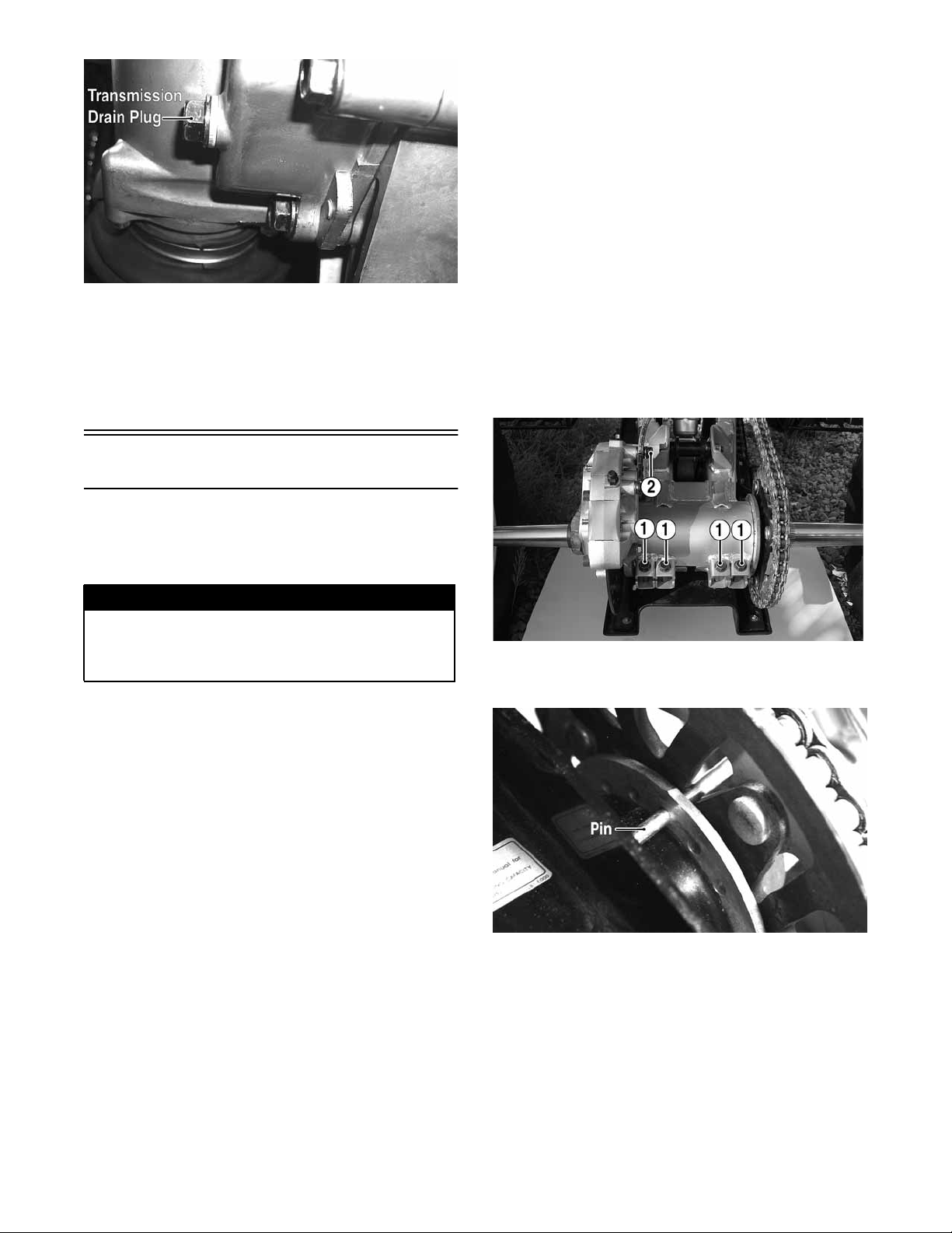
2. Loosen the fill plug; then remove the transmission
drain plug and drain the transmission lubricant.
KM104A
KM131A
11
KM106A
3. Install the drain plug and tighten securely.
4. Remove the fill plug and pour the appropriate
amount of recommended lubricant into the fill hole.
5. Install the fill plug and tighten securely.
6. Check the area around the drain plug for leakage.
Drive Chain (DVX)
NOTE: This ATV is equipped with an O-ring type
roller chain. Each link incorporates small O-rings to
seal out water and dirt. Care should be taken to
choose cleaning solutions and lubricants that are
suitable for O-ring type chains.
1. Using a suitable, nonflammable cleaning solution,
thoroughly wash the chain and sprockets.
2. Allow the chain to dry; then apply a dry, graphitebased lubricant to the chain.
NOTE: The drive chain should be lubricated with a
dry, graphite-based chain lubricant. By using a dry,
graphite-based chain lubricant, dirt build-up on the
drive chain will be minimized.
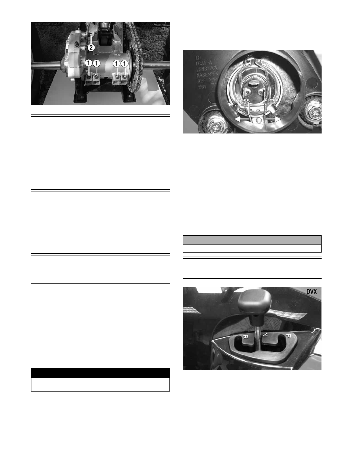
ADJUSTING TENSION
1. Loosen the four cap screws (1) at the rear of the axle
housing; then loosen the cap screw (2) on the front of
the brake caliper.
Drive chain condition and adjustment should be
inspected each day before the ATV is operated. Always
follow the following guidelines for inspecting and servicing the drive chain.
! WARNING
Failure to inspect and maintain the drive chain can be
hazardous. Operating the ATV with the drive chain in
poor condition or improperly adjusted can cause an
accident resulting in possible injury.
INSPECTING
Inspect the drive chain for any of the following conditions.
A. Loose pins.
B. Loose or cracked rollers.
C. Dry or rusted links.
D. Kinked or binding links.
E. Excessive wear.
The presence of any of the conditions requires drive
chain replacement.
NOTE: If the drive chain is worn or damaged, the
sprockets may also be worn or damaged. Inspect the
sprockets for worn, broken, or damaged teeth.
Always inspect the sprockets when a new drive chain
is being installed.
CLEANING AND LUBRICATING
The drive chain should be cleaned and lubricated frequently to prolong chain and sprocket life. Use the following procedure to clean and lubricate the chain.
KM902A
2. Install an appropriate pin through the axle hub and
rear sprocket.
KM158A
3. With a person seated on the ATV, check chain tension at the mid-point of the chain.
NOTE: Chain “slack” should be within a range of
30-40 mm (1.2-1.6 in.).
4. Push the ATV forward to tighten chain tension; push
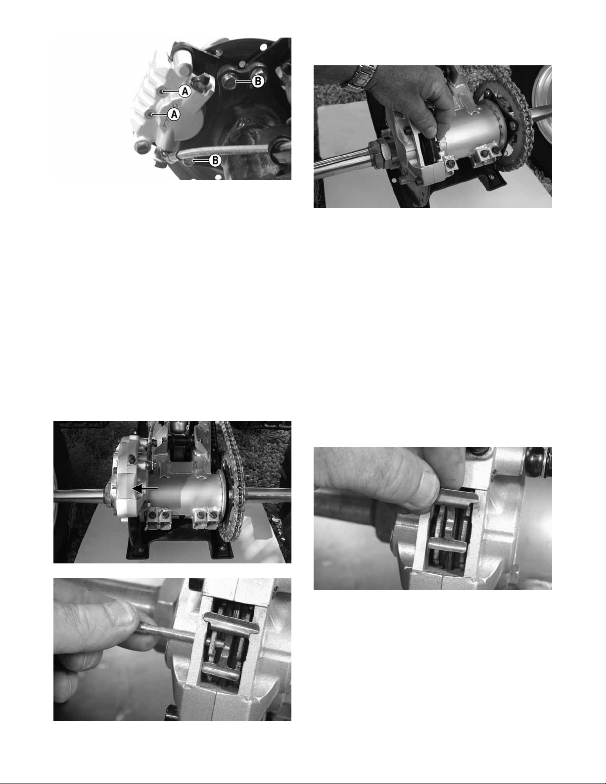
the ATV backward to loosen chain tension.
5. Tighten the four cap screws (1) to 29 ft-lb; then
tighten the cap screw (2) to 29 ft-lb.
12
KM902A
Driveshaft/Coupling
(Utility)
The following drive system components should be
inspected periodically to ensure proper operation.
A. Spline lateral movement (slop).
B. Coupling not cracked, damaged, or worn.
2. Using care not to bend or deform the spring clip,
release the two ends of the spring clip from the light
housing; then remove the bulb from the headlight
housing.
KM192A
3. Install the new bulb into the headlight housing; then
secure with the spring clip.
4. Connect the three-wire connector to the bulb; then
install the boot.
To replace the taillight-brakelight bulb, use the following
procedure.
Nuts/Bolts/Cap Screws
Tighten all nuts, bolts, and cap screws. Make sure rivets
holding components together are tight. Replace all loose
rivets. Care must be taken that all calibrated nuts, bolts,
and cap screws are tightened to specifications (See General Information).
Headlight/Taillight-
Brakelight
Each time the ATV is used, lights should be checked for
proper function. Turn the ignition switch to the LIGHTS
position; the headlights and taillight should illuminate.
Test the brakelight by compressing the brake lever. The
brakelight should illuminate.
NOTE: The bulb portion of the headlight is fragile.
HANDLE WITH CARE. When replacing the headlight
bulb, do not touch the glass portion of the bulb. If the
glass is touched, it must be cleaned with a dry cloth
before installing. Skin oil residue on the bulb will
shorten the life of the bulb.
1. Remove the two screws and remove the lens cover.
2. Push the bulb in and turn it counterclockwise.
3. Install the new bulb by turning it clockwise while
pushing in.
4. Install the lens cover.
CAUTION
Tighten the lens cover screws only until they are snug.
Shift Lever
! WARNING
Do not attempt to remove the bulb when it is hot. Severe
burns may result.
To replace the headlight bulb, use the following procedure.
1. Remove the boot from the back of the headlight
housing; then remove the three-wire connector from
the bulb.
KM363A
13

KM124B
CHECKING ADJUSTMENT
Stop the ATV completely and shift the transmission into
the R position. The reverse gear indicator light should be
illuminated.
! WARNING
Never shift the ATV into reverse gear when the ATV is
moving as it could cause the ATV to stop suddenly
throwing the operator from the ATV.
If the reverse gear indicator light does not illuminate
when shifted to the reverse position, the switch may be
faulty, the fuse may be blown, the bulb may be faulty, a
connection may be loose or corroded, or the lever may
need adjusting. To adjust, proceed to Adjusting Shift
Lever.
ADJUSTING SHIFT LEVER
1. Place the shift lever in the N (neutral) position; then
set the engine stop switch to the STOP position and
turn the ignition switch to the RUN position. The
neutral indicator light should illuminate.
NOTE: If the neutral indicator light does not illumi-
nate, adjustment of the shift linkage will be required.
To adjust, proceed to step 2.
KM179A
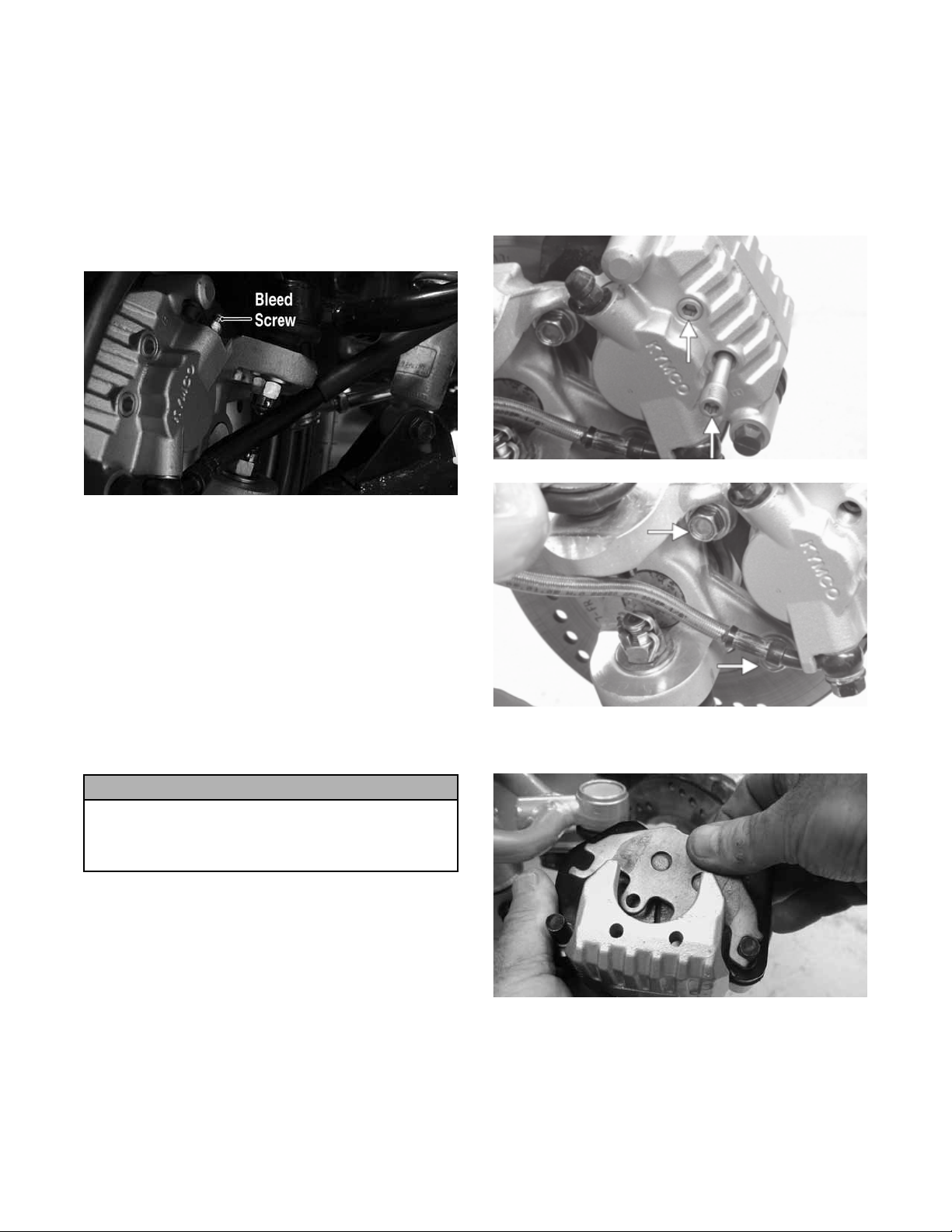
Hydraulic Brake Systems
CHECKING/BLEEDING
The hydraulic brake systems have been filled and bled at
the factory. To check and/or bleed a hydraulic brake system, use the following procedure.
1. With the master cylinder in a level position, check
the fluid level in the reservoir. If the level in the reservoir is not visible in the sight glass, add DOT 4
brake fluid.
2. Loosen the jam nuts on both ends of the shift rod and
turn the shift rod until the neutral light illuminates.
Tighten the jam nuts securely.
KM313
NOTE: On the DVX, the neutral position in the trans-
mission is indexed by passing a Phillips screwdriver
through the transmission shift arm and into the index
hole in the transmission cover.
14
KM113
KM137
2. Compress the brake lever/pedal several times to
check for a firm brake. If the brake is not firm, the
system must be bled.
3. To bleed the brake system, use the following procedure.
A. Remove the cover and fill the reservoir with DOT
4 Brake Fluid.
3. If thickness of either brake pad is less than 1.0 mm
(0.039 in.), the brake pad must be replaced.
B. Install and secure the cover; then slowly compress
the brake lever several times.
C. Remove the protective cap, install one end of a
clear hose onto the REAR bleed screw, and direct
the other end into a container; then while holding
slight pressure on the brake lever, open the bleed
screw and watch for air bubbles. Close the bleed
screw before releasing the brake lever. Repeat this
procedure until no air bubbles are present.
KM116A
NOTE: During the bleeding procedure, watch the
reservoir sight glass very closely to make sure there
is always a sufficient amount of brake fluid. Failure to
maintain a sufficient amount of fluid in the reservoir
will result in air in the system.
NOTE: The brake pads should be replaced as a set.
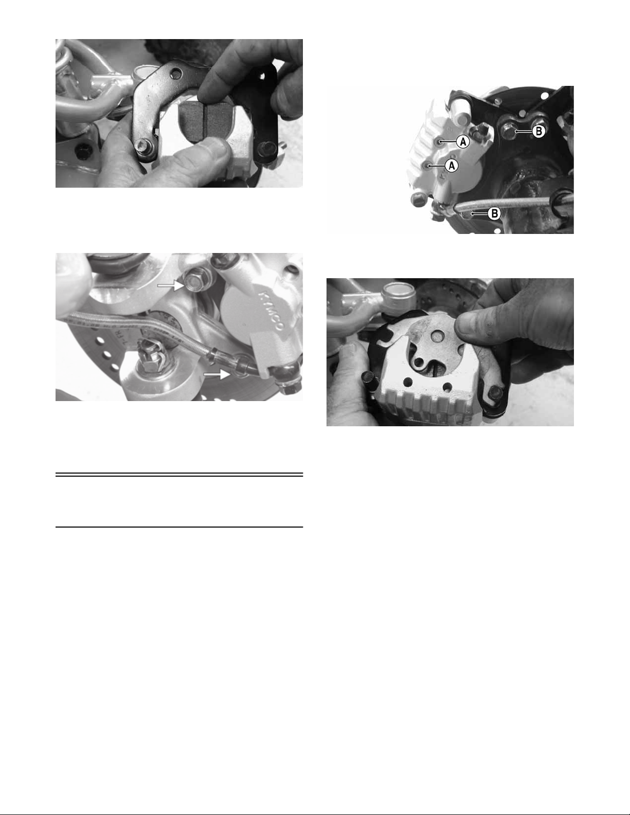
4. To replace the brake pads, use the following procedure.
A. With the wheel removed, remove the brake pad
alignment pins from the caliper; then remove the
mounting cap screws.
KM265A
D. At this point, perform steps B and C on the
FRONT RIGHT bleed screw; then move to the
FRONT LEFT bleed screw and follow the same
procedure.
4. Carefully check the entire hydraulic brake system
that all hose connections are tight, the bleed screws
are tight, the protective caps are installed, and no
leakage is present.
CAUTION
This hydraulic brake system is designed to use DOT 4
brake fluid only. If brake fluid must be added, care must
be taken as brake fluid is very corrosive to painted surfaces.
INSPECTING HOSES
Carefully inspect the hydraulic brake hoses for cracks or
other damage. If found, the brake hoses must be replaced.
CHECKING/REPLACING FRONT PADS
The clearance between the brake pads and brake discs is
adjusted automatically as the brake pads wear. The only
maintenance that is required is replacement of the brake
pads when they show excessive wear. Check the thickness of each of the brake pads as follows.
KM266A
B. Remove the caliper from the disc; then compress
the caliper holder and remove the brake pads.
KM267
C. Install new brake pads; then install the two brake
pad alignment pins.
1. Remove a front wheel.
2. Measure the thickness of each brake pad.
15
KM268
D. Spread the brake pads and place the brake caliper
over the disc. Secure with the mounting cap
screws. Tighten the cap screws to 25 ft-lb; then
tighten the alignment pins to 13 ft-lb.
2. Remove the left rear wheel.
3. Remove the two brake pad alignment pins (A); then
remove the mounting cap screws (B).
KM273A
4. Remove the caliper from the disc; then compress the
caliper holder and remove the brake pads.
KM266A
5. Install the wheel. Tighten in a crisscross pattern to 40
ft-lb.
6. Burnish the brake pads (see Burnishing Brake Pads
in this section).
Auxiliary/Rear Hydraulic
Brake
CHECKING
1. With the engine off, the transmission in neutral, and
the reverse lever in the forward position, press the
brake pedal and attempt to move the ATV.
2. If the rear wheels are locked, it is functioning properly.
3. If the rear wheels are not locked, it must be repaired
or bled.
BLEEDING
To bleed the auxiliary brake, see Hydraulic Brake Systems - CHECKING/BLEEDING in this section.
KM267
Inspecting and Measuring
1. Inspect the pads for gouges, chips, or wear.
2. Inspect the disc for gouges, grooves, cracks, and
warpage.
3. Using a calipers, measure the thickness of each brake
pad.
4. If the thickness of either brake pad is less than 1.0
mm (0.039 in.), the brake pad must be replaced.
NOTE: The brake pads should be replaced as a set.
Installing
1. Install new brake pads; then install the two brake pad
alignment pins.
2. Spread the brake pads and place the brake caliper
over the disc; then secure with the mounting cap
screws (B). Tighten the cap screws to 25 ft-lb; then
tighten the alignment pins (A) to 13 ft-lb.
MEASURING/REPLACING REAR BRAKE PADS (Utility)
Removing
1. Support the ATV on a suitable support stand.
16
KM273A
3. Install the wheel. Tighten in a crisscross pattern to 40
ft-lb.
4. Remove the ATV from the support stand.
NOTE: Whenever installing new pads, the new pads
must be burnished (see Burnishing Brake Pads in
this section).
MEASURING/REPLACING REAR/ AUXILIARY BRAKE PADS (DVX)
Removing
NOTE: The brake caliper on the DVX contains two
sets of brake pads. The front pads are controlled by
the main brake lever and the rear pads are controlled
by the auxiliary brake pedal.
1. Remove the brake pad dust cover; then remove the
clip pin and pull the brake pad retaining pin out of
the caliper.
2. Remove the brake spring plate; then remove the
brake pads.
KM905
Inspecting and Measuring
1. Inspect the pads for gouges, chips, or wear.
2. Inspect the disc for gouges, grooves, cracks, and
warpage.
3. Using a calipers, measure the thickness of each brake pad.
4. If the thickness of any brake pad is less than 1.0 mm
(0.039 in.), the brake pad must be replaced.
NOTE: The brake pads should be replaced as a set.
5. Using a calipers, measure the thickness of the disc. If
any portion of the disc is less than 3.00 mm (0.12
in.), the disc must be replaced (see Drive System Troubleshooting Brake System).
Installing
1. Install the brake pads in the caliper; then insert the
brake spring plate.
KM902B
KM244
KM245
2. Install the brake pad retaining pin and secure with
the clip pin; then install the dust cover.
17
3. Burnish the brake pads.
KM244
KM279
2. Remove the front and rear V-belt housing cooling
ducts.
Burnishing Brake Pads
Brake pads (both hydraulic and auxiliary) must be burnished to achieve full braking effectiveness. Braking distance will be extended until brake pads are properly
burnished. To properly burnish the brake pads, use the
following procedure.
! WARNING
Failure to properly burnish the brake pads could lead to
premature brake pad wear or brake loss. Brake loss can
result in severe injury.
1. Choose an area large enough to safely accelerate the
ATV to 30 mph and to brake to a stop.
2. Accelerate to 30 mph; then compress brake lever or
apply the auxiliary brake to decelerate to 0-5 mph.
3. Repeat procedure on each brake system five times
until brake pads are burnished.
4. Adjust the auxiliary brake (if necessary).
5. Verify that the brakelight illuminates when the hand
lever is compressed or the brake pedal is depressed.
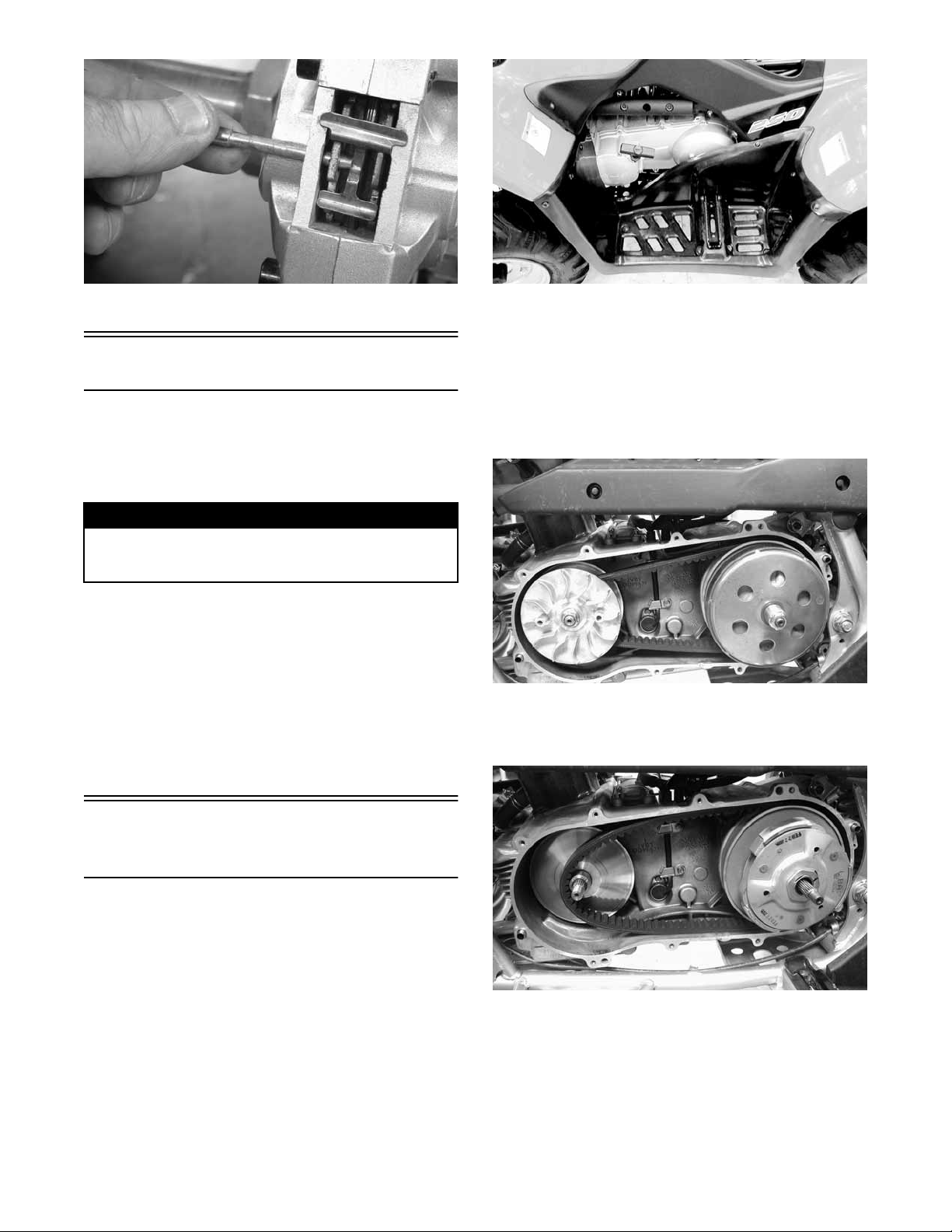
3. Remove the cap screws securing the V-belt cover
noting the location of the different-lengthed cap
screws for installing purposes; then using a rubber
mallet, gently tap on the cover tabs to loosen the
cover. Remove the cover. Account for two alignment
pins and one gasket.
KM253
4. Remove the nut securing the movable drive face;
then remove the face. Account for the stepped
washer and spacer.
Checking/Replacing
V-Belt
REMOVING
1. On the Utility, remove the left footwell; then remove
the recoil starter assembly. On the DVX, proceed to
step 2.
18
KM276
5. Remove the nut securing the driven pulley; then
remove the splined bushing, centrifugal clutch, pulley, and V-belt.
INSTALLING
1. Using a rubber mallet, spread the driven pulley
sheaves by driving the V-belt down between the
sheaves; then slide the driven pulley and V-belt into
position.
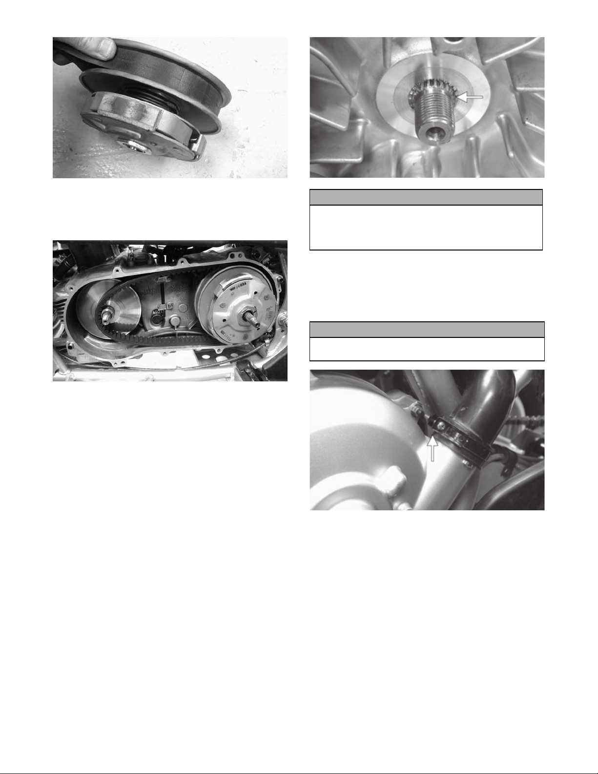
KM262
2. Install the centrifugal clutch housing onto the driven
shaft; then install the splined bushing and secure
with the driven pulley retaining nut. Tighten to 40 ftlb.
KM276
3. Install the movable drive face onto the crankshaft
making sure to “bottom” the sheave out against the
center bushing. The crankshaft splines should be visible and the stepped washer should sit over the
splines.
KM263A
CAUTION
If the splines are not protruding as shown, the V-belt
may be too deep in the drive sheaves. This would cause
the drive pulley to be under-tightened and severe drive
sheave or crankshaft damage could occur.
4. Secure the movable drive face to the crankshaft with
the drive pulley nut and tighten to 72 ft-lb.
5. Install the V-belt cover and tighten the cap screws
securely; then connect the cooling boots and tighten
the clamps securely.
CAUTION
On the DVX, the rear boot clamp must be oriented as
shown or interference with heat shielding could occur.
KM252A
6. Install the recoil starter and footwell assembly (Utility). Tighten all hardware securely.
19
Steering/Frame/Controls
The following steering components should be inspected
periodically to ensure safe and proper operation.
A. Handlebar grips not worn, broken, or loose.
B. Handlebar not bent or cracked and has equal and
complete full-left and full-right capability.
C. Steering post bearing assembly/bearing housing
not broken, worn, or binding.
D. Ball joints not worn, cracked, or damaged.
E. Tie rods not bent or cracked.
F. Knuckles not worn, cracked, or damaged.
G. Cotter pins not damaged or missing.
The frame, welds, and racks should be checked periodically for damage, bends, cracks, deterioration, broken
components, and missing components.
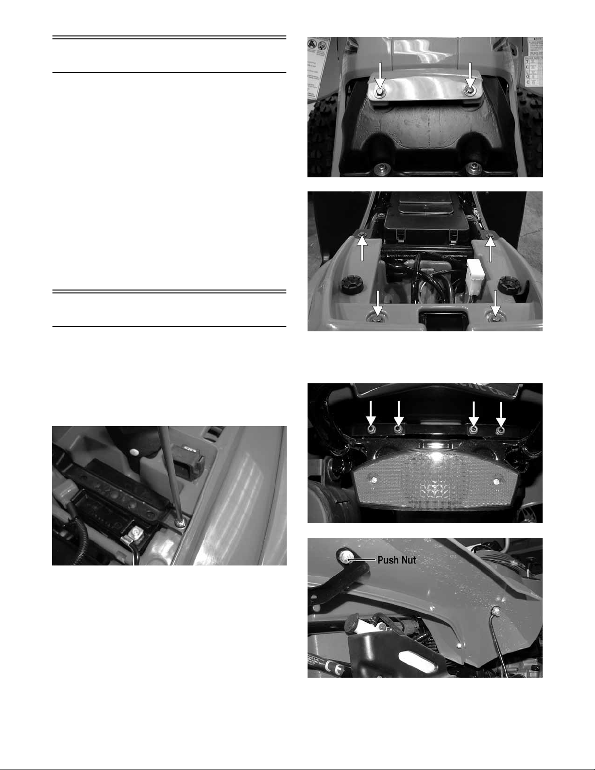
Body
REMOVING (DVX)
1. Remove the seat; then remove the battery hold-down
strap, battery, and starter relay. Lay the relay aside
without disconnecting the wiring.
KM782A
KM790A
4. Remove four flange nuts and cap screws securing the
rear fender support; then remove the push nuts from
the mounting studs at the front of the rear fenders.
NOTE: Always remove the negative battery cable
first; then the positive cable.
SP107
2. Remove the CDI, start-in-gear relay, and fuse block
and lay aside without disconnecting the wires; then
remove the shift knob.
3. Remove the six cap screws securing the body to the
top of the frame; then remove the cap screws from
the bottom of the battery box.
KM785A
20
KM784A
5. Remove the hardware securing the front fenders to
the fender supports; then disconnect the headlight.
KM352A
6. Turn the handlebar to the left; then raise the body
turning it to the right and lift clear of the handlebar.
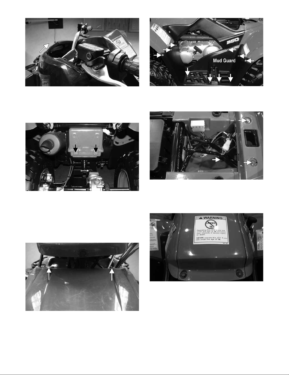
REMOVING (Utility)
1. Remove the seat; then remove the battery box cover.
KM793A
2. Disconnect the negative battery cable first; then the
positive cable.
3. Remove the battery hold-down strap; then remove
the battery.
KM789A
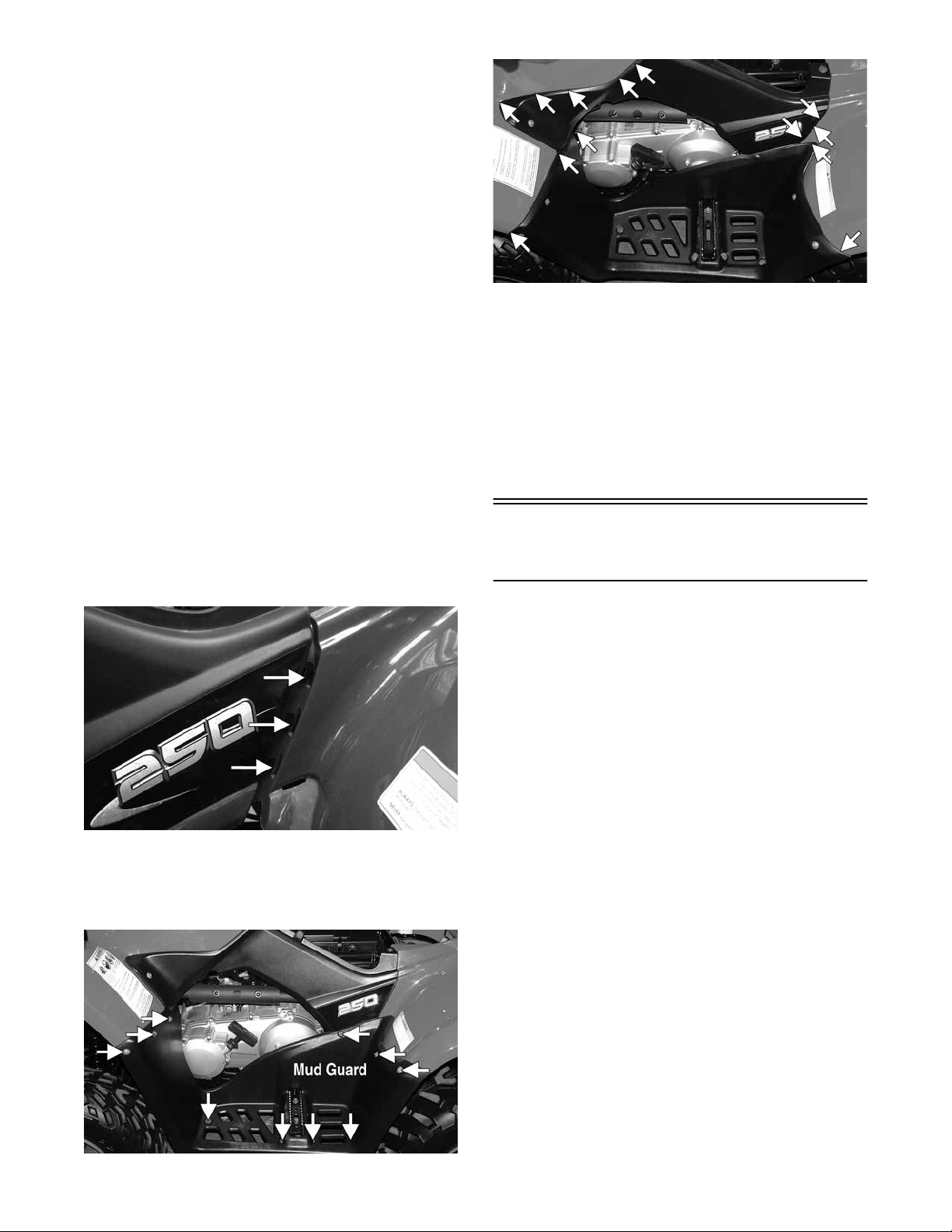
6. Remove the side panels; then remove the cap screws
and flange nuts securing the front and rear fenders to
the frame and fender supports.
KM799B
7. Disconnect the left and right headlight connectors;
then disconnect the taillight.
8. Remove the gas tank cover; then remove the shift
knob and front and rear fenders.
4. Remove the front and rear racks; then remove the
cap screws securing the front center panel and
remove the panel.
KM308A
5. Remove the cap screws and flange nuts securing the
mud guards to the front and rear fenders; then
remove the cap screws securing the mud guards to
the front rests and remove the mud guards.
KM797
CLEANING AND INSPECTING
1. Clean all body components with soap and water.
2. Inspect the body and fenders for cracks.
3. Inspect threaded areas of all mounting studs for stripping.
4. Inspect for missing decals.
INSTALLING (DVX)
1. Fit the body over the handlebar and rotate into normal mounting position.
21
2. Using the existing hardware, secure the front fenders
to the fender supports; then connect the headlight.
3. Using the existing hardware, secure the rear fenders
to the forward fender supports; then secure the rear
fender to the frame with four cap screws and flange
nuts. Tighten securely.
4. Install the six cap screws securing the body to the top
of the frame. Tighten securely.
5. Install the fuse block, start-in-gear relay, and the
CDI; then install the body mounting cap screw into
the bottom of the battery box.
6. Install the battery and battery hold-down strap; then
connect the positive battery cable and the negative
battery cable.
NOTE: Always install the positive cable first; then
install the negative cable.
7. Install the seat making sure it is latched securely.
INSTALLING (Utility)
1. Place the front and rear fenders into position on the
frame and secure with the existing hardware; then
install the gas tank cover. Tighten all fasteners
securely.
2. Connect the headlight and taillight connectors; then
install the shift knob.
3. Making sure the locating tabs engage the appropriate
slots in the fenders, install the side panels.
KM788A
5. Install the front center cover; then install the front
and rear racks. Tighten all fasteners securely.
6. Install the battery; then connect the positive battery
cable, negative battery cable, and battery hold-down
strap.
NOTE: Always install the positive cable first; then
install the negative cable.
7. Install the battery cover; then install the seat making
sure it locks securely in place.
Steering Post Cover/
Instrument Pod
REMOVING (DVX)
1. Remove the two reinstallable rivets on the rear of the
steering post cover; then lift up and push the assembly forward to remove.
2. Disconnect the wire connectors from the indicator
lights and from the ignition switch.
KM340A
4. Install the mud guards and secure to the fenders and
foot rest supports with the existing hardware. Make
sure all locating tabs are appropriately engaged with
the fenders and side panels.
KM789A
REMOVING (Utility)
1. Remove the reinstallable rivet on the front of the
instrument pod and the two cap screws on the rear;
then lift the assembly off and disconnect the speedometer cable.
2. Remove the self-tapping screw securing the LCD
gauge assembly to the instrument pod; then remove
the LCD gauge.
NOTE: The LCD gauge is not a serviceable compo-
nent. If any functions are incorrect or indicator lights
do not illuminate, the LCD gauge must be replaced.
INSPECTING/SERVICING (DVX)
1. Remove the two self-tapping screws securing the
indicator lamp assembly in the steering post cover.
2. Inspect the bulbs for blackening or burn out. Replace
as required.
3. Inspect the indicator lamp holder for loose sockets, broken wires, or loose connections. Replace as required.
22
INSPECTING (Utility)
The LCD gauge is not a serviceable component. To
inspect the LCD gauge, see Electrical System.
INSTALLING (DVX)
1. Connect the indicator lamp connectors; then connect
the main harness connector to the ignition switch.
2. Place the steering post cover onto the mounting
bracket; then secure with the reinstallable rivets.
INSTALLING (Utility)
1. Connect the main harness connector to the LCD
gauge; then connect the ignition harness to the ignition connectors.
2. Place the instrument pod onto the mounting bracket; then
secure with the reinstallable rivet and tw o cap screws.
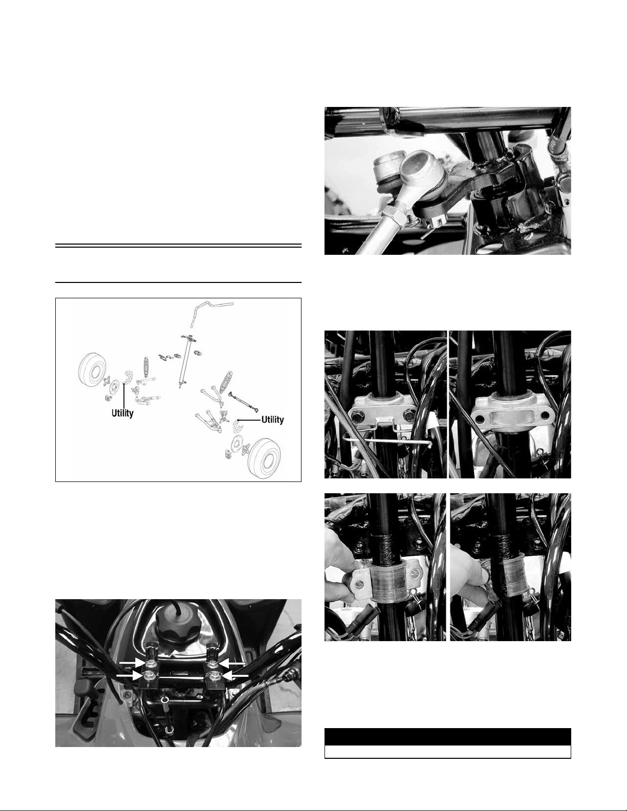
3. Lift the handlebar out of the lower handlebar holders
and lay the handlebar forward.
4. Remove the cotter pins and slotted nuts securing the
tie rod ends to the steering post arm; then disconnect
the tie rods from the arm.
Steering Post/Tie Rods
KM598E
REMOVING
1. On the Utility, remove the front rack and front center
panel. On the DVX, proceed to step 2.
2. Remove the steering post cover (DVX) or the instrument pod (Utility); then remove the cap screws
securing the handlebar to the steering post. Account
for two handlebar holders.
KM590
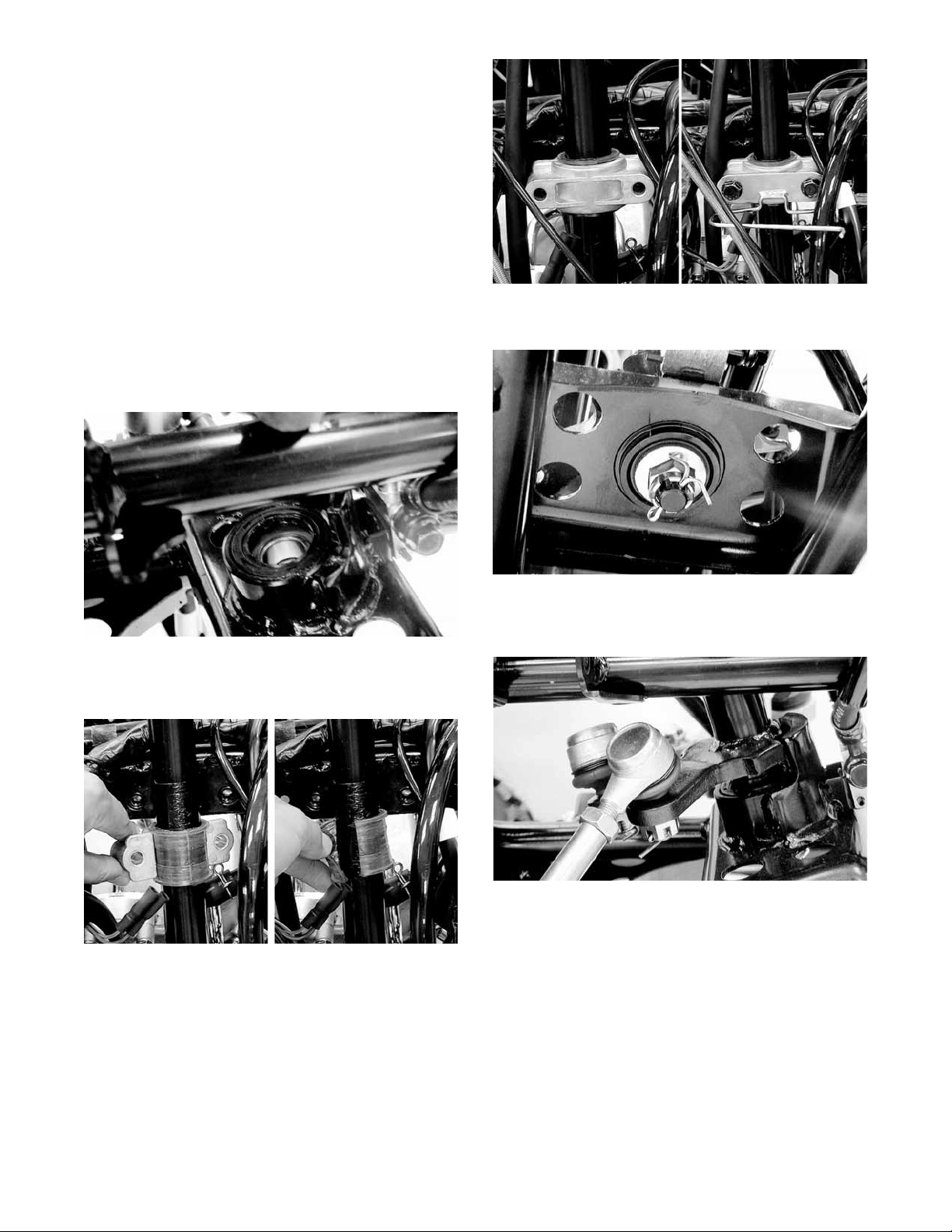
5. Remove the cotter pin and slotted nut from the lower
end of the steering post; then remove the upper steering shaft support block. Account for a cable guide,
two steering support blocks, and the upper steering
post bushing.
.
KM588
KM189A
KM589
6. Remove the steering post from the ATV.
CLEANING AND INSPECTING
1. Wash the tie rod ends in parts-cleaning solvent. Dry
with compressed air. Inspect the pivot area for wear.
Apply a low-temperature grease to the ends.
! WARNING
Always wear safety glasses when using compressed air.
23
2. Inspect the tie rods for damaged threads or wear.
3. Inspect the tie rods for cracks or unusual bends.
4. Inspect all welded areas for cracks or deterioration.
5. Inspect the steering post and steering-post holders
for cracks, bends, or wear.
6. Inspect the handlebar clamps for cracks or wear.
7. Inspect the handlebar for cracks, wear, or unusual
bends.
8. Inspect the handlebar grips for damage or wear.
9. Inspect the lower steering post support bearing and
seal for wear or cracks.
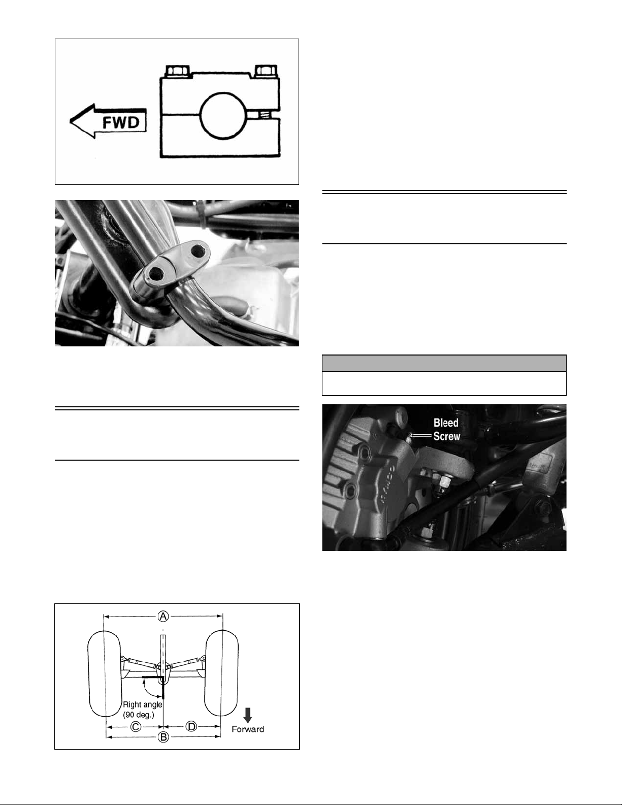
INSTALLING
1. Apply a thin coat of grease to the lips of the lower
steering post seals; then lower the steering post into
position in the lower steering post bearings.
KM593
2. Apply a thin coat of grease to the upper steering post
bushing; then secure the steering post with the support
blocks and existing hardware. Tighten to 17 ft-lb.
KM595
3. Install the slotted nut on the lower steering post and
tighten to 50 ft-lb; then install a new cotter pin.
KM591
4. Place the inner tie rod ends into the steering post arm
and tighten the slotted nuts to 15 ft-lb; then install
new cotter pins.
24
KM589
KM590
5. Install the handlebar and tighten the clamp cap
screws to 18 ft-lb making sure to tighten the front
cap screws first.
KM587
KM597
6. Install the instrument pod (Utility) or steering post
cover (DVX).
7. Install the center panel and front rack (Utility).
4. Adjust toe-in to 15 mm (0.60 in.); then measure distances (C) and (D). Distances (C) and (D) should be
equal.
5. After all the adjustments are to specifications,
tighten the tie-rod lock nuts to 15 ft-lb.
NOTE: Prior to locking the jam nuts, make sure the
ball joints are at the center of their normal range of
motion and at the correct angle.
NOTE: The front wheels do not have to be removed
to adjust the tie rod. Also, care should be taken not to
disturb the handlebar position.
Front Brake Lever/Master
Cylinder Assembly
NOTE: The master cylinder is a non-serviceable
component; it must be replaced as an assembly.
REMOVING
1. Connect a clear hose to the bleed screw on either
front brake caliper; then open the bleed screw and
pump the brake fluid into a suitable container. Close
the bleed screw.
CAUTION
Brake fluid is highly corrosive. Do not spill brake fluid
on any surface of the ATV.
Measuring/Adjusting
Toe-In/Toe-Out
1. With the ATV on a level surface, center the handlebar for straight ahead using a suitable means of measuring centering; then adjust tire pressure to
specifications (see General Information - General
Specifications).
2. Support the front of the ATV with the wheels free to
rotate; then center and secure the handlebar.
3. Measure the distance (A) and (B) between the front
wheels; then subtract distance (B) from (A). Distance
A - Distance B = Toe-In.
KM116A
NOTE: Do not reuse brake fluid. When exposed to
air, brake fluid rapidly absorbs moisture.
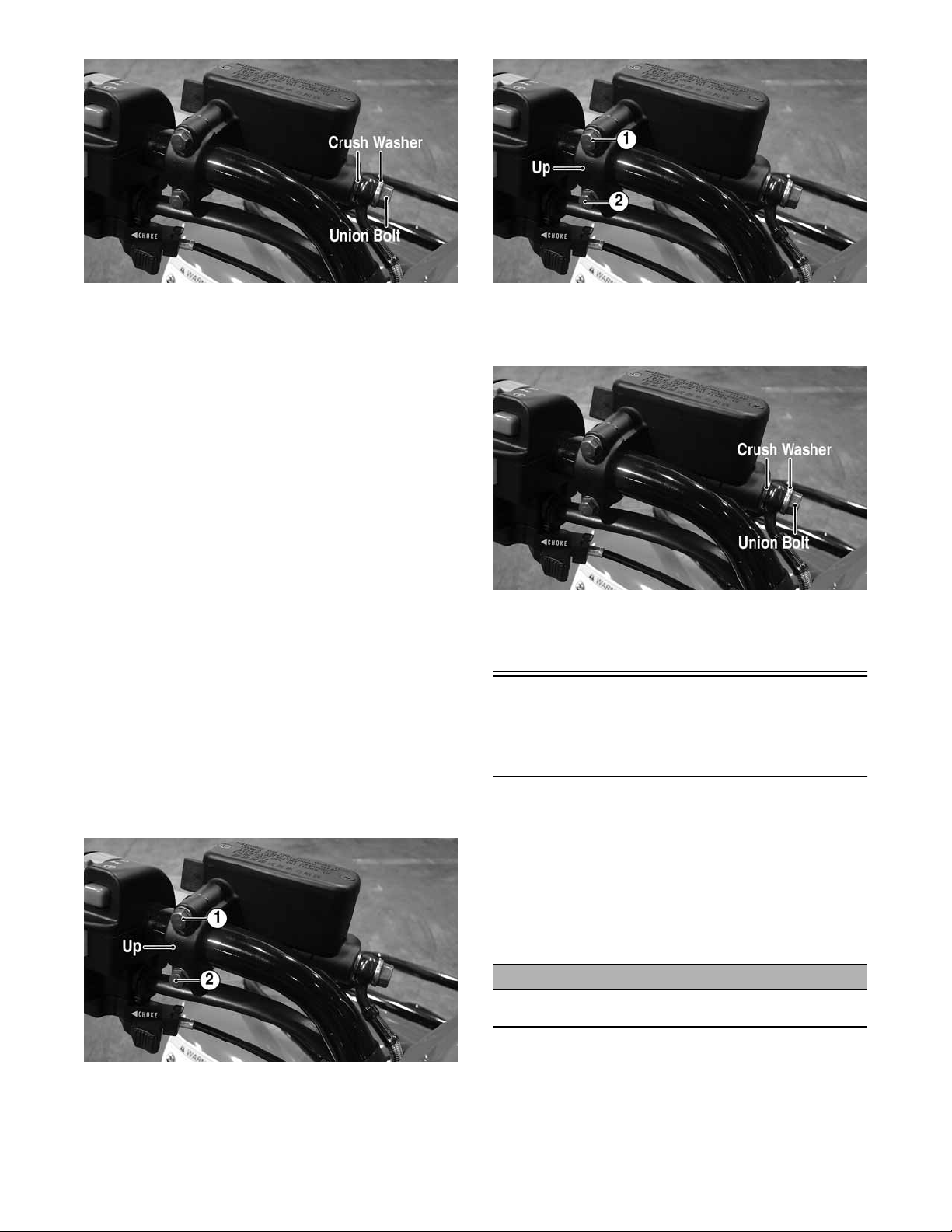
2. Remove the brakeline hose union bolt; then remove
the cap screws securing the master cylinder assembly
to the handlebar. Discard the crush washers from the
union bolt.
ATV2205
25
KM800A
3. Remove the brake lever, brakelight switch, and brake
lever lock.
INSPECTING
1. Inspect the pivot bolt securing the brake lever for
wear.
2. Inspect the brake lever for elongation of the pivot
hole.
3. Inspect the reservoir for cracks and leakage.
4. Inspect the brake hose for cracks and deterioration
and the condition of the fittings (threaded and compression).
5. Inspect the brakelight switch for corrosion, cracks,
missing or broken mounting tabs, or broken and
frayed wiring.
NOTE: If the brakelight switch is determined to be
not serviceable, see Electrical System - Taillight Brakelight.
INSTALLING
1. Install the brakelight switch on the master cylinder;
then install the brake lever and brake lever lock.
2. Install the master cylinder assembly on the handlebar
engaging the alignment stud in the hole in the handlebar; then secure with the master cylinder clamp
and two cap screws. Make sure the UP arrow on the
clamp is directed upward.
KM800B
4. Using new crush washers, secure the brake hose to
the master cylinder with the brake hose union bolt.
Tighten to 25 ft-lb.
KM800A
5. Fill the master cylinder with DOT 4 brake fluid; then
bleed the system (see Periodic Maintenance Hydraulic Brake Systems).
Auxiliary Brake Pedal/
Master Cylinder
Assembly
NOTE: The auxiliary brake master cylinder is a non-
serviceable component; it must be replaced as an
assembly.
KM800B
3. Tighten the cap screw (1) to 13 ft-lb; then tighten the
cap screw (2) to 13 ft-lb.
26
REMOVING
1. Connect a clear plastic hose to the appropriate bleed
screw on the rear brake caliper; then loosen the bleed
screw and pump the foot brake until the fluid is
pumped into a suitable container.
CAUTION
Brake fluid is highly corrosive. Do not spill brake fluid
on any surface of the ATV.
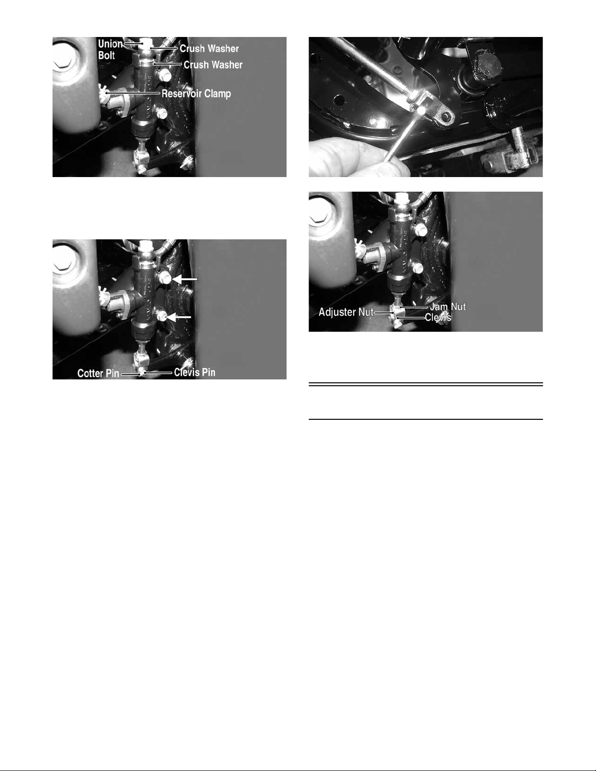
2. Compress the reservoir clamp and remove the reservoir hose; then remove the union bolt. Account for
and discard two crush washers.
KM801A
3. Remove the cotter pin from the clevis pin and
remove the clevis pin; then remove the two cap
screws securing the master cylinder to the frame and
remove the master cylinder.
KM801B
4. Loosen the jam nut; then remove the clevis and
adjuster nut.
INSTALLING
1. Install the jam nut; then install the clevis and adjuster
nut. Finger-tighten only at this time.
2. Secure the master cylinder to the frame with the two
cap screws and tighten securely.
3. Using two new crush washers, connect the brake
hose to the master cylinder with the union bolt; then
making sure the spring clamp is seated securely, connect the reservoir hose to the master cylinder.
Tighten the union bolt to 25 ft-lb.
4. Making sure the brake pedal is fully released and
against the stop, turn the clevis and adjuster nut until
the hole in the clevis is aligned with the hole in the
brake pedal lever; then tighten the jam nut securely.
CD476
KM801C
5. Fill the master cylinder reservoir with DOT 4 brake
fluid and bleed the system (see Periodic Maintenance/Tune-Up - Hydraulic Brake Systems).
Throttle Control
REMOVING
1. Remove the boot from the throttle cable adjuster;
then loosen the jam nut and turn the adjuster completely in to loosen the cable.
2. Remove the three machine screws securing the cover
to the throttle control; then remove the cover and disengage the throttle cable from the throttle arm.
3. Turn the cable adjuster out of the throttle control
housing; then remove the two machine screws securing the throttle control to the handlebar and remove
the throttle control.
INSTALLING
1. Making sure the throttle housing upper flat aligns
with the alignment mark on the handlebar, place the
throttle control into position on the handlebar and
secure with the two machine screws; then tighten the
machine screws securely.
27
 Loading...