

Page 1
NOsparc® User Manual
MGXDC1F250
This product is manufactured under the following patents: US 9,087,653, US 8,619,395, US 9,423,442, and other
patents pending.
Contact Arc Suppressor for DC Power
Relays, Contactors, and Micro-Switches
IMPORTANT NOTES
This document provides information required to install a NOsparc arc suppressor.
You must read and understand this document before installing this device.
© 2016 Arc Suppression Technologies. All rights reserved.
104-0045B
If you have any trouble with your installation, please refer to Technical Support contact information below.
Full Terms & Conditions and Warranty Available at: www.ArcSuppressionTechnologies.com
CONTACT INFORMATION
Arc Suppression Technologies, 7900 International Drive, Suite 300, Bloomington, MN 55425-2562 USA
+1 (612) 928-5269 // [email protected] // www.ArcSuppressionTechnologies.com
TABLE OF CONTENTS
IMPORTANT NOTES .............................................. 1
TRADEMARKS .................................................................. 1
APPLICABLE DOCUMENTS ............................................. 1
PART NUMBER & PRODUCT DESCRIPTION ................... 1
LIFE SUPPORT .................................................................. 2
LEGAL NOTICE ................................................................ 2
SAFETY INFORMATION OVERVIEW ...................... 2
WARNINGS ...................................................................... 2
SAFETY ............................................................................. 2
CAUTIONS ....................................................................... 3
NOTES .............................................................................. 3
DISCLAIMER .......................................................... 3
MATERIAL CATEGORY POLICY ............................. 3
WARRANTY ........................................................... 3
TECHNICAL SUPPORT ........................................... 3
CONDITIONS FOR SERVICE ............................................ 3
RETURN MATERIAL AUTHORIZATION & PROCESS ....... 4
CASE SPECIFICATIONS AN MOUNTING ............... 4
CASE DIMENSIONS ......................................................... 4
3-PHASE CONFIGURATION DIMENSIONS ..................... 4
DIN RAIL MOUNTING ...................................................... 4
PRODUCT DESCRIPTION ....................................... 4
DEFINITIONS ......................................................... 4
SPECIFICATIONS ................................................... 5
CIRCUIT BREAKER / CIRCUIT FUSE DE-RATINGS ........... 6
SYSTEM WIRING .................................................... 6
TRADEMARKS
“NOsparc” and the “flame” logo are registered trademarks
of Arc Suppression Technologies. All other trademarks are
property of their respective owners.
APPLICABLE DOCUMENTS
The UL Recognized Component mark
shown at right indicates that UL LLC has
certified the compliance of the NOsparc
units included in this manual as “Component - Auxiliary
Devices” for both Canada and the United States, per UL 508
Industrial Control Equipment and CSA-C22.2 No. 14, Industrial
Control Equipment.
PART NUMBER & PRODUCT DESCRIPTION
Example shown: NOsparc MGXDC1F250
File No.: E346457
Page 2

Page 2 of 6 ! NOsparc User Manual
Arc Suppression Technologies www.ArcSuppressionTechnologies.com
LIFE SUPPORT
Arc Suppression Technologies products are specifically NOT
authorized for use as critical components in life support
devices or systems without the express written approval of the
Chief Executive Officer of Arc Suppression Technologies.
As used herein:
Life support devices or systems are devices or systems which
support or sustain life and whose failure to perform when
properly used in accordance with instructions for use
provided in the labeling can be reasonably expected to
result in significant injury to the user.
A critical component is any component in a life support
device or system whose failure to perform can be reasonably
expected to cause the failure of the life support device or to
affect its safety or effectiveness.
LEGAL NOTICE
Information in this document is believed to be accurate and
is provided solely in connection with Arc Suppression
Technologies products.
Arc Suppression Technologies makes no warranties,
expressed or implied, regarding the information contained
herein.
Arc Suppression Technologies assumes no liability for errors
and omissions that may occur in this document.
Arc Suppression Technologies reserves the right to make
changes, corrections, modifications or improvements, to this
document and the product described herein at any time,
without notice.
This product is sold pursuant to Arc Suppression
Technologies’ terms and conditions of sale. This product is
resold under the terms and conditions of distributors,
representatives, and value-added resellers
Arc Suppression Technologies assumes no liability otherwise
arising from the application or use of any such information or
product for any infringement of patents or other intellectual
property rights owned by others, which may result from such
application, or use.
Purchasers are solely responsible for the choice, selection
and use of the product described herein, and Arc
Suppression Technologies assumes no liability whatsoever
relating to the choice, selection or use of this product.
No license, expressed or implied, by estoppel or otherwise,
to any intellectual property rights is granted under this
document. If any part of this document refers to any third
party products or services it shall not be deemed a license
grant by Arc Suppression Technologies for the use of such
third party products or services, or any intellectual property
contained herein or considered as a warranty covering the
use in any manner whatsoever of such third party products or
services or any intellectual property contained therein.
Arc Suppression Technologies only accepts products for
repair or return that are accompanied by a Return Material
Authorization number from either our company or the
appropriate distributor or sales representative.
Please refer to your original purchase agreement or contact
your distributor or sales representative for return policy
information.
SAFETY INFORMATION OVERVIEW
We use note, caution and warning symbols throughout this
book to draw your attention to important operational and
safety information.
“WARNING” describes an alert with information that
is
important for protecting personnel and equipment from
damage.
“CAUTION” describes any condition that could result in
damage to the equipment or result in physical
harm to personnel.
The CAUTION or WARNING “SAFETY” alert
symbol (an exclamation mark in a triangle) precedes a
general caution or warning statement. It describes safety
requirements to meet local, national and international
standards.
The Electrical Shock Hazard CAUTION OR
WARNING symbol, (a lightning bolt in a triangle)
precedes an electric shock hazard. It describes a
potential electrical shock hazard which can result in personal
injury or death.
“NOTE” describes any item of interest to the user, owner, or
operator.
WARNINGS
Disconnect all power to circuits and panels where
this product is about to be installed or when
installing this product.
Follow extreme caution when applying NOsparc
to trip and close contacts or in circuits containing
elements that can be energized by a 1/2 power
cycle pulse.
This User Manual must be thoroughly understood and
accurately followed to avoid unintended equipment operation.
The assembly must conform to National Electric
Code (NEC) safety standards, as well as locally
applicable codes. Failure to do so could result in
personal injury or loss of life. See the product
rating curve for wire gauge selection, ambient
temperature and current restrictions.
Follow extreme caution when conducting short
cycle time tests, especially below the maximum
rated cycle time for the associated relay; typically
3s. Even at significantly reduced power levels the relay
contacts become extremely hot due to high current
densities at the point of contact constriction just before the
contact breaks open. Always follow the relay manufacturers
specifications and requirements. Standard relays typically
have a maximum short period cycle time of 1200 cycles per
hour.
Only authorized and qualified personnel should
install and service the NOsparc MGXDC1F.
Failure to comply with these recommendations
may result in damage to equipment and property and injury
to personnel.
Always test the function and performance of NOsparc in the
intended application.
An arc suppressor DOES NOT eliminate arcing,
therefore, NOsparc will not eliminate hazards
associated with electrical current contact arcing.
SAFETY
All creepage distances and clearances of NOsparc have
been designed to meet requirements of safety standards.
When using NOsparc MGXDC1F, basic safety precautions
should always be followed to reduce risk of fire, electric
shock, and injury to persons. When installing NOsparc into
your system, make sure that the Quick Connect Terminal
connector is properly crimped, terminated, insulated and that
the proper wire gauge is used and that the connector is
securely seated. Incorrect application or termination can result
in harmful or fatal electrical shock or component damage.
Page 3

NOsparc User Manual ! Page 3 of 6
www.ArcSuppressionTechnologies.com Arc Suppression Technologies
– Inductive
– Motor
–
Tungsten
–
Pulse width modulated (PWM)
– Variable Frequency Drive (VFD)
– Safety interlocks
– Thermal limits
CAUTIONS
The NOsparc will pass a leakage current (see specifications)
even though the contacts across which it is connected are
open (similar to leakage present with snubber use). This
capacitive leakage current can be sufficient to turn-on some
solid state and electromechanical relays, or to cause electric
shock to personnel. Therefore:
– The NOsparc must never be connected across relay,
contactor, or snap action switch contacts driving high
impedance loads.
– The NOsparc must never be connected across relay,
contactor, or snap action switch contacts used for
galvanic/safety isolation.
Proper care must be taken when handling and installing
NOsparc MGXDC1F.
Never plug or unplug NOsparc while powered.
Do not connect NOsparc directly to power!
Use caution when installing or modifying power connections.
NOTES
Connect NOsparc across the power switching relay,
contactor, or snap action switch contacts only!
NOsparc capabilities will be fully effective even under mixed
load conditions.
NOsparc has been designed to support the following DC
power loads:
– General purpose
– Resistive
– Capacitive
DO NOT use NOsparc DC power products for AC power
applications.
DO NOT use NOsparc on the following power circuits:
– Non-sinusoidal
– Phase controlled
DO NOT connect NOsparc across the following
components:
– Fuses
– Circuit breakers
DO NOT use NOsparc either above or below its ratings or
specifications.
DO NOT operate the contacts to which the NOsparc is
attached above or below their ratings or specifications.
DISCLAIMER
All product, product specifications and data are subject to
change without notice to improve reliability, function or
design or otherwise.
Arc Suppression Technologies, LLC, its affiliates, agents, and
employees, and all persons acting on its or their behalf
(collectively, “Arc Suppression Technologies”), disclaim any
and all liability for any errors, inaccuracies, or incompleteness
contained in this User Manual or in any other disclosure
relating to any product.
Arc suppression Technologies makes no warranty,
representation or guarantee regarding the suitability of the
products for any particular purpose or the continuing
production of any product. To the maximum extent permitted
by applicable law, Arc Suppression Technologies disclaims (i)
any and all liability arising out of the application or use of any
product, (ii) any and all liability, including without limitation
special, consequential or incidental damages, and (iii) any and
all implied warranties, including warranties of fitness for
particular purpose, non-infringement and merchantability.
Statements regarding the suitability of products for certain
types of applications are based on Arc Suppression
Technologies’ knowledge of typical requirements that are
often placed on Arc Suppression Technologies products in
generic applications. Such statements are not binding
statements about the suitability of products for a particular
application. It is the customer’s responsibility to validate that a
particular product with the properties described in the
product specification is suitable for use in a particular
application. Parameters provided in data sheets and/or
specifications may vary in different applications and
performance may vary over time. All operating parameters,
including typical parameters, must be validated for each
customer application by the customer’s technical experts.
Product specifications do not expand or otherwise modify Arc
Suppression Technologies’ terms and conditions of purchase,
including but not limited to the warranty expressed therein.
Except as expressly indicated in writing, Arc Suppression
Technologies products are not designed for use in medical,
life-saving, or life-sustaining applications or for any other
application in which the failure of the Arc Suppression
Technologies product could result in personal injury or death.
Customers using or selling Arc Suppression Technologies
products not expressly indicated for use in such applications
do so at their own risk.
MATERIAL CATEGORY POLICY
Arc Suppression Technologies, LLC hereby certifies that all
its products that are identified as RoHS-Compliant fulfill the
definitions and restrictions defined under Directive
2011/65/EU of The European Parliament and of the Council
of June 8, 2011 on the restriction of the use of certain
hazardous substances in electrical and electronic equipment
(EEE) - recast, unless otherwise specified as non-compliant.
WARRANTY
NOsparc arc suppressors are manufactured to high quality
standards and backed by a warranty that is included in our
Terms and Conditions of Sale that can be found at our
website:
http://www.arcsuppressiontechnologies.com/where-tobuy/terms-and-conditions-of-sale/
TECHNICAL SUPPORT
Please contact your distributor or sales representative with
technical support and product support questions. Have the
NOsparc model number available when contacting your
representative.
In certain circumstances, direct product support from Arc
Suppression Technologies may be reached via the following
communication methods:
www.arcsuppressiontechnologies.com/contact-us/support/
Phone +1 (612) 928-5546
CONDITIONS FOR SERVICE
In the event of a product malfunction, Arc Suppression
Technologies or an authorized agent should perform all
repairs to a NOsparc arc suppressor. It is the responsibility of
users requiring service to report the need for service to their
distributor or sales representative.
Any components, devices or other equipment used with or
adjacent to a NOsparc arc suppressor is the sole responsibility
of the end user and not of Arc Suppression Technologies or
any of its agents, resellers, representatives or distributors.
Page 4
Page 4 of 6 ! NOsparc User Manual
Arc Suppression Technologies www.ArcSuppressionTechnologies.com
RETURN MATERIAL AUTHORIZATION & PROCESS
1. Authorization prior to returning product is required.
Please refer to your original purchase agreement or
contact your distributor or sales representative for an
RMA number and instructions before returning product.
2. After we receive your return, we will examine it and try to
verify the reason for returning it.
3. In cases of manufacturing defect, we will enter a
replacement order or issue credit for product returned. In
cases of customer misuse, we will request a purchase
order to provide replacement product.
4. To return products that are not defective, goods must be
in new condition, in the original boxes and they must be
returned within 120 days of receipt. A 20 percent
restocking charge is applied for all returned stock.
5. Arc Suppression Technologies reserves the right to
charge for no trouble found (NTF) returns.
CASE SPECIFICATIONS AND MOUNTING
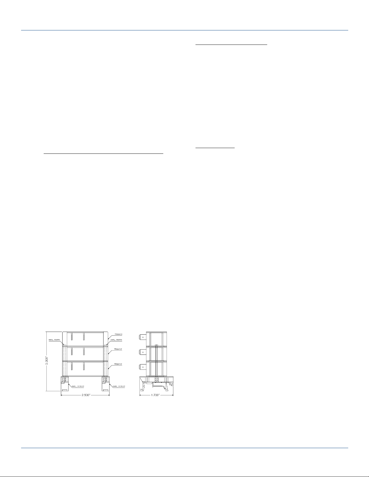
CASE DIMENSIONS
DIN RAIL MOUNTING
DIN rail mounting of one (1), two (2), or three (3) stacked arc
suppressors can be accomplished by
adding a single DIN rail mounting
adaptor (NOT PROVIDED) (accepting
up to a 1¾ inch #6 screw) to each side
of the single arc suppressor or stacked
arc suppressors.
Note: The above images are a representation only. DIN
Mounting Clips are available from a variety of suppliers.
(One example of an appropriate plastic DIN Rail Mounting
Clip is available from Digikey with the part number: 2772296-ND).
PRODUCT DESCRIPTION
The NOsparc MGXDC1F250 (DC power applications) is a
two-terminal contact arc suppressor that attaches across the
contact points of a power relay, contactor, or snap action
switch. The product is designed to protect the contact
points from premature destruction due to contact current
arcing. This extends contact life 10X or more depending on
application.
In simple terms, NOsparc operates as follows:
1. NOsparc detects the occurrence of an arc event.
2. NOsparc activates to suppress the arc.
3. NOsparc deactivates when the contacts are open and
suppression is not required.
4. NOsparc is continuously protected by over-voltage
suppression.
DEFINITIONS
Arc Current ............. Plasma flow supported between open
contacts
Arc Suppression
Duration .................. Time during which the electrical current
contact arc is arrested
Arc Suppressor ...... Device designed to reduce contact
arcing
Break ....................... Action of a contact which transitions
from close to open
Bounce .................... One or more brief transition(s) to the
OPEN state as the contact is closing or
to the CLOSE state as the contact is
opening
Break Current ......... Contact current during Break
Cycle Time ............. Time between successive ON or OFF
contact states
Inductive Load ....... Motor or transformer form the main part
of the load
Inrush Current ........ Resulting turn-on current when
powering an inductive, capacitive or
tungsten load
Inrush Current
Limiter ..................... Device intended to limit the amount of
turn-on current when powering an
inductive, capacitive or tungsten load
Make ....................... Action of a contact which transitions
from open to close
Make Current ......... Contact current during Make
MOV ........................ Metal Oxide Varistor
MTBF ...................... Mean-Time-Between-Failures
Power-On
Passthrough ........... Current passing through the arc
suppressor during initial power-up
RC Snubber ............ Device with resistor and capacitor in
series across contact
Snubber .................. Device designed to limit voltage rise
times
Suppression ............ Action of minimization of undesired
event
Varistor Clamping
Voltage ................... Voltage at which steady state current
through the arc suppressor is ≥ 1mA
Maximum Varistor
DC Voltage ............. Maximum allowed voltage across the
arc suppressor (NOT operating voltage)
|
Page 5
NOsparc User Manual ! Page 5 of 6
www.ArcSuppressionTechnologies.com Arc Suppression Technologies
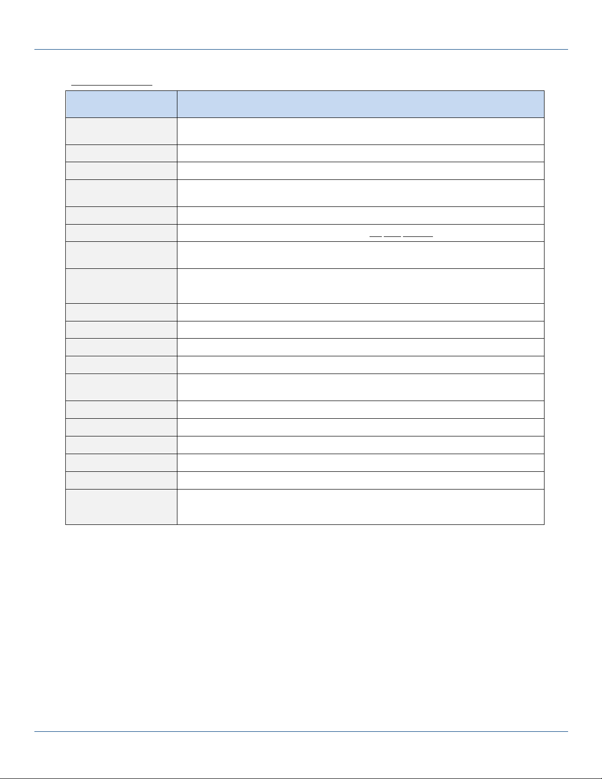
SPECIFICATIONS
NOsparc Model
MGXDC1F250
ABSOLUTE MAXIMUM
CURRENT RATING
75A. This absolute maximum current rating also represents the maximum allowable Locked Rotor
Amperage (LRA) for motor loads and the cold filament inrush current for tungsten loads
ARC SUPPRESSION
Duration: 1ms (typical)
CIRCUITS (CONTACTS)
One (1) NOsparc per contact (multiple NOsparc units required for multi-contact relays)
CIRCUIT BREAKER / FUSE
(MAXIMUM)
50A for resistive loads (see Safe Operating Area charts next page for more detail)
CLAMPING VOLTAGE
330V (typical at 1mA)
CONTACT CYCLING
Maximum cycle time: per relay specifications (DO NOT EXCEED relay operating specs)
DIMENSIONS
single: length: 2.380in (6.045cm) x width: 1.070in (2.718cm) x height: 0.740in (1.880cm)
ENVIRONMENTAL
operating temperature: -40°C to 85°C (-40°F to 185°F)
storage temperature: -50°C to 125°C (-58°F to 257°F)
humidity: 5% to 95% (non-condensing)
INTERFACE WIRES
across contacts: two (2) (W1 / W2 non-polarized)
LEAKAGE CURRENT
0.5mA (nominal)
MOUNTING
orientation: any // number of holes: two (2) // hole diameter: 0.150in (#6 screw) (3.81mm)
MTBF / RELIABILITY
2.6 million hours (MIL-HDBK-217F)
OPERATING VOLTAGE
(NOMINAL +/-15%)
12Vdc to 250Vdc
POWER-ON
load current passthrough: 1 ms
POWER TYPE
DC (direct current)
TERMINATION
0.250in quick connect male terminals (non-insulated)
TERMINATION MATE
0.250in quick connect female terminals (fully insulated)
WEIGHT
net weight: 1oz (28g)
WIRE GAUGE
wire length between Nosparc and contact terminals: 0in to 24in: #14AWG (minimum)
24in to 36in: #12AWG (minimum)
NOTE: wire lengths over 3 feet are NOT recommended
CIRCUIT BREAKER / CIRCUIT FUSE DE-RATINGS
The following charts depict the circuit breaker / circuit fuse Safe Operating Area (SOA) for different loads.
Page 6
Page 6 of 6 ! NOsparc User Manual
Arc Suppression Technologies www.ArcSuppressionTechnologies.com
SYSTEM WIRING
Each NOsparc arc suppressor has two male quick connect
terminals which must mate with two properly crimped
female quick connect terminals.
In order to provide effective arc suppression, the two wires
between NOsparc arc suppressor and the relay, contactor,
or snap action switch contact terminals should be as short as
possible.
One foot or less of wire length is ideal; lengths over 3 feet
are not recommended. If longer cable lengths are needed,
then the wire gauge must be increased according to the
following recommendation based on the length of wire
between NOsparc arc suppressor terminals and the contact
terminals:
#14AWG (minimum) for less than 24in of wire
#12AWG (minimum) for 24in to 36in of wire
Above: Proper NOsparc wiring across CONTACT.
NOsparc Wiring Diagram
Above: For simplicity, only a single (one) phase shown
Above, left to right: IMPROPER NOsparc wiring across LOAD,
across POWER, and across COIL.
CONTACT INFORMATION
ARC SUPPRESSION TECHNOLOGIES
7900 INTERNATIONAL DR STE 300, BLOOMINGTON MN 55425 USA
+1 (612) 928-5269 // [email protected]
www.ArcSuppressionTechnologies.com
IMPORTANT NOTE: Install NOsparc across the contact. DO NOT install NOsparc across the LOAD, POWER, OR COIL.
NOsparc will be damaged if connected across the following locations where there is NO arcing: LOAD, POWER, and/or COIL.
 Loading...