

ARCO ASKO Le12, ST.MORITZ Le10, ASKO Le08, ST.MORITZ Le06, ASKO Le10 Installation Manual
...Page 1
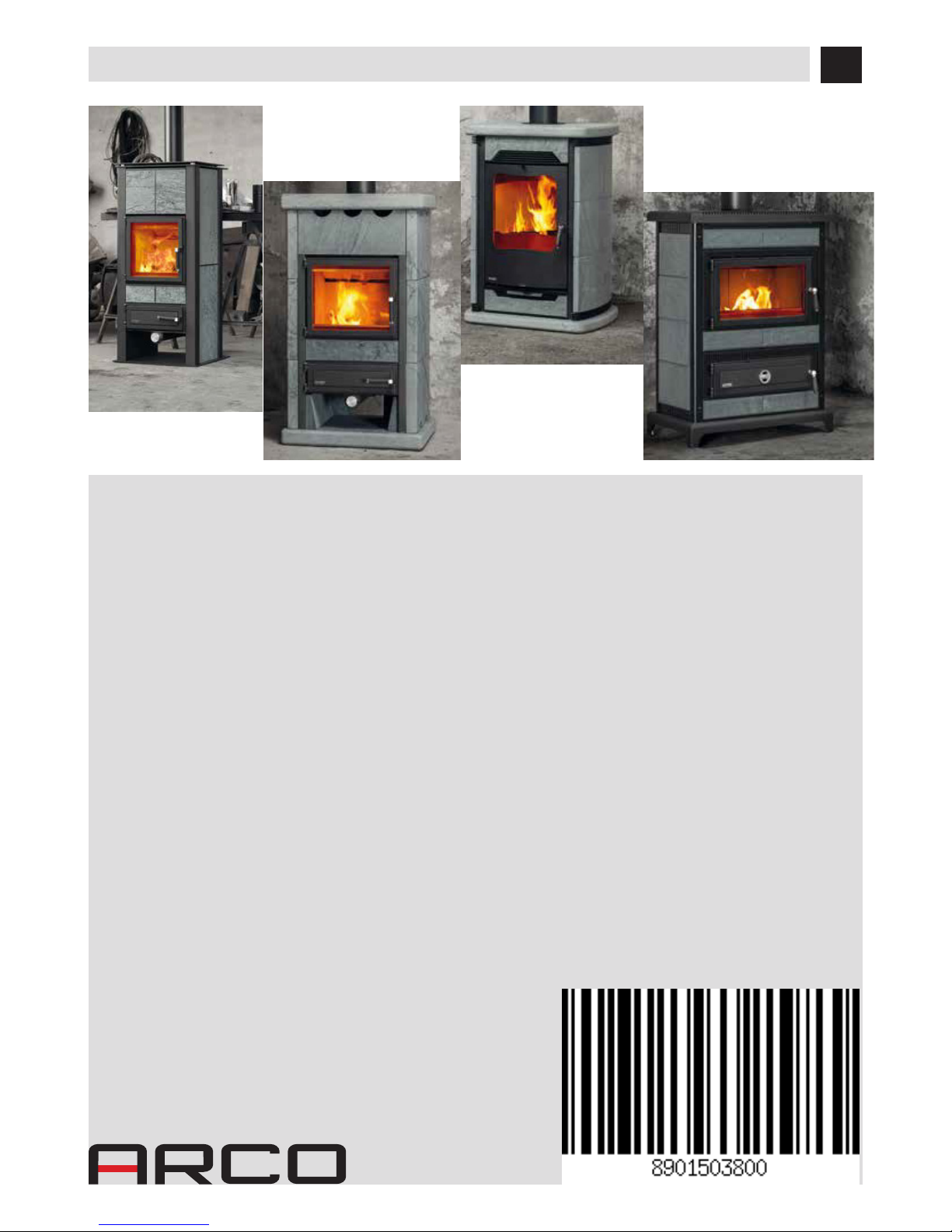
WOOD-BURNING STOVES
ASKO Le06 - Le08 - Le10 - Le12
ST.MORITZ Le06 - Le08 - Le10 - Le12
CHAMONIX Lf10 - Le11
CORTINA Le09 - Le10 - Lf11
INSTALLATION GUIDE EN
Translation of the original instructions
Page 2

II
TABLE OF CONTENTS
TABLE OF CONTENTS ....................................................................................... II
INTRODUCTION .............................................................................................. 1
1-WARNINGS AND WARRANTY CONDITIONS ........................................................ 2
2-INSTALLATION INSTRUCTIONS ....................................................................... 8
3-DIMENSIONS AND TECHNICAL FEATURES ........................................................19
4-DESCRIPTION OF PARTS ...............................................................................36
5-SERPENTINE STONES ASSEMBLY DIAGRAM ......................................................41
6-LIST OF PARTS AND OPERATION ....................................................................42
9-MAINTENANCE AND CLEANING ......................................................................44
Page 3
1
INTRODUCTION
Dear Customer,
our products are designed and manufactured in compliance with European reference Standards for construction products (EN13240
wood-burning stoves, EN14785 pellet-burning appliances, EN13229 replaces/wood-burning inserts, EN 12815 wood-burning cookers),
with high quality materials and extensive experience in the transformation processes.
To get the best performance, we suggest you read the instructions in this manual carefully.
This installation and use manual forms an integral part of the product: ensure that the manual is always supplied with the device, even if
the boiler changes owner. If the manual is lost, you can request another copy from the local technical service or download it directly from
the company website.
All local regulations, including those regarding national and European regulations, must be respected when the device is installed.
In Italy, for the installation of devices with biomass lower than 35KW, refer to ministerial decree 37/08, and the qualied installation technician with the appropriate requisites must issue a certicate of compliance for the system installed. (By system one means
Stove+Chimney+Air inlet).
REVISIONS TO THE PUBLICATION
The content of this manual is strictly technical and the property of CORRADI CUCINE S.r.l.
No part of this manual may be translated into other languages, adapted or reproduced, even in part, in other mechanical or electronic
forms, photocopies, recordings or other, without the prior written authorisation from CORRADI CUCINE S.r.l. The company reserves the
right to make changes to the product at any time without prior notice. The proprietary company reserves its rights according to the law.
CARE OF THE MANUAL AND HOW TO CONSULT IT
• Take care of this manual and keep it in an easily accessible place.
• Should the manual be misplaced or ruined, request a copy from your retailer or directly from the authorised Technical Assistance
Department. It can be downloaded from the company website.
• The "text in bold" must be read with particular care.
• The "text in italics" draws attention to other sections in this manual or clarications.
• “NOTE” provides the reader with additional information.
SYMBOLS USED IN THE MANUAL
ATTENTION:
Read the relative message with care as failure to observe the information provided could result in serious
damage to the product and put the persons who use it at risk.
INFORMATION:
failure to comply with these provisions will compromise the use of the product.
OPERATING SEQUENCES:
sequence of buttons to be pressed to access the menus or change settings.
MANUAL
carefully read this manual or the relative instructions.
Page 4

2
1-WARNINGS AND WARRANTY CONDITIONS
SAFETY PRECAUTIONS
• Installation, electrical connection, function test and maintenance
must only be carried out by authorised and qualied personnel.
• Install the product in accordance with all local and national legislation
and regulations in force in the region or state.
• Only use the fuel recommended by the manufacturer. The product must not be
used as an incinerator.
• It is strictly forbidden to use alcohol, petrol, liquid fuel for lanterns, diesel, bioethanol, uids for lighting charcoal or similar liquids to light/rekindle the ame
in these devices. Keep these ammable liquids well away from the appliance
when in use. Do not insert fuel other than wood in the combustion chamber.
• Do not insert fuel other than wood in the combustion chamber.
• The instructions provided in this manual must always be complied with to
ensure the product and any electronic appliances connected to it are used
correctly and accidents are prevented.
• This appliance can be used by children aged 8 years and above and
persons with reduced physical, sensory or mental capabilities or lack
of experience and knowledge if they have been given supervision
or instruction concerning use of the appliance in a safe way and
understand the hazards involved. Children must not play with the
appliance. Cleaning and user maintenance shall not be carried out by
children without supervision.
• The user, or whoever is operating the product, must read and fully understand
the contents of this installation guide before performing any operation. Errors
or incorrect settings can cause hazardous conditions and/or poor operation.
• Do not climb on or lean on the product.
• Do not put linen on the product to dry. Any drying racks or similar objects must
be kept at a safe distance from the product. Fire hazard.
• All liability for improper use of the product is entirely borne by the user and relieves
the Manufacturer from any civil and criminal liability.
Page 5

3
1-WARNINGS AND WARRANTY CONDITIONS
• Any type of tampering or unauthorised replacement with non-original spare
parts could be hazardous for the operator's safety and relieves the company
from any civil and criminal liability.
• Many of the surfaces of the product get very hot (door, handle, glass, smoke
extraction pipes, etc.). Avoid coming into contact with these parts
without adequate protective clothing or suitable means, such as
gloves with thermal protection or “cold handle” operating systems.
• It is forbidden to operate the product with the door open or the glass
broken.
• The doors/covers on the appliance must remain closed when it is not
used.
• The product must be powered by an electrical system that is equipped with an
eective earthing system.
• Do not wash the product with water.
• Do not stand for a long time in front of the product in operation. Do not overheat
the room you are in and where the product is installed. This could cause injuries
and health problems.
• Install the product in a location that does not present a re hazard and is
equipped with power and air supplies and smoke extractors.
• Do not use water to put the re out.
• In the event the chimney catches re never open the fuel loading door. Then
contact the competent authorities.
• The product and the cladding must be stored in a dry place and must not be
exposed to weathering.
Page 6

4
1-WARNINGS AND WARRANTY CONDITIONS
• It is recommended not to remove the feet that support the product in order to
guarantee adequate insulation, especially if the ooring is made of ammable
materials.
• Special maintenance must only be performed by authorised and qualied
personnel.
• Assess the static conditions of the surface on which the weight of the product
will rest and provide suitable insulation if it is made of ammable material (e.g.
wood, tted carpet or plastic).
Page 7

5
1-WARNINGS AND WARRANTY CONDITIONS
INFORMATION:
Please contact the retailer or qualied personnel authorised by the company to resolve a problem.
• You must only use the fuel specied by the manufacturer.
• When the product is switched on for the rst time it is normal for it to emit smoke due to the paint overheating. Therefore make sure
the room in which it is installed is well ventilated.
• Store this installation and use manual with care as it must accompany the product for the duration of its useful life. If the product is
sold or transferred to another user, ensure the manual is also handed over.
INTENDED USE
This product was designed for cooking food inside homes and not for professional use.
WARRANTY CONDITIONS
The company guarantees the product, with the exception of elements subject to normal wear listed below, for a period of 2 (two)
years from the date of purchase attested by:
• a document to serve as proof of purchase (invoice and/or receipt) that shows the name of the vendor and the date on which the
purchase was made;
• forwarding of the completed certicate of guarantee within 8 days of purchase;
Furthermore, the product must be installed and started by specialised personnel who must, where provided, issue a declaration of conformity of the plant and of the proper functioning of the product, for the warranty to be valid and eective.
We recommend testing the product before completion with the relative nishes (claddings, painting of walls, etc.).
Installations not meeting the current standards, improper use and lack of maintenance as expected by the manufacturer, void the product
warranty.
The guarantee is valid on the condition that the instructions and warnings contained in the use and maintenance manual are observed,
and therefore the product is used correctly.
The replacement of the entire system or the repair of one of its components does not extend the guarantee period, and the original expiry
date remains unchanged.
The guarantee covers the replacement or free repair of parts recognised as being faulty at source due to manufacturing defects.
To benet from the guarantee, in the event of a fault, the customer must have the guarantee certicate and present it with the proof of
purchase document to the Technical Assistance Oce.
Page 8

6
1-WARNINGS AND WARRANTY CONDITIONS
EXCLUSIONS
The guarantee does not cover malfunctions and/or damage to the appliance that arise due to the following causes:
• Damage caused during transportation or relocation
• all parts that develop faults due to negligence or improper use, incorrect maintenance, installation that does not comply with the
manufacturer's instructions (always refer to the installation and use manual provided with the appliance)
• incorrect dimensioning with regards to the use or faults in the installation or failure to adopt the necessary devices to guarantee
proper execution
• improper overheating of the equipment, use of fuels not conforming to the types and quantities indicated in the instructions provided
• further damage caused by incorrect user interventions in an attempt to x the initial fault
• worsening of the damage due to the continued use of the equipment by the user, once the defect has been noticed
• in the presence of a boiler, any corrosions, incrustations or breaks caused by water ow, condensation, hardness or acidity of the
water, improperly performed descaling treatments, lack of water, mud or limescale deposits
• ineciency of chimneys, ues or parts of the plant aecting the equipment
• damage due to appliance tampering, weathering, natural disasters, acts of vandalism, lightning, re
• defects of the electrical and/or hydraulic system.
• Failure to have the annual stove maintenance performed by an authorised technician or qualied personnel will result in the loss of
the warranty.
Also excluded from this guarantee are:
• parts subject to normal wear such as gaskets, glass, claddings and cast iron grids, painted, chrome-plated or gilded parts, handles
and electric cables, bulbs, indicator lights, knobs, all parts which can be removed from the hearth.
• Variations in colour of the painted or ceramic/serpentine parts and craquelure ceramics as they are natural characteristics of the
material and product use.
• masonry work
• plant parts (if present) not supplied by the manufacturer
Any technical interventions on the product to eliminate the above-said defects and consequent damages must be agreed upon with the
Technical Assistance Centre, who reserves the right to accept the relative appointment or not. However, said interventions will not be carried out under warranty but as technical assistance to be granted at part of any eventual and specic agreed conditions and in accordance
with the fee in force for the work to be carried out.
The user will also be charged for any costs incurred to remedy the incorrect technical interventions, tampering or damage to the appliance,
not attributable to original faults.
Save for the legal or regulatory limits, the guarantee does not cover the containment of atmospheric and acoustic pollution.
The company declines all liability for any damage which may be caused, directly or indirectly, to persons, animals or objects as
a consequence of non compliance with any prescription specied in the manual, especially warnings regarding installation,
use and maintenance of the appliance.
Page 9

7
1-WARNINGS AND WARRANTY CONDITIONS
SPARE PARTS
In the event of a malfunction, consult the retailer who will forward the call to the Technical Assistance Service.
Use only original spare parts. The retailer or service centre can provide all necessary information regarding spare parts.
We do not recommend waiting for the parts to be worn before having them replaced. It is important to perform regular maintenance.
The company declines all liability if the product and any other accessory is used improperly or modied without
authorisation.
All parts must be replaced with original spare parts.
WARNINGS FOR THE CORRECT DISPOSAL OF THE PRODUCT.
The owner is the sole party responsible for demolishing and disposing of the product. This must be performed in compliance with laws
related to safety and environmental protection in force in his/her country.
At the end of its working life, the product must not be disposed of as urban waste.
It must be taken to a special dierentiated waste collection centre set up by the local authorities or to a retailer that provides this service.
Separating and recycling prevents potential negative eects on the environment and health (often caused by inappropriately disposing
of product parts). It also allows materials to be recovered in order to obtain signicant savings in energy and resources.
Page 10
8
2-INSTALLATION INSTRUCTIONS
The instructions in this chapter refer explicitly to the Italian installation regulation UNI 10683. In any case, always
observe the domestic regulations in force.
FUEL
Below are some useful instructions for the correct use of the product
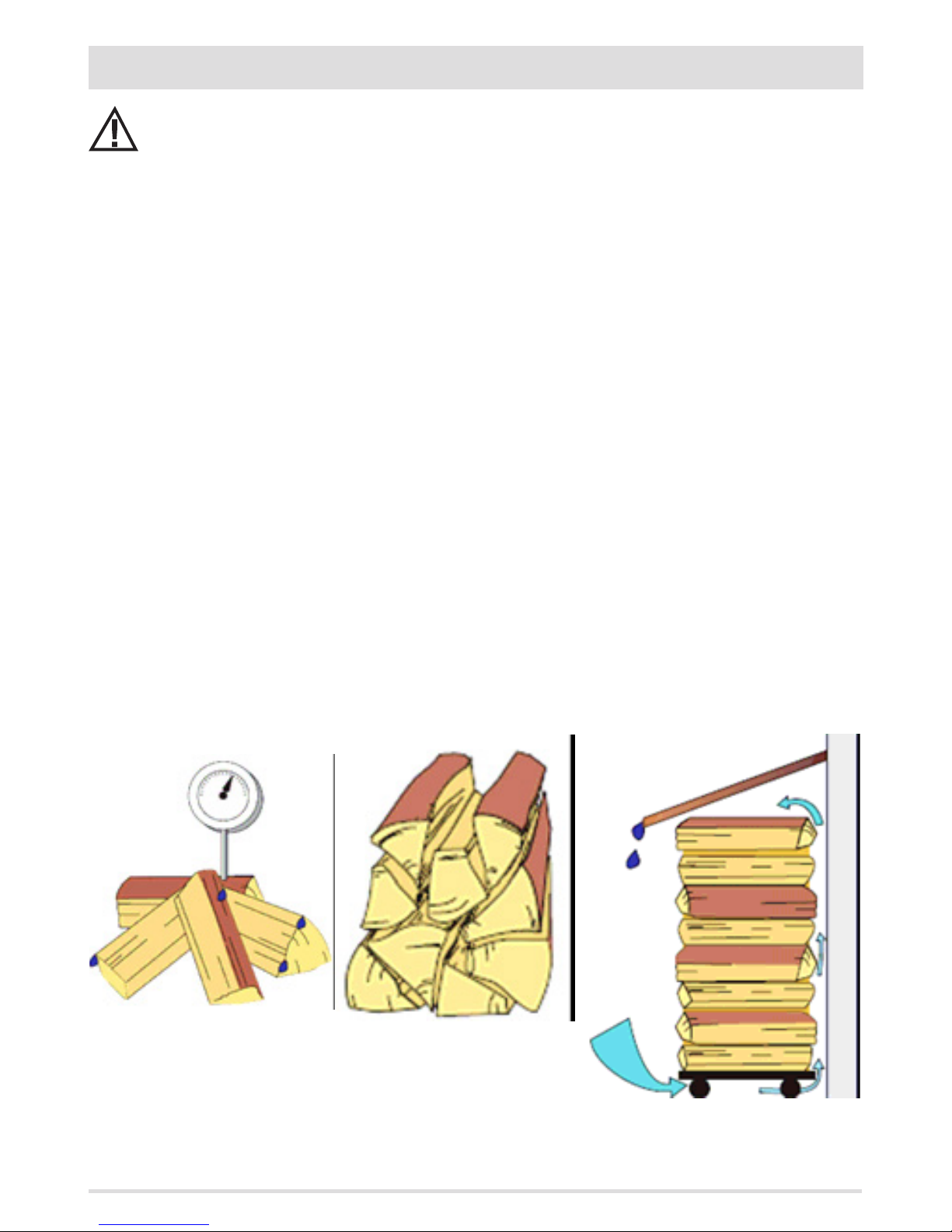
• Only burn natural, untreated wood with maximum humidity of 20%, which corresponds to cut wood with 2 years of correct drying
(FIG.A).
• All types of wood are suitable, both hard and soft: beech, maple, oak, birch, acacia, r, pine, larch, etc.
• Always use wood that is of the right size and not intact, because a whole log impedes the supply of air inside.
• Always burn the wood horizontally and not standing up
• For each load, always use the amount of wood indicated by the manufacturer and do not load one piece after another, because the
ame would never reach a sucient temperature for proper combustion.
• Do not insert an amount above that indicated to prevent excessive ames with excessively high smoke and wall temperatures.
• The thickness and length of the wood must always comply with the manufacturer's indications: the size must be about 7-10 cm and
the length (25 or 30cm) depends on the size of the hearth in the combustion chamber. (FIG.B)
Below are some useful indications for the correct storage of the wood:
• stored wood must already be sized for use.
• optimal drying requires a minimum of 2 years (longer times would not lead to a increased drying).
Storage must be:
• well ventilated and aired (FIG.C)
• covered to protect from rain and protected from sunlight, because the wood would lose quality
• not resting directly on the oor but at a distance of about 20-30 cm to prevent rotting.
• At a distance of about 5-10 cm from walls.
• Possibly outside, otherwise in rooms or cellars that are well ventilated, preventing the formation of mould (always leave the window
open!).
• Wood must always be stored at a sucient safe distance from the combustion unit - always comply with the re and safety
regulations.
FIG.A - MAX HUMIDITY 20% FIG.B - MAX SIZE 7-10 CM
FIG.C - WOOD STORAGE
Page 11
9
2-INSTALLATION INSTRUCTIONS
WOOD
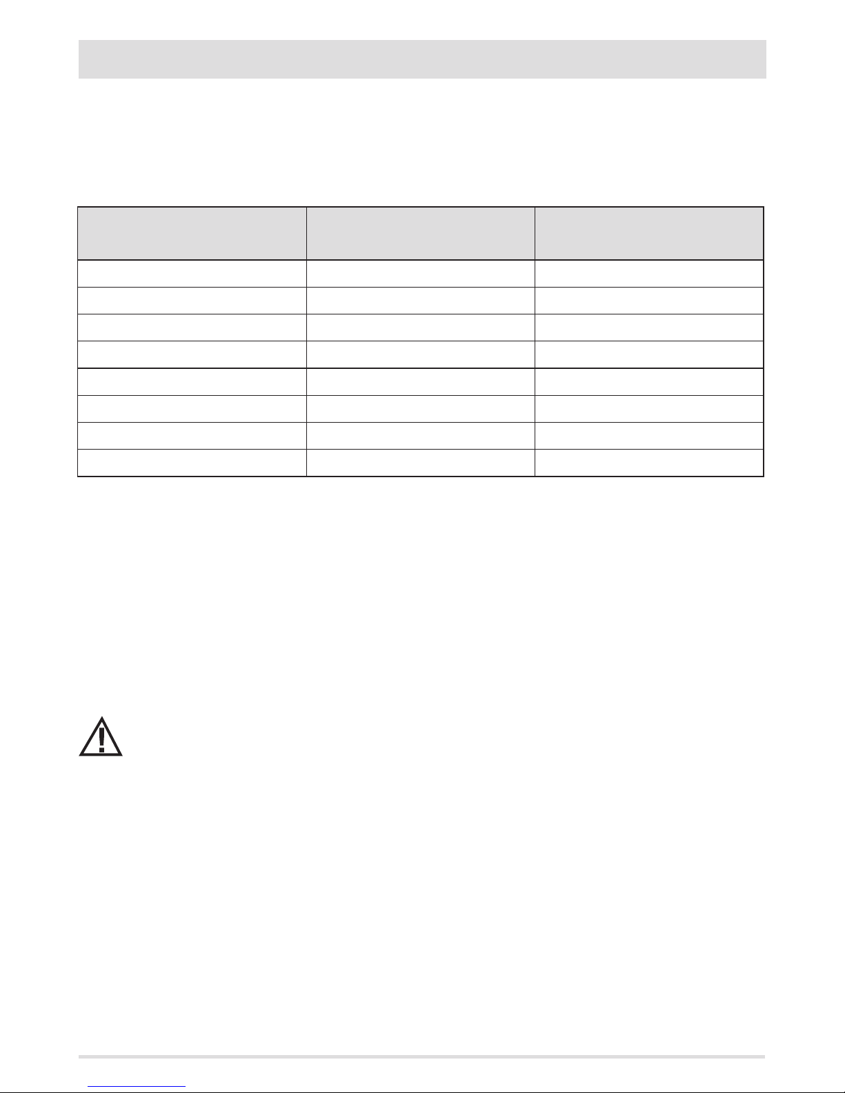
In order to achieve maximum eciency from your product, it is of utmost importance to use wood with suitable characteristics.
Heating wood can be used, such as oak-beech-ash-robinia-common oak or non-resinous pressed wood logs. The latter has a high
caloric value and must be used with caution to avoid harmful overheating of the product. Fuels such as poplar-pine-lime
tree-chestnut have a low caloric value as they are soft wood, i.e. tender. The humidity content is fundamental for all types of wood listed.
Wood drying time
(e.g. beech)
Moisture
%
Caloric value
Kcal/kg
Freshly cut 50 /
3 Months 40 2410
6 Months 35 2700
9 Months 30 2900
12 Months 25 3150
15 Months 20 3400
18 Months 15 3710
21 Months 10 3980
A high percentage of moisture causes condensation in the smoke duct, causing an alteration to the draught and generating smoke and
considerable soot deposits in the rebox, on the glass of the door and on the chimney, with the subsequent risk of this catching re. It also
leads to a much lower overall eciency.
The use of moist or treated wood releases a greater amount of smoke, which could soil the glass more quickly. Poor chimney performance
can also compromise the cleanliness of the glass, as the smoke remains in the combustion chamber longer than usual.
Do not use treated fuels (painted or lacquered wood) or non-compliant fuels (plastic or derivatives), which could
release toxic or polluting substances.
Do not burn waste.
The gasses produced by combustion of unsuitable fuel could damage the product and the chimney, pollute and
compromise your health.
Page 12

10
2-INSTALLATION INSTRUCTIONS
FOREWORD
The installation position must be chosen according to the room, to the smoke extraction system, to the chimney ue. Check with local
authorities whether there are any restrictive regulations in force regarding the combustion air inlet, the smoke outlet system, the ue or
the chimney cap. The manufacturer declines all responsibility in the event of installations that do not comply with the laws in force, incorrect room air exchange, electrical connection non-compliant with the standards and inappropriate use of the appliance. The installation
must be carried out by a qualied technician, who must issue a declaration of conformity of the system to the purchaser and will assume
full responsibility for nal installation and consequent good operation of the product.
In particular one must ensure that:
• there is a suitable combustion air inlet and smoke outlet in compliance with the type of product installed
• other installed appliances or devices do not cause a depression in the room where the product is installed
• when the product is switched on there is no reux of smoke in the room
• fumes extraction takes place in total safety (sizing, smoke seal, distances from ammable materials..).
We especially recommend to check the data tags of the ue for the safety distances that must be observed in presence of
combustible materials and the type of insulating material to be used. These indications must be followed strictly to prevent serious harm to people and the integrity of the home. The installation of the appliance must ensure easy access to clean the
appliance itself, the smoke outlet pipes and the ue. It is forbidden to install the product in rooms with a re hazard. Installation
in studio ats, bedrooms and bathrooms is only allowed with sealed or closed appliances equipped with suitable combustion air ducting directly outside. Always maintain adequate distance and protection in order to prevent the product from
coming into contact with water.
In the event there are several appliances installed, the external air inlet must be sized accordingly.
MINIMUM DISTANCES
It is recommended to install the stove detached from any walls and/or furniture, with a minimum clearance to allow eective aeration
of the appliance and a good distribution of heat in the room. Observe the distances from ammable or heat-sensitive objects (sofas,
furniture, wood panelling, etc.) as specied in the technical data table. The frontal distance from ammable materials must be at least
as specied in the product's technical data table.
If particularly delicate objects are present, such as furniture, curtains or sofas, increase the stove clearance accordingly.
If the oor is made of wood, it is recommended to t a oor protection sheet in compliance with the Standards in
force in the country of installation.
If the oor is made of combustible material, it is recommended to use protection made of non-combustible material (steel, glass...) that
also protects the front from falling combusted material during cleaning operations.
The appliance must be installed on a oor with adequate load capacity.
If the existing construction does not meet this requirement, one must take appropriate measures (for example a load distribution plate).
Page 13
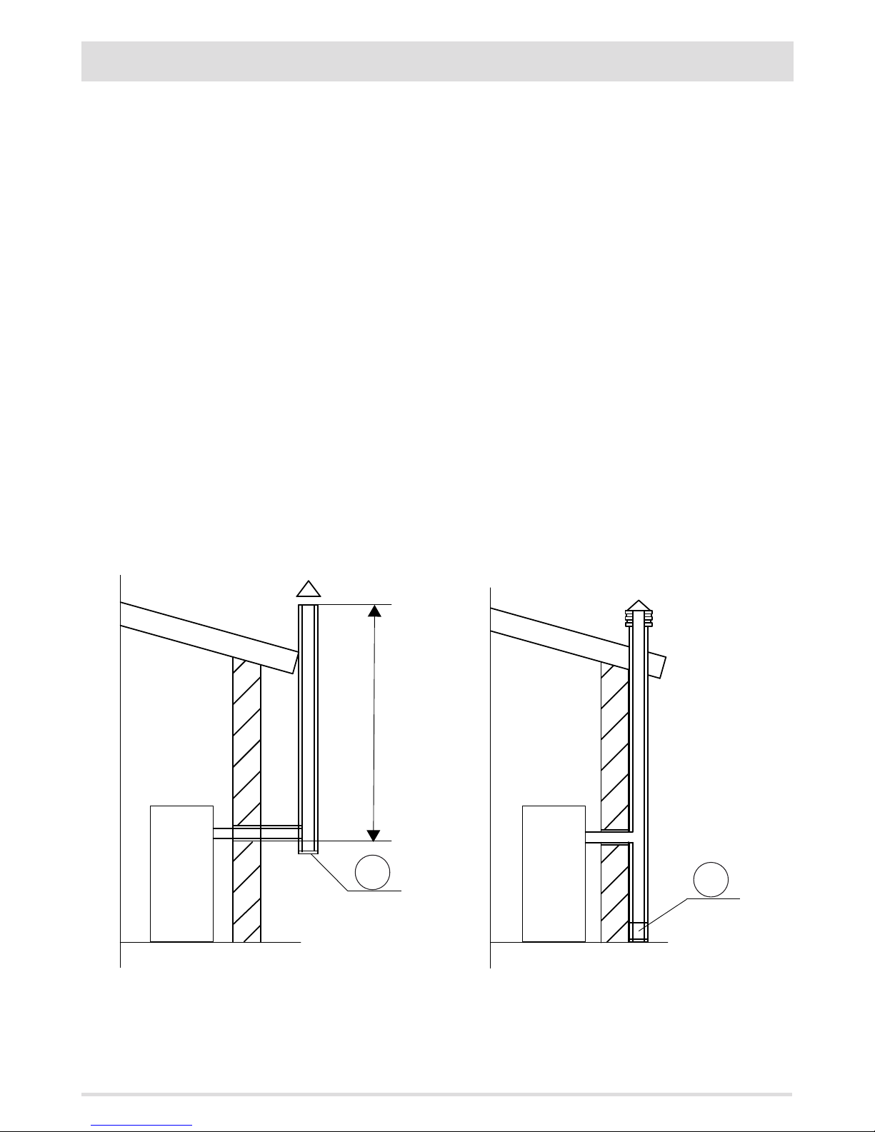
min.3,5 metri
AT
(A)
AP
(B)
11
2-INSTALLATION INSTRUCTIONS
FIGURE 1 - SMOKE FLUE
FOREWORD
This Flue chapter has been drawn up with reference to the provisions of European Standards (EN13384 - EN1443 - EN1856 - EN1457).
The chapter provides indications for installing an ecient and correct smoke ue but is under no circumstances to substitute the regulations in force, which the qualied technician must be in possession of. Check with local authorities whether there are any restrictive
regulations in force regarding the intake of air for combustion, the smoke extraction system, the ue or the chimney.
The company declines all liability relating to the poor functioning of the oven if this is due to the use of an insuciently sized ue in
violation of the Standards in force.
SMOKE FLUE
The ue or chimney is of great importance for the proper operation of a solid fuel-burning heating appliance with natural draught, as
modern heating appliances have high eciency with cooler ue gas and consequently less draught, it is therefore essential that the ue is
built to a high standard and always kept in perfect working order. A ue that serves a wood-burning appliance must be at least category
T400 (or greater if the appliance requires so) and resistant to soot res. Smoke must be extracted through a single ue made of insulated
steel (A) or an existing ue that complies with the intended use (B).
A simple air shaft in cement must be suitably lined. In both solutions there must be an inspection cap (AT) and/or inspection hatch (AP)
- FIG.1.
It is prohibited to connect more than one wood/pellet or any other type of appliance (vent cowling...) to the same ue.
Page 14
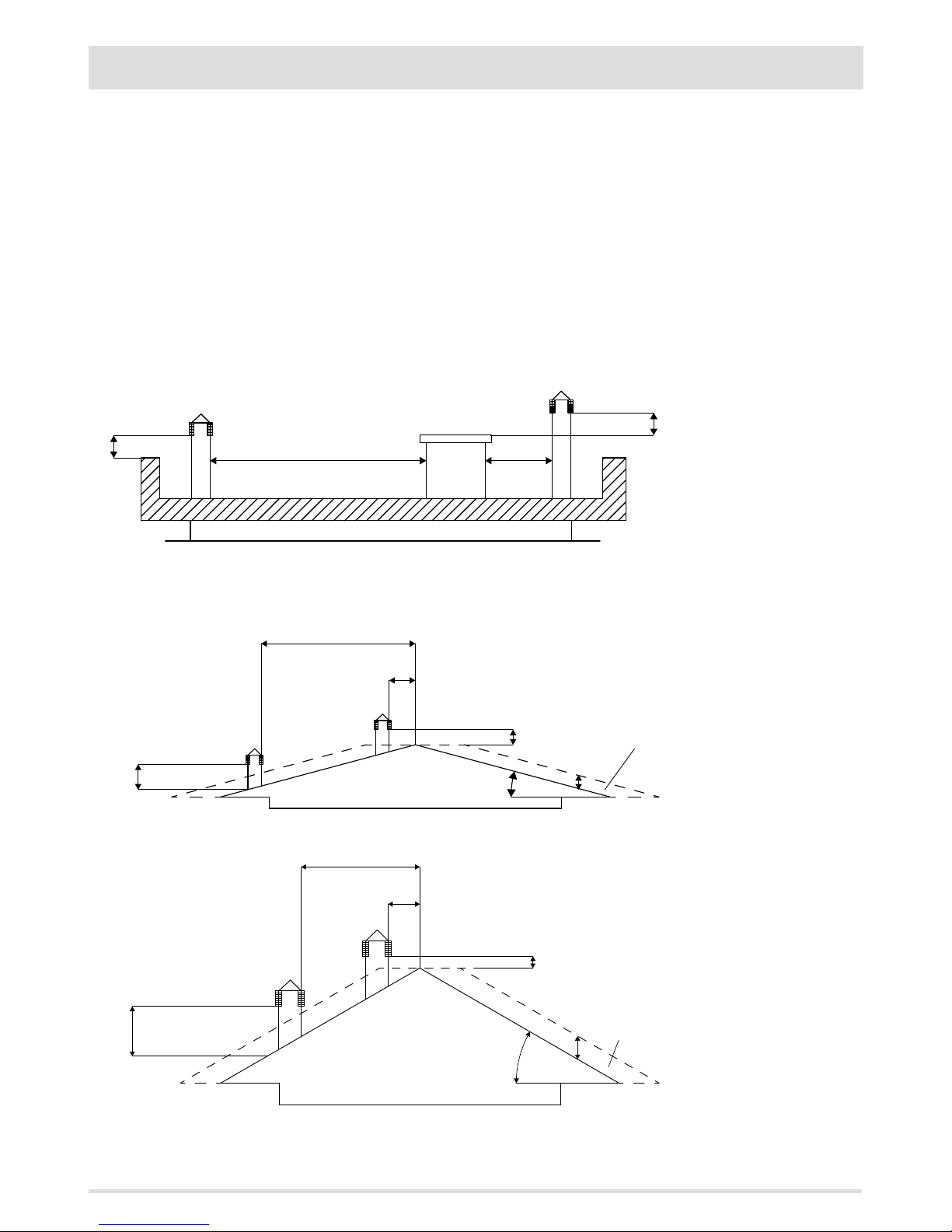
A
B
C
D
E
A
B
C
D
15°
E
F
A
B
C
D
E
30°
F
12
2-INSTALLATION INSTRUCTIONS
A = 0.50 metres
B = DISTANCE > 2 metres
C = DISTANCE < 2 metres
D = O.50 metres
E = TECHNICAL VOLUME
A = MIN. 1.00 metres
B = DISTANCE > 1.85 metres
C = DISTANCE < 1.85 metres
D = 0.50 metres above highest point
E = 0.50 metres
F = REFLUX ZONE
A = MIN. 1.30 metres
B = DISTANCE > 1.50 metres
C = DISTANCE < 1.50 metres
D = 0.50 metres ABOVE HIGHEST POINT
E = 0.80 metres
F = REFLUX ZONE
FIGURE 2
FIGURE 3
FIGURE 4
TECHNICAL CHARACTERISTICS
Have the eciency of the ue checked by an authorised technician.
The ue must be sealed against ue gasses, in a vertical direction without narrowing, be made with materials impermeable to smoke,
condensation, thermally insulated and suitable to resist normal mechanical stress over time (we recommend replaces made of A/316
or refractory material with insulated round section double chamber). Be suitably insulated externally to avoid condensation and reduce
smoke cooling. It should be separated from combustible or ammable materials with an air gap or insulating materials: check the distance
specied by the manufacturer of the replace according to EN1443. The chimney opening must be in the same room as the appliance, or
at most in the adjoining room, and have a soot and condensation collection chamber beneath the opening, and be accessible via a sealed
metal hatch.
FLAT ROOF
ROOF AT 15°
ROOF AT 30°
Page 15
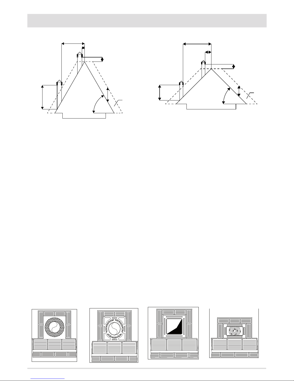
A
B
D
60°
E
C
F
A
B
C
D
E
45°
F
13
2-INSTALLATION INSTRUCTIONS
A = MIN. 2.60 metres
B = DISTANCE > 1.20 metres
C = DISTANCE < 1.20 metres
D = 0.50 metres ABOVE HIGHEST POINT
E = 2.10 metres
F = REFLUX ZONE
A = MIN. 2.00 metres
B = DISTANCE > 1.30 metres
C = DISTANCE < 1.30 metres
D = 0.50 metres ABOVE HIGHEST POINT
E = 1.50 metres
F = REFLUX ZONE
FIGURE 5 FIGURE 6
ROOF AT 60° ROOF AT 45°
DIMENSIONING
The drop in pressure (draft) of a ue depends on its height. Check the drop in pressure with the values indicated in the technical characteristics. The minimum height of the chimney is 3.5 meters.
The interior cross-section of the ue can be circular (best variation), square or rectangular (the ratio between the interior sides must be
≤1.5) with the sides joined with a minimum radius of 20 mm. The size of the section must be at least equal to that of the appliance outlet
(smaller diameters must be conrmed by an adequate system sizing calculation).
The cross-sections/lengths of the chimneys shown in the technical data tables are indications for correct installation. Any alternative
congurations must be correctly dimensioned in accordance with the general method of calculation of UNI EN13384-1 or other proven
eciency methods.
Below is a list of some ues available on the market:
Steel chimney AISI 316 with
double chamber insulated with
ceramic bre or equivalent
resistant up to 400°C.
Refractory chimney with
double insulated chamber and
external lightweight concrete
cladding with cellular material
such as clay.
Traditional square-section clay
chimney with insulating empty
inserts.
Avoid products with an internal
rectangular section where the
larger side is 1.5 times the
smaller side (e.g. 20x40 or
15x30).
EXCELLENT GOOD POOR VERY POOR
Page 16
1
9
9
2
3
4
5
6
7
8
14
2-INSTALLATION INSTRUCTIONS
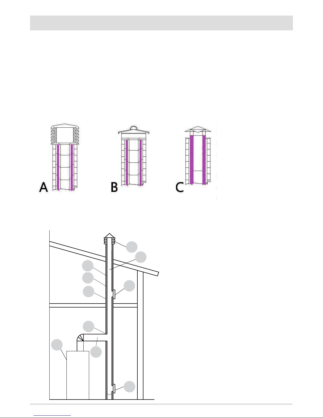
KE Y:
(1) CHIMNEY
(2) REFLUX CHANNEL
(3) SMOKE DUCT
(4) THERMAL INSULATION
(5) OUTSIDE WALL
(6) CHIMNEY CONNECTION
(7) SMOKE CHANNEL
(8) HEAT GENERATOR
(9) INSPECTION ACCESS PANEL
FIGURE 7
FIGURE 8
MAINTENANCE
The ue must be kept clean, since the deposit of soot or unburned oils reduces the cross-section reducing the draught, thus compromising
the ecient operation of the product and, if large build-ups accumulate, they can catch re. The ue and chimneypot must be cleaned
and checked by a qualied chimney sweep at least once a year. Once the inspection/maintenance has been performed, request a written
report that the system is safe.
Failure to perform cleaning jeopardises the system's safety.
CHIMNEY
The chimney is a crucial element for the heating appliance to work properly: we recommend a wind proof chimney (A), see Figure 7.
The area of the opening for smoke extraction must be at least double the cross-section of the smoke duct/ue system, and arranged so
that smoke extraction is ensured even
in strong wind. The chimney must prevent rain, snow or animals from entering the chimney. The height of outow
into the atmosphere must be beyond
the reux zone created by the shape
of the roof or any obstacles near the
outlet (see Figures 2-3-4-5-6).
CHIMNEY COMPONENTS
Page 17
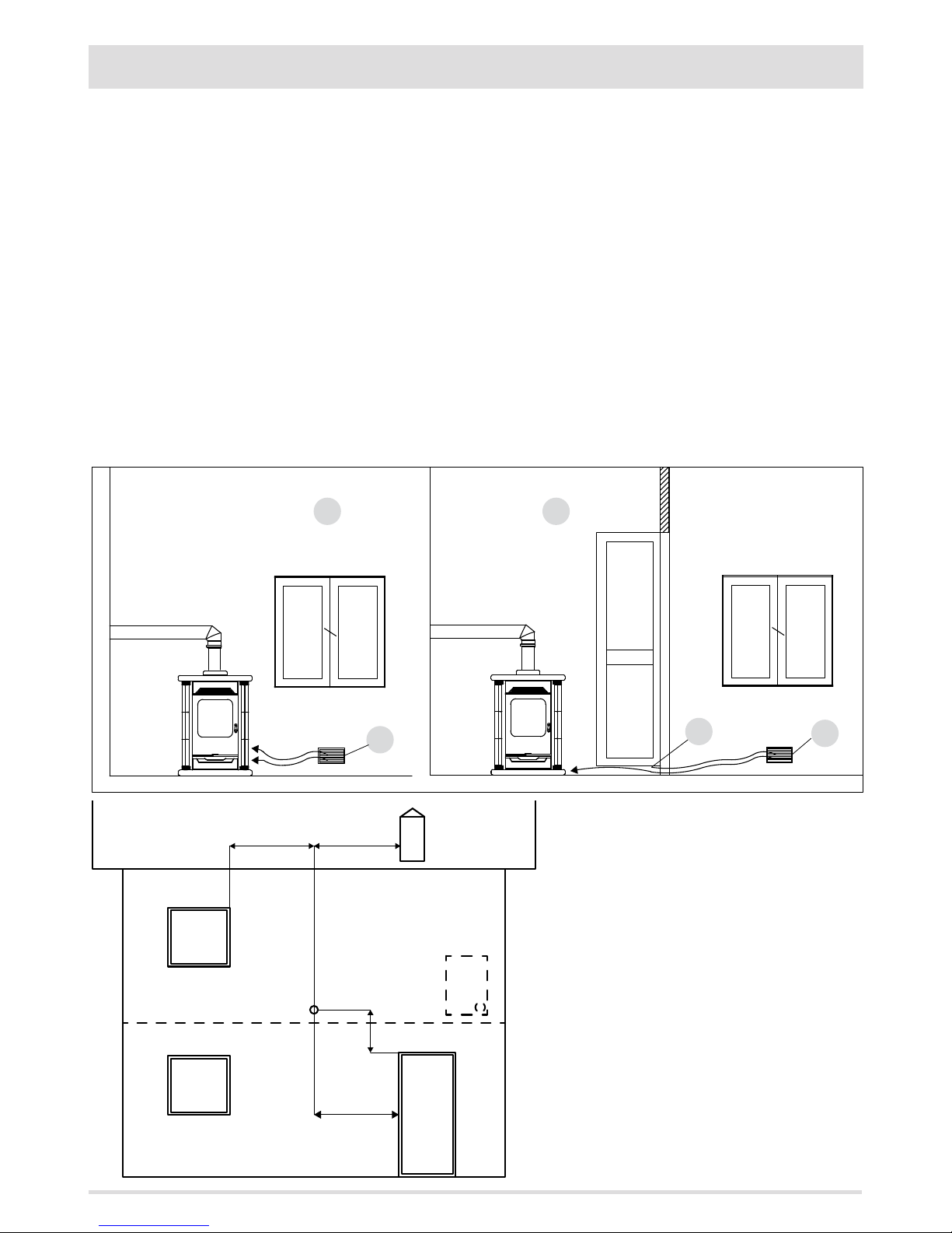
A
A B
A
C
MIN.1,5 m MIN.1,5 m
MIN.1,5 m
MIN.0,3 m
15
2-INSTALLATION INSTRUCTIONS
FIGURE 9 A - DIRECTLY FROM OUTSIDE
FIGURE 10
FIGURE 9 B - INDIRECTLY FROM THE ADJACENT ROOM
A=AIR INLET
B=ROOM TO BE VENTILATED
C=INCREASE OF THE GAP UNDER THE DOOR
EXTERNAL AIR INLET
It is mandatory to provide an adequate external air intake that supplies the combustion air required for the product to work properly. The
ow of air between the outside and the installation room may be direct, through an inlet in an external wall of the room; or indirect, via
air intake from adjoining rooms and connecting permanently with the installation room (see Figure 9 b). Adjoining areas may not include
sleeping areas, garages or general areas with a re hazard. During installation one must check the minimum clearances required for air
intake from outside. Take into account the presence of doors and windows that could interfere with the proper ow of air to the product
(see diagram below).
The air inlet must have a minimum total net area of 100 cm2 (for stoves - 150 cm2 for replaces/inserts): the surface must be increased
accordingly if within the room there are other active generators (for example: electric fan for stale air extraction, kitchen hood, other
stoves, etc...), which could cause a depression in the room. It is required to check that, with all appliances on, the pressure drop between
the room and the outside does not exceed the value of 4 Pa (also for Oyster appliances if the combustion air has not been suitably ducted
outside. If necessary increase the intake section of the air inlet, which must be made at oor level and always protected with a bird-proof
outer protection grid and in such a way that it cannot be obstructed by any object.
You can connect the air required for combustion directly to the external air inlet, with a non-compressible pipe (e.g. spiral). For air ducts
up to 3 m, increase the cross-section by approximately 5%, longer ducts increase it by 15%.
Page 18
16
2-INSTALLATION INSTRUCTIONS
For appliances installed in studio ats, bedrooms and bathrooms (where allowed), it is mandatory to connect the combustion air to the
outside. In particular for sealed products the connection must be sealed in order not to compromise the overall sealed characteristic of
the system.
DISTANCE (metres) The air inlet must be at a distance of:
1.5 m UNDER Windows, doors, smoke outlets, cavities, ....
1.5 m HORIZONTALLY Windows, doors, smoke outlets, cavities, ....
0.3 m ABOVE Windows, doors, smoke outlets, cavities, ....
1.5 m AWAY from smoke outlet
CONNECTION TO FLUE
The connection between the ue and the appliance must be via a smoke duct that conforms with EN 1856-2. To connect the replace to
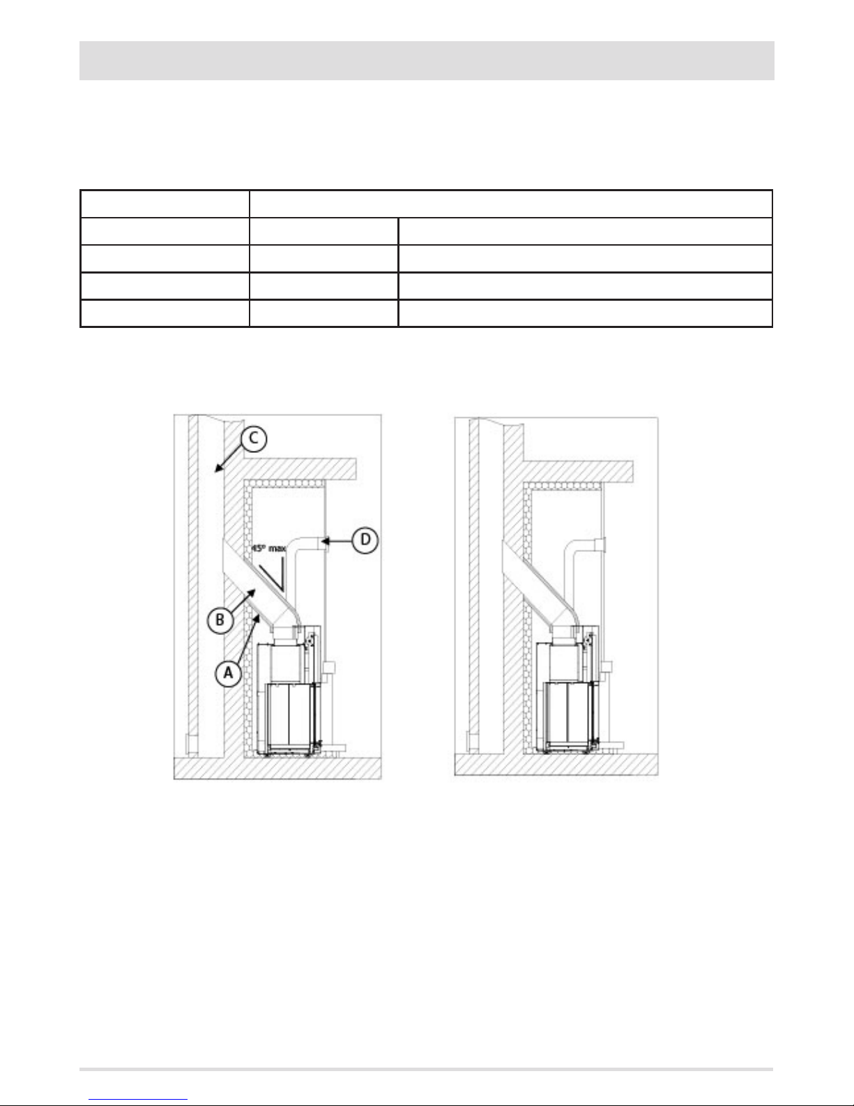
the chimney ue or to a ceiling connection that is not coaxial to the unit's smoke outlet, changes of direction must be made using open
bends no greater than 45° with respect to the vertical.
For stoves the connecting section to the ue must extend no more than 2 m horizontally, with a minimum slope of 3% and with a maximum of 3 90° bends (accessible for inspection - do not count the T tting at the unit outlet).
The diameter of the smoke duct must be equal to or greater than that of the appliance outlet. A possible increase/reduction of the crosssection is only allowed when the ue is connected (in particular the reduction must be conrmed by an adequate system sizing calculation).
EXAMPLE OF HYDRO FIREPLACE FITTING
A. CERAMIC FIBRE INSULATION
B. SMOKE FITTING
C. CHIMNEY FLUE
D. HOOD GRID
TYPICAL DIAGRAM OF A CORRECTLY LAID CHIMNEY FLUE
WITH, AT THE FOOT OF THE EXTERNAL UPDRAFT SECTION,
THE POSITIONING OF A CHAMBER WITH A SEALED
HATCH TO COLLECT AND REMOVE THE SOLID MATERIALS
PRODUCED DURING COMBUSTION.
Page 19
17
2-INSTALLATION INSTRUCTIONS
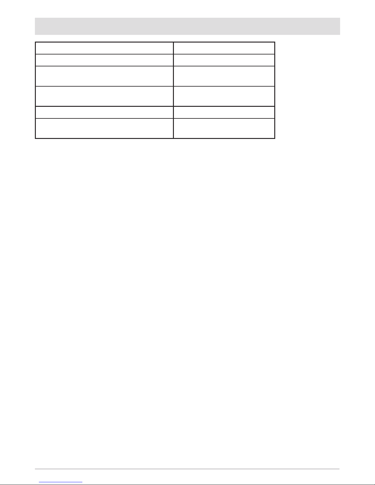
TYPE OF DEVICE SMOKE DUCT
Minimum vertical length 1.5 metres
Maximum length
(with 1 accessible 90° bend)
4.5 metres
Maximum length
(with 3 accessible 90° bends)
2.5 metres
Maximum number of accessible 90° bends 3
Horizontal sections
(minimum incline 3%)
2 metres
Use smoke ducts that are able to withstand the unit operating temperatures (min. T400). The use of exible metal tubes in bre
cement or aluminium is prohibited. For direction changes, we always recommend the use of a T joint with an inspection cap
allowing easy access for cleaning the tubes. Always ensure that the inspection cap is replaced and hermetically sealed with the seal in
tact after cleaning.
It is prohibited to connect more than one appliance to the same smoke duct, or the discharge from overhead cowling. It is prohibited to
extract the products of combustion directly through the wall, whether into indoor spaces or outdoors.
The smoke duct must be installed observing the safety distances from ammable materials as specied on its rating plate (e.g. G400=
400 mm).
Page 20
S
I
U
B
A
P
U
I
I
C
4
3
D
2
E
U
1
F
18
2-INSTALLATION INSTRUCTIONS
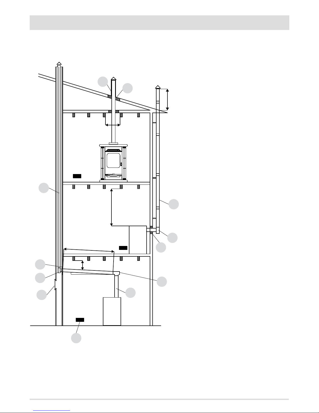
FIGURE 11
U = INSULATING
I = INSPECTION CAP
S = INSPECTION ACCESS PANEL
P = AIR INLET
A = MINIMUM 40 MM
B = MAXIMUM 2 M
C = MINIMUM 3°
D = MINIMUM 400 MM
E = HOLE DIAMETER
F = SEE FIG.2-3-4-5-6
EXAMPLES OF CORRECT INSTALLATION
1. Installation of Ø200mm ue with hole for the passage
of the pipe increased by:
minimum 100 mm around the tube if next to non ammable parts such as cement, brick, etc.; or
minimum 400mm around the pipe (or as required by
data tags) if next to ammable parts such as wood etc.
In both cases, install suitable insulation between the ue
and the ceiling.
Always check and respect the data tags on the ue, in
particular the minimum safety distances from combustible materials.
The previous rules also apply for holes made in walls.
2. Old ue, minimum tube Ø150mm with the inclusion of
an external access door for chimney cleaning.
3. External ue made of insulated stainless steel tubes,
i.e. with double walls minimum Ø150mm: all securely
mounted to the wall. With wind-proof chimney. See g.
7 type A.
4. Ducting system using T ttings that allow easy access
for cleaning without having to remove the pipes.
NOTE: in the event of hydro replaces maintain the safety
distance indications with the included insulation indications.
Page 21
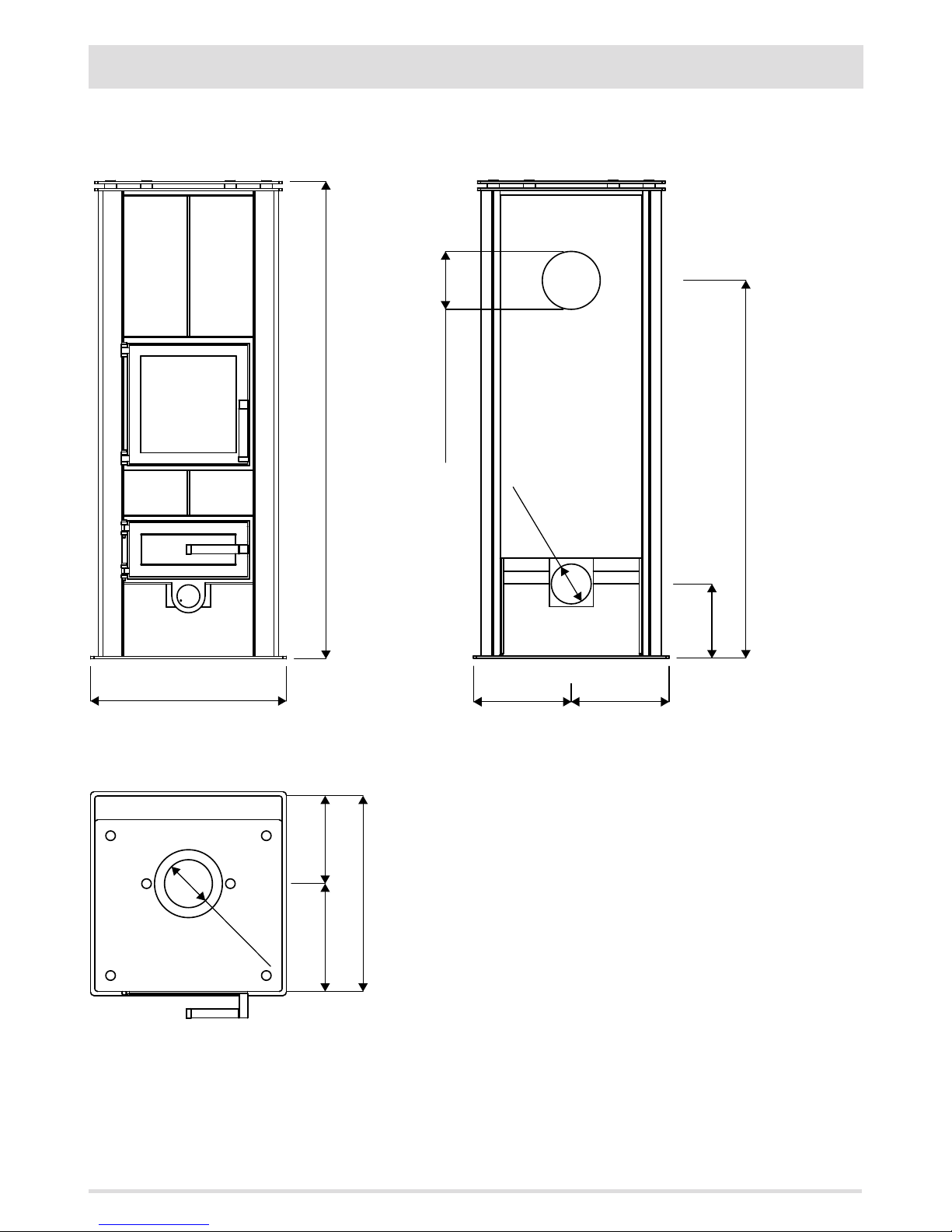
490 - L
1200 - H
Ø120
270
220
220
490 - B
Ø120 OPTIONAL
Ø100
245
950
245
190
19
3-DIMENSIONS AND TECHNICAL FEATURES
ASKO LINE
ASKO Le06
3DIMENSIONS AND TECHNICAL FEATURES
Page 22
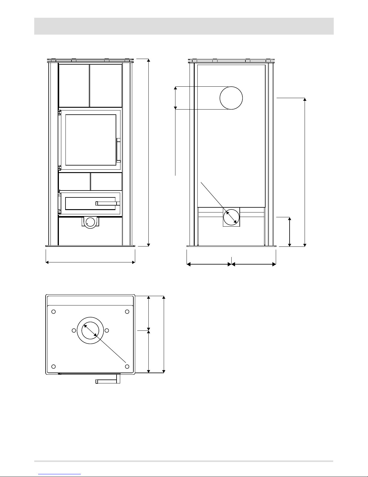
270 220
490 - B
Ø120
570 - L
1200 - H
Ø100
285
950
285
190
Ø120 OPTIONAL
20
3-DIMENSIONS AND TECHNICAL FEATURES
ASKO Le08
Page 23
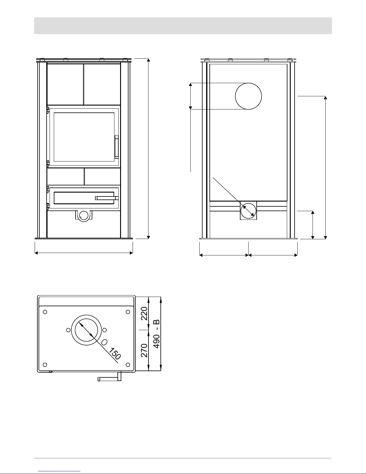
325 325
190
950
Ø100
Ø120 OPTIONAL
650 L
1200 - H
21
3-DIMENSIONS AND TECHNICAL FEATURES
ASKO Le10
Page 24
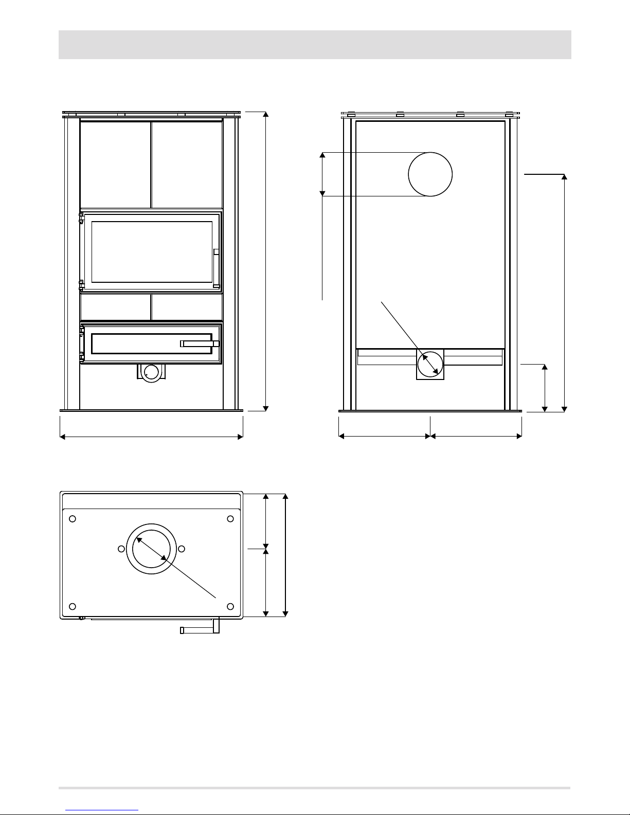
Ø150 OPTIONAL
Ø100
730 - L
1200 - H
490 - B
220
270
190
950
365 365
Ø150
22
3-DIMENSIONS AND TECHNICAL FEATURES
ASKO Le12
Page 25
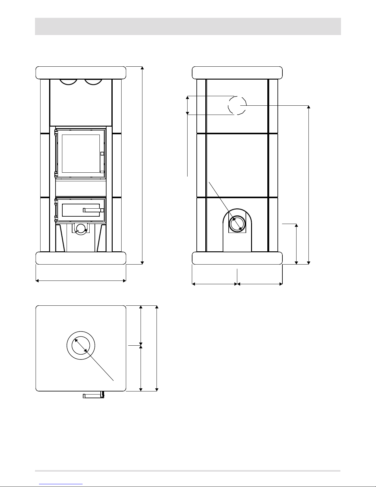
Ø120
290 290
550 - B
260290
260
1020
580 - L
1270 - H
Ø120 OPTIONAL
Ø100
23
3-DIMENSIONS AND TECHNICAL FEATURES
ST.MORITZ LINE
ST.MORITZ Le06
Page 26
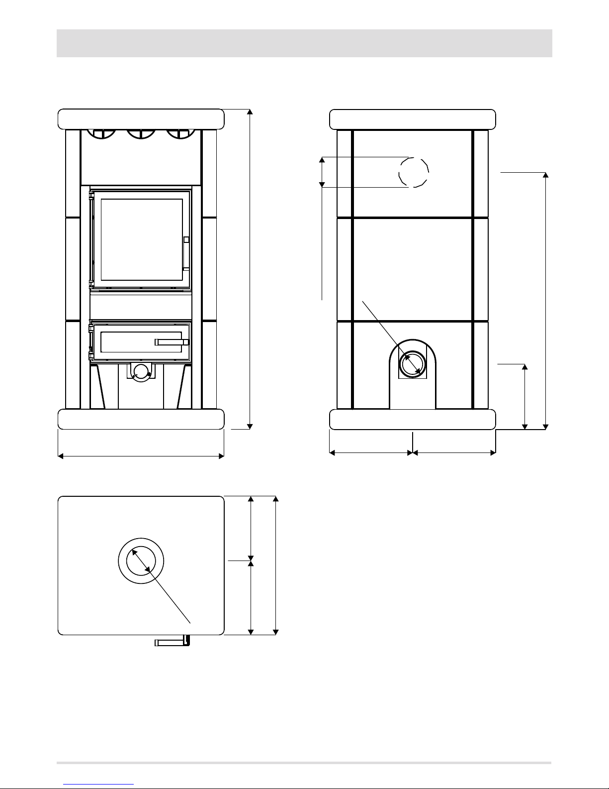
660 - L
550 - B
Ø120
290
260
1270 - H
Ø120 OPTIONAL
Ø100
330 330
1020
260
24
3-DIMENSIONS AND TECHNICAL FEATURES
ST.MORITZ Le08
Page 27
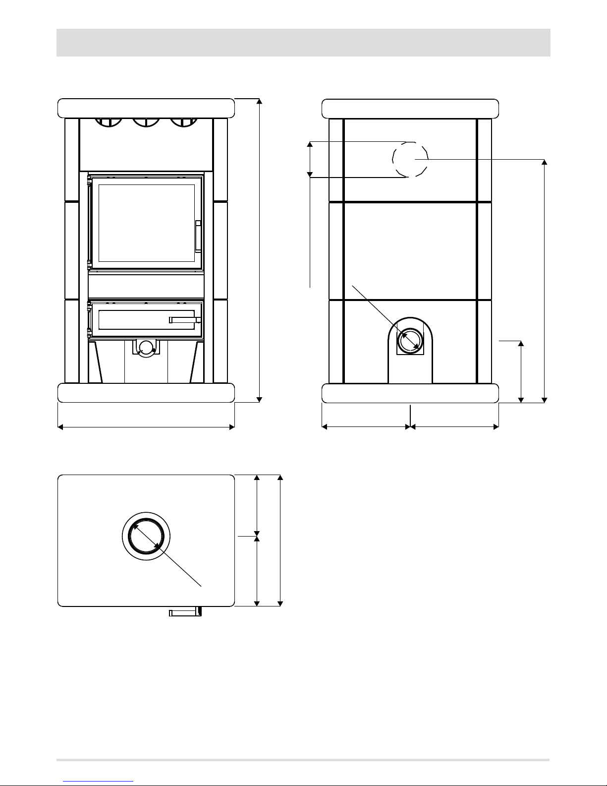
Ø150
550 - B
260290
740 - L
1270 - H
Ø150 OPTIONAL
Ø100
370
370
260
1020
25
3-DIMENSIONS AND TECHNICAL FEATURES
ST.MORITZ Le10
Page 28
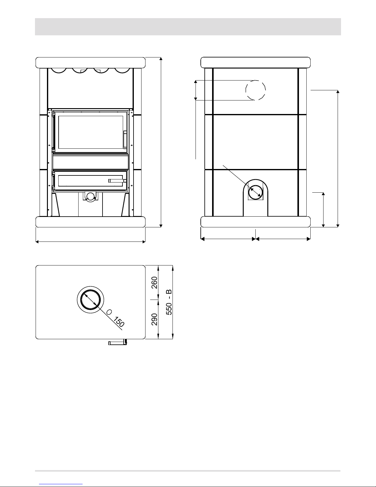
820 - L
1270 - H
Ø150 OPTIONAL
Ø100
410 410
260
1020
26
3-DIMENSIONS AND TECHNICAL FEATURES
ST.MORITZ Le12
Page 29
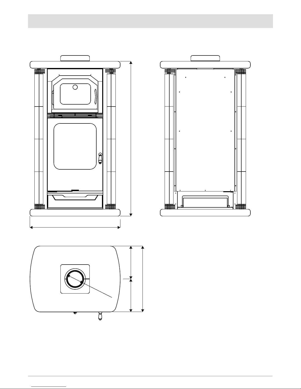
780 - L
1340 - H
Ø150
570 - B
285 285
27
3-DIMENSIONS AND TECHNICAL FEATURES
CHAMONIX LINE
CHAMONIX Lf10
Page 30
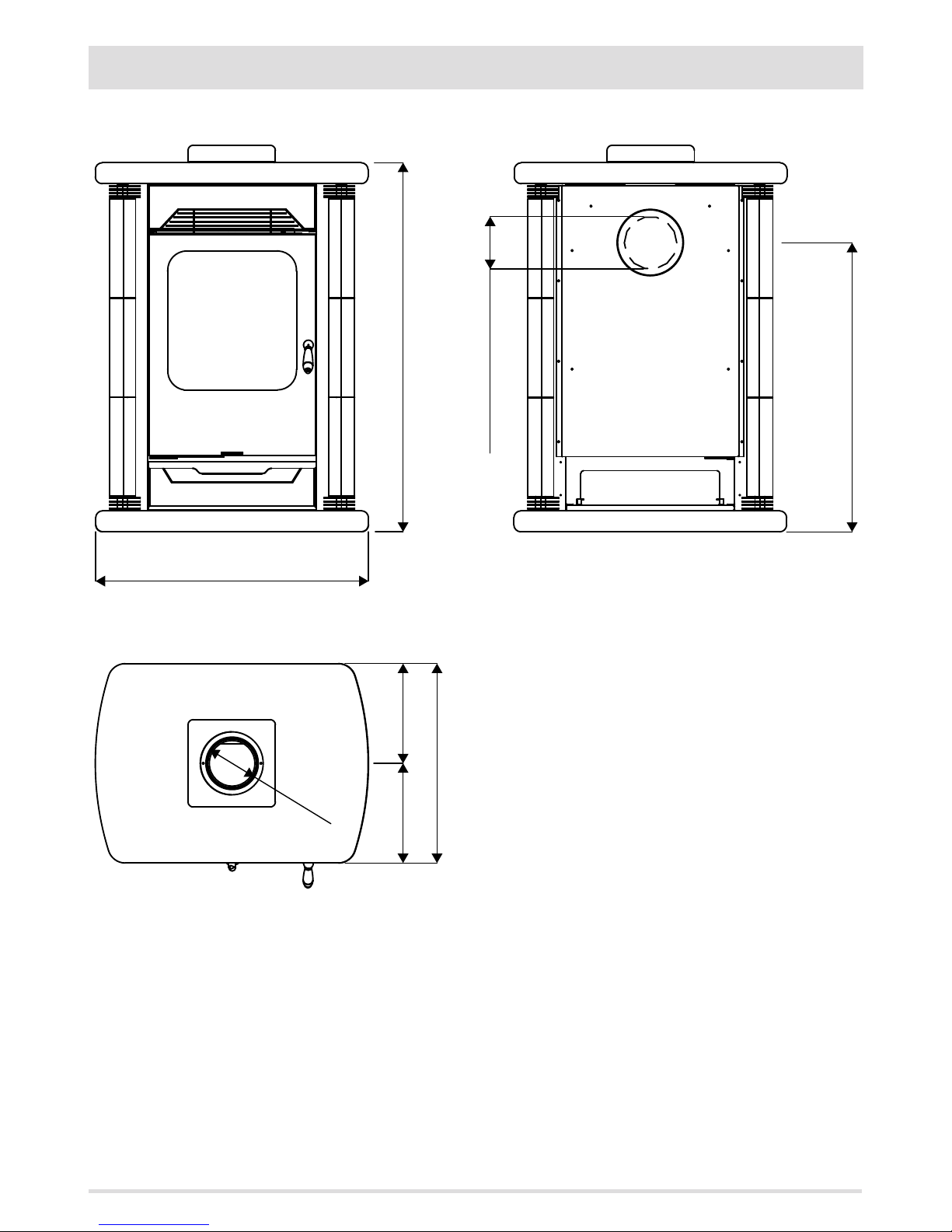
285 285
570 - B
Ø150
780 - L
1060 - H
Ø150 OPTIONAL
830
28
3-DIMENSIONS AND TECHNICAL FEATURES
CHAMONIX Le11
Page 31
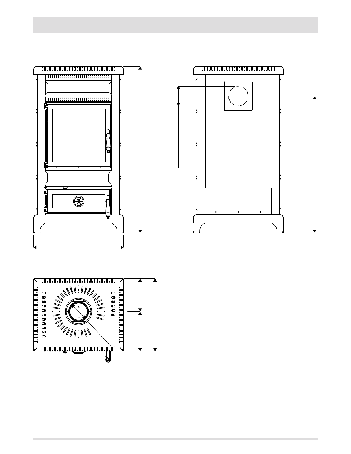
550 - L
1000 - H
Ø120 OPTIONAL
830
440 - B
Ø120
240 200
29
3-DIMENSIONS AND TECHNICAL FEATURES
CORTINA LINE
CORTINA Le09
Page 32
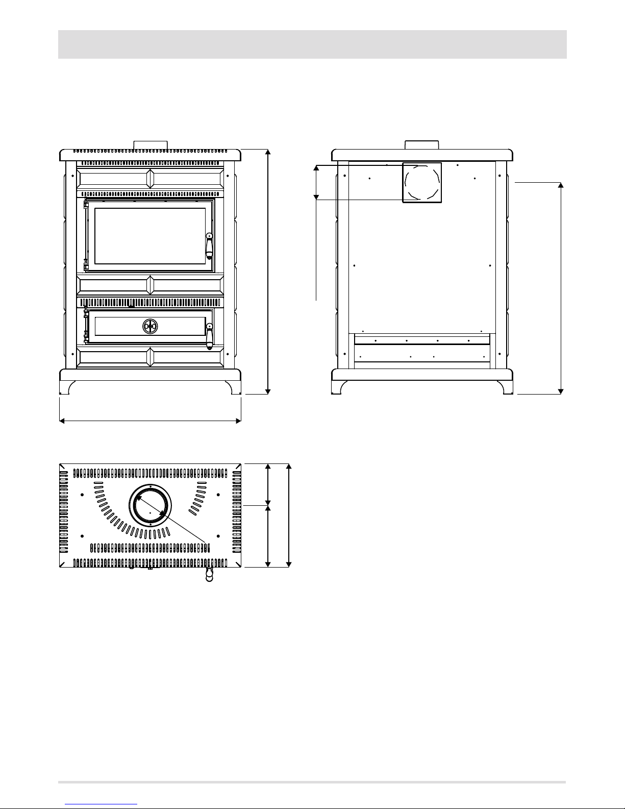
790 - L
1060 - H
Ø150 OPTIONAL
920
450 - B
Ø150
270 180
30
3-DIMENSIONS AND TECHNICAL FEATURES
CORTINA Le10
Page 33
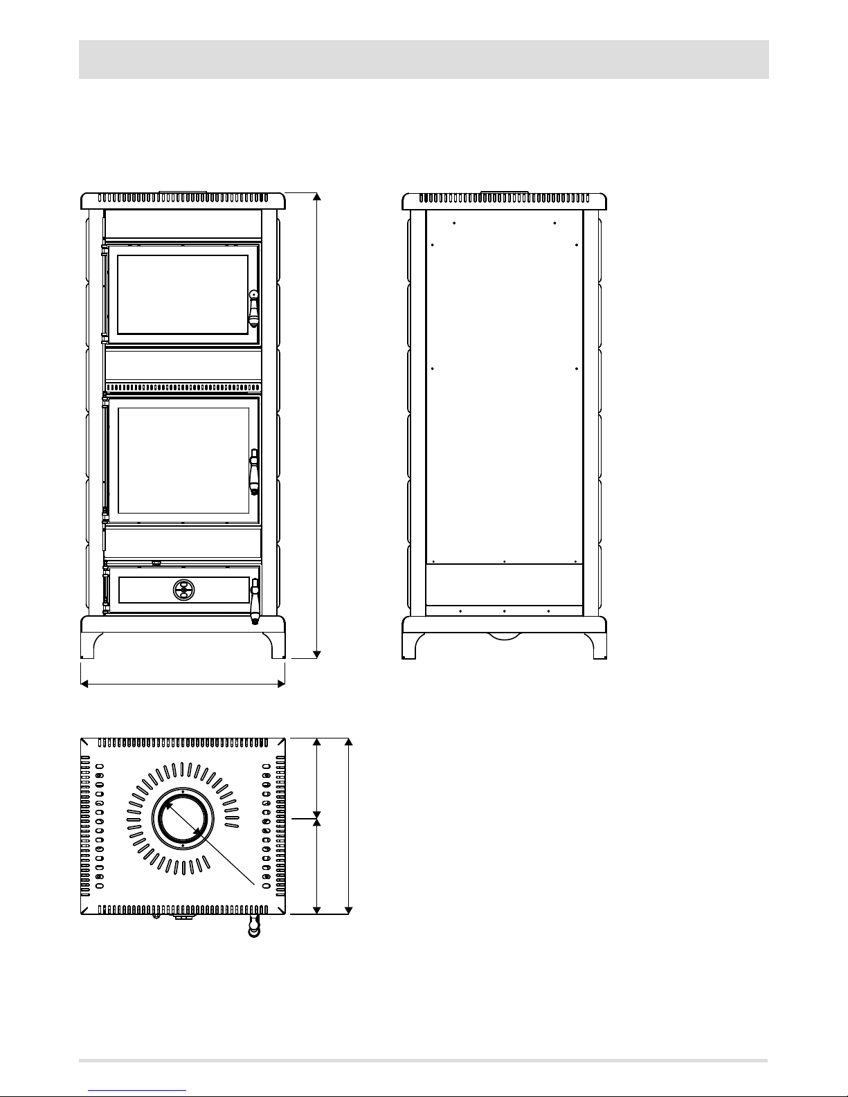
1430 - H
540 - B
250290
Ø150
630 - L
31
3-DIMENSIONS AND TECHNICAL FEATURES
CORTINA Lf11
Page 34
32
3-DIMENSIONS AND TECHNICAL FEATURES
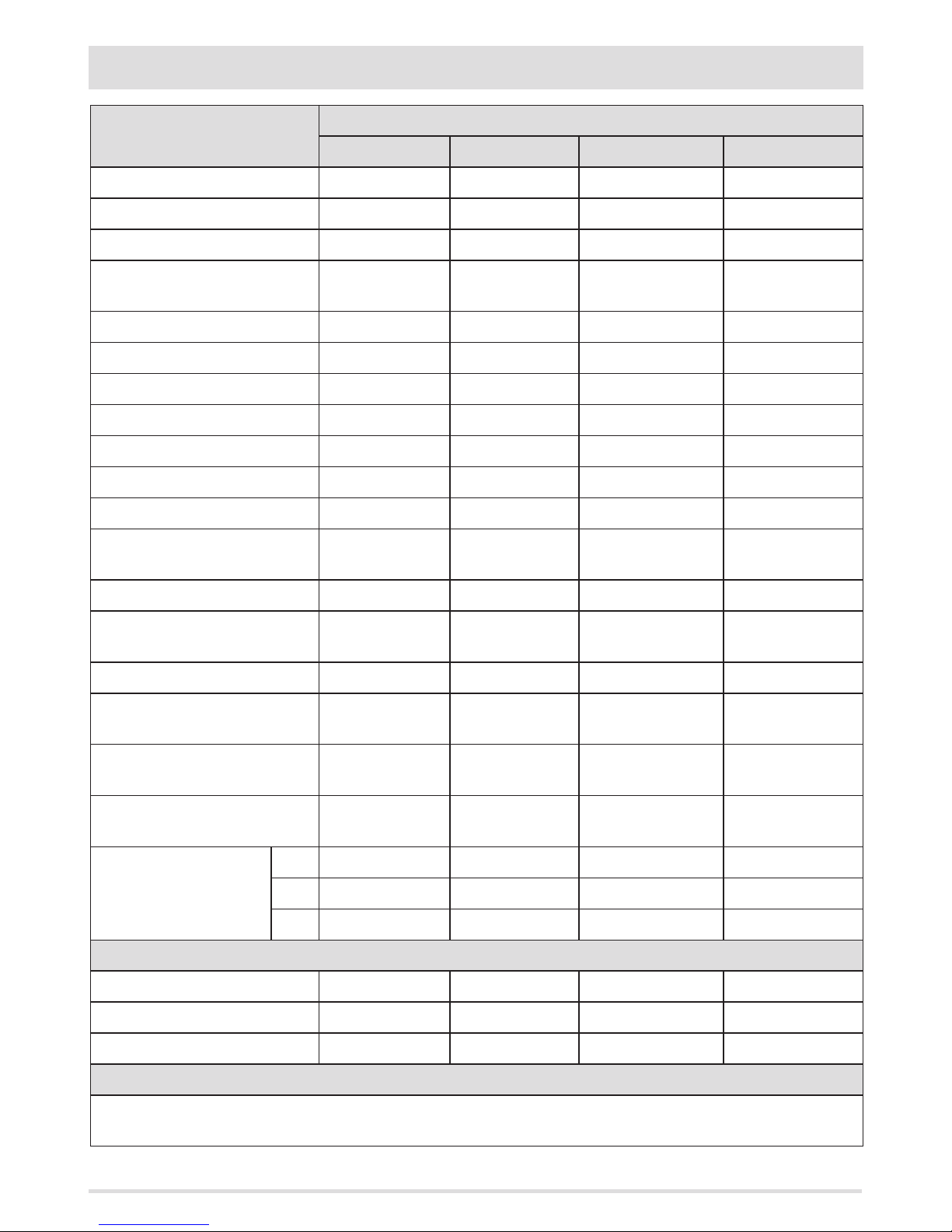
TECHNICAL CHARACTERISTICS
ASKO
Le06 Le08 Le10 Le12
Type of fuel Wood Wood Wood Wood
Hourly consumption 1.9 kg/h 2.2 kg/h 2.7 kg/h 3.4-1.7 kg/h
Reloading/load time 45 min / 1.4 kg 45 min / 1.7 kg 45 min / 2.0 kg 45 min / 2.6 kg
Nominal output power 7.0 kW (6020
kcal/h)
8.0 kW (6880
kcal/h)
9.5 kW (8170 kcal/h) 12.0 kW (10320
kcal/h)
Minimum power output - - - 6,0 kW (5160 kcal/h)
Eciency 87,5% 85,0% 85,0% 84,5%
CO emission in fumes (13% O2) 0.08% 0.06% 0.05% 0.10%
Particulate/OGC/Nox (13%O2) 11-14-53 mg/Nm3 14-12-54 mg/Nm3 14-12-54 mg/Nm3 27-19-84 mg/Nm3
Smoke mass ow rate 4.7 g/s 6.1 g/s 7.4 g/s 8.8 g/s
Smoke temperature 193°C 205°C 217°C 227°C
Recommended draught 0.12 mbar - 12 Pa 0.12 mbar - 12 Pa 0.12 mbar - 12 Pa 0.12 mbar - 12 Pa
Heatable volume m3 151/40 - 172/35 -
201/30*
172/40 - 197/35 229/30*
204/40 - 233/35 272/30*
258/40 - 295/35 344/30*
Smoke outlet Ø12 cm Ø12 cm Ø15 cm Ø15 cm
Net weight 210 kg (48 kg stone) 232 kg (49 kg
stone)
255 kg (50 kg stone) 276 kg (51 kg stone)
External air inlet 100 cm2 100 cm2 100 cm2 100 cm2
Distance from ammable material
(back)
300 mm 300 mm 300 mm 300 mm
Distance from ammable material
(side)
400 mm 400 mm 400 mm 400 mm
Distance from ammable material
(underneath)
0 mm 0 mm 0 mm 0 mm
Dimensions
L 490 mm 570 mm 650 mm 730 mm
B 490 mm 490 mm 490 mm 490 mm
H 1200 mm 1200 mm 1200 1200 mm
Flue
Up to 5 m
20x20 cm Ø20 20x20 cm Ø20 20x30 cm Ø22 20x30 cm Ø22
Between 5 and 7 m
18x18 cm Ø18 18x18 cm Ø18 20x20 cm Ø20 20x20 cm Ø20
Beyond 7 m
15x15 cm Ø15 15x15 cm Ø15 18x18 cm Ø18 18x18 cm Ø18
Notes
Intermittent combustion appliance.
* Volume that can be heated based on the power requirement per m3 (respectively 40-35-30 kcal/h per m3)
Tested according to EN 13240 in accordance with European regulation for Construction Products (EU 305/2011).
Page 35
33
3-DIMENSIONS AND TECHNICAL FEATURES
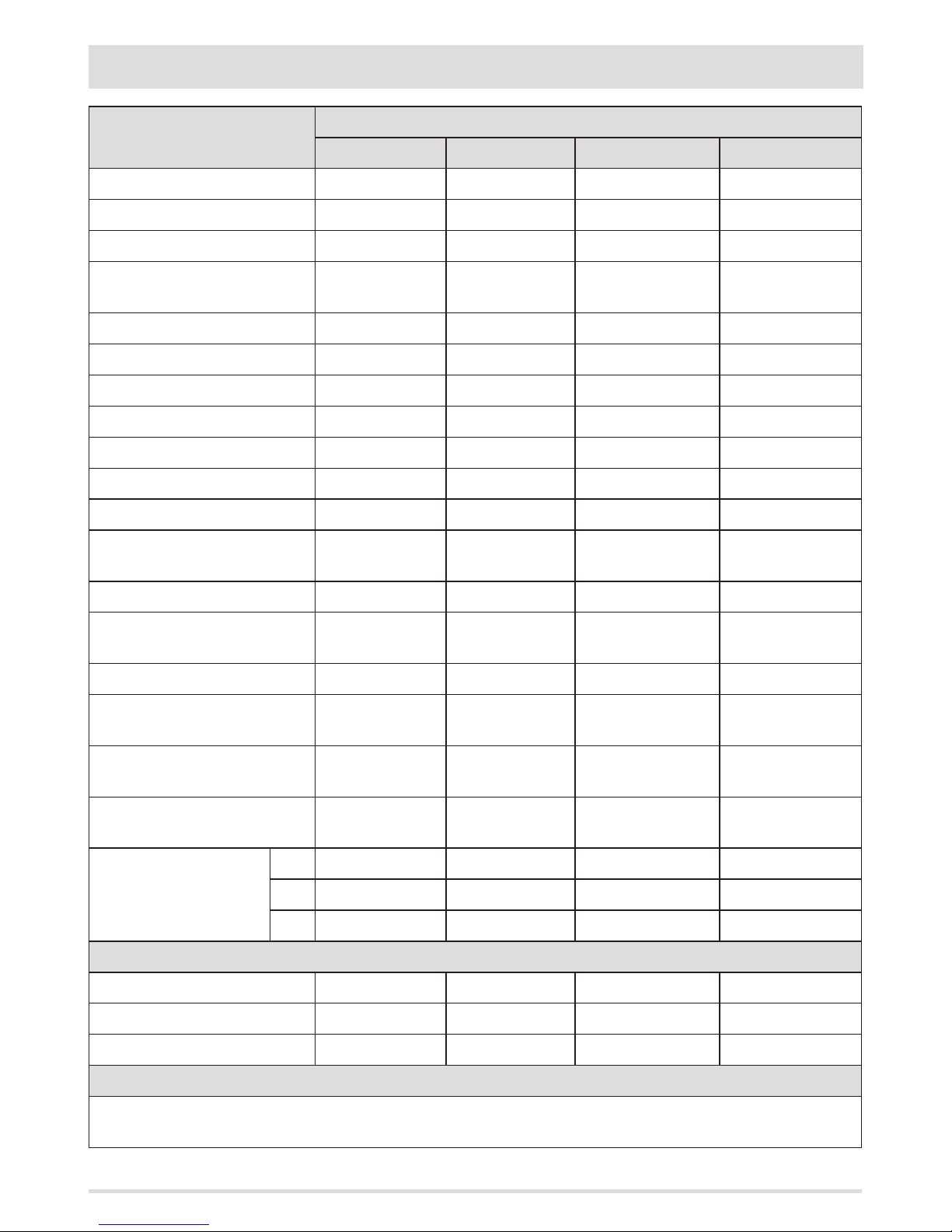
TECHNICAL CHARACTERISTICS
ST.MORITZ
Le06 Le08 Le10 Le12
Type of fuel Wood Wood Wood Wood
Hourly consumption 1.9 kg/h 2.2 kg/h 2.7 kg/h 3.4-1.7 kg/h
Reloading/load time 45 min / 1.4 kg 45 min / 1.7 kg 45 min / 2.0 kg 45 min / 2.6 kg
Nominal output power 7.0 kW (6020
kcal/h)
8.0 kW (6880
kcal/h)
9.5 kW (8170 kcal/h) 12.0 kW (10320
kcal/h)
Minimum power output - - - 6,0 kW (5160 kcal/h)
Eciency 87,5% 85,0% 85,0% 84,5%
CO emission in fumes (13% O2) 0.08% 0.06% 0.05% 0.10%
Particulate/OGC/Nox (13%O2) 11-14-53 mg/Nm3 14-12-54 mg/Nm3 14-12-54 mg/Nm3 27-19-84 mg/Nm3
Smoke mass ow rate 4.7 g/s 6.1 g/s 7.4 g/s 8.8 g/s
Smoke temperature 193°C 205°C 217°C 227°C
Recommended draught 0.12 mbar - 12 Pa 0.12 mbar - 12 Pa 0.12 mbar - 12 Pa 0.12 mbar - 12 Pa
Heatable volume m3 151/40 - 172/35 -
201/30*
172/40 - 197/35 229/30*
204/40 - 233/35 272/30*
258/40 - 295/35 344/30*
Smoke outlet Ø12 cm Ø12 cm Ø15 cm Ø15 cm
Net weight 505 kg (380 kg
stone)
525 kg (395 kg
stone)
573 kg (413 kg stone) 647 kg (460 kg stone)
External air inlet 100 cm2 100 cm2 100 cm2 100 cm2
Distance from ammable material
(back)
300 mm 300 mm 300 mm 300 mm
Distance from ammable material
(side)
400 mm 400 mm 400 mm 400 mm
Distance from ammable material
(underneath)
0 mm 0 mm 0 mm 0 mm
Dimensions
L 520 mm 600 mm 680 mm 760 mm
B 510 mm 510 mm 510 mm 510 mm
H 1200 mm 1200 mm 1200 mm 1200 mm
Flue
Up to 5 m
20x20 cm Ø20 20x20 cm Ø20 20x30 cm Ø22 20x30 cm Ø22
Between 5 and 7 m
18x18 cm Ø18 18x18 cm Ø18 20x20 cm Ø20 20x20 cm Ø20
Beyond 7 m
15x15 cm Ø15 15x15 cm Ø15 18x18 cm Ø18 18x18 cm Ø18
Notes
Intermittent combustion appliance.
*Volume that can be heated based on the power requirement per m3 (respectively 40-35-30 kcal/h per m3)
Tested according to EN 13240 in accordance with European regulation for Construction Products (EU 305/2011).
Page 36
34
3-DIMENSIONS AND TECHNICAL FEATURES
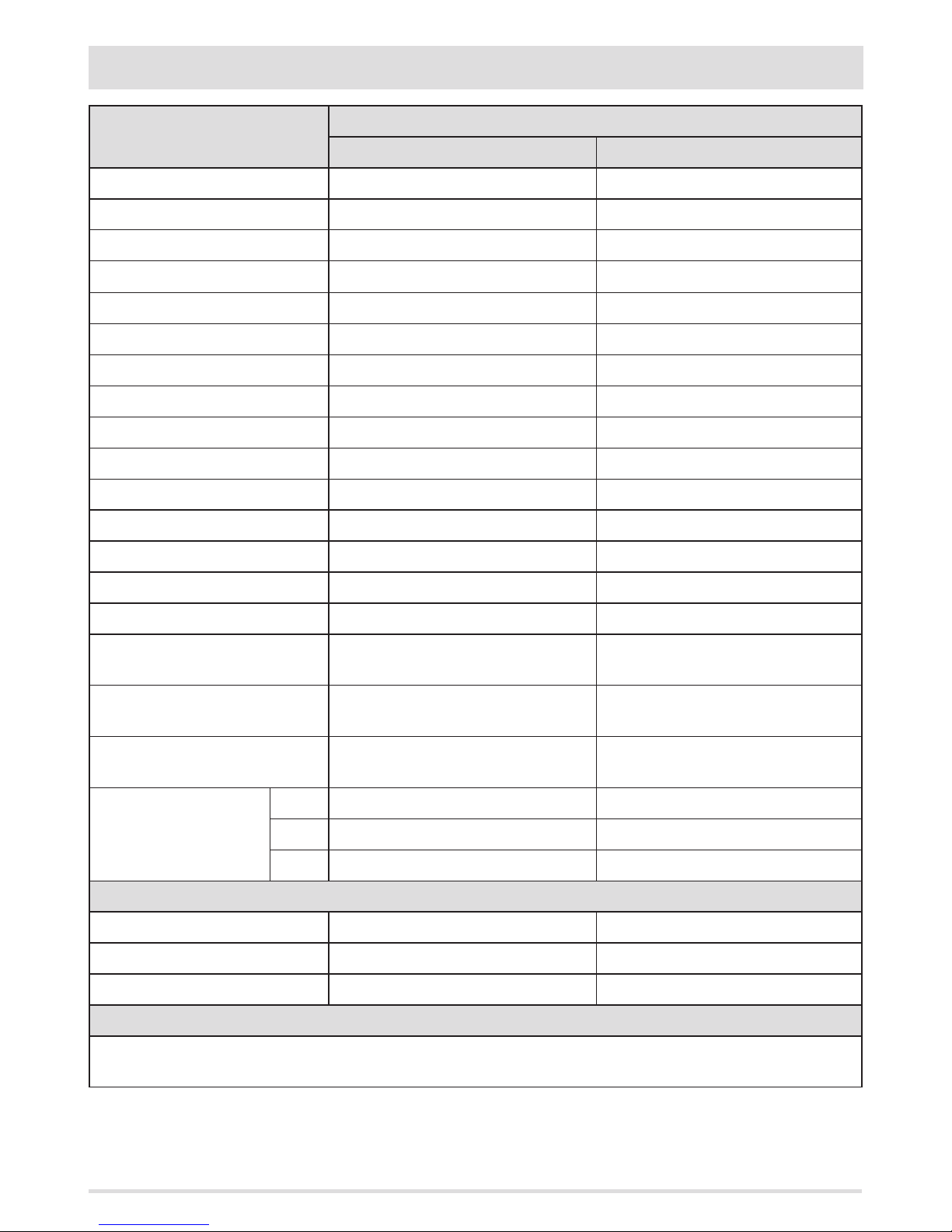
TECHNICAL CHARACTERISTICS
CHAMONIX
Lf10 Le11
Type of fuel Wood Wood
Hourly consumption 3.1 kg/h 2.8 kg/h
Reloading/load time 45 min / 2.3 kg 45 min / 2.1 kg
Nominal output power 10.0 kW (8600 kcal/h) 11.5 kW (9890 kcal/h)
Minimum power output - -
Eciency 75.0% 80.0%
CO emission in fumes (13% O2) 0.21% 0.32%
Particulate/OGC/Nox (13%O2) - -
Smoke mass ow rate 12.4 g/s 8.3 g/s
Smoke temperature 320°C 350°C
Recommended draught 0.12 mbar - 12 Pa 0.12 mbar - 12 Pa
Heatable volume m3 215/40 - 246/35 - 287/30* 247/40 - 283/35 - 330/30*
Smoke outlet Ø15 cm Ø15 cm
Net weight 508 kg (338 kg stone) 508 kg (338 kg stone)
External air inlet 100 cm2 100 cm2
Distance from ammable material
(back)
300 mm 200 mm
Distance from ammable material
(side)
200 mm 200 mm
Distance from ammable material
(underneath)
0 mm 0 mm
Dimensions
L 780 mm 780 mm
B 570 mm 570 mm
H 1340 mm 1060 mm
Flue
Up to 5 m
20x30 cm Ø22 20x30 cm Ø22
Between 5 and 7 m
20x20 cm Ø20 20x20 cm Ø20
Beyond 7 m
18x18 cm Ø18 18x18 cm Ø18
Notes
Intermittent combustion appliance.
* Volume that can be heated based on the power requirement per m3 (respectively 40-35-30 kcal/h per m3)
Tested according to EN 13240 in accordance with European regulation for Construction Products (EU 305/2011).
Page 37
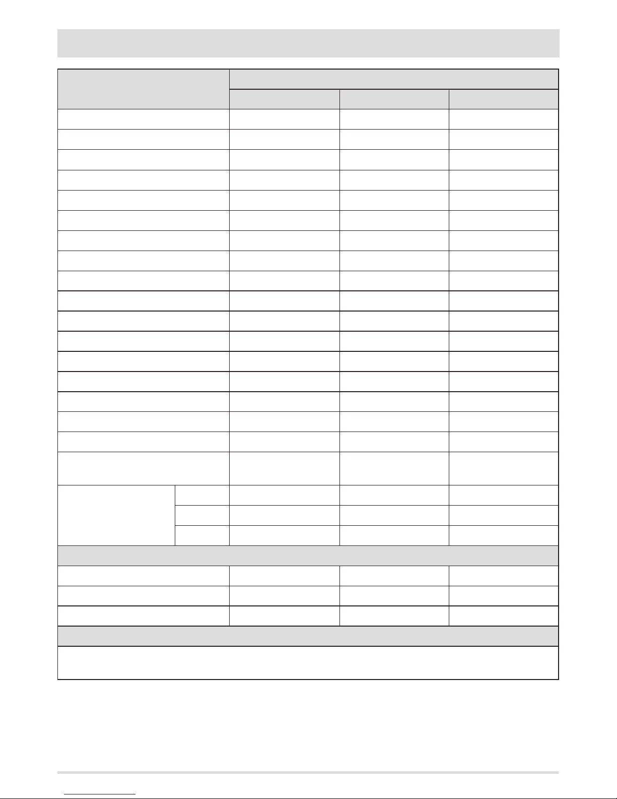
35
3-DIMENSIONS AND TECHNICAL FEATURES
TECHNICAL CHARACTERISTICS
CORTINA
Le09 Le10 Lf11
Type of fuel Wood Wood Wood
Hourly consumption 2.7 kg/h 2.9 kg/h 4.5 kg/h
Reloading/load time 45 min / 2.0 kg 45 min / 2.2 kg 45 min / 3.4 kg
Nominal output power 9.0 kW (7740 kcal/h) 10.0 kW (8600 kcal/h) 11.5 kW (9890 kcal/h)
Minimum power output - - -
Eciency 76.0% 75.5% 77.0%
CO emission in fumes (13% O2) 0.28% 0.21% 0.30%
Particulate/OGC/Nox (13%O2) - - -
Smoke mass ow rate 9.1 g/s 9.1 g/s 11.3 g/s
Smoke temperature 390°C 320°C 365°C
Recommended draught 0.12 mbar - 12 Pa 0.12 mbar - 12 Pa 0.12 mbar - 12 Pa
Heatable volume m3 194/40 - 221/35 - 258/30* 215/40 - 246/35 - 287/30* 247/40 - 283/35 - 330/30*
Smoke outlet Ø12 cm Ø15 cm Ø15 cm
Net weight 151 kg (38 kg stone) 201 kg (44 kg stone) 255 kg (57 kg stone)
External air inlet 100 cm2 100 cm2 100 cm2
Distance from ammable material (back) 300 mm 300 mm 300 mm
Distance from ammable material (side) 300 mm 300 mm 300 mm
Distance from ammable material
(underneath)
0 mm 0 mm 0 mm
Dimensions
L 550 mm 790 mm 630 mm
B 440 mm 450 mm 540 mm
H 1000 mm 1060 mm 1430 mm
Flue
Up to 5 m
20x20 cm Ø20 20x30 cm Ø22 20x30 cm Ø22
Between 5 and 7 m
18x18 cm Ø18 20x20 cm Ø20 20x20 cm Ø20
Beyond 7 m
15x15 cm Ø15 18x18 cm Ø18 18x18 cm Ø18
Notes
Intermittent combustion appliance.
* Volume that can be heated based on the power requirement per m3 (respectively 40-35-30 kcal/h per m3)
Tested according to EN 13240 in accordance with European regulation for Construction Products (EU 305/2011).
Page 38
5
4
3
3
1
1
2
2
4
36
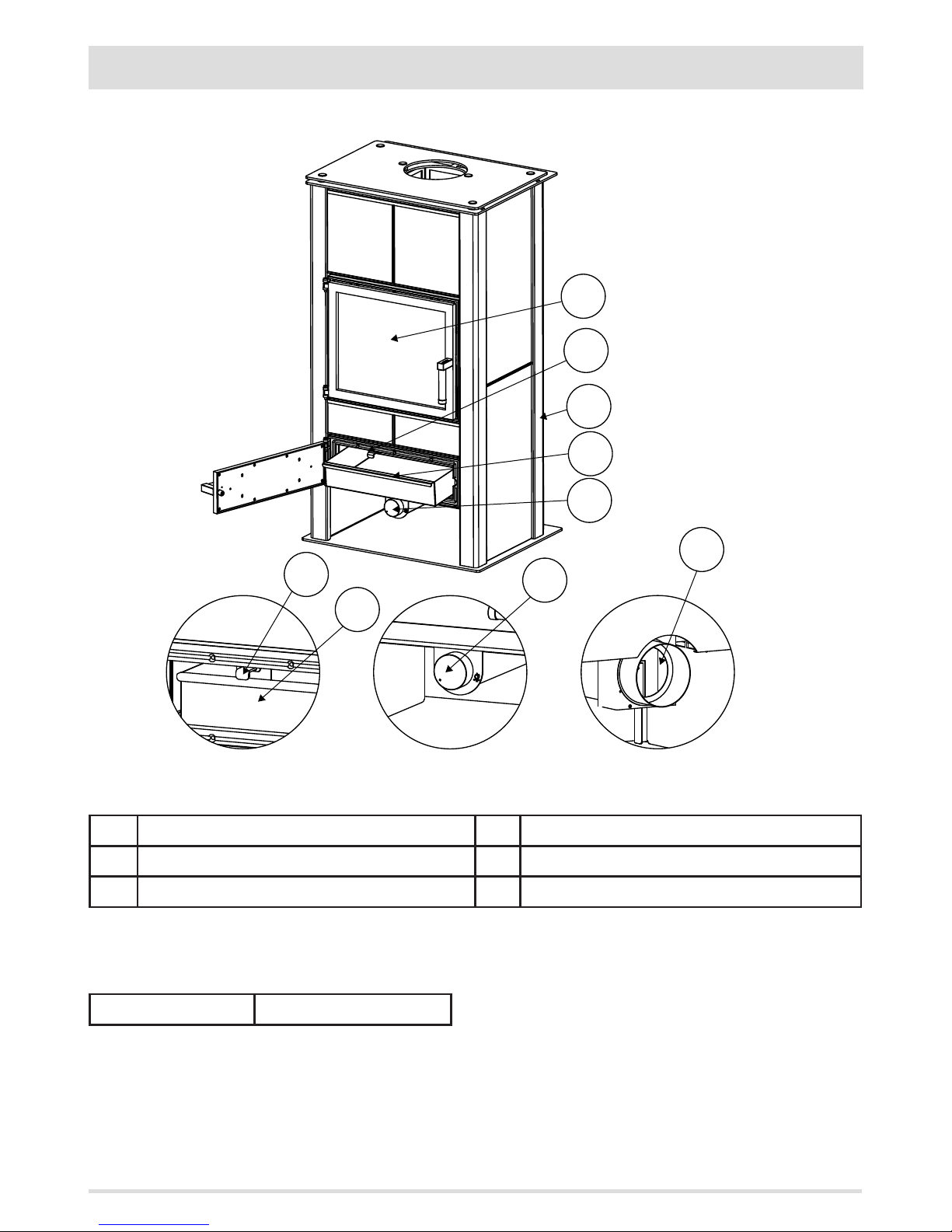
4-DESCRIPTION OF PARTS
ASKO LINE
DESCRIPTION OF ASKO LINE STOVE PARTS
1 PRIMARY COMBUSTION AIR CONTROL 4 ASH SHAKER ROD
2 ASH PAN 5 COMBUSTION CHAMBER
3 PRIMARY COMBUSTION AIR INTAKE Ø100 mm
EQUIPMENT
• POKER • OVEN MITTEN
Page 39
5
4
3
2
1
1
2
3
5
37
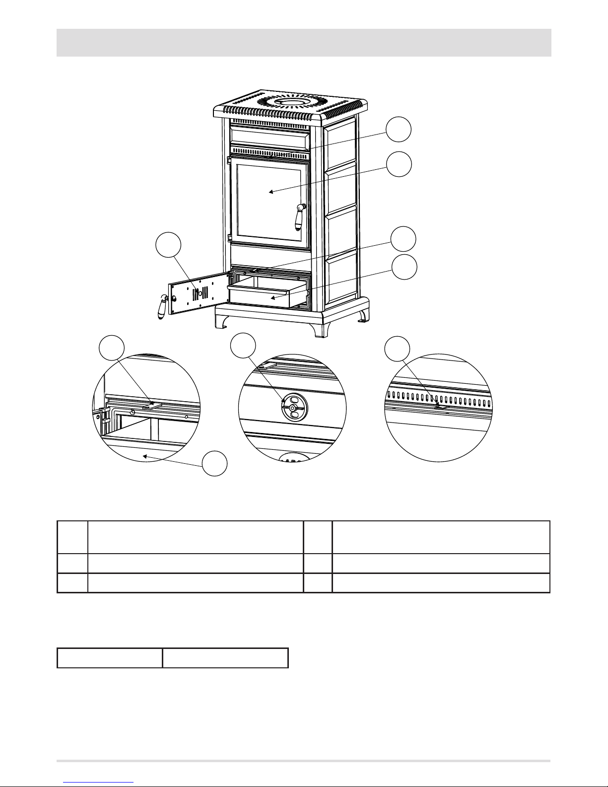
4-DESCRIPTION OF PARTS
CORTINA LINE LE09 LE10
DESCRIPTION OF CORTINA LINE STOVE PARTS
1 PRIMARY COMBUSTION AIR CONTROL AT THE FRONT OF
THE DOOR LEAF
4 COMBUSTION CHAMBER
2 ASH PAN 5 SECONDARY AIR CONTROL FOR GLASS CLEANING
3 ASH SHAKER ROD
EQUIPMENT
• POKER • OVEN MITTEN
Page 40
1
2
3
5
6
5
4
3
2
1
38
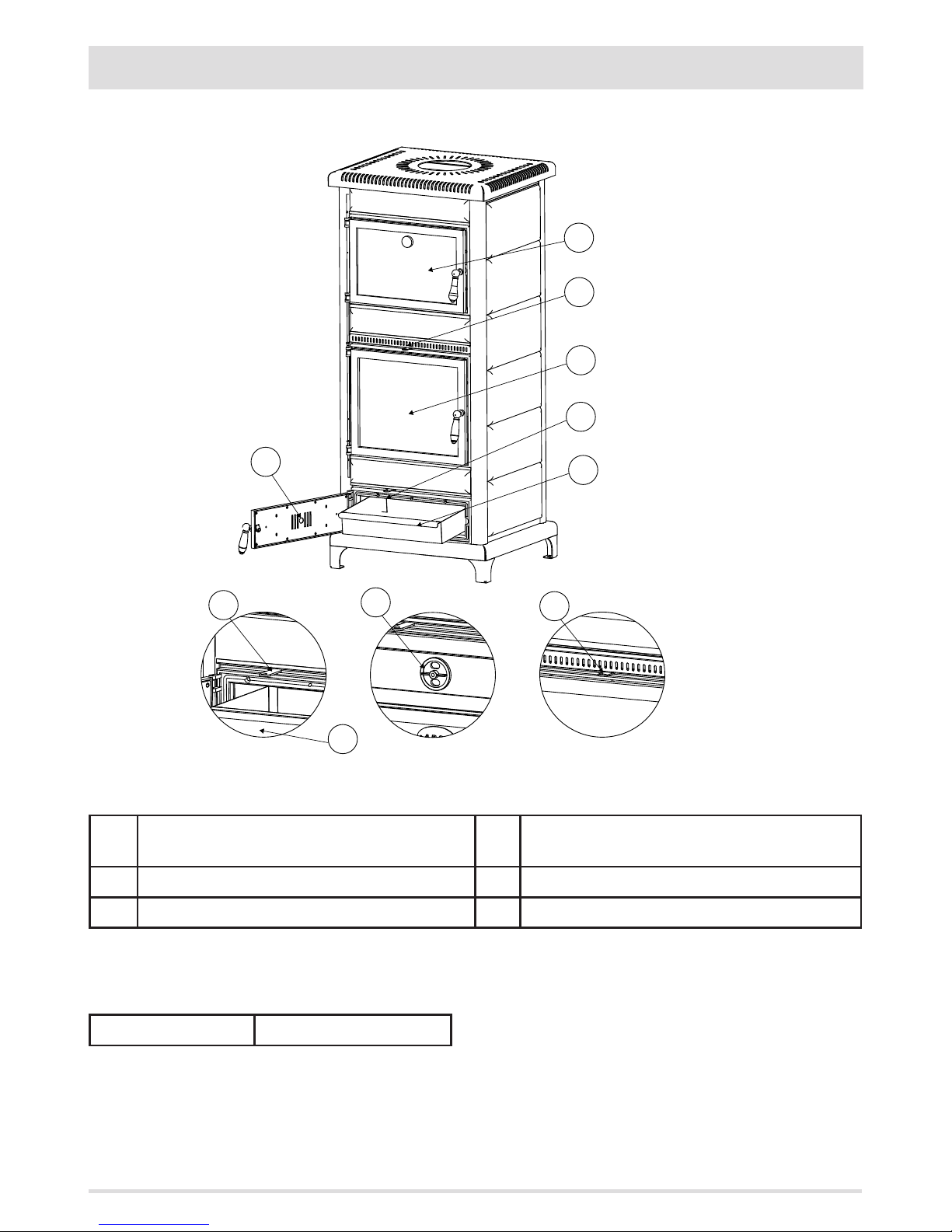
4-DESCRIPTION OF PARTS
CORTINA LINE LF11
DESCRIPTION OF CORTINA LINE STOVE PARTS
1 PRIMARY COMBUSTION AIR CONTROL AT THE FRONT OF
THE DOOR LEAF
4 COMBUSTION CHAMBER
2 ASH PAN 5 SECONDARY AIR CONTROL FOR GLASS CLEANING
3 ASH SHAKER ROD 6 SMALL BAKING OVEN
EQUIPMENT
• POKER • OVEN MITTEN
Page 41
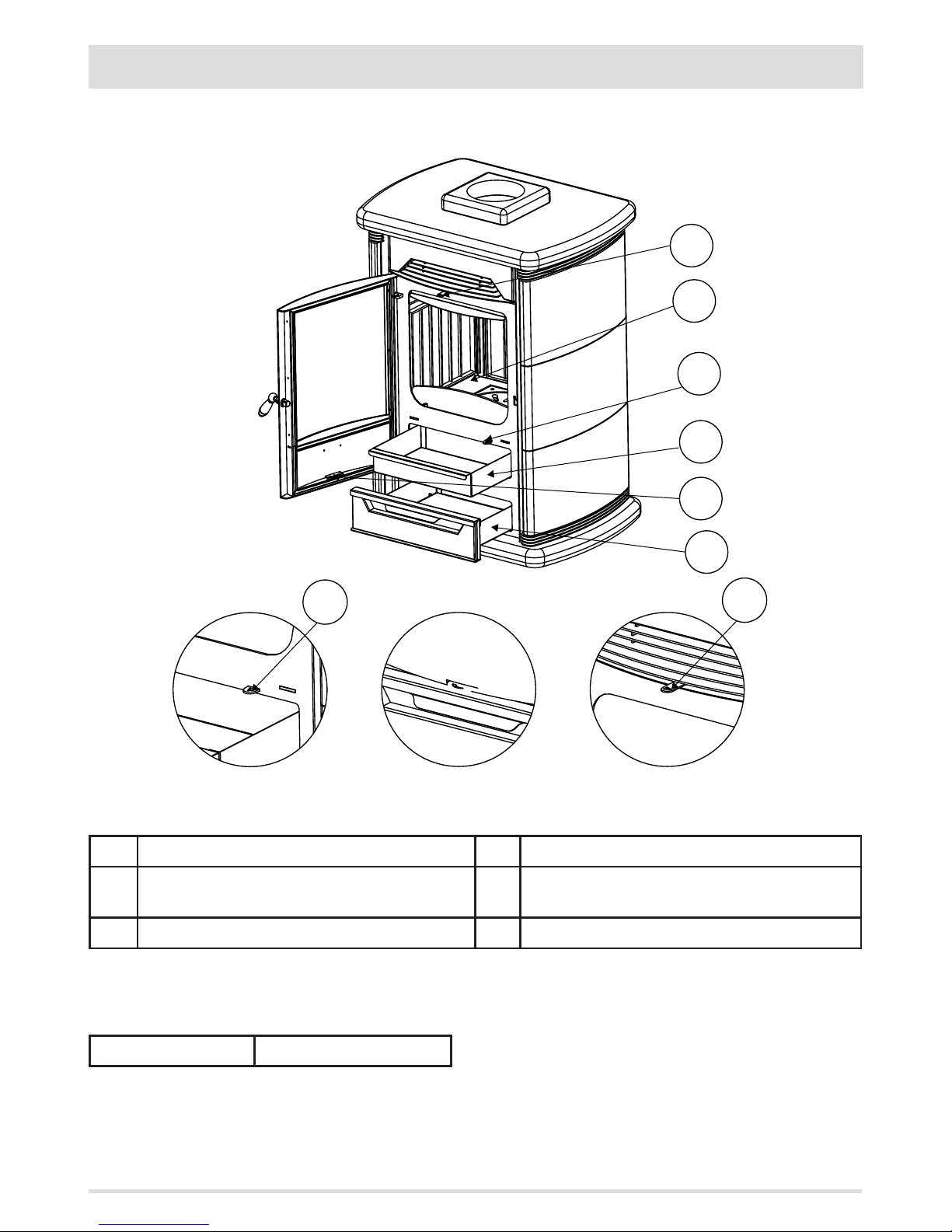
6
5
4
3
2
1
6
4
39
4-DESCRIPTION OF PARTS
CHAMONIX LINE LE11
DESCRIPTION OF CHAMONIX LINE STOVE PARTS
1 STORAGE COMPARTMENT 4 ASH SHAKER ROD
2 PRIMARY COMBUSTION AIR CONTROL AT THE FRONT OF
THE DOOR LEAF
5 COMBUSTION CHAMBER
3 ASH PAN 6 SECONDARY AIR CONTROL FOR GLASS CLEANING
EQUIPMENT
• POKER • OVEN MITTEN
Page 42
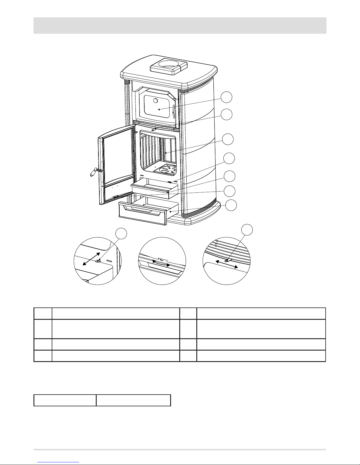
7
6
5
4
3
2
1
6
4
40
4-DESCRIPTION OF PARTS
CHAMONIX LINE LF10
DESCRIPTION OF CHAMONIX LINE STOVE PARTS
1 STORAGE COMPARTMENT 5 COMBUSTION CHAMBER
2 PRIMARY COMBUSTION AIR CONTROL AT THE FRONT OF
THE DOOR LEAF
6 SECONDARY AIR CONTROL FOR GLASS CLEANING
3 ASH PAN 7 SMALL BAKING OVEN
4 ASH SHAKER ROD
EQUIPMENT
• POKER • OVEN MITTEN
Page 43
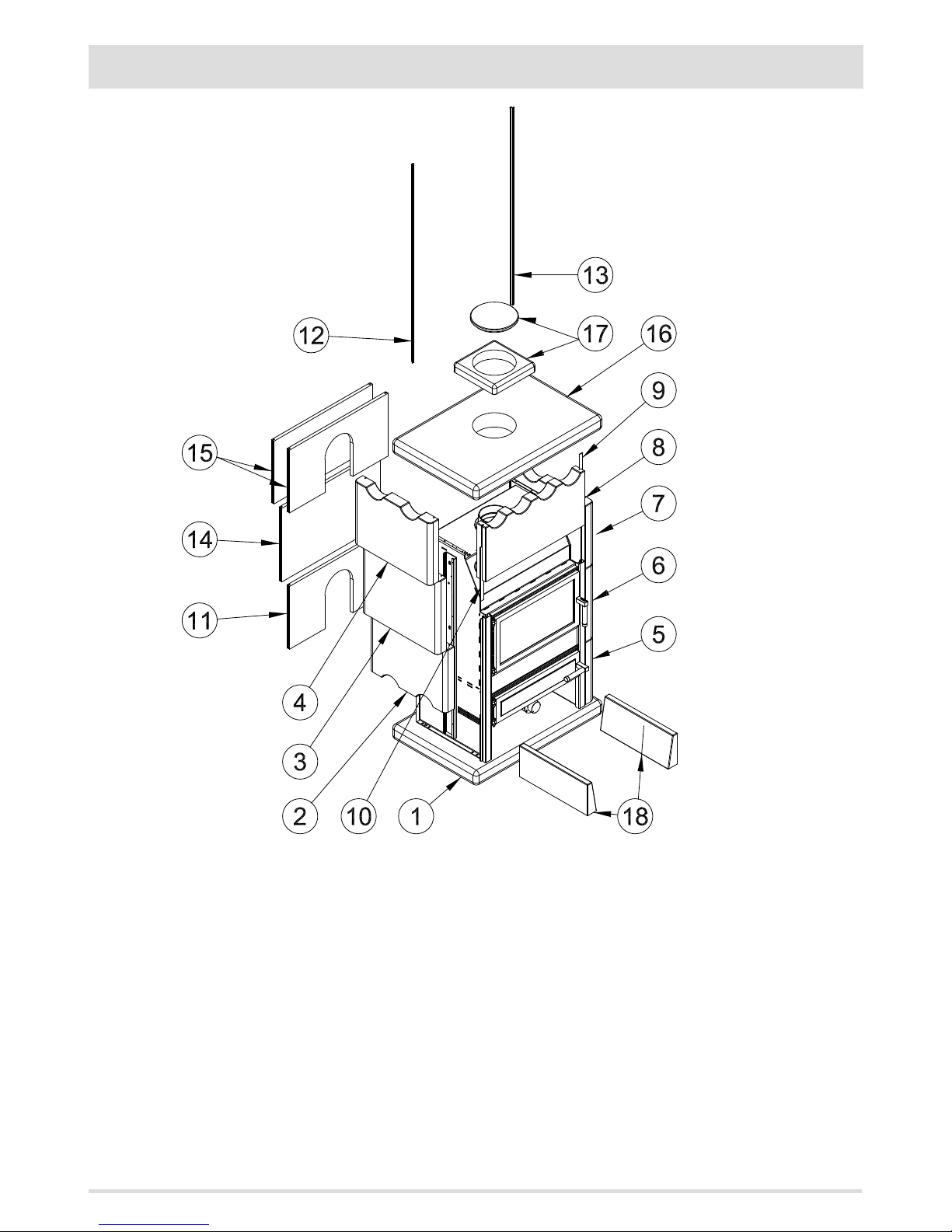
41
5-SERPENTINE STONES ASSEMBLY DIAGRAM
• Position the base (1)
• Place the stove on the base, fasten it with the four pegs supplied and add silicone as needed
• Resume positioning the other stones in progressive order as per drawing above
Page 44
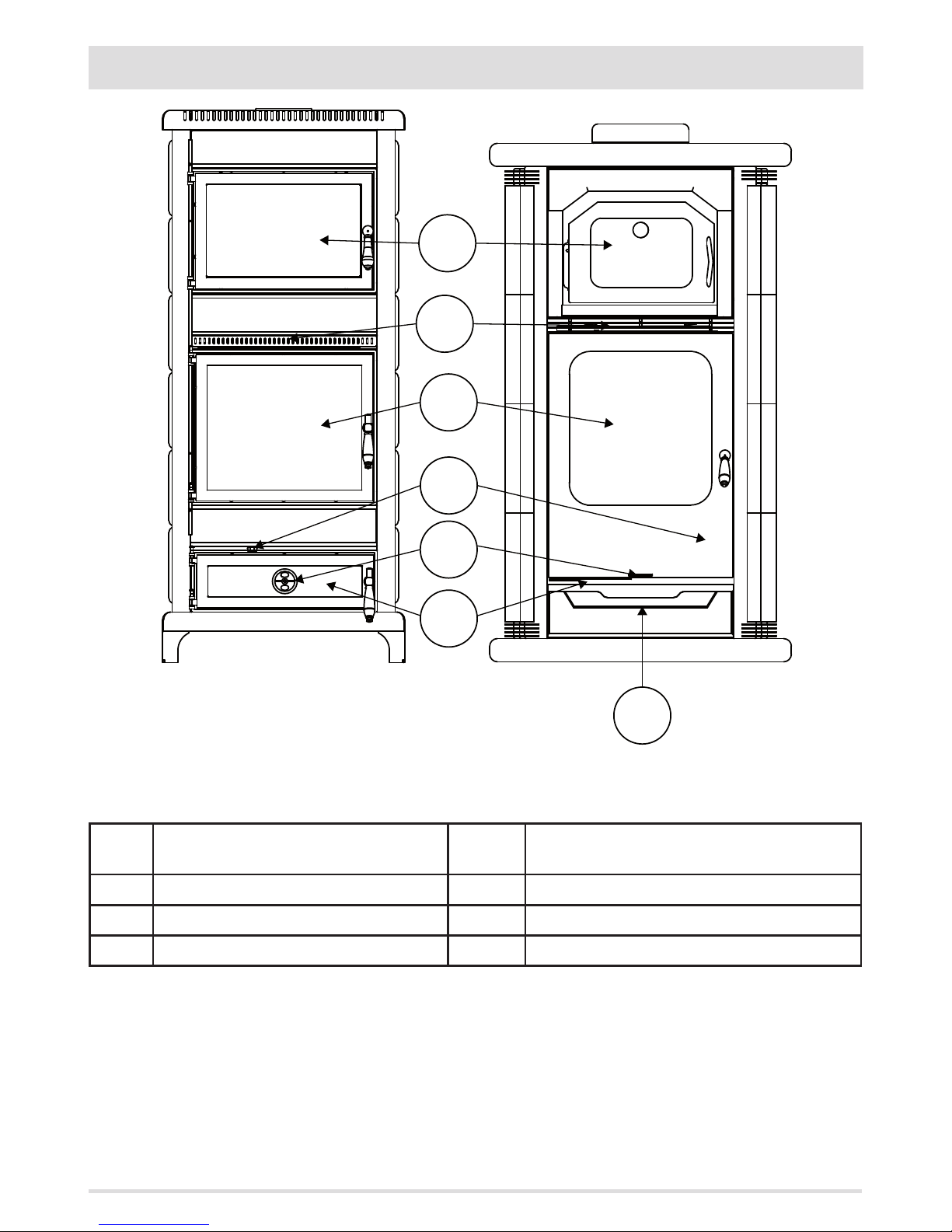
7
6
5
4
3
1
2
42
6-LIST OF PARTS AND OPERATION
1 STORAGE COMPARTMENT - DO NOT INSERT
FLAMMABLE MATERIAL
5 WOOD BURNING FIREBOX
2 ASH PAN 6 SECONDARY COMBUSTION AIR CONTROL LEVER
3 PRIMARY COMBUSTION AIR CONTROL VALVE 7 SMALL BAKING OVEN (WHERE PROVIDED)
4 ASH SHAKER ROD
Page 45
43
6-LIST OF PARTS AND OPERATION
STARTUP
Completely open primary air (3), pull out lever (4) and pull to the left secondary air lever (6).
To start, we recommend using the commercially available solid re lighters placing them at the centre of the grid, on which a small
amount of wooden sticks or twigs of seasoned wood and some small wood logs are placed. Light the re and wait for all the wood to
iname well, therefore heating the ue and its draw. (On certain low pressure days it may be useful to leave the ash pan door (2) ajar
by a few cm to aid lighting). After a few minutes, when combustion is well under way, add some medium sized logs. Wait for the re to
catch well then start closing the primary air damper (3) and the ash shaking lever (4). About 20/30 minutes after lighting, load with large
logs every 3-4 hours on the bed of embers (it may be useful to move lever (6) to the left). This manner of utilisation aords the best yield
(higher than 75% on average) and long duration (continuous re) of combustion.
Note: Do not forget to regularly clean the ash pan.
AVOID BIG FLAMES WHICH CAUSE SERIOUS DAMAGE AND IMMEDIATE REVOCATION OF THE WARRANTY.
OPERATION
The stove is able to provide intermittent combustion.
By adjusting the combustion air with valve (3) and combining it with opening secondary air (6), you can increase or decrease the rate of
combustion and thus adapt the various heating and cooking needs.
WHEN IN OPERATION THE APPLIANCE IS VERY HOT, KEEP CHILDREN AT A DISTANCE USING SUITABLE GUARDS.
Use of wood food warmer where provided
The temperature displayed by the thermometer on the door glazing may certainly help you to heat your dishes.
Smoke distribution on all surfaces of the food warmer results in consistent temperature in its body. We recommend not letting the
temperature go above 250°C, because you run the risk of quickly burning the food to be warmed.
Page 46

44
9-MAINTENANCE AND CLEANING
All the cleaning operations of all parts must be performed with the product completely cold and the plug
disconnected.
CLEANING UNDER THE USER'S RESPONSIBILITY
CLEANING PRODUCTS
The stainless steel nishes and the coloured details if not handled with care and with specic products may deteriorate beyond repair.
The fumes produced by some chemicals can create an aggressive cloud which can dull the nishes of the cooker such as the steel and the
coloured panels, resulting in stains on the nishes similar to rust stains.
The occurrence of these stains will totally invalidate the product warranty.
CLEANING INSIDE THE FOOD WARMER COMPARTMENT
Let the food warmer compartment cool down and clean it thoroughly with a damp cloth soaked in warm water and non-abrasive
detergent (or appropriate products on the market).
Do not use abrasive cloths or sponges or other products that could irreparably scratch the enamel.
ROUTINE CLEANING OF FURNACE AND ASH DRAWER
With cold stove it is advisable before ring to thoroughly clean the brazier by removing the ash and any unburned parts.
It is advisable to empty the ash collected in the ash pan underneath the rebox as well, ensuring there are no hot embers.
It is recommended to remove the ashes in the tray every 8 hours of operation. The maximum lling height of the hearth is half the height
of the combustion chamber.
STOVE CLEANING SMOKE SIDE
The smoke side of the stove must be cleaned whenever you notice any diculty in lighting, combustion problems, tendency of smoke
leaking out of the loading door which was not encountered beforehand. On average, it can be assumed that a properly installed stove,
loaded with well seasoned wood needs to be cleaned about every two months (depending also on the length of the connecting pipes and
the number of elbows tted). To clean the connecting pipes and the inside of the stove, use brushes or other appropriate tools so as not
to scratch and therefore damage enamelled or painted parts. Stoves with food warmer compartment are designed so that soot normally
drops into the hearth. In other stoves it is required to lift up and shake the stainless steel bae located above the hearth so any ash or
soot drops into it.
In the event that the top plate is opened at the time of retting it is well to replace the gasket.
The smoke duct and ue must be regularly cleaned. Check that these ducts aren't blocked following an extended period of inactivity.
OUTER CLEANING
Occasionally rub a cloth slightly moistened with warm water on the painted parts, on ceramics and majolicas. The ceramic glass must
be cleaned with suitable liquids or sprays either purchased or supplied by us. Any traces of food or stains on the radiating plate must be
removed with normal detergents, wire wool or similar for the hardest ones, then rub the plate with a cloth soaked in cooking oil.
In the event of deterioration of door painting or black-painted trims, only use silicone varnishes resistant to high temperatures for
touching up and only with stove unlit.
For stone panels or plates it is recommended to use steam appliances with a cloth.
WHEN IN OPERATION THE APPLIANCE IS VERY HOT, KEEP CHILDREN AT A DISTANCE USING SUITABLE GUARDS.
AVOID BIG FLAMES WHICH CAUSE SERIOUS DAMAGE AND IMMEDIATE REVOCATION OF THE WARRANTY.
Page 47

Page 48

20/03/2015REV.08901503800
CORRADI CUCINE S.r.l.
Registered oce
Via La Croce n°8
33074 Vigonovo di Fontanafredda (PN) – ITALY
Internet: www.jcorradigroup.it
e-mail: [email protected]
 Loading...