

Page 1
Service Manual
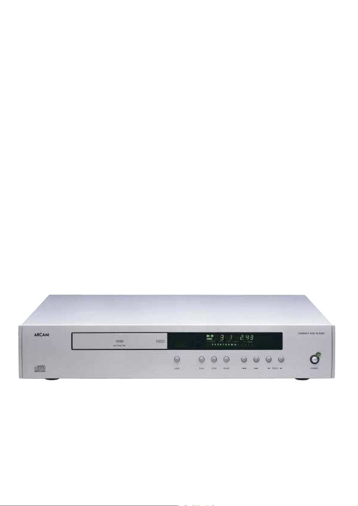
CD72/92
DiVA CD72, CD92
Compact Disc Player
Issue 1.0
ARCAMARCAM
Page 2

Contents List
!
Contents list
!
Circuit description
!
Upgrade procedure
!
Service guide
!
Circuit diagrams
!
Component overlays
!
Circuit board parts list
!
General assembly parts list
Page 3

CD72/CD92 Circuit Description
SUMMARY
The Main PCB for the DiVA CD72/92 player may be built as
two different versions:
! With all components fitted for the Alpha CD72
(L887RS)
! With audio components and connectors omitted, for
use as a motherboard for plug-in DAC module L816
(L888RS) for CD92
The CD72 version may be converted for use with a upgrade
plug-in DAC board by removing a configuration connector.
The system is based on a Sony kit, comprising CDM14-5BD10
laser mechanism & loader, micro-controller and fluorescent
display.
The PCM 1716, as per the 1710, can be operated in either
Software or Hardware mode. The default for the CD72 is
hardware mode.
Power Supplies & Reset/Mute
Selection for 230V or 115V mains operation is made by
inserting a fuse into the appropriate position. The mains
transformer has three secondary windings:
1. Provides +12V and -12V supplies for the audio
output circuitry via regulators Z204 and Z205.
2. This produces the digital, motor drive and
fluorescent display grid supplies:
+7.3V (Z206) Mechanism and motor driver supply
+5V (Z208) General digital logic supply
+5V (Z207) Supply to DAC
+5V (Z203) Supply to system clock generator
-30V (Z209) Display grid voltage.
3. Provides an AC supply for the display filament.
The power-on reset signal XRST is generated by R17 and C29.
When the power switch is turned off one of its poles discharges
C29 quickly. This, along with the AMUTE signal from the
micro, controls the output mute transistors via level shifter Q3.
Remote Control/PIC Micro
The PIC micro controller converts the RC-5 format data into the
NEC format required by the Sony micro. The PIC also controls
the configuration of the digital filter/DAC on the DAC board.
Micro controller & Display Board
The system micro controller Z212 has the following functions:
! Control of the mechanism & decoder on the CDM14
! Control of mute, attenuation and deemphasis for the
DAC
! Direct drive of the fluorescent display
! Remote control decoding
! Keyboard scanning
The keyboard scanning works by connecting the keys to a
resistor ladder on an ADC input to the micro. Pressing a key
presents a unique voltage to this input.
The remote control data contains a ‘ Customer Code’ that
identifies this as an Arcam product. The diode network D291 to
D297 configures the micro to accept this code.
Motor Driver
The status of the drawer is indicated to the micro by two micro
switches ‘ INSW’ and ‘ OUTSW’ on SK205. The micro controls
the drawer motor via driver Z210.
DAC & System Clock
The DAC is a Burr Brown PCM1716. Mute, attenuation and deemphasis functions can be controlled via a 3-wire serial link
from the system micro to pins 26, 27 & 28 via resistors R31 R32
& R33 respectively. Currently resistors R31 to R33 are not
fitted and the DAC is configured for hardware control.
Digital audio is input on pins 1, 2 & 3 in standard Sony format,
i.e. Word Clock, Bit Clock and Data.
The system clock is based around 16.9344 MHZ crystal X1 and
transistor Q2. This produces a stable clock with low jitter.
Z202E & D provide amplification and buffering to the DAC.
Analogue Filters
Z1A (& Z101A) provides the basis for a 2-pole filter. Z1B (&
Z101B) buffer the audio and set the output level.
Digital Output
An SPDIF format digital output signal is generated by the
decoder on the mechanism assembly. This is passed through
isolating transformer T202 to a single phono socket SK5.
Optical digital output via Z2 is also tapped off the digital output
signal. Power is supplied to Z2 via Z3 a 78L05 regulator.
Upgrade to CD92
The CD72 includes a configuration PCB connected to PL1. This
provides power to the DAC and clock generator, connects the
digital audio and system clock signals to the DAC and provides
additional clock buffering with Z4 A&B .
Removing this board removes these connections and allows the
system clock generated on the DAC board to pass through to the
CDM14.
Page 4

Upgrading a CD72 to CD92
1. Disconnect the mains supply from the DiVA CD player.
2. Remove the top cover by taking out the 2 screws from the top edge of the rear
panel (marked 1) and on each side (marked 2).
3. Pull off the sticky plastic gasket between the digital output socket and the
audio output sockets to reveal the 4 audio output socket holes through which
the DAC board sockets will pass.
4. Any remnants of adhesive can be removed by rubbing it gently with your
finger and rolling it off. We do not recommend the use of solvents.
5. Fit the 2 supplied PCB (printed circuit board) pillars to the holes in the main
board on either side of the flexfoil coming from the display board. These are
marked 3 on the drawing overleaf. The big end of the PCB pillars goes into
the main PCB. These push in and clip home. Take great care not to damage
the main circuit board.
6. Remove the Configuration Module (the small vertically mounted PCB in the
centre of the main board). It will not be needed once the new DAC board is
fitted.
7. Note: The original nickel plated audio output sockets are no longer connected
after the upgrade and cannot be used. However the digital output still
functions.
8. Remove the following jumpers :- PL2, PL3, PL4, PL6. Fit the following
jumpers :- PL5, PL7.
9. Fit the magnetic shielding plate, by peeling off one side of (E923MC the
adhesive pad) and stick to (E922MC the shielding plate). Then peel the
backing off the other side of pad & Align the top edge with the top of the
transformer and fit centrally. It MUST align with the top edge of the
transformer, if it is fitted to low to the board it may cause shorting.
10. Take static precautions first. With the aluminium extrusion of the DAC
module uppermost fit the flexfoils from the module in to the appropriate
sockets in the main board, ensuring they are pushed fully home. If they are
not pushed fully home, the unit may not read discs. You may find it helps to
slide the module into the unit so that the audio output sockets fit through the
holes in the rear panel and angle the module slightly upwards to achieve this.
11. Push the module down firmly on to the support pillars.
12. Fit the supplied screws with integral washers to the 3 points marked 4 on the
drawing overleaf to secure the module in place. The 2 slightly shorter screws
and the shake proof washers should be fitted to the 2 points marked 6.
13. Refit the top cover, connect the unit to live mains and switch on. Press load to
allow the tray to come fully out and then remove the mains lead from the unit.
Remove the draw front and fit the new draw front with the CD92 / HDCD
logo on.
14. Check the unit functions correctly and if you have an HDCD disc check that a
red glow is seen behind the display window when it is playing.
Page 5

Upgrading a CD72 ( TEXT ) to CD92 ( TEXT )
1. Disconnect the mains supply from the DiVA CD player.
2. Remove the top cover by taking out the 2 screws from the top edge of the rear
panel (marked 1) and on each side (marked 2).
3. Pull off the sticky plastic gasket between the digital output socket and the
audio output sockets to reveal the 4 audio output socket holes through which
the DAC board sockets will pass.
4. Any remnants of adhesive can be removed by rubbing it gently with your
finger and rolling it off. We do not recommend the use of solvents.
5. Fit the 2 supplied PCB (printed circuit board) pillars to the holes in the main
board on either side of the flexfoil coming from the display board. These are
marked 3 on the drawing overleaf. The big end of the PCB pillars goes into
the main PCB. These push in and clip home. Take great care not to damage
the main circuit board.
6. Note: The original nickel plated audio output sockets are no longer connected
after the upgrade and cannot be used. However the digital output still
functions.
7. Set the main board jumper settings as listed below :-
PL200 ON
PL201 ON
PL202 ON
PL203 OFF
PL204 ON
PL205 OFF
PL300 2 and 3
PL400 OFF
PL401 OFF
PL402 OFF
8. Fit the magnetic shielding plate ( part no E922MC ) to the adhesive pad ( part
no E923MC).
Peel the backing off the other side of the mains transformer. Align the top
edge with the top of the transformer and fit centrally.
9. Take static precautions first. With the aluminium extrusion of the DAC
module uppermost fit the flexfoils from the module in to the appropriate
sockets in the main board, ensuring they are pushed fully home. If they are
not pushed fully home, the unit may not read discs. You may find it helps to
slide the module into the unit so that the audio output sockets fit through the
holes in the rear panel and angle the module slightly upwards to achieve this.
Page 6

10. Push the module down firmly on to the support pillars.
11. Fit the supplied screws with integral washers to the 3 points marked 4 on the
drawing overleaf to secure the module in place. The 2 slightly shorter screws
and the shake proof washers should be fitted to the 2 points marked 6.
12. Refit the top cover, connect the unit to live mains and switch on. Press load to
allow the tray to come fully out and then remove the mains lead from the unit.
Remove the draw front and fit the new draw front with the CD92 / HDCD
logo on.
13. Check the unit functions correctly and if you have an HDCD disc check that a
red glow is seen behind the display window when it is playing
3
2
2
1
4
6
Page 7

CD72 / CD92 Service Guide
Fault diagnostics
Fault Action
No power Check mains fuse
Check power supply rails
No Audio output Check for digital output, if ok then
check power supply voltages
Check DAC chip
Intermittent noise on output Check Dac chip
Fails to respond to commands Check supply to remote circuit
Check remote flex foil cable
Check for +4.9volts on RX201 o/p
Fails to read disc Check mech supply
Check clock signal
Laser optic moves to end stop
position
No Display Check filament voltage 3.1vac
Spurious display readout Check for dry joints on display board
Power supply test points
Position Voltage
DGND 0 volts
PL6 +12 volts
PL3 -12 volts
R65 +11 volts
Z206 o/p +7.3 volts - mech supply
Z207 o/p +5 volts - DAC supply
Z208 o/p +5 volts
Z209 o/p -30 volts
SK291 across pins 1 and 32 3.1 volts AC – display filament
Hints & tips
!
When upgrading from CD72 to CD92 remember to fit the steel plate to the transformer, this
reduces noise.
!
The CDM14 mech ( part no. B2009 ) is interchangeable between the Alpha7 series and the
DiVA CD72/92 non text version.
!
Please note that the CD72/92 TEXT units use a different mech ( part no. B2012 ), the display
and main boards are also different and therefore are not interchangeable parts.
!
Voltage conversion 230/115VAC by changing the internal fuse position and fitting the correct
rated fuse. 100VAC requires a different transformer.
Caused by failure of clock signal to
the mech
Check mech supply
Check clock signal
Check flex foil cable
Check for dry joints on micro and
display
Page 8

7654321
LK1
LK2
D
C
LINK10NP
LK11
LINK10NP
LK21
LINK10NP
LK31
LINK10NP
LK41
LINK10NP
LK51
LINK10NP
LK61
LINK10NP
LK71
LINK10NP
LK81
LINK10NP
LK91
LINK10NP
LK108
LINK10NP
PCB
LINK10NP
LK119
LINK10NP
LK22
LINK10NP
LK42
LINK10NP
LK52
LINK10NP
LK62
LINK10NP
LK72
LINK10NP
LK82
LINK10NP
LK92
LINK10NP
LK109
LINK10NP
PCB
L887PB_2
B
TL1
TOOLING3.0
LK3
LINK10NP
LK13
LINK10NP
LK23
LINK10NP
LK33
LINK10NP
LK43
LINK10NP
LK53
LINK10NP
LK63
LINK10NP
LK73
LINK10NP
LK83
LINK10NP
LK93
LINK10NP
LK110
LINK10NP
DD2
A2 Vertical
Paper Marker
DD_A2V
DD3
A2 Horizontal
Paper Marker
DD_A2H
LK4
LINK10NP
LK120
LINK10NP
LK44
LINK10NP
LK54
LINK10NP
LK64
LINK10NP
LK74
LINK10NP
LK94
LINK10NP
LK111
LINK10NP
Links
DD5
PCB MATERIAL
CEM1, 2 OZ Cu
CEM1_20Z
Documentation
TL3
TOOLING3.0
Tooling Holes & Alignment Marks
F4
T160MASP
Spare Fuse
LK5
LINK10NP
LK15
LINK10NP
LK25
LINK10NP
LK35
LINK10NP
LK55
LINK10NP
LK65
LINK10NP
LK75
LINK10NP
LK85
LINK10NP
LK95
LINK10NP
TL4
TOOLING3.0
LK6
LINK10NP
LK16
LINK10NP
LK46
LINK10NP
LK56
LINK10NP
LK118
LINK10NP
LK76
LINK10NP
LK86
LINK10NP
LK96
LINK10NP
PS
Photo Strip
PHOTO_STRIP
A2
Update Box
UPDATE_BOX
TL5
TOOLING3.0
EL1
LCD CHAIR
LK7
LINK10NP
LK17
LINK10NP
LK37
LINK10NP
LK47
LINK10NP
LK57
LINK10NP
LK67
LINK10NP
LK77
LINK10NP
LK87
LINK10NP
LK97
LINK10NP
EL2
LCD CHAIR
LK8
LINK10NP
LK18
LINK10NP
LK28
LINK10NP
LK38
LINK10NP
LK58
LINK10NP
LK68
LINK10NP
LK78
LINK10NP
LK88
LINK10NP
LK98
LINK10NP
TL6
TOOLING_OPT
LK9
LINK10NP
LK19
LINK10NP
LK29
LINK10NP
LK39
LINK10NP
LK49
LINK10NP
LK59
LINK10NP
LK69
LINK10NP
LK79
LINK10NP
LK89
LINK10NP
LK99
LINK10NP
FD_1
FIDUCIAL
FD_3
FIDUCIAL
LK10
LINK10NP
LK130
LINK10NP
LK30
LINK10NP
LK40
LINK10NP
LK50
LINK10NP
LK60
LINK10NP
LK70
LINK10NP
LK80
LINK10NP
LK90
LINK10NP
LK107
LINK10NP
LK117
LINK10NP
FD_2
FIDUCIAL
FD_4
FIDUCIAL
LK133
LINK10NP
LK135
LINK10NP
LK126
LINK10NP
LK127
LK121
LINK10NP
LINK10NP
LK122
LINK10NP
LK123
LINK10NP
LK124
LINK10NP
LK125
LINK10NP
LK132
LINK10NP
LK136
LINK10NP
Alpha 7 CD Configuration Plug
SK2
1 2
3 4
5 6
7 8
9 10
11 12
13 14
15 16
DIL16 HSKT
R67
47R MF
L887C3_2
L887C3_2.SCH
L887C2_2
L887C2_2.SCH
INOUT
FILA
FILB 4MHZ
Z4A
1 2
74HC14
+
C1000
10U EL
C58
100N CD
DEEM
SMUTE
AMUTE
RMIN
PGML
CLK
DATA
SCOR
SQCK
XRST
LDON
XLT
SENSE
SUBQ
LDIN
LDOUT
Z4B
3 4
74HC14
14
Z4G
7
74HC14
R68
330R MF
L887C4_2
L887C4_2.SCH
DEEM
SMUTE
AMUTE
RMIN
PGML
CLK
DATA
SCOR
SQCK
XRST
LDON
XLT
SENSE
SUBQ
LDIN
LDOUT
4MHZ
Z4C
5 6
74HC14
K0
K1
K0
K1
FILB
FILA
INOUT
Z4D
74HC14
Ground decoupling
Z4E
89
74HC14
8
D
C
B
1011
Z4F
1213
74HC14
FOR ROS PROGRAMME INCLUDE A7 FOR ALPHA 7 CD
A
1 2 3 4 5 6 7 8
DRAWING TITLE
CD72, CD92 Project Sheet
A & R Cambridge Ltd.
Pembroke Avenue
Denny Industrial Centre
Waterbeach
Cambridge CB5 9PB
Notes:
Filename
G:\DATA\ECO\ECO AGENDA\00_1093 L887PB_2\L887_2\L887_2.ddb - L887c1_2.prj
Circuit Diagram
00_1093 2
00_1083
-
ECO No.
Date Printed
CW 11-10-00 TRACKS MOVED TO CLEAR PILLARS & C64 ADDED FOR EMC
CL 15-09-00 EARTH LINK 8M101 ADDED 1.1
CL 03-08-00 PRODUCTION RELEASE 1
CL 13-07-00 REVISIONS B
WF 07-04-00 A
INITIALS
DAT E
NEW PROTOTYPE
Drawn by:
CW12-Oct-2000
DESCRIPTION OF CHANGE
1 4Sheet of
DRAWING NO.
L887C1_2
A
ISSUE
 Loading...