

Page 1
Installation, and Customization Manual
NetShelter™ SX Networking Cabinet
AR3140
AR3340
AR3347
990-3548D-001
Publication Date: December 2019
Page 2

APC by Schneider Electric Legal Disclaimer
The information presented in this manual is not warranted by APC by Schneider Electric to be authoritative,
error free, or complete. This publication is not meant to be a substitute for a detailed operational and site
specific development plan. Therefore, APC by Schneider Electric assumes no liability for damages, violations of
codes, improper installation, system failures, or any other problems that could arise based on the use of this
Publication.
The information contained in this Publication is provided as is and has been prepared solely for the purpose of
evaluating data center design and construction. This Publication has been compiled in good faith by APC by
Schneider Electric. However, no representation is made or warranty given, either express or implied, as to the
completeness or accuracy of the information this Publication contains.
IN NO EVENT SHALL APC BY SCHNEIDER ELECTRIC, OR ANY PARENT, AFFILIATE OR SUBSIDIARY
COMPANY OF APC BY SCHNEIDER ELECTRIC OR THEIR RESPECTIVE OFFICERS, DIRECTORS, OR
EMPLOYEES BE LIABLE FOR ANY DIRECT, INDIRECT, CONSEQUENTIAL, PUNITIVE, SPECIAL, OR
INCIDENTAL DAMAGES (INCLUDING, WITHOUT LIMITATION, DAMAGES FOR LOSS OF BUSINESS,
CONTRACT, REVENUE, DATA, INFORMATION, OR BUSINESS INTERRUPTION) RESULTING FROM,
ARISING OUT, OR IN CONNECTION WITH THE USE OF, OR INABILITY TO USE THIS PUBLICATION OR
THE CONTENT, EVEN IF APC BY SCHNEIDER ELECTRIC HAS BEEN EXPRESSLY ADVISED OF THE
POSSIBILITY OF SUCH DAMAGES. APC BY SCHNEIDER ELECTRIC RESERVES THE RIGHT TO MAKE
CHANGES OR UPDATES WITH RESPECT TO OR IN THE CONTENT OF THE PUBLICATION OR THE
FORMAT THEREOF AT ANY TIME WITHOUT NOTICE.
Copyright, intellectual, and all other proprietary rights in the content (including but not limited to software, audio,
video, text, and photographs) rests with APC by Schneider Electric or its licensors. All rights in the content not
expressly granted herein are reserved. No rights of any kind are licensed or assigned or shall otherwise pass to
persons accessing this information.
This Publication shall not be for resale in whole or in part.
Page 3

Table of Contents
Introduction ................................................................................................ 1
Important Safety Information.................................................................... 2
Safety Instructions for the NetShelter SX Networking Cabinet . . . . . . . . . 3
Labels . . . . . . . . . . . . . . . . . . . . . . . . . . . . . . . . . . . . . . . . . . . . . . . . . . . . . . . 3
Component Identification.......................................................................... 4
Hardware Bag . . . . . . . . . . . . . . . . . . . . . . . . . . . . . . . . . . . . . . . . . . . . . . . . . 5
Required Tools (not provided) . . . . . . . . . . . . . . . . . . . . . . . . . . . . . . . . . . . 5
Airflow Management Kit . . . . . . . . . . . . . . . . . . . . . . . . . . . . . . . . . . . . . . . . 5
Preparation ................................................................................................. 6
Move the Cabinet . . . . . . . . . . . . . . . . . . . . . . . . . . . . . . . . . . . . . . . . . . . . . . 6
Level the Cabinet . . . . . . . . . . . . . . . . . . . . . . . . . . . . . . . . . . . . . . . . . . . . . . 7
Join the Cabinets . . . . . . . . . . . . . . . . . . . . . . . . . . . . . . . . . . . . . . . . . . . . . 8
42/48 U Joining Trim Kit - AR7600 (Optional) . . . . . . . . . . . . . . . . . . 9
Ground the Cabinet . . . . . . . . . . . . . . . . . . . . . . . . . . . . . . . . . . . . . . . . . . . 10
Stabilization Options . . . . . . . . . . . . . . . . . . . . . . . . . . . . . . . . . . . . . . . . . . 11
Cabinet Installation.................................................................................. 12
Side Panels . . . . . . . . . . . . . . . . . . . . . . . . . . . . . . . . . . . . . . . . . . . . . . . . . . 12
Roof . . . . . . . . . . . . . . . . . . . . . . . . . . . . . . . . . . . . . . . . . . . . . . . . . . . . . . . . 12
Doors. . . . . . . . . . . . . . . . . . . . . . . . . . . . . . . . . . . . . . . . . . . . . . . . . . . . . . . 13
Door removal . . . . . . . . . . . . . . . . . . . . . . . . . . . . . . . . . . . . . . . . . . . 13
Door installation . . . . . . . . . . . . . . . . . . . . . . . . . . . . . . . . . . . . . . . . 14
Front door reversal . . . . . . . . . . . . . . . . . . . . . . . . . . . . . . . . . . . . . . 15
Equipment Installation ............................................................................ 17
Vertical Mounting Rails . . . . . . . . . . . . . . . . . . . . . . . . . . . . . . . . . . . . . . . . 17
Adjust the Vertical Mounting Rails . . . . . . . . . . . . . . . . . . . . . . . . . 18
Install Equipment in the Cabinet . . . . . . . . . . . . . . . . . . . . . . . . . . . . . . . . 20
Identify one U-space on the vertical mounting rail . . . . . . . . . . . . 20
Cage nuts . . . . . . . . . . . . . . . . . . . . . . . . . . . . . . . . . . . . . . . . . . . . . . 21
Equipment installation accessories (not provided) . . . . . . . . . . . . 22
NetShelter™ SX Networking Cabinet Installation and Customization Manual i
Page 4

Completing the Installation..................................................................... 23
Airflow Management . . . . . . . . . . . . . . . . . . . . . . . . . . . . . . . . . . . . . . . . . . 23
Foam Airflow Management Panel Installation . . . . . . . . . . . . . . . . 23
Airflow management accessories (not provided) . . . . . . . . . . . . . . 24
Cable Routing and Cable Management . . . . . . . . . . . . . . . . . . . . . . . . . . . 26
Vertical 0 U Accessory Channels . . . . . . . . . . . . . . . . . . . . . . . . . . . 26
Vertical Cable Managers . . . . . . . . . . . . . . . . . . . . . . . . . . . . . . . . . . 26
Cable management accessories (not provided) . . . . . . . . . . . . . . . 27
Specifications........................................................................................... 31
Five-Year Factory Warranty .................................................................... 32
Terms of warranty . . . . . . . . . . . . . . . . . . . . . . . . . . . . . . . . . . . . . . . 32
Non-transferable warranty . . . . . . . . . . . . . . . . . . . . . . . . . . . . . . . . 32
Exclusions . . . . . . . . . . . . . . . . . . . . . . . . . . . . . . . . . . . . . . . . . . . . . 32
Warranty claims . . . . . . . . . . . . . . . . . . . . . . . . . . . . . . . . . . . . . . . . 33
NetShelter™ SX Networking Cabinet Installation and Customization Manualii
Page 5
Introduction
The APC by Schneider Electric NetShelter™ SX Networking 750 mm (29.53 in) wide cabinets are highquality cabinets for storage of industry-standard (EIA-310), 19 in rack-mount hardware, which includes
servers and voice, data, networking, internetworking, and power protection equipment.
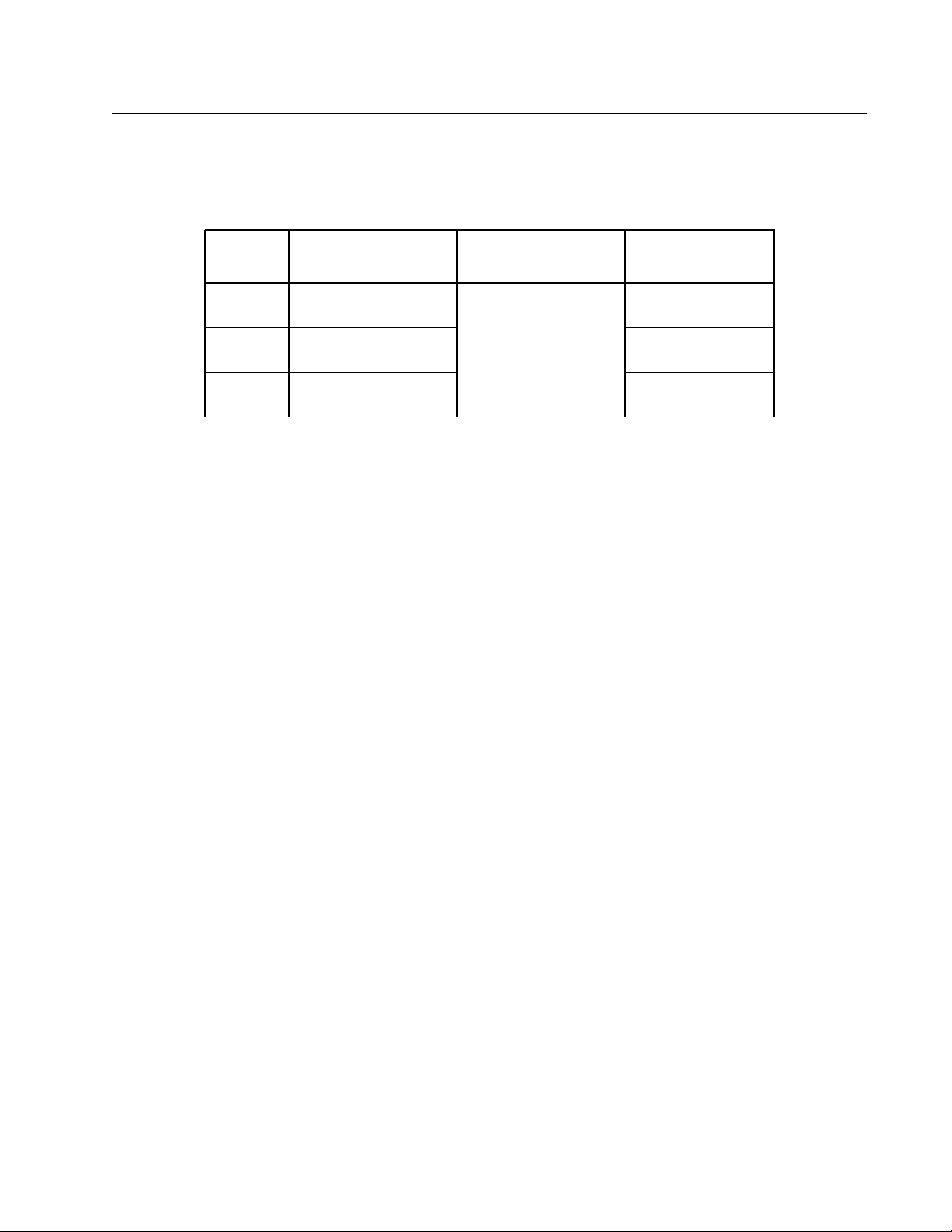
This manual covers the following models:
Cabinet Mounting
Model
AR3140 42 U
AR3340 42 U† 1 200 mm
AR3347 48 U
†
One U= 44.45 mm (1.75 in).
For a complete list of accessories and more information, see www.apc.com.
Height
†
†
External
Cabinet Width
750 mm
(29.53 in)
Cabinet
Depth
1 070 mm
(42.13 in)
(47.24 in)
1 200 mm
(47.24 in)
1 NetShelter™ SX Networking Cabinet Installation and Customization Manual
Page 6
Important Safety Information
Read the instructions carefully to become familiar with the device before trying to install, operate, service
or maintain it. The following messages may appear throughout this manual or on the equipment to warn
of potential hazards or to call attention to information that clarifies or simplifies a procedure.
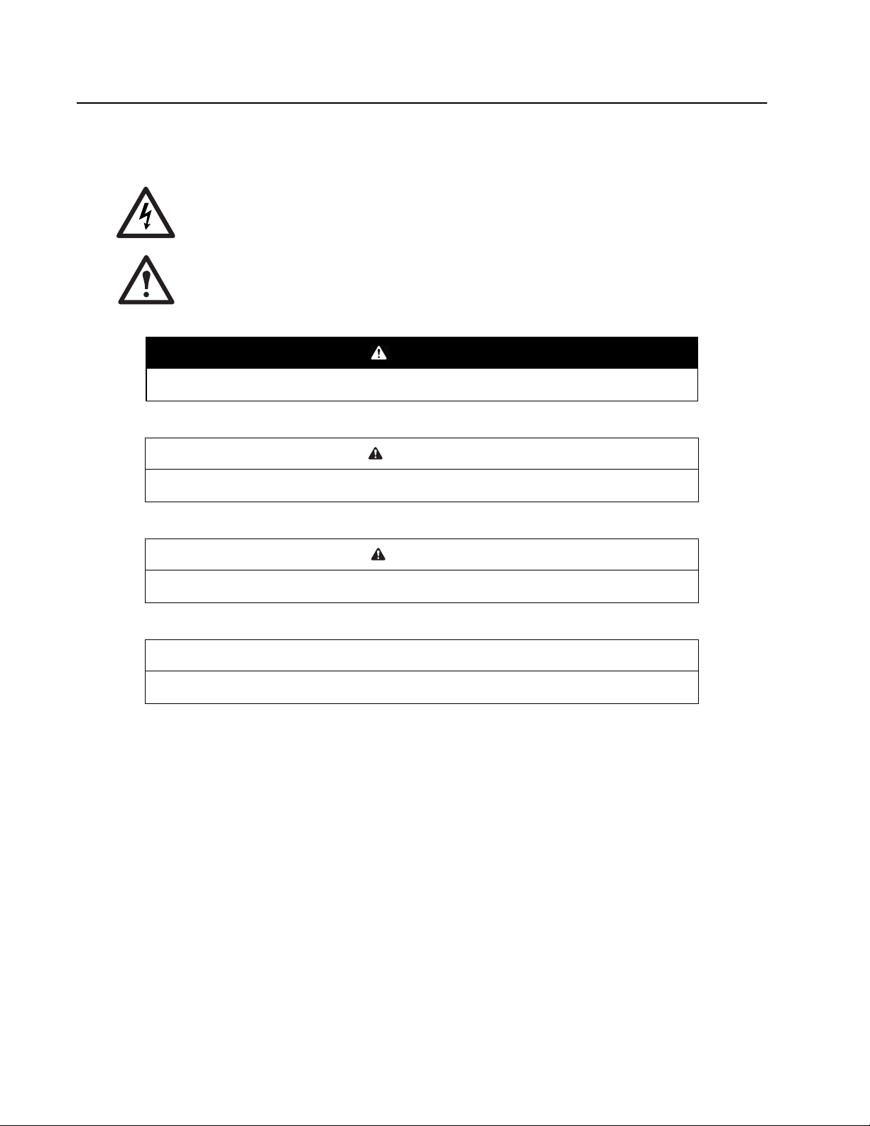
The addition of this symbol to a Danger or Warning safety label indicates that an electrical
hazard exists which will result in personal injury if the instructions are not followed.
This is the safety alert symbol. It is used to alert you to potential personal injury hazards.
Obey all safety messages that follow this symbol to avoid possible injury or death.
DANGER
DANGER indicates an imminently hazardous situation which, if not avoided, will result in death
or serious injury.
WARNING
WARNING indicates a potentially hazardous situation which, if not avoided, can result in death
or serious injury.
CAUTION
CAUTION indicates a potentially hazardous situation which, if not avoided, can result in minor
or moderate injury.
NOTICE
NOTICE addresses practices not related to physical injury including certain environmental
hazards, potential damage or loss of data.
NetShelter™ SX Networking Cabinet Installation and Customization Manual2
Page 7

Safety Instructions for the NetShelter SX Networking Cabinet
This manual contains important instructions that must be followed during the installation and
customization of the cabinet.
WARNING
TIP HAZARD
• This cabinet is easily tipped. Use extreme caution when unpacking or moving.
• When moving the cabinet on its caters, push only from the front or back.
• Before moving the cabinet on its casters, load 158 kg (350 lb) of equipment into the
bottom of the cabinet for extra stability.
• Make sure the leveling feet are up when moving the cabinet on its casters.
Failure to follow these instructions can result in death or serious injury.
WARNING
HEAVY EQUIPMENT HAZARD
At least two people are required to unpack the cabinet.
Failure to follow these instructions can result in death or serious injury.
Labels
Look for additional safety information affixed to the cabinet. See “Labels” on page 6 for more information.
3 NetShelter™ SX Networking Cabinet Installation and Customization Manual
Page 8
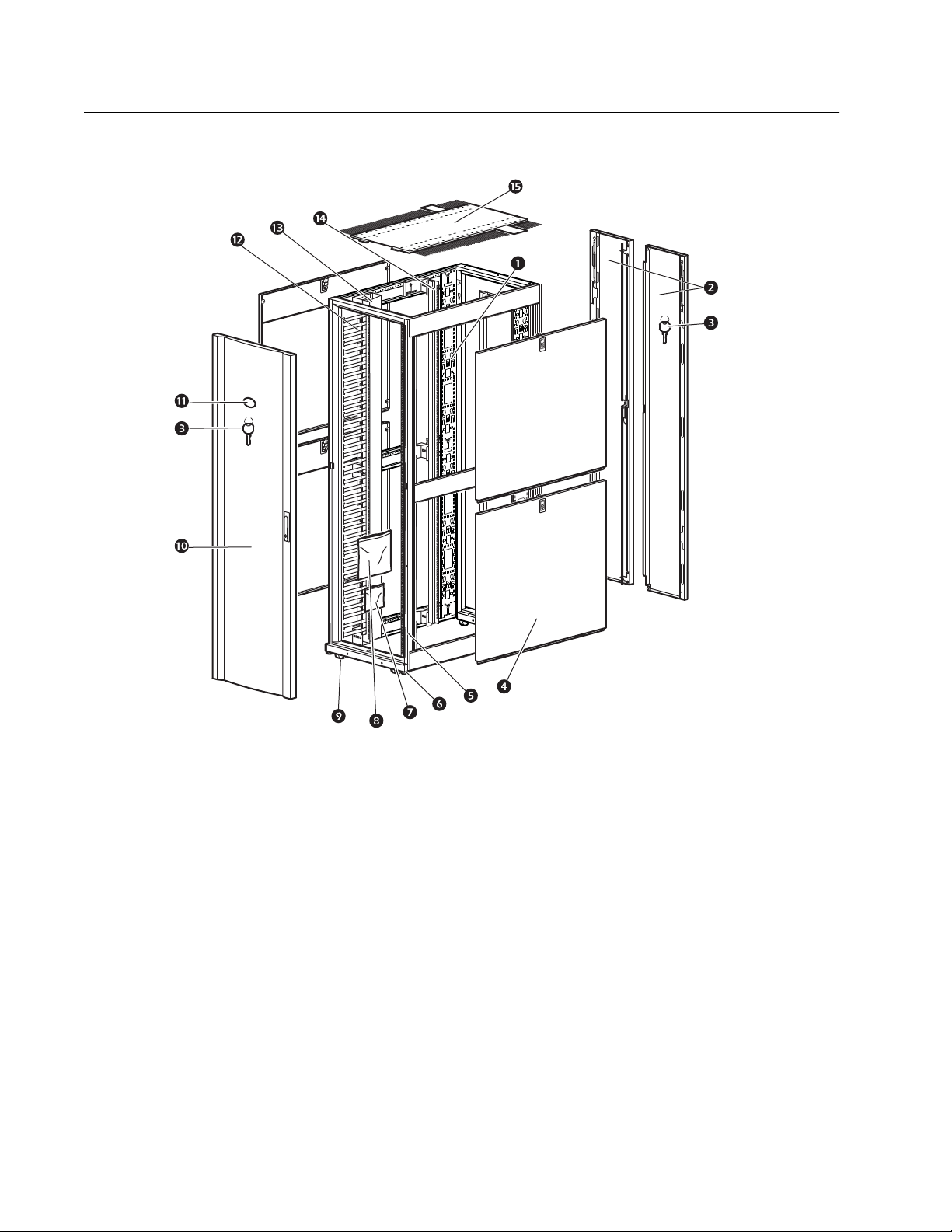
Component Identification
Adjustable Vertical 0 U Accessory Channel
Removable Rear Split Doors
Key for Doors and Side Panels
Removable Side Panels with Locks
Cabinet Frame
Adjustable Leveling Feet
Hardware Bag (see page 5)Roof
Airflow Management Kit (see page 5)
Casters
Removable and Reversible Front Door
Nameplate (if equipped)
Vertical Cable Managers
Mounting Rail Cable Manager
Vertical Mounting Rails
ns1451a
NetShelter™ SX Networking Cabinet Installation and Customization Manual4
Page 9
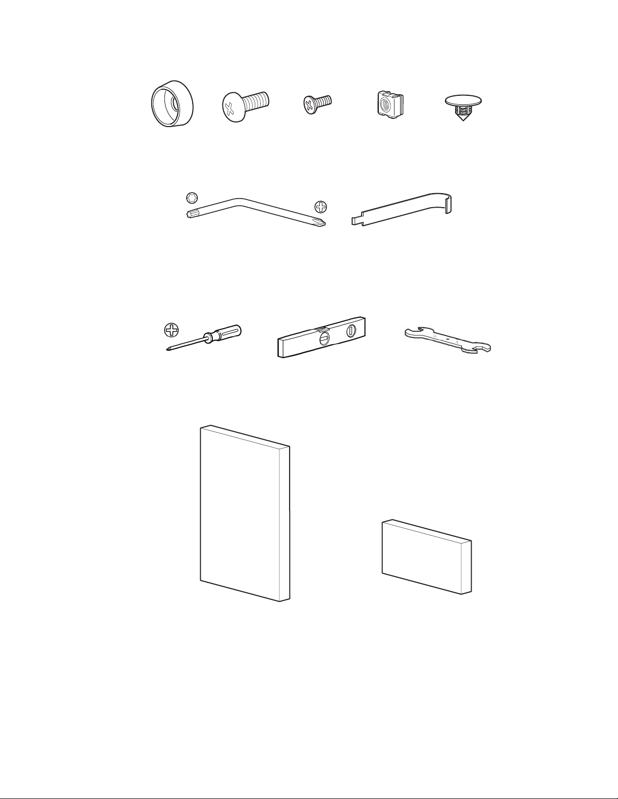
Hardware Bag
Plastic cup
washers (60)
TORX® T30/#2 Phillips wrench Cage nut tool
M6 x 16
Phillips slot
screws (60)
M5 x 12
screws (4)
Required Tools (not provided)
Phillips head screwdriver Level 13/14-mm wrench
Airflow Management Kit
Cage nuts
(60)
7-mm hole
plugs (4)
3 U Foam panel
42 U [AR3140 and AR3340] (12)
48 U [AR3347] (14)
1 U Foam Panel (4)
5 NetShelter™ SX Networking Cabinet Installation and Customization Manual
Page 10
Preparation
Move the Cabinet
TIP HAZARD
• This cabinet is easily tipped. Use extreme caution when unpacking or moving.
• At least two people are required to unpack the cabinet.
• Before moving the cabinet on its casters, load 158 kg (350 lbs) of equipment into the
bottom of the cabinet for extra stability.
• When moving on its casters, make sure the leveling feet are up, and push the cabinet
from the front or rear.
Failure to follow these instructions can result in death or serious injury.
WARNING
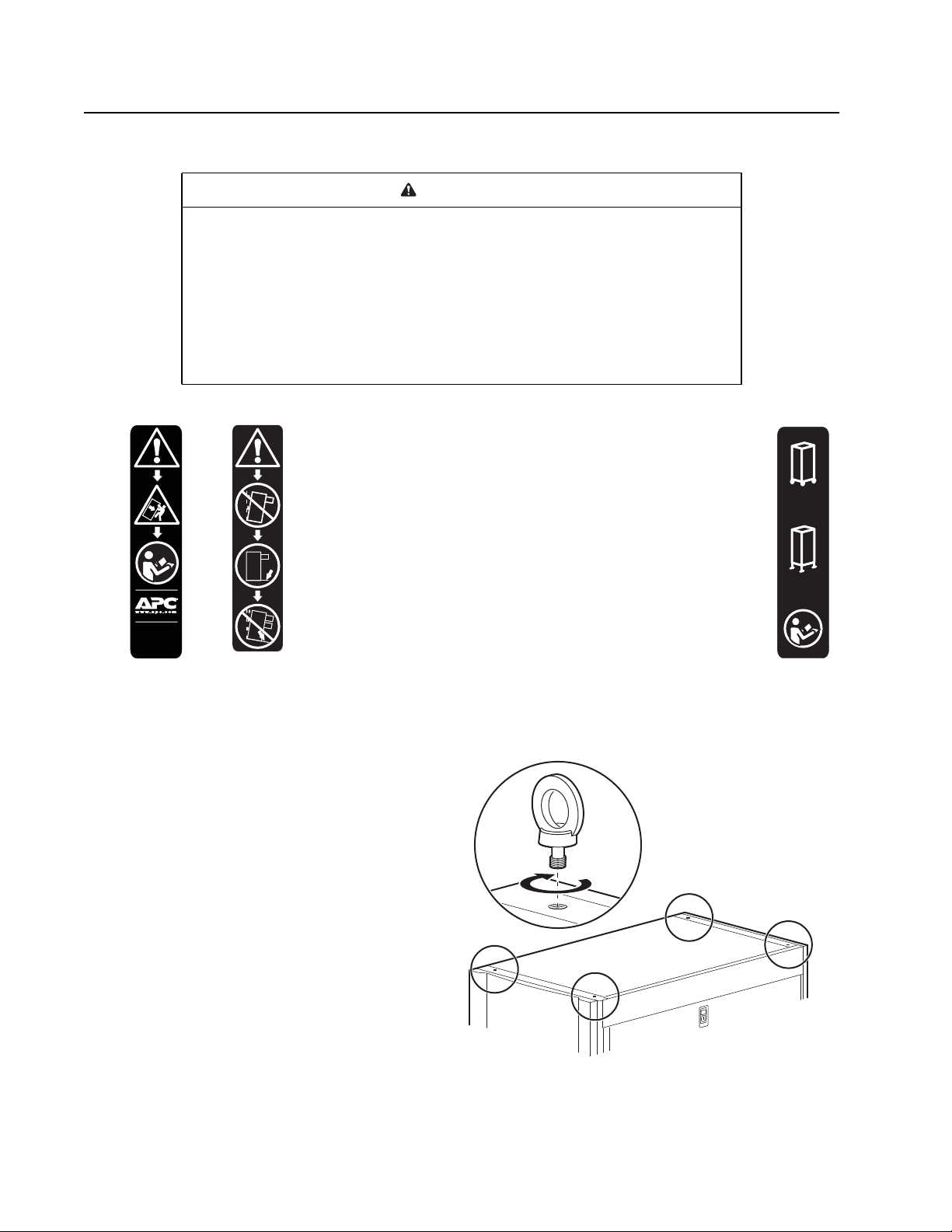
Labels: The following labels can be found on the cabinet, and
serve to communicate the following information:
Label : Generic Tip Hazard.
Label : Extend Slide-Mounted Hardware One Piece at a Time. Do
not extend loaded top-mounted sliding hardware unless the cabinet
is secured to the floor.
Casters: The cabinet can be moved on its casters with up to
1 020.58 kg (2,250 lb) of equipment installed. Once in place, lower
U.S. Patent No.
初⦌₢Ⓒ⚆
7,293,666
the leveling feet. With the leveling feet lowered, the static cabinet
can be loaded to 1 704.97 kg (3,750 lb).
NOTE: Some labels on cabinet indicate caster related information.
See label to right.
Eye bolts: The cabinet can be lifted using
eye bolts with up to 567 kg (1,250 lbs) of
equipment installed. Use M10 eye bolts with
a shoulder rated for 181 kg (400 lbs).
Casters
2250 lbs Max
(1020 kg)
Leveling Feet:
3000 lbs Max
(1361 kg)
ns0882b
NetShelter™ SX Networking Cabinet Installation and Customization Manual6
Page 11
Level the Cabinet
DANGER
HAZARD OF ELECTRIC SHOCK
When installing the doors, remember to reconnect all ground and other connection wires.
Failure to follow these instructions will result in death or serious injury.
NOTE: The leveling feet of the cabinet provide a stable base on an uneven floor. They cannot
compensate for a badly sloped surface.
1. Ensure the cabinet is in its intended location. Remove the front and rear doors.
See “Door removal” on page 13 for more information.
NOTE: Before removing the front door, disconnect the ground wires and any other wire
connections that may interfere with the removal of the doors.
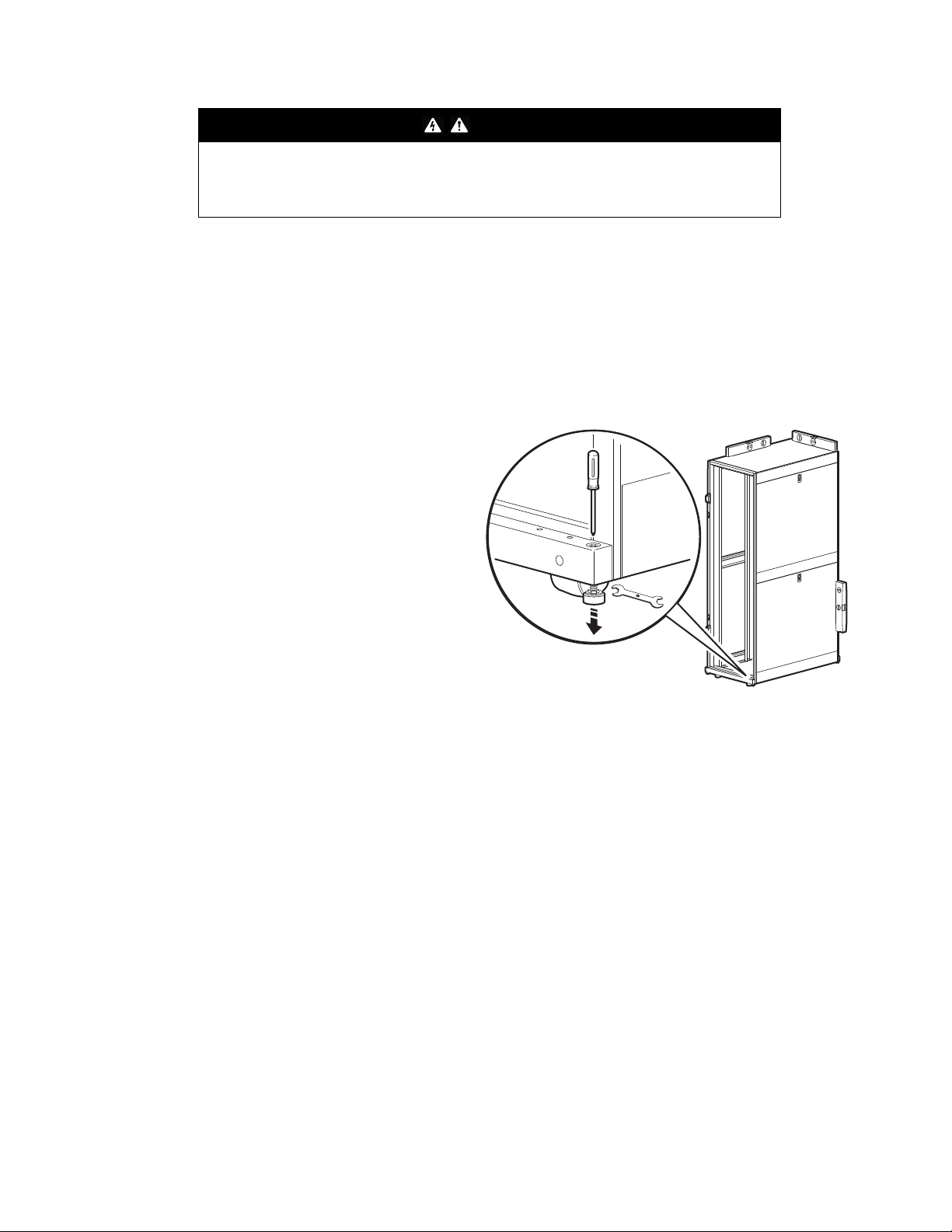
2. Insert a Phillips head screwdriver
into the screw above the leveling
foot. Turn the screw to the right to
extend the leveling foot until it makes
firm contact with the floor.
NOTES:
– This method works best with an
empty, or near empty cabinet.
– If the cabinet is loaded with
equipment, a
13 mm open ended wrench can
also be used to lower the leveling
feet.
– Door removal is not required if
using the 13 mm open-ended
wrench.
ns1632b
3. Adjust each foot and, using a level, adjust the feet until the cabinet is level and plumb.
4. If desired, join the cabinets. See “Join the Cabinets” on page 8.
5. If desired, install the front and rear doors. See “Door installation” on page 14.
7 NetShelter™ SX Networking Cabinet Installation and Customization Manual
Page 12
Join the Cabinets
WARNING
TIP HAZARD
Joining cabinets provides limited stability to the cabinets. Secure the cabinet to the floor
before installing equipment.
Failure to follow these instructions can result in death or serious injury.
DANGER
HAZARD OF ELECTRIC SHOCK
When installing the doors, remember to reconnect all ground and other connection wires.
Failure to follow these instructions will result in death or serious injury.
Join two or more cabinets together using the supplied joining hardware. Joining cabinets together may
assist in alignment and provide limited increased stability.
NOTE: Cabinets can be joined with or without side panels installed.
1. Make sure that the leveling feet are down and the cabinets are level. See “Level the Cabinet” on
page 7.
2. Remove the front and rear doors, if applicable. See “Door removal” on page 13 for more
information.
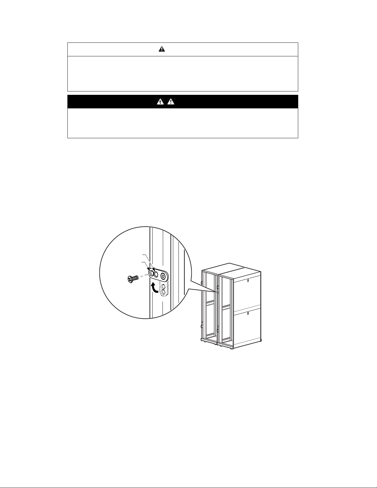
3. Locate the joining brackets. Choose between 24 in centers or 600 mm centers (see the detail
view below).
600 mm
24 in.
ns1594b
4. Align the cabinets and join them using one M5 x 12 flat-head screw (provided in the hardware
bag) per bracket. There are two brackets for the front and two brackets for the rear.
5. Reinstall the doors. See “Door installation” on page 14 for more information.
NetShelter™ SX Networking Cabinet Installation and Customization Manual8
Page 13

42/48 U Joining Trim Kit - AR7600 (Optional)
Joining trim is available for order. This item fills the gap
present between cabinets spaced on 24 in centers.
ns1755a
9 NetShelter™ SX Networking Cabinet Installation and Customization Manual
Page 14

Ground the Cabinet
DANGER
HAZARD OF ELECTRIC SHOCK
The cabinet must be connected to the building Common Bonding Network (CBN).
Failure to follow these instructions will result in death or serious injury.
Each cabinet should be bonded directly to a common ground using one of the designated grounding
locations (two M6 threaded inserts) at the bottom of the cabinet.
• Use a Common Bonding Network Jumper kit (for example, Listed [KDER] Panduit®
RGCBNJ660PY or equivalent).
• Use paint-piercing washers between ground terminal and cabinet frame or remove paint on frame
under ground terminals per NEC NFPA 70 Article 250.12.
• Torque screws to 6.9 N•m (60 lb-in).
• Do not ground cabinets in a cascading style.
ns1617b
NOTE: If needed, additional functional grounding points
are available at the top of the cabinet. Do not connect
the building CBN to these functional grounding points.
ns2306b
NetShelter™ SX Networking Cabinet Installation and Customization Manual10
Page 15

Stabilization Options
WARNING
TIP HAZARD
Secure the cabinet to the floor before installing equipment.
Failure to follow these instructions can result in death, serious injury, or equipment
damage.
The cabinet can be bolted to the floor internally or externally, as shown below. See www.apc.com for a
complete list of available stabilization options.
NOTE: Only use the stabilization accessories with the casters or leveling feet installed.
Accessory Part Number Description
Pallet/bolt-down
Provided Attaches to the rack and floor, internally
brackets
NetShelter SX
stabilizer plate
Option
(AR7700)
Bolt-down kit Option
(AR7701)
High-seismic
region
Option
(AR7701A-S)
bolt-down kit
or externally, to provide additional
stability without blocking cable access.
Designed for use in low and moderate
seismic regions.
Attaches externally to the rack and floor
to provide additional stability. Designed
for use in low and moderate seismic
regions.
ns0702a
Attaches to the rack and floor, internally
or externally, to provide additional
stability without blocking cable access.
Designed for use in low and moderate
seismic regions.
Attaches to rack and floor, internally and
externally, to provide additional stability
without blocking cable access. With the
appropriate mounting hardware, meets
high seismic region (UBC Zone-4)
requirements.
NOTE: Not a substitute for racks
designed to meet UBC Zone-4
requirements.
ns1780b
11 NetShelter™ SX Networking Cabinet Installation and Customization Manual
Page 16

Cabinet Installation
Side Panels
na2591a
Roof
X2
ns1724b
NetShelter™ SX Networking Cabinet Installation and Customization Manual12
Page 17

Doors
Door removal
This procedure can apply to the front or rear doors.
If you intend to reinstall the door in the same position, disconnect the ground wire. Otherwise, use the
TORX wrench (provided) to remove the ground wire completely. Then lift the door up off the hinges.
ns1405b
13 NetShelter™ SX Networking Cabinet Installation and Customization Manual
Page 18

Door installation
DANGER
HAZARD OF ELECTRIC SHOCK
When installing the doors, remember to reconnect all ground and other connection wires.
Failure to follow these instructions will result in death or serious injury.
This procedure can apply to the front or rear doors
NOTE: The front door can be attached on either the left or right side of the cabinet. When facing the
cabinet, this procedure installs the door on the left side, causing the door to open from the right.
1. With the door at a
90-degree angle to the front
of the cabinet, position the
door over the
hinge pins .
NOTE: Doors self-align on
hinge pins when properly
reinstalled.
2. Use slight pressure to pull
the door away from the
cabinet, then lower the door.
3. Connect the ground wire.
ns1750b
ns1751b
ns1752b
NetShelter™ SX Networking Cabinet Installation and Customization Manual14
Page 19

Front door reversal
DANGER
HAZARD OF ELECTRIC SHOCK
When installing the doors, remember to reconnect all ground and other connection wires.
Failure to follow these instructions will result in death or serious injury.
The front door can be attached on either side of the cabinet. When facing the cabinet, this procedure
installs the door on the right side, causing it to open from the left.
NOTE: If installed, the front door will need to be removed. See “Door removal” on page 13 before you
proceed.
1. Remove the handle assembly.
2. Remove the nameplate
(if equipped).
3. Remove the hinges. Rotate the
hinges 180 degrees and install
them on the opposite side of the
front door frame of the cabinet.
ns1613a
ns1824a
15 NetShelter™ SX Networking Cabinet Installation and Customization Manual
Page 20

4. Rotate the door. Reposition
and install the hinges in the
door as shown.
5. Install the door on the right
side of the cabinet and
connect the ground wire.
See “Door installation” on
page 14.
6. Install the handle on the
door with the washer rotated
90-degrees from its original
position, and the latch
rotated 180 degrees from
its original position.
ns2289a
7. Remove the nameplate
from the bottom of the door
and install as shown,
if applicable.
ns1766d
241 mm
(9.5 in.)
335 mm
(13.2 in.)
ns1253d
NetShelter™ SX Networking Cabinet Installation and Customization Manual16
Page 21

Equipment Installation
NOTE: NetShelter SX cabinets are intended for use with Listed equipment. Carefully evaluate the safety
of any configuration using un-Listed equipment.
Vertical Mounting Rails
Equipment is secured to the vertical mounting rails. The
installation of some equipment may require adjusting the
position of the vertical mounting rails.
The vertical mounting rails can be moved towards the front or
rear of the cabinet to accommodate different rails or equipment
of various depths.
Default depth of factory installed vertical mounting rails:
• 1 070 mm (42.13 in) deep cabinet: 558.8 mm (22 in)
• 1 200 mm (47.24 in) deep cabinet: 749.3 mm (29.5 in)
The minimum rail depth is 279.4 mm (11 in). The maximum rail
depth is as follows:
• 1 070 mm (42.13 in) deep cabinet: 819 mm (32.25 in)
• 1 200 mm (47.24 in) deep cabinet: 959 mm (37.75 in)
ns1453a
17 NetShelter™ SX Networking Cabinet Installation and Customization Manual
Page 22

Adjust the Vertical Mounting Rails
FALLING EQUIPMENT HAZARD
Vertical mounting rails must have all rail-mounted equipment removed before any adjustments
are attempted.
Failure to follow these instructions can result in minor or moderate injury.
1. Remove the cable manager from the
front left vertical mounting rail.
CAUTION
2. Use the Torx T30/#2 Phillips wrench
(provided) to loosen each of the three
screws, located at the top, bottom,
and middle of the rail.
ns1561a
ns0977b
NetShelter™ SX Networking Cabinet Installation and Customization Manual18
Page 23

3. Lower the three flat brackets, which
unlock the vertical mounting rail, and
slide the vertical mounting rail to the
desired location.
4. Locate the visible symbol (in the
illustration, a diamond), along the
vertical mounting rail. To align the
vertical mounting rail, make sure the
same symbol is visible through all
three corresponding holes.
NOTE: In the factory-standard
position, diamonds are visible.
ns0717c
NOTE: Vertical mounting rails adjust in 6 mm
(1/4 in) increments.
5. Ensure all vertical mounting rails have
the same visible symbol.
ns0718c
19 NetShelter™ SX Networking Cabinet Installation and Customization Manual
Page 24

6. When the vertical mounting rail is aligned
(top, middle, and bottom), raise the flat
bracket until the teeth in the bracket engage
fully with the teeth in the side brace. Then
tighten the screws, locking the rail in place.
Install Equipment in the Cabinet
WARNING
TIP HAZARD
• This cabinet is easily tipped. Follow all tipping precautions during and after equipment installation.
• Secure the cabinet to the floor before installing equipment.
• Install the heaviest equipment first toward the bottom of the cabinet to prevent the cabinet from
becoming top heavy.
• Do not extend equipment on sliding rails until minimum of 158 kg (350 lbs) of equipment is
installed into the bottom of the cabinet. Alternately, the stabilizer plate or bolt-down brackets can
also be installed. Do not extend more than one piece of equipment on sliding rails at a time.
Failure to follow these instructions can result in death or serious injury.
ns0719c
Identify one U-space on the vertical mounting rail
• Review the equipment manufacturer’s installation instructions.
• When installing equipment, locate the top and bottom of a U-space on
the mounting rails.
• Every third hole on the mounting rails is numbered to indicate the
middle of a U-space.
• A U-space consists of a numbered hole, and the hole immediately
above and below it, as shown.
NetShelter™ SX Networking Cabinet Installation and Customization Manual20
1U
7
6
5
ns0014a
Page 25

Cage nuts
APC by Schneider Electric offers a cage nut hardware kit (AR8100) for use with square holes.
CAUTION
FALLING EQUIPMENT HAZARD
Do NOT install cage nuts vertically with the ears engaging the top and bottom of the square hole.
Failure to follow these instructions can result in minor or moderate injury.
• Install cage nuts horizontally, with the ears engaging
the sides of the square hole.
• Install the cage nuts on the interior of the vertical
mounting rail.
Installation:
1. From inside of the cabinet, insert the cage nut into the
square hole.
2. Hook one ear of the cage nut assembly through the far
side of the hole.
3. Place the cage nut tool on the other side of the cage nut
and pull to snap into position.
ns1768a
Removal:
1. Remove any attached screw.
2. Grasp the cage nut and squeeze the sides to release it from the square hole.
gen0188a
21 NetShelter™ SX Networking Cabinet Installation and Customization Manual
Page 26

Equipment installation accessories (not provided)
Accessory Part Number Description
Recessed rail kit
NetShelter SX
42 U, 23 in, EIA
Mounting Rails
AR7508
(for a 42 U
enclosure)
Use the recessed rail kit
to install equipment that
has a different mounting
depth from the other
AR7578
(for a 48 U
equipment in the
enclosure.
enclosure)
AR7510 For NetShelter SX
Networking 42 U,
750 mm (29.53 in) wide
enclosures (AR3140 and
AR3340) only, the
mounting rails
accommodate 23 in rack
mountable equipment.
15 U
6 U
42 U
48 U
ns1845a
Fixed shelf 50 lb AR8105BLK Cantilever fixed shelf to
enable the mounting of a
monitor or other
equipment into the rack
environment or to allow
cable pass-through from
the front to rear of the
enclosure.
NetShelter™ SX Networking Cabinet Installation and Customization Manual22
ns1494a
Page 27

Completing the Installation
Airflow Management
NOTICE
EQUIPMENT DAMAGE HAZARD
Improper airflow can damage installed components. Verify that the system provides the
specified airflow for installed components.
Failure to follow these instructions can result in equipment damage.
Foam airflow management panels assist in maintaining the required airflow. The panels install toollessly
and direct airflow by covering empty vertical cabinet space.
Foam Airflow Management Panel Installation
Install airflow management panels in the channel along the right vertical mounting rail next to inactive
equipment such as patch panels, as seen below. 1 U and 3 U panels help isolate hot air and
prevent it from entering the cold aisle. The left side of the cabinet does not require panels.
NOTES:
• The networking switch air intake areas
and the side airflow duct kit inlets must
remain unobstructed to ensure proper
airflow into the networking switches .
• Install the airflow management panels
before installing any cabling.
ns1562a
ns1497a
23 NetShelter™ SX Networking Cabinet Installation and Customization Manual
Page 28

Airflow management accessories (not provided)
Accessory Part Number Description
NetShelter SX
Side Airflow
Solution Kit
Side Airflow
Duct Kit
Required for
Cisco Nexus
7018 Switch
(AR7742 &
AR7747)
Installs onto the NetShelter SX
1200-mm Networking Cabinet
(AR3340 or AR3347) and
increases the width of the
cabinet by 127 mm (5 in) on
each side, providing the
side-to-side airflow required by
the switch. Internal baffles
isolate hot and cold air in the
cabinet.
AR7715 The NetShelter Side Airflow
Duct Kit is intended for use
with Cisco® Catalyst 6509,
6509-E, and 6513 Switches
and Cisco MDS 9509 and 9513
Multilayer Switches.
For networking switch
applications, the Side Airflow
Duct Kit allows for improved
cable management solutions
while maintaining adequate
airflow and separation of hot
and cold aisles to cool
switches. The Side Airflow
Duct Kit maintains separation
of hot and cold aisles via ducts
and baffle panels.
ns1891b
ns1548c
Airflow
Management
Blanking Panel
1 U horizontal
cable organizer
with brush strip
AR8136BLK
(Qty. 10)
Covers an empty vertical
enclosure space to maintain
proper airflow.
AR8136BLK200
(Qty. 200)
AR8429 19 in, 1 U cable pass-through
assists with containing air in
the cabinet and providing an
aesthetic solution for cable
routing.
NetShelter™ SX Networking Cabinet Installation and Customization Manual24
ns1127c
ns0404a
Page 29

Accessory Part Number Description
KoldLok® raised
floor grommet
AR7720
(Qty. 10)
AR7730
(Qty. 10)
AR7740
(Qty. 10)
Designed to seal openings in
new raised floor cutouts prior
to the installation of
communications or power
cabling.
ns1202a
ns1222a
ns1224b
25 NetShelter™ SX Networking Cabinet Installation and Customization Manual
Page 30

Cable Routing and Cable Management
The NetShelter SX Networking Cabinet has cable access openings on its roof, sides, and bottom.
Four vertical cable managers and two Vertical 0 U accessory channels are included with the cabinet and
offer a variety of other cable management accessories.
Vertical 0 U Accessory Channels
The vertical 0 U accessory channels provide toolless mounting capabilities for Rack Power Distribution
Units (PDUs), cable containment brackets, and cable tie-off locations.
The factory-default position for the vertical 0 U accessory channels is in the rear of the cabinet.
You can position the vertical accessory channels anywhere along the side braces or remove them
completely. Adjustment is similar to adjusting the vertical mounting rails (see “Adjust the Vertical
Mounting Rails” on page 18).
Additional vertical 0 U accessory channels are available for order.
Vertical Cable Managers
Remove vertical cable managers for cable routing purposes.
Re-install vertical cable managers on the vertical 0 U accessory channels.
X2
ns1511c
NetShelter™ SX Networking Cabinet Installation and Customization Manual26
Page 31

Cable management accessories (not provided)
Accessory Part Number Description
1 U data
distribution panel
2 U data
distribution panel
CAT 6 Patch
Panel
0 U data
distribution panel
AR8451
(shown)
AR8452
CAT6PNL-24
(shown)
Holds four data distribution
cables, for a total of 24 ports.
Holds eight data distribution
cables, for a total of 48 ports.
24-port RJ45 to 110 568 A/B
color-coded patch panel.
48-port RJ45 to 110 568 A/B
CAT6PNL-48
color-coded patch panel.
AR8457 Installs in a vertical 0 U
accessory channel. Holds
four data distribution cables,
for a total of 24 ports.
1
2
3
4
5
6
7
8
9
10
11
12
13
1
4
15
1
6
17
18
19
20
21
2
2
23
2
4
ns1827a
1
2
3
4
5
6
7
8
9
10
1
1
12
13
14
15
16
17
18
19
20
21
22
23
24
ns1827b
21 3 4 5 6 87 9 10 11 12 1413 15 16 17 18 2019 21 22 23 24
ns1832a
Page 32

Accessory Part Number Description
19 in horizontal
cable organizers
Cable
containment
brackets (Qty. 6)
AR8602A:
1 U, 4 in
Routes cables horizontally on
the front or back of the 19 in
EIA cabinet.
AR8612: 1 U,
6 in (shown)
AR8600A:
2 U, 4 in
AR8603A:
2 U, 6 in
AR8606: 2 U,
6 in (shown)
AR8605: 3 U,
6 in (shown)
AR7710 Contains cables along the
vertical 0 U accessory
channel. Installs without tools.
Side panel with
access holes
0 U accessory
mounting bracket
(Qty. 2)
AR7305A
(Qty. 2)
For a NetShelter SX
Networking 42U, 1 070 mm
(42.13 in) deep enclosure
(AR3140) only. Allows cable
pass-through to adjacent
enclosures. Openings contain
brushes to restrict airflow.
AR7711 0 U, multi-purpose accessory
mounting bracket for 1 U and
2 U equipment, including
Rack PDUs.
ns1889a
NetShelter™ SX Networking Cabinet Installation and Customization Manual28
Page 33

Accessory Part Number Description
Vertical cable
manager
Vertical cable
organizer for
NetShelter 0 U
accessory
channel
AR7717A For NetShelter SX
Networking 42U enclosures
(AR3140 and AR3340) only.
Installs in the vertical
mounting flanges and in the
vertical 0 U accessory
channels. The vertical cable
manager has smooth plastic
cable guides at 1 U
increments to allow patch
cords to enter and exit in an
organized manner.
AR8442
(Qty. 2)
Eliminates cable stress by
organizing cable layout within
the rear channels of the
enclosure. Uses 0 U space
within the enclosure. Consists
of two pieces of equal size.
When stacked, both pieces
span the entire height of the
enclosure. Two pieces can be
installed side by side in the
vertical 0 U accessory
channel. Can be used in any
APC enclosure.
ns1107b
NetShelter SX
42 U vertical
cable organizer
NetShelter SX
48 U vertical
cable organizer
Toolless hook
and loop cable
managers
(Qty. 10)
AR7502
(Qty. 2)
Installs in the enclosure along
the side braces. Provides
toolless mounting capabilities
for APC Rack Power
AR7572
(Qty. 2)
Distribution Units (PDU) and
APC cable containment
brackets. Provides tie-off
locations for cables.
AR8621 Includes ten 457 mm (18 in)
hook and loop black cable
straps that install in the
square holes in the vertical
0 U accessory channel or the
vertical mounting rail.
ns1852a
ns2213a
29 NetShelter™ SX Networking Cabinet Installation and Customization Manual
Page 34

Accessory Part Number Description
NetShelter SX
42 U narrow
vertical 0 U cable
organizer
Vertical fiber
organizer
AR7511
(Qty. 2)
For NetShelter SX
Networking 42U enclosures
(AR3140 and AR3340) only.
The narrow vertical 0 U
accessory channel
complements the standard
vertical 0 U accessory
channel by offering additional
cable management options.
The narrow channel can be
used in the front of the
enclosure to mount fiber
cable spools and vertical
cable managers or in the
middle of the enclosure for
cable tie off. In addition,
keyholes are provided to
mount one vertical Rack PDU
per organizer.
AR8443A The vertical fiber organizer
provides a method to manage
fiber cabling within a cabinet
and mounts toollessly into the
vertical 0 U accessory
channel.
ns1754b
Fiber organizer
spools
AR8444
(Qty. 4)
ns1163b
ns1156a
Can be mounted toollessly to
the vertical fiber organizer or
a vertical 0 U accessory
channel.
ns1163b
NetShelter™ SX Networking Cabinet Installation and Customization Manual30
Page 35

Specifications
AR3140 AR3340 AR3347
Height 1 991 mm
(78.40 in)
Width 750 mm (29.53 in) 750 mm (29.53 in) 750 mm (29.53 in)
Depth 1 070 mm
(42.13 in)
Net weight 155.95 kg
(343.10 lb)
Total open area (front
door)
Total open area (rear
door)
Open area per U
(front door)
Open area per U
(rear door)
Perforation pattern
percentage
Percent of perforated
area (front)
788 972 mm2
(1,222.91 in2)
866 920 mm2
(1,343.73 in2)
18 787 mm
(29.12 in2)
20 645 mm2
(32 in2)
69% 69% 69%
88% 88% 88%
2
1 991 mm
(78.40 in)
1 200 mm
(47.24 in)
161.36 kg
(355.00 lb)
788 972 mm2
(1,222.91 in2)
866 920 mm2
(1,343.73 in2)
18 787 mm
(29.12 in2)
20 645 mm2
(32 in2)
2
2 258 mm
(88.90 in)
1 200 mm
(47.24 in)
185.45 kg
(408.00 lb)
900 417 mm2
(1,395.65 in2)
989 243 mm2
(1,533.33 in2)
18 787 mm
(29.12 in2)
20 645 mm2
(32 in2)
2
Percent of perforated
area (rear)
Clearance (for wiring
between front door and
vertical mounting rail)
Weight rating: static
†
load
Weight rating: rolling 1 020.58 kg (2,250 lb) 1 020.58 kg (2,250 lb) 1 020.58 kg (2,250 lb)
†
Lower the leveling feet if the static weight is over 1 020.58 kg (2,250 lb).
96% 96% 96%
238.76 mm
(9.40 in)
1 704.97 kg (3,750 lb) 1 704.97 kg (3,750 lb) 1 704.97 kg (3,750 lb)
216.9 mm
(8.5 in)
216.9 mm
(8.5 in)
31 NetShelter™ SX Networking Cabinet Installation and Customization Manual
Page 36

Five-Year Factory Warranty
The limited warranty provided by APC by Schneider Electric in this Statement of Limited Factory
Warranty applies only to products you purchase for your commercial or industrial use in the ordinary
course of your business.
Terms of warranty
APC by Schneider Electric warrants its products to be free from defects in materials and workmanship
for a period of five years from the date of purchase. The obligation of APC by Schneider Electric under
this warranty is limited to repairing or replacing, at its sole discretion, any such defective products. This
warranty does not apply to equipment that has been damaged by accident, negligence, or misapplication
or has been altered or modified in any way. Repair or replacement of a defective product or part thereof
does not extend the original warranty period. Any parts furnished under this warranty may be new or
factory- remanufactured.
Non-transferable warranty
This warranty extends only to the original purchaser who must have properly registered the product. The
product may be registered at the APC by Schneider Electric Web site, www.apc.com.
Exclusions
APC by Schneider Electric shall not be liable under the warranty if its testing and examination disclose
that the alleged defect in the product does not exist or was caused by end user’s or any third person’s
misuse, negligence, improper installation or testing. Further, APC by Schneider Electric shall not be
liable under the warranty for unauthorized attempts to repair or modify wrong or inadequate electrical
voltage or connection, inappropriate on-site operation conditions, corrosive atmosphere, repair,
installation, start-up by non-APC by Schneider Electric designated personnel, a change in location or
operating use, exposure to the elements, Acts of God, fire, theft, or installation contrary to APC by
Schneider Electric recommendations or specifications or in any event if the APC by Schneider Electric
serial number has been altered, defaced, or removed, or any other cause beyond the range of the
intended use.
THERE ARE NO WARRANTIES, EXPRESS OR IMPLIED, BY OPERATION OF LAW OR
OTHERWISE, OF PRODUCTS SOLD, SERVICED OR FURNISHED UNDER THIS AGREEMENT OR
IN CONNECTION HEREWITH. APC BY SCHNEIDER ELECTRIC DISCLAIMS ALL IMPLIED
WARRANTIES OF MERCHANTABILITY, SATISFACTION AND FITNESS FOR A PARTICULAR
PURPOSE. APC BY SCHNEIDER ELECTRIC EXPRESS WARRANTIES WILL NOT BE ENLARGED,
DIMINISHED, OR AFFECTED BY AND NO OBLIGATION OR LIABILITY WILL ARISE OUT OF, APC
BY SCHNEIDER ELECTRIC RENDERING OF TECHNICAL OR OTHER ADVICE OR SERVICE IN
CONNECTION WITH THE PRODUCTS. THE FOREGOING WARRANTIES AND REMEDIES ARE
EXCLUSIVE AND IN LIEU OF ALL OTHER WARRANTIES AND REMEDIES. THE WARRANTIES
SET FORTH ABOVE CONSTITUTE APC BY SCHNEIDER ELECTRIC’S SOLE LIABILITY AND
PURCHASER'S EXCLUSIVE REMEDY FOR ANY BREACH OF SUCH WARRANTIES. APC BY
SCHNEIDER ELECTRIC WARRANTIES EXTEND ONLY TO PURCHASER AND ARE NOT
EXTENDED TO ANY THIRD PARTIES.
IN NO EVENT SHALL APC BY SCHNEIDER ELECTRIC, ITS OFFICERS, DIRECTORS, AFFILIATES
OR EMPLOYEES BE LIABLE FOR ANY FORM OF INDIRECT, SPECIAL, CONSEQUENTIAL OR
PUNITIVE DAMAGES, ARISING OUT OF THE USE, SERVICE OR INSTALLATION, OF THE
PRODUCTS, WHETHER SUCH DAMAGES ARISE IN CONTRACT OR TORT, IRRESPECTIVE OF
FAULT, NEGLIGENCE OR STRICT LIABILITY OR WHETHER APC BY SCHNEIDER ELECTRIC HAS
BEEN ADVISED IN ADVANCE OF THE POSSIBLY OF SUCH DAMAGES. SPECIFICALLY, APC BY
SCHNEIDER ELECTRIC IS NOT LIABLE FOR ANY COSTS, SUCH AS LOST PROFITS OR
REVENUE, LOSS OF EQUIPMENT, LOSS OF USE OF EQUIPMENT, LOSS OF SOFTWARE, LOSS
OF DATA, COSTS OF SUBSTITUENTS, CLAIMS BY THIRD PARTIES, OR OTHERWISE.
NetShelter™ SX Networking Cabinet Installation and Customization Manual32
Page 37

NO SALESMAN, EMPLOYEE OR AGENT OF APC BY SCHNEIDER ELECTRIC IS AUTHORIZED TO
ADD TO OR VARY THE TERMS OF THIS WARRANTY. WARRANTY TERMS MAY BE MODIFIED, IF
AT ALL, ONLY IN WRITING SIGNED BY AN APC BY SCHNEIDER ELECTRIC OFFICER AND
LEGAL DEPARTMENT.
Warranty claims
Customers with warranty claims issues may access the APC by Schneider Electric customer support
network through the Support page of the APC by Schneider Electric Web site, www.apc.com/support.
Select your country from the country selection pull-down menu at the top of the Web page. Select the
Support tab to obtain contact information for customer support in your region.
33 NetShelter™ SX Networking Cabinet Installation and Customization Manual
Page 38

Page 39

Page 40

Worldwide Customer Support
Customer support for this product is available at www.apc.com.
© 2020 APC by Schneider Electric. APC, the APC logo, and NetShelter are owned by Schneider Electric SE or
its subsidiaries. All other brands may be trademark of their respective owners.
990-3548D-001
12/2019
 Loading...