

Arbor Technology ASLAN-W910C, ASLAN-W922C-IP, ASLAN-W900, ASLAN-W912C, ASLAN-W915C User Manual
...
I
ASLAN-W9XXC/917X
Fanless Industrial Panel PC with Intel® Core
i5-6300U 2.4GHz Processor
User’s Manual
Version 1.0
2017.09
P/N: 4019090000100P

- II -
Revision History
Version Date Description
1.0 2017.09 Initial release

- i -
Contents
Revision History ................................................................................II
Contents .............................................................................................. i
Preface...............................................................................................iii
Copyright Notice .....................................................................................iii
Declaration of Conformity .......................................................................iii
CE ....................................................................................................iii
FCC Class A ....................................................................................iii
RoHS .............................................................................................. iv
SVHC / REACH .............................................................................. iv
Important Safety Instructions .................................................................. v
Warning .................................................................................................. vi
Lithium Battery Replacement ................................................................. vi
Technical Support .................................................................................. vi
Warranty.................................................................................................vii
Chapter 1 - Introduction .................................................................... 1
1.1. The Computer .................................................................................. 2
1.2. About this Manual ........................................................................... 2
1.3. Specications ................................................................................... 3
1.4. Inside the Package ..........................................................................5
1.5. Ordering Information ........................................................................ 5
Chapter 2 - Getting Started ............................................................... 7
2.1. Dimensions ......................................................................................8
2.2. Tour the Computer ......................................................................... 11
2.2.1. Front View ............................................................................ 11
2.2.2. Top/Bottom View .................................................................. 11
2.3. Driver Installation Note ...................................................................13
Chapter 3 - Engine of the Computer .............................................. 15
3.1. Board Layout ..................................................................................16
3.2. Jumpers and Connectors ............................................................... 19
3.2.1 Main Board (FMB-i89U1) ...................................................... 19
3.2.1.1. Jumpers ........................................................................... 19
3.2.1.1. Connectors ......................................................................24
3.2.2 Daughter Board (SCB-1299H) ..............................................48
Chapter 4 - Installation and Maintenance ......................................57
4.1. Disassembly the Computer ............................................................ 58
4.1.1 ASLAN-W910C/912C ...........................................................58
4.1.2. ASLAN-917X/W915C/919C/922C .......................................60
4.2. Install Hardware ............................................................................. 61
4.2.1. Install Wi-Fi Module .............................................................61
Contents

- ii -
Contents
4.2.1. Install mSATA Module .......................................................... 67
4.2.1. Install SSD or HDD .............................................................. 69
4.3. Mount the Computer ......................................................................71
4.3.1. Panel Mounting .................................................................... 71
4.3.2. VESA Mounting .................................................................... 74
Chapter 5 - BIOS .............................................................................. 75
5.1. Main ...............................................................................................78
5.2. Advanced .......................................................................................79
5.2.1. CPU Conguration ............................................................... 80
5.2.2. PCI Sybsystem Settings ......................................................81
5.2.3. ACPI Settings .......................................................................82
5.2.4. AMT Conguration ............................................................... 83
5.2.5. F71869A Super IO Conguration ......................................... 84
5.2.6. Hardware Monitor ................................................................85
5.2.7. F81216SEC Super IO Conguration ...................................86
5.2.8. S5 RTC Wake Settings ........................................................ 87
5.2.9. SATA Conguration ..............................................................88
5.2.10. CSM Conguration ............................................................89
5.2.11. USB Conguration ............................................................. 90
5.3. Chipset ........................................................................................... 92
5.3.1. System Agent (SA) Conguration ........................................ 93
5.3.2. PCH-IO Conguration .......................................................... 96
5.4 Security ........................................................................................... 99
5.5. Boot ..............................................................................................100
5.6. Save & Exit ..................................................................................101

- iii -
Preface
Copyright Notice
All Rights Reserved.
The information in this document is subject to change without prior notice in
order to improve the reliability, design and function. It does not represent a
commitment on the part of the manufacturer.
Under no circumstances will the manufacturer be liable for any direct, indirect,
special, incidental, or consequential damages arising from the use or inability
to use the product or documentation, even if advised of the possibility of such
damages.
This document contains proprietary information protected by copyright. All rights
are reserved. No part of this document may be reproduced by any mechanical,
electronic, or other means in any form without prior written permission of the
manufacturer.
Declaration of Conformity
CE
The CE symbol on your product indicates that it is in compliance with the
directives of the Union European (EU). A Certicate of Compliance is available
by contacting Technical Support.
This product has passed the CE test for environmental specications when
shielded cables are used for external wiring. We recommend the use of shielded
cables. This kind of cable is available from ARBOR. Please contact your local
supplier for ordering information.
Warning
This is a class A product. In a domestic environment this product may cause
radio interference in which case the user may be required to take adequate
measures.
FCC Class A
This device complies with Part 15 of the FCC Rules. Operation is subject to the
following two conditions:
(1) This device may not cause harmful interference, and
(2) This device must accept any interference received, including interference
that may cause undesired operation.

- iv -
Preface
NOTE:
This equipment has been tested and found to comply with the limits for a
Class A digital device, pursuant to Part 15 of the FCC Rules. These limits are
designed to provide reasonable protection against harmful interference when the
equipment is operated in a commercial environment. This equipment generates,
uses, and can radiate radio frequency energy and, if not installed and used in
accordance with the instruction manual, may cause harmful interference to radio
communications. Operation of this equipment in a residential area is likely to
cause harmful interference in which case the user will be required to correct the
interference at his own expense.
RoHS
ARBOR Technology Corp. certies that all components in its products are
in compliance and conform to the European Union’s Restriction of Use of
Hazardous Substances in Electrical and Electronic Equipment (RoHS) Directive
2002/95/EC.
The above mentioned directive was published on 2/13/2003. The main purpose
of the directive is to prohibit the use of lead, mercury, cadmium, hexavalent
chromium, polybrominated biphenyls (PBB), and polybrominated diphenyl
ethers (PBDE) in electrical and electronic products. Member states of the EU are
to enforce by 7/1/2006.
ARBOR Technology Corp. hereby states that the listed products do not contain
unintentional additions of lead, mercury, hex chrome, PBB or PBDB that exceed
a maximum concentration value of 0.1% by weight or for cadmium exceed
0.01% by weight, per homogenous material. Homogenous material is dened as
a substance or mixture of substances with uniform composition (such as solders,
resins, plating, etc.). Lead-free solder is used for all terminations (Sn(96-96.5%),
Ag(3.0-3.5%) and Cu(0.5%)).
SVHC / REACH
To minimize the environmental impact and take more responsibility to the earth
we live, Arbor hereby conrms all products comply with the restriction of SVHC
(Substances of Very High Concern) in (EC) 1907/2006 (REACH --Registration,
Evaluation, Authorization, and Restriction of Chemicals) regulated by the
European Union.
All substances listed in SVHC < 0.1 % by weight (1000 ppm)

- v -
Preface
Important Safety Instructions
Read these safety instructions carefully
1. Read all cautions and warnings on the equipment.
2. Place this equipment on a reliable surface when installing. Dropping it or
letting it fall may cause damage
3. Make sure the correct voltage is connected to the equipment.
4. For pluggable equipment, the socket outlet should be near the equipment
and should be easily accessible.
5. Keep this equipment away from humidity.
6. The openings on the enclosure are for air convection and protect the
equipment from overheating. DO NOT COVER THE OPENINGS.
7. Position the power cord so that people cannot step on it. Do not place
anything over the power cord.
8. Never pour any liquid into opening. This may cause re or electrical shock.
9. Never open the equipment. For safety reasons, the equipment should be
opened only by qualied service personnel.
10. If one of the following situations arises, get the equipment checked by
service personnel:
a. The power cord or plug is damaged.
b. Liquid has penetrated into the equipment.
c. The equipment has been exposed to moisture.
d. The equipment does not work well, or you cannot get it to work according
to the user’s manual.
e. The equipment has been dropped or damaged.
f. The equipment has obvious signs of breakage.
11. Keep this User’s Manual for later reference.

- vi -
Preface
Warning
The Box PC and its components contain very delicately Integrated Circuits (IC).
To protect the Box PC and its components against damage caused by static
electricity, you should always follow the precautions below when handling it:
1. Disconnect your Box PC from the power source when you want to work on
the inside.
2. Use a grounded wrist strap when handling computer components.
3. Place components on a grounded antistatic pad or on the bag that came
with the Box PC, whenever components are separated from the system.
Lithium Battery Replacement
Incorrect replacement of the lithium battery may lead to a risk of explosion.
The lithium battery must be replaced with an identical battery or a battery type
recommended by the manufacturer.
Do not throw lithium batteries into the trash can. It must be disposed of in
accordance with local regulations concerning special waste.
Technical Support
If you have any technical difculties, please consult the user’s manual rst at:
http://www.arbor.com.tw
Please do not hesitate to call or e-mail our customer service when you still cannot
nd out the answer.
http://www.arbor-technology.com
E-mail:info@arbor.com.tw

- vii -
Preface
Warranty
This product is warranted to be in good working order for a period of one year
from the date of purchase. Should this product fail to be in good working order
at any time during this period, we will, at our option, replace or repair it at no
additional charge except as set forth in the following terms. This warranty does
not apply to products damaged by misuse, modications, accident or disaster.
Vendor assumes no liability for any damages, lost prots, lost savings or any
other incidental or consequential damage resulting from the use, misuse of, or
inability to use this product. Vendor will not be liable for any claim made by any
other related party.
Vendors disclaim all other warranties, either expressed or implied, including but
not limited to implied warranties of merchantability and tness for a particular
purpose, with respect to the hardware, the accompanying product’s manual(s)
and written materials, and any accompanying hardware. This limited warranty
gives you specic legal rights.
Return authorization must be obtained from the vendor before returned
merchandise will be accepted. Authorization can be obtained by calling or faxing
the vendor and requesting a Return Merchandise Authorization (RMA) number.
Returned goods should always be accompanied by a clear problem description.

- viii -
This page is intentionally left blank.

- 1 -
1Chapter 1
Introduction
Chapter 1 - Introduction

- 2 -
Introduction
1.1. The Computer
Product Highlights
• 10~21.5" LCD Display w/ LED Backlight
• Flat panel with resistive touchscreen
/ projected capacitive touchscreen
(depending on model)
• Front panel compliant with IP65
• Anti-scratch surface: 7H hardness (ASLAN-
W9XXC)
• Mini PCIe expansion slot support
• Fanless cooling system
• Cable-less Design
• Low power consumption
• 2 x SMA antenna holes for optional WiFi function
1.2. About this Manual
This manual is meant for the experienced users and integrators with hardware
knowledge of personal computers. If you are not sure about the description in
this manual, consult your vendor before further handling.
We recommend that you keep one copy of this manual for the quick reference
for any necessary maintenance in the future. Thank you for choosing ARBOR
products.

- 3 -
Introduction
1.3. Specications
System
CPU Intel® Core i5-6300U™ Processor 2.4GHz
Memory 1 x 4GB DDR4 SO-DIMM RAM module installed
LAN Chipset
1 x Intel
®
i219LM PCIe controller w/ iAMT
1 x Intel
®
i210IT PCIe controller
Watchdog Timer 1~255 levels reset
Storage
Device
2 x 2.5” drive bay (default) (only for ASLAN-917X/W915C/W919C/W922C)
1 x mSATA
Audio
Device Line Out / Mic In (Optional)
LCD Display
Size/Type
ASLAN-917X 17" TFT LCD Panel
ASLAN-W910C 10.1" TFT LCD Panel
ASLAN-W912C 11.6" TFT LCD Panel
ASLAN-W915C 15.6" TFT LCD Panel
ASLAN-W919C 18.5" TFT LCD Panel
ASLAN-W922C 21.5" TFT LCD Panel
Max. Resolution
ASLAN-917X 1280x1024, SXGA
ASLAN-W910C 1280 x 800, WXGA
ASLAN-W912C/W922C 1920 x 1080, Full HD
ASLAN-W915C/W919C 1366 x 768, WXGA
Max. Colors
ASLAN-917X/W915C/W919C/W922C: 16.2M
ASLAN-W910C/912C: 16.7M
Luminance
ASLAN-917X/W910C 350 cd/m²
ASLAN-912C/W915C/W919C 300 cd/m²
ASLAN-W922C 250 cd/m²
Touch Screen
ASLAN-917X: True flat resistive / projected capacitive touch panel
ASLAN-W910C/W912C/W915C/W919C/W922C: Projected capacitive
touch panel
View Angle (U/D/R/L)
ASLAN-917X: 85°/85°/80°/80°
ASLAN-W910C/W912C/W915C/W919C/W922C: 80°/80°/85°/85°
Power System
Power Input
ASLAN-917X/W915C/W919C/W922C: DC 9~36V
ASLAN-W910C/912C: DC 12~28V

- 4 -
Introduction
Power Consumption
ASLAN-917X Max. 29.0W (w/o I/O cards)
ASLAN-W910C Max. 23.0W (w/o I/O cards)
ASLAN-W912C Max. 24.0W (w/o I/O cards)
ASLAN-W915C Max. 30.8W (w/o I/O cards)
ASLAN-W919C Max. 29.0W (w/o I/O cards)
ASLAN-W922C Max. 38.1W (w/o I/O cards)
Qualication
Certification CE, FCC Class A
Expansion
Expansion Bus
1 x mSATA (SATA, Full Size)
1 x mPCIE (PCIex1+USB2.0, Full Size)
1 x mPCIE (PCIex1+USB2.0, Half Size)
External I/O
Video Output 1 x VGA /1 x HDMI
USB Ports 4 x Type-A USB 3.0/2.0 ports
LAN 2 x RJ-45 GbE ports
COM
ASLAN-917X/W915C/W919C/W922C: 4 x COM (RS-232/422/485)
ASLAN-W910C/912C: 2 x COM (RS-232/422/485)
DIO
4IN / 4OUT Digital I/O (optional)
(only for ASLAN-917X/W915C/W919C/W922C)
Mechanical
Mounting Type
ASLAN-917X/W915C/W919C/W922C: Panel Mounting and VESA-100
Mounting
ASLAN-W910C/W912C/: VESA-75 / Panel Mount (Bracket Optional)
Chassis
Panel-mounting chassis, aluminum front bezel and SGCC steel
chassis
Dimension
(W x H x D)
ASLAN-917X 470 x 295 x 56.2 mm (18.5” x 11.6” x 2.21”)
ASLAN-W910C 255 x 175 x 76.5 mm (10.04” x 6.89” x 3.01”)
ASLAN-W912C 306.2 x 206 x 76.5 mm (12.06” x 8.11” x 3.01”)
ASLAN-W915C 404 x 255 x 56.3 mm (15.91” x 10.04” x 2.22”)
ASLAN-W919C 470 x 295 x 56.2 mm (18.5” x 11.6” x 2.21”)
ASLAN-W922C 536 x 332 x 55.5 mm (21.1” x 13.07” x 2.19”)
Weight (Net)
ASLAN-917X 6.5 kg (14.3 lb)
ASLAN-W910C 2.41 kg (5.31 lb)
ASLAN-W912C 2.48 kg (5.47 lb)
ASLAN-W915C 4.46 kg (9.83 lb)
ASLAN-W919C 5.68 kg (12.52 lb)
ASLAN-W922C 7.01 kg (15.45 lb)
Environmental
Operating Temp. -20ºC ~ 55ºC (-4°F ~ 140°F)
Storage Temp. -30ºC ~ 70°C (-22°F ~ 158°F)
Operating Humidity 10 ~ 95% RH @ 55°C (non-condensing)
- 5 -
Introduction
Vibration 5 ~ 500Hz, 0.5Grms Random (w/ mSATA)
Shock Operating 10G, 11ms Non-operating 30G, 11ms (w/ mSATA or SSD)
OS Support
Windows 7 / Windows 8.1 / Windows 10 / Linux: Ubuntu
1.4. Inside the Package
Upon opening the package, carefully inspect the contents. If any of the items
is missing or appears damaged, contact your local dealer or distributor. The
package should contain the following items:
1 x ASLAN-917X/W9XXC
*Product appearance varies by model.
1 x Accessory Box that contains the following
items:
• Driver DVD
• User’s manual
• Screws/cable
• 3-pin plug for terminal block
1.5. Ordering Information
ASLAN-917X
17” Intel
®
Core i5-6300U 2.4GHz Processor industrial panel PC with
4GB Memory
ASLAN-W910C-6300G4
10.1” Intel
®
Core i5-6300U 2.4GHz Processor Wide-screen industrial
panel PC with 4GB Memory
ASLAN-W912C-6300G4
11.6” Intel
®
Core i5-6300U 2.4GHz Processor Wide-screen industrial
panel PC with 4GB Memory
ASLAN-W915C-6300G4
15.6” Intel
®
Core i5-6300U 2.4GHz Processor Wide-screen industrial
panel PC with 4GB Memory

- 6 -
Introduction
ASLAN-W919C-6300G4
18.5” Intel
®
Core i5-6300U 2.4GHz Processor Wide-screen industrial
panel PC with 4GB Memory
ASLAN-W922C-6300G4
21.5” Intel
®
Core i5-6300U 2.4GHz Processor Wide-screen industrial
panel PC with 4GB Memory

- 7 -
2Chapter 2
Getting Started
Chapter 2 - Getting Started

- 8 -
Getting Started
2.1. Dimensions
ASLAN-917X
420.00
358.00
6.00
21.20 (35.00)
405.00 (cut out)
Unit:mm
339.00 (cut out)
62.20
337.00
230.00
374.90
403.00
100.00
100.00
ASLAN-W910C
255.00
Unit:mm
175.00
16.00
76.50
75.00
75.00

- 9 -
Getting Started
ASLAN-W912C
306.20
Unit:mm
206.00
16.00
76.50
75.00
75.00
ASLAN-W915C
404
255
56.3
6
24.6
388 (CUT OUT DIMENSION)
239.1 (CUT OUT DIMENSION)
14 376
57
180.5
VGA
HDMI
LAN 2
LAN 1
PWR
DC 9~36V
POWER INPUT
COM 1
COM 2
COM 3
COM 4
GND
-
+
Unit:mm

- 10 -
Getting Started
ASLAN-W919C
470
295
6
24.6
56.2
454.1 (CUT OUT DIMENSION)
279.1 (CUT OUT DIMENSION)
47 376
77 180.5
VGA
HDMI
LAN 2
LAN 1
PWR
DC 9~36V
POWER INPUT
COM 1
COM 2
COM 3
COM 4
GND
-
+
Unit: mm
ASLAN-W922C
536
332
6
23.8
55.5
520.1 (CUT OUT DIMENSION)
316.1 (CUT OUT DIMENSION)
376
180.5
80
74
VGA
HDMI
LAN 2
LAN 1
PWR
DC 9~36V
POWER INPUT
COM 1
COM 2
COM 3
COM 4
GND
-
+
Unit:mm

- 11 -
Getting Started
2.2. Tour the Computer
Take a look around the computer and nd the external controls and connectors.
2.2.1. Front View
*Product appearance varies by model.
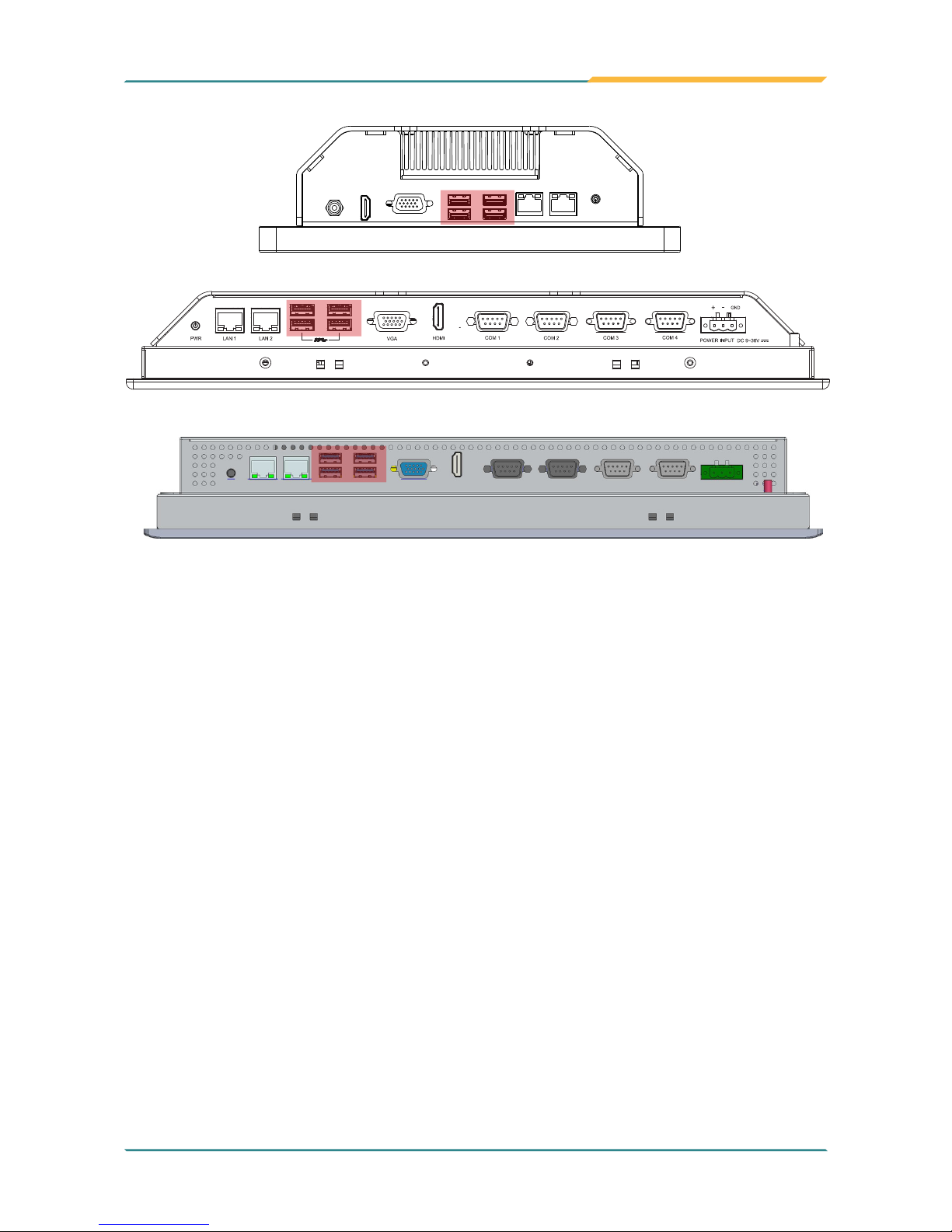
2.2.2. Top/Bottom View
ASLAN-W910C/912C
①②③④⑤⑥
⑦⑧⑨ ⑨

- 12 -
Getting Started
No. Description
①
Power button
②
2 x RJ-45 GbE ports
③
4 x Type-A USB 3.0/2.0 ports
④
VGA port
⑤
HDMI port
⑥
Power jack
⑦
COM1 , RS-232/422/485 selectable
⑧
COM2, RS-232/422/485 selectable
⑨
2 x SMA antenna holes for optional WiFi function
ASLAN-W915C/919C/922C
VGA
HDMI
LAN 2
LAN 1
PWR
DC 9~36V
POWER INPUT
COM 1
COM 2
COM 3
COM 4
GND
-
+
①②③④⑤⑥⑦⑧⑩
⑨
⑪⑪
ASLAN-917X
①②③④⑤⑥⑦⑧⑩
⑨
⑪⑪

- 13 -
Getting Started
No. Description
①
3-pin DC-in power receptacle
②
COM4, RS-232/422/485 selectable
③
COM3, RS-232/422/485 selectable
④
COM2, RS-232/422/485 selectable
⑤
COM1, RS-232/422/485 selectable
⑥
HDMI port
⑦
VGA port
⑧
4 x Type-A USB 3.0/2.0 ports
⑨
2 x RJ-45 GbE ports
⑩
Power button
⑪
2 x SMA Antenna Holes for optional WiFi Function
2.3. Driver Installation Note
The computer supports the operating systems Windows 7, Windows 8.1 and
Windows10. Find the necessary device drivers on the CD that comes with your
purchase. Always follow the sequence below to install all drivers to prevent
errors:
Windows 7 and Windows 8.1 64-Bit
For Windows 7 and 8.1 64-bit, please use system image to install the OS and
the drivers.
Windows 10 64-Bit
Device Driver Path
Chipset \Chipset_INF\Chipset_10.1.1.14_Public\SetupChipset.exe
Ethernet \Ethernet\Win10\PROWin64.exe
Graphic \Graphic\64bit\win64_154025.4463.exe
Audio \Audio\64bit\0006-64bit_Win7_Win8_Win81_Win10_R279.exe
ME \ME_11.0_Corporate_11.0.0.1177\SetupME.exe
RAID
\Intel Rapid Storage Technology Driver (for RAID)\Intel Rapid Storage
Technology Driver 14.8.0.1042\SetupRST.exe

- 14 -
This page is intentionally left blank.

- 15 -
3Chapter 3
Engine of the
Computer
Chapter 3 - Engine of the Computer

- 16 -
Engine of the Computer
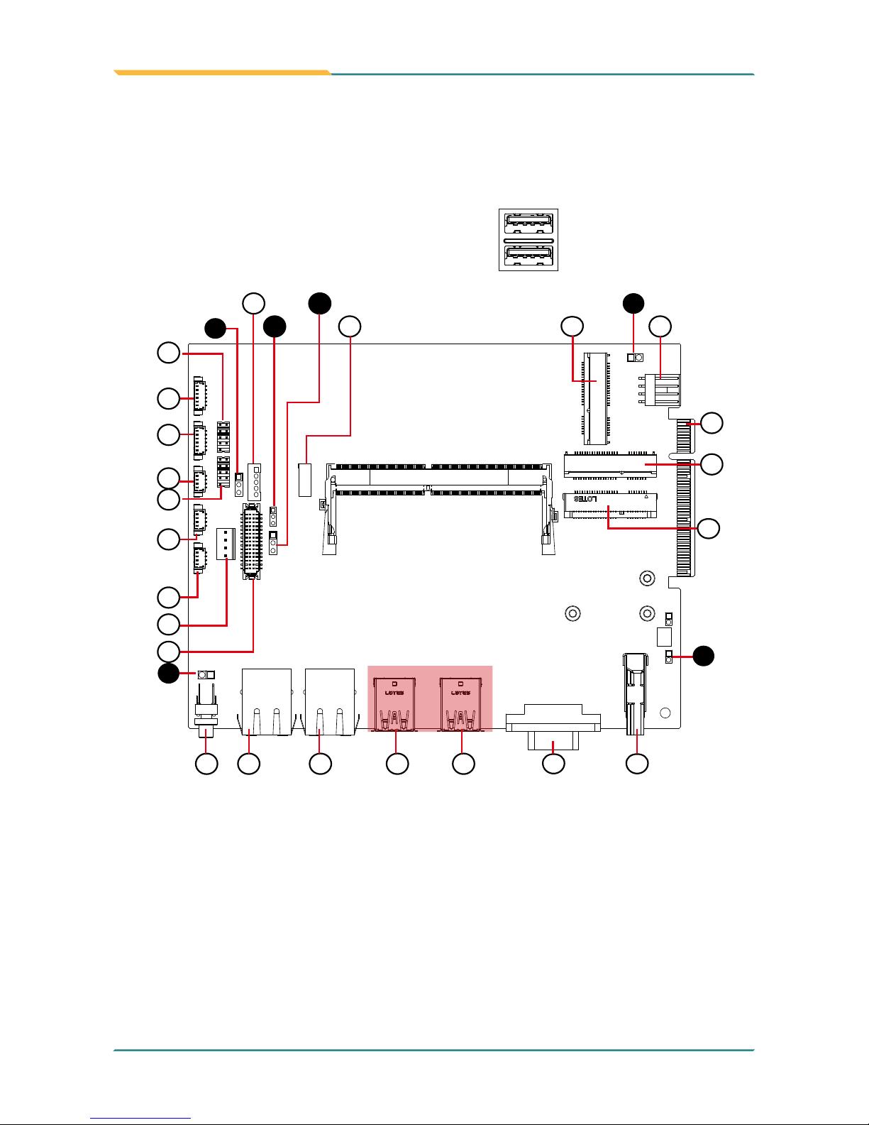
3.1. Board Layout
Main Board (FMB-i89U1)
JBAT1
JBAT2
JSW1
JSW2
JVIN1
1
JVOUT1
JVLCD1
CN2
CN3
CN4
CN6
CN7
CN1
CN5
JME1
1
1
1
LVDS1
JINV1
INV1
1
1
1
1
1
DGP1
2
9
10
JME1
JINV1
INV1
CN1
CN6
CN5
CN7
LVDS1
CN2
CN3
CN4
JVLCD1
DGP1
MC2
GIF1
MC1
MSATA1
JVIN1
JSW2
JSW1
SW1 LCN1 LCN2 USB1 USB2 VGA1 HDMI1
JBAT1
14
15 16
17
2
11
12
13
3
4
1
2
3
4
6
1
18
20
21
19
10
8
9
5
6
7
5
22
23

- 17 -
Engine of the Computer
Jumpers
Label Description
➊JINV1
LVDS Inverter Voltage Select Jumper
➋JME1
ME FLASH Select Jumper
➌JVLCD1
LVDS VDD Voltage Select Jumper
➍JSW1
Power Button
➎JSW2
Reset Button
➏JBAT1
CMOS Settings
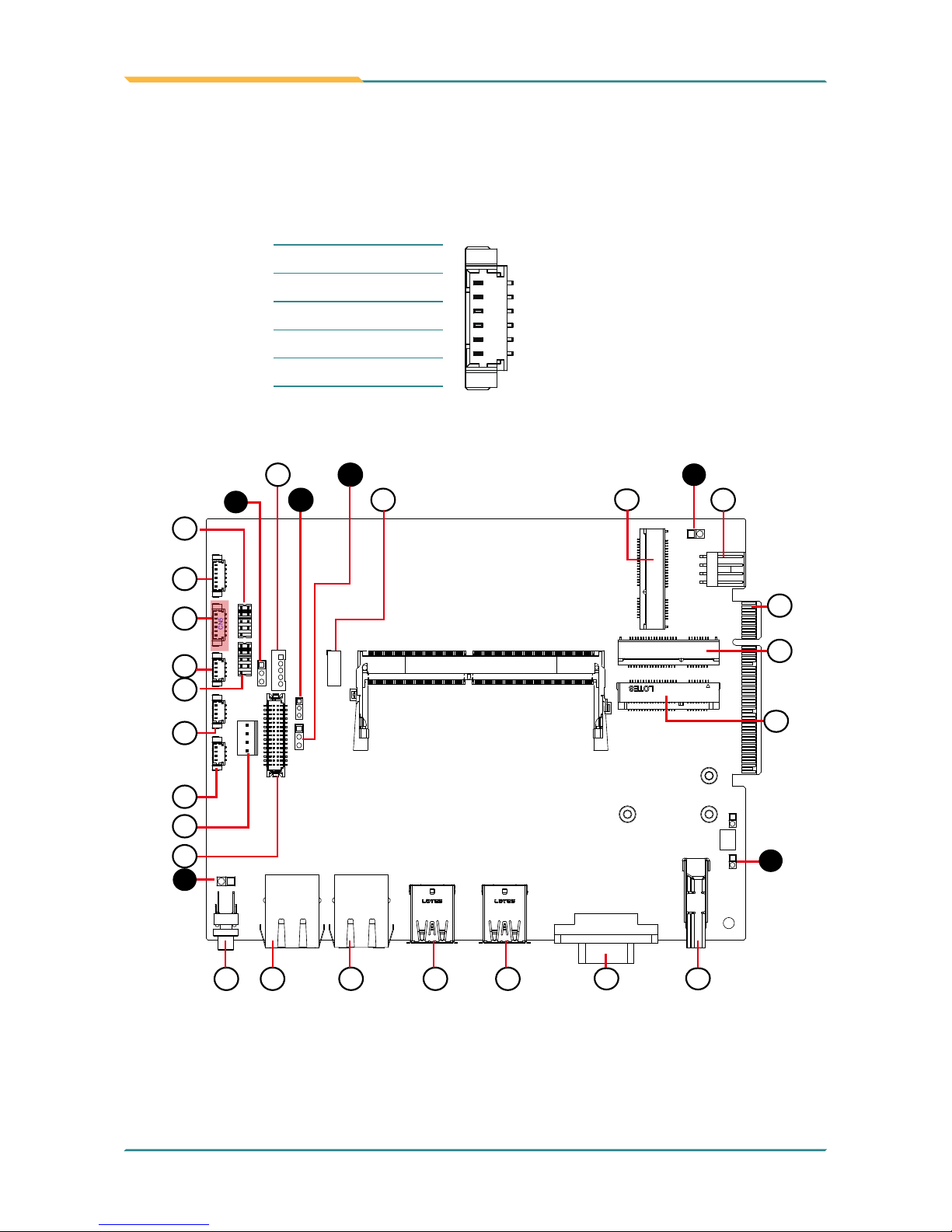
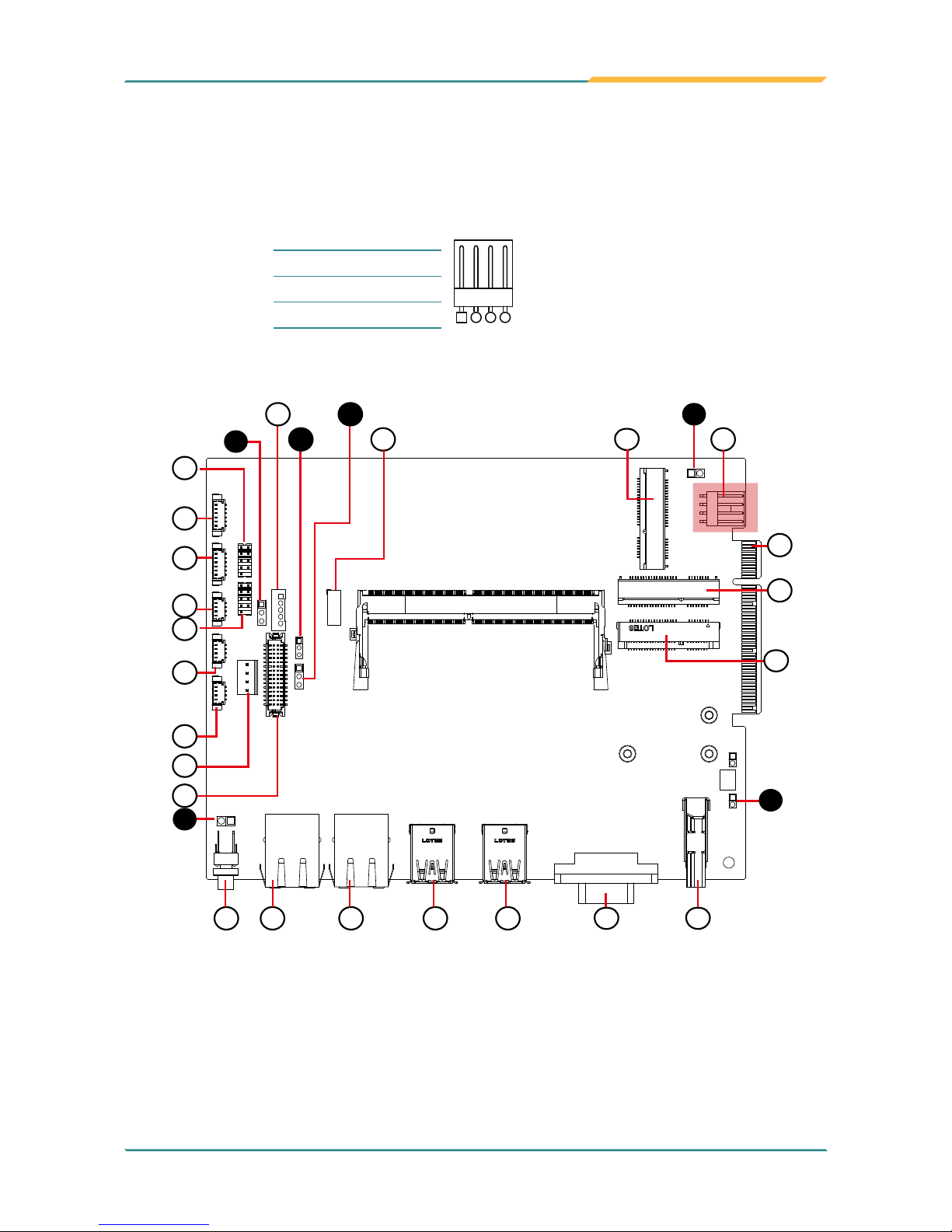
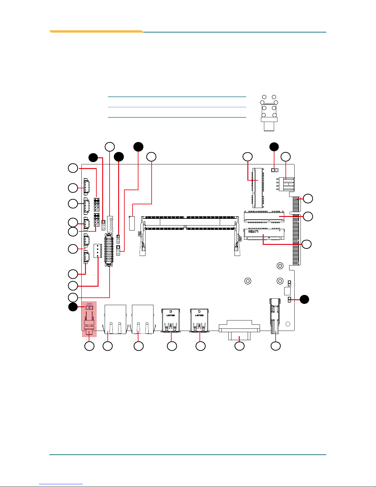
Connectors
Label Description
①CN1
Audio
Connector
②③④CN2, 3, 4
USB 2.0 Connectors
⑤CN5
PS2 Connector
⑥⑦CN6, 7
COM1, 2 (RS-232/422-485 Selectable Serial Port)
⑧JVOUT1
Power Output
⑨LVDS1
LVDS Connector
⑩INV1
LVDS BL Connector
⑪DGP1
Debug Port
⑫JVIN1
Power Input
⑬SW1
Power Button
⑭⑮LCN1, 2
RJ-45 Ethernet Connectors
⑯⑰USB1, 2
USB 3.0/2.0 Connectors
⑱VGA1
VGA Connector
⑲HDMI1
HDMI Connector
⑳
21
MC1, 2
PCI Express Mini-card Full/Half Size Socket
22
MSATA1
mSATA Socket
23
GIF1
PCIe Gold Finger Connector

- 18 -
Engine of the Computer
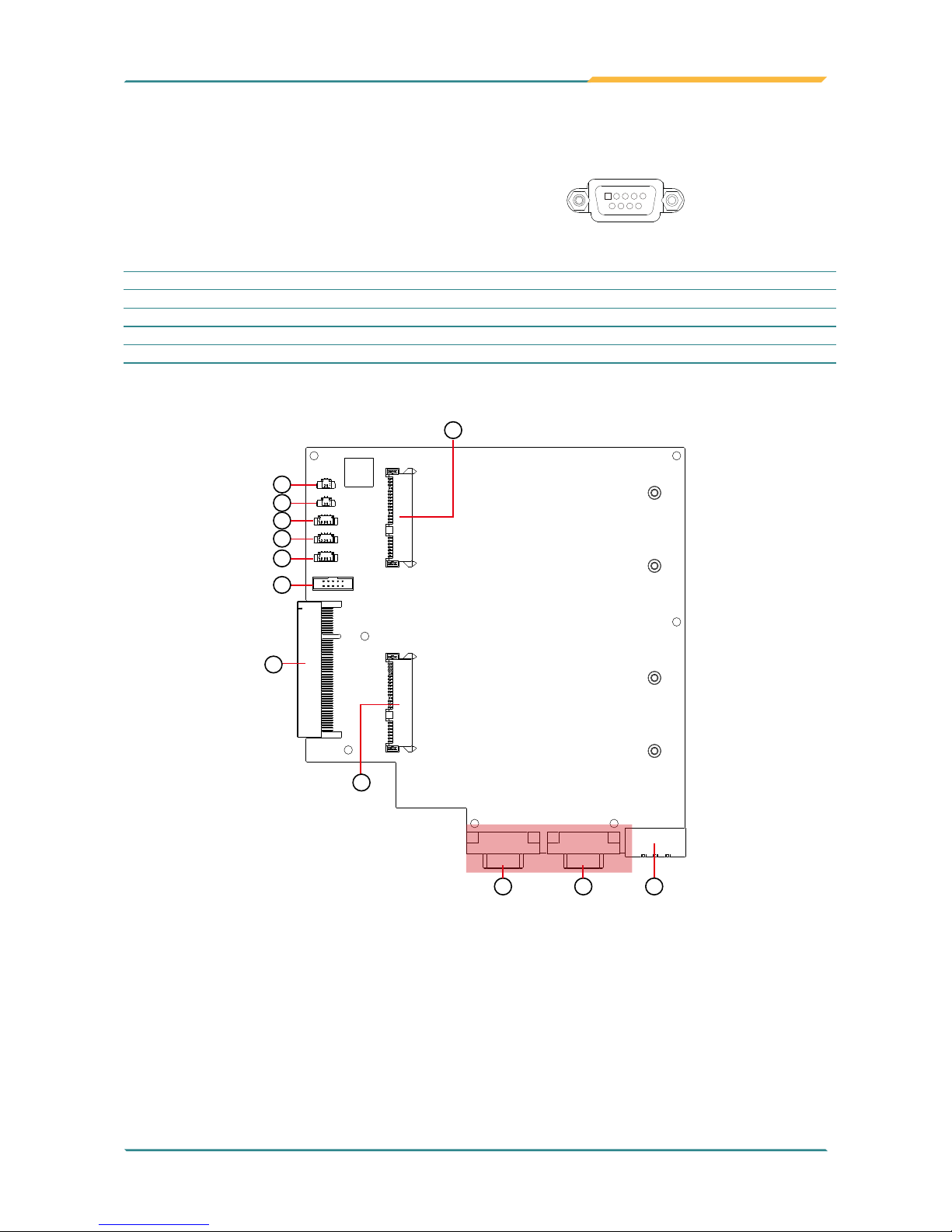
Daughter Board (SCDB-1299H)
The daughter board is only available to ASLAN-917X/W915C/919C/922C/922C-IP.
1 4
1
2
9
10
1
2
8
11
3
4
5
6
7
SPKL1
SPKR1
CN2
CN1
CN3
CN7
SATA 2
SATA 1
GIF1
CN5 CN6 PWRIN1
1
9
10
12
Connectors
Label Description
①PWRIN1
Audio Connector
②③CN6, 5
COM4, 3 (RS-232/422/485 Selectable Serial Port)
④SPKR1
Speaker Output Connector
⑤SPKL1
Speaker Output Connector
⑥⑦⑧CN3, 2, 1
USB 3.0/2.0 Connector
⑨CN7
DIO Connector
⑩GIF1
Gold Finger Connector
⑪⑫SATA1
SATA HDD
Connector

- 19 -
Engine of the Computer
3.2. Jumpers and Connectors
3.2.1 Main Board (FMB-i89U1)
3.2.1.1. Jumpers
➊JINV1
Function: Sets LVDS inverter voltage. (This jumper sets the voltage of LVDS connector
INV1, which means this jumper decides the pin 1 of the LVDS connector INV1.)
Jumper Type: 2.54mm pitch, 1x3-pin header
Setting:
Pin Description
1-2 +12V (default)
2 13
2-3 +5V
2 13
JBAT1
JBAT2
JSW1
JSW2
JVIN1
1
JVOUT1
JVLCD1
CN2
CN3
CN4
CN6
CN7
CN1
CN5
JME1
1
1
1
LVDS1
JINV1
INV1
1
1
1
1
1
DGP1
2
9
10
JME1
JINV1
INV1
CN1
CN6
CN5
CN7
LVDS1
CN2
CN3
CN4
JVLCD1
DGP1
MC2
GIF1
MC1
MSATA1
JVIN1
JSW2
JSW1
SW1 LCN1 LCN2 USB1 USB2 VGA1 HDMI1
JBAT1
14
15 16
17
2
11
12
13
3
4
1
2
3
4
6
1
18
20
21
19
10
8
9
5
6
7
5
22
23

- 20 -
Engine of the Computer
➋ JME1
Function: ME Flash Select Jumper
Jumper Type: 2.00mm pitch, 1x3-pin header
Setting:
Pin Description
1-2 ME Flash disable (Default)
2 13
2-3 ME Flash enable
2 13
JBAT1
JBAT2
JSW1
JSW2
JVIN1
1
JVOUT1
JVLCD1
CN2
CN3
CN4
CN6
CN7
CN1
CN5
JME1
1
1
1
LVDS1
JINV1
INV1
1
1
1
1
1
DGP1
2
9
10
JME1
JINV1
INV1
CN1
CN6
CN5
CN7
LVDS1
CN2
CN3
CN4
JVLCD1
DGP1
MC2
GIF1
MC1
MSATA1
JVIN1
JSW2
JSW1
SW1 LCN1 LCN2 USB1 USB2 VGA1 HDMI1
JBAT1
14
15 16
17
2
11
12
13
3
4
1
2
3
4
6
1
18
20
21
19
10
8
9
5
6
7
5
22
23

- 21 -
Engine of the Computer
➌ JVLCD1
Function: LVDS VDD Voltage Select Jumper
Jumper Type: 2.54mm pitch, 1x3-pin header
Setting:
Pin Description
1-2 +3V (default)
2 13
2-3 +5V
2 13
JBAT1
JBAT2
JSW1
JSW2
JVIN1
1
JVOUT1
JVLCD1
CN2
CN3
CN4
CN6
CN7
CN1
CN5
JME1
1
1
1
LVDS1
JINV1
INV1
1
1
1
1
1
DGP1
2
9
10
JME1
JINV1
INV1
CN1
CN6
CN5
CN7
LVDS1
CN2
CN3
CN4
JVLCD1
DGP1
MC2
GIF1
MC1
MSATA1
JVIN1
JSW2
JSW1
SW1 LCN1 LCN2 USB1 USB2 VGA1 HDMI1
JBAT1
14
15 16
17
2
11
12
13
3
4
1
2
3
4
6
1
18
20
21
19
10
8
9
5
6
7
5
22
23

- 22 -
Engine of the Computer
➍ JSW1
Function: Power Button
Connector Type: 2.54 mm pitch 1x2-pin header
Setting:
Pin Desc.
1 2
1 PWR_IN_SW#
2 GND
➎ JSW2
Function: Reset Button
Connector Type: 2.54 mm pitch 1x2-pin header
Setting:
Pin Desc.
1 2
1 RST_SW#
2 GND
JBAT1
JBAT2
JSW1
JSW2
JVIN1
1
JVOUT1
JVLCD1
CN2
CN3
CN4
CN6
CN7
CN1
CN5
JME1
1
1
1
LVDS1
JINV1
INV1
1
1
1
1
1
DGP1
2
9
10
JME1
JINV1
INV1
CN1
CN6
CN5
CN7
LVDS1
CN2
CN3
CN4
JVLCD1
DGP1
MC2
GIF1
MC1
MSATA1
JVIN1
JSW2
JSW1
SW1 LCN1 LCN2 USB1 USB2 VGA1 HDMI1
JBAT1
14
15 16
17
2
11
12
13
3
4
1
2
3
4
6
1
18
20
21
19
10
8
9
5
6
7
5
22
23

- 23 -
Engine of the Computer
➏ JBAT1
Function: Clears/keeps CMOS
Jumper Type: 2.00 mm pitch 1x2-pin header
Setting:
Pin Description
Short Clears CMOS
1 2
Open Keeps CMOS (default)
1 2
JBAT1
JBAT2
JSW1
JSW2
JVIN1
1
JVOUT1
JVLCD1
CN2
CN3
CN4
CN6
CN7
CN1
CN5
JME1
1
1
1
LVDS1
JINV1
INV1
1
1
1
1
1
DGP1
2
9
10
JME1
JINV1
INV1
CN1
CN6
CN5
CN7
LVDS1
CN2
CN3
CN4
JVLCD1
DGP1
MC2
GIF1
MC1
MSATA1
JVIN1
JSW2
JSW1
SW1 LCN1 LCN2 USB1 USB2 VGA1 HDMI1
JBAT1
14
15 16
17
2
11
12
13
3
4
1
2
3
4
6
1
18
20
21
19
10
8
9
5
6
7
5
22
23

- 24 -
Engine of the Computer
3.2.1.1. Connectors
①
CN1
Function: Audio Connector
Connector Type: 1.25mm pitch 1x6 wire to board connector
Pin Assignment:
Pin Desc.
1
1 MIC_L
2 MIC_R
3 GND
4 GND
5 Line Out_L
6 Line Out_R
JBAT1
JBAT2
JSW1
JSW2
JVIN1
1
JVOUT1
JVLCD1
CN2
CN3
CN4
CN6
CN7
CN1
CN5
JME1
1
1
1
LVDS1
JINV1
INV1
1
1
1
1
1
DGP1
2
9
10
JME1
JINV1
INV1
CN1
CN6
CN5
CN7
LVDS1
CN2
CN3
CN4
JVLCD1
DGP1
MC2
GIF1
MC1
MSATA1
JVIN1
JSW2
JSW1
SW1 LCN1 LCN2 USB1 USB2 VGA1 HDMI1
JBAT1
14
15 16
17
2
11
12
13
3
4
1
2
3
4
6
1
18
20
21
19
10
8
9
5
6
7
5
22
23

- 25 -
Engine of the Computer
②③④
CN2, 3, 4
Function: USB 2.0 Connectors
Connector Type: 1.25mm pitch 1x4 wire to board connector
Pin Assignment:
Pin Desc.
1
1 VCC5
2 DATA-
3 DATA+
4 GND
JBAT1
JBAT2
JSW1
JSW2
JVIN1
1
JVOUT1
JVLCD1
CN2
CN3
CN4
CN6
CN7
CN1
CN5
JME1
1
1
1
LVDS1
JINV1
INV1
1
1
1
1
1
DGP1
2
9
10
JME1
JINV1
INV1
CN1
CN6
CN5
CN7
LVDS1
CN2
CN3
CN4
JVLCD1
DGP1
MC2
GIF1
MC1
MSATA1
JVIN1
JSW2
JSW1
SW1 LCN1 LCN2 USB1 USB2 VGA1 HDMI1
JBAT1
14
15 16
17
2
11
12
13
3
4
1
2
3
4
6
1
18
20
21
19
10
8
9
5
6
7
5
22
23
- 26 -
Engine of the Computer
⑤
CN5
Function: PS2 Connector
Connector Type: 1.25mm pitch 1x6 wire to board connector
Pin Assignment:
Pin Desc.
1
1 KDATA
2 GND
3 MDATA
4 KCLK
5 VCC5
6 MCLK
JBAT1
JBAT2
JSW1
JSW2
JVIN1
1
JVOUT1
JVLCD1
CN2
CN3
CN4
CN6
CN7
CN1
CN5
JME1
1
1
1
LVDS1
JINV1
INV1
1
1
1
1
1
DGP1
2
9
10
JME1
JINV1
INV1
CN1
CN6
CN5
CN7
LVDS1
CN2
CN3
CN4
JVLCD1
DGP1
MC2
GIF1
MC1
MSATA1
JVIN1
JSW2
JSW1
SW1 LCN1 LCN2 USB1 USB2 VGA1 HDMI1
JBAT1
14
15 16
17
2
11
12
13
3
4
1
2
3
4
6
1
18
20
21
19
10
8
9
5
6
7
5
22
23

- 27 -
Engine of the Computer
⑥⑦
CN6, CN7 (COM1, COM2)
Function: RS-232/422/485 selectable pin header
Connector Type: 2.00mm pitch 2x5-pin header
Pin Assignment:
Pin Desc. Pin Desc.
1
9
2
10
1 DCD RS-485(D-) RS-422(TX-) 2 RXD RS-485(D+) RS-422(TX+)
3 TXD RS-422(RX+) 4 DTR RS-422(RX-)
5 GND 6 DSR
7 RTS 8 CTS
9 RI 10 N/C
JBAT1
JBAT2
JSW1
JSW2
JVIN1
1
JVOUT1
JVLCD1
CN2
CN3
CN4
CN6
CN7
CN1
CN5
JME1
1
1
1
LVDS1
JINV1
INV1
1
1
1
1
1
DGP1
2
9
10
JME1
JINV1
INV1
CN1
CN6
CN5
CN7
LVDS1
CN2
CN3
CN4
JVLCD1
DGP1
MC2
GIF1
MC1
MSATA1
JVIN1
JSW2
JSW1
SW1 LCN1 LCN2 USB1 USB2 VGA1 HDMI1
JBAT1
14
15 16
17
2
11
12
13
3
4
1
2
3
4
6
1
18
20
21
19
10
8
9
5
6
7
5
22
23

- 28 -
Engine of the Computer
ASLAN-W915C/919C/922C
ASLAN-917X
ASLAN-W910C/912C
COM1 (CN6)
COM1 (CN6)
COM1 (CN6)
COM2 (CN7)
COM2 (CN7)
COM2 (CN7)

- 29 -
Engine of the Computer
⑧
JVOUT1
Function: Power output
Connector Type: 2.54mm pitch 1x4-pin one-wall connector
Pin Assignment:
Pin Desc.
1
4
1 VCC5
2 GND
3 GND
4 VCC12
JBAT1
JBAT2
JSW1
JSW2
JVIN1
1
JVOUT1
JVLCD1
CN2
CN3
CN4
CN6
CN7
CN1
CN5
JME1
1
1
1
LVDS1
JINV1
INV1
1
1
1
1
1
DGP1
2
9
10
JME1
JINV1
INV1
CN1
CN6
CN5
CN7
LVDS1
CN2
CN3
CN4
JVLCD1
DGP1
MC2
GIF1
MC1
MSATA1
JVIN1
JSW2
JSW1
SW1 LCN1 LCN2 USB1 USB2 VGA1 HDMI1
JBAT1
14
15 16
17
2
11
12
13
3
4
1
2
3
4
6
1
18
20
21
19
10
8
9
5
6
7
5
22
23

- 30 -
Engine of the Computer
⑨
LVDS1
Function: LVDS Connector
Connector Type: Onboard 30-pin header
Pin Assignment:
Pin Desc. Pin Desc.
1
2930
2
2 VCC_LCD 1 VCC_LCD
4 LVDS_B_CLK+ 3 LVDS_A_CLK+
6 LVDS_B_CLK- 5 LVDS_A_CLK-
8 GND 7 GND
10 LVDS_B0+ 9 LVDS_A0+
12 LVDS_B0- 11 LVDS_A0-
14 GND 13 GND
16 LVDS_B1+ 15 LVDS_A1+
18 LVDS_B1- 17 LVDS_A1-
20 GND 19 GND
22 LVDS_B2+ 21 LVDS_A2+
24 LVDS_B2- 23 LVDS_A2-
26 GND 25 GND
28 LVDS_B3+ 27 LVDS_A3+
30 LVDS_B3- 29 LVDS_A3-
JBAT1
JBAT2
JSW1
JSW2
JVIN1
1
JVOUT1
JVLCD1
CN2
CN3
CN4
CN6
CN7
CN1
CN5
JME1
1
1
1
LVDS1
JINV1
INV1
1
1
1
1
1
DGP1
2
9
10
JME1
JINV1
INV1
CN1
CN6
CN5
CN7
LVDS1
JVOUT1
CN2
CN3
CN4
JVLCD1
DGP1
MC2
GIF1
MC1
MSATA1
JVIN1
JSW2
JSW1
SW1 LCN1 LCN2 USB1 USB2 VGA1 HDMI1
JBAT1
14
15 16
17
2
11
12
13
3
4
1
2
3
4
6
1
18
20
21
19
10
8
9
5
6
7
5
22
23

- 31 -
Engine of the Computer
⑩
INV1
Function: LVDS BL Connector
Connector Type: 2.00mm pitch 1x5-pin one-wall connector
Pin Assignment:
Pin Description
1
1 VCC_INV
2 GND
3 LVDS_BKLT_EN
4 LVDS_BKLTCTL
5
GND
JBAT1
JBAT2
JSW1
JSW2
JVIN1
1
JVOUT1
JVLCD1
CN2
CN3
CN4
CN6
CN7
CN1
CN5
JME1
1
1
1
LVDS1
JINV1
INV1
1
1
1
1
1
DGP1
2
9
10
JME1
JINV1
INV1
CN1
CN6
CN5
CN7
LVDS1
CN2
CN3
CN4
JVLCD1
DGP1
MC2
GIF1
MC1
MSATA1
JVIN1
JSW2
JSW1
SW1 LCN1 LCN2 USB1 USB2 VGA1 HDMI1
JBAT1
14
15 16
17
2
11
12
13
3
4
1
2
3
4
6
1
18
20
21
19
10
8
9
5
6
7
5
22
23

- 32 -
Engine of the Computer
⑪
DGP1
Function: Debug port
Connector Type: 2.00mm-pitch 2x5-pin header
Pin Assignment:
Pin Description Pin Description
1 2
9 10
1 24MHz Clock 2 GND
3 LPC_FRAME# 4 LPC_LAD0
5 PLTRST# 6 N.C
7 LPC_LAD3 8 LPC_LAD2
9 VCC3 10 LPC_LAD1
JBAT1
JBAT2
JSW1
JSW2
JVIN1
1
JVOUT1
JVLCD1
CN2
CN3
CN4
CN6
CN7
CN1
CN5
JME1
1
1
1
LVDS1
JINV1
INV1
1
1
1
1
1
DGP1
2
9
10
JME1
JINV1
INV1
CN1
CN6
CN5
CN7
LVDS1
CN2
CN3
CN4
JVLCD1
DGP1
MC2
GIF1
MC1
MSATA1
JVIN1
JSW2
JSW1
SW1 LCN1 LCN2 USB1 USB2 VGA1 HDMI1
JBAT1
14
15 16
17
2
11
12
13
3
4
1
2
3
4
6
1
18
20
21
19
10
8
9
5
6
7
5
22
23
- 33 -
Engine of the Computer
⑫ JVIN1
Function: Power Input Connector
Connector Type: 2.54mm pitch 1x4-pin wafer connector
Pin Assignment:
Pin Desc.
1
1 VCC
2 VCC
3 GND
4 GND
JBAT1
JBAT2
JSW1
JSW2
JVIN1
1
JVOUT1
JVLCD1
CN2
CN3
CN4
CN6
CN7
CN1
CN5
JME1
1
1
1
LVDS1
JINV1
INV1
1
1
1
1
1
DGP1
2
9
10
JME1
JINV1
INV1
CN1
CN6
CN5
CN7
LVDS1
CN2
CN3
CN4
JVLCD1
DGP1
MC2
GIF1
MC1
MSATA1
JVIN1
JSW2
JSW1
SW1 LCN1 LCN2 USB1 USB2 VGA1 HDMI1
JBAT1
14
15 16
17
2
11
12
13
3
4
1
2
3
4
6
1
18
20
21
19
10
8
9
5
6
7
5
22
23
- 34 -
Engine of the Computer
⑬
SW1
Function Power Button
Connector Type: LED tact switch with green and red colors
Pin Assignment:
Pin Description Pin Description
1 3
2
4
L1
L2
1 GND 2 N/A
3 BTN 4 N/A
L1 SW1_LED_N L2 SW1_LED_P
JBAT1
JBAT2
JSW1
JSW2
JVIN1
1
JVOUT1
JVLCD1
CN2
CN3
CN4
CN6
CN7
CN1
CN5
JME1
1
1
1
LVDS1
JINV1
INV1
1
1
1
1
1
DGP1
2
9
10
JME1
JINV1
INV1
CN1
CN6
CN5
CN7
LVDS1
CN2
CN3
CN4
JVLCD1
DGP1
MC2
GIF1
MC1
MSATA1
JVIN1
JSW2
JSW1
SW1 LCN1 LCN2 USB1 USB2 VGA1 HDMI1
JBAT1
14
15 16
17
2
11
12
13
3
4
1
2
3
4
6
1
18
20
21
19
10
8
9
5
6
7
5
22
23

- 35 -
Engine of the Computer
ASLAN-917X
ASLAN-W915C/919C/922C
ASLAN-W910C/912C

- 36 -
Engine of the Computer
⑭⑮ LCN1, 2
Function: RJ-45 Ethernet connectors
Connector Type: RJ-45 connector that supports 10/100/1000Mbps fast Ethernet
Pin Assignment:
The pin assignments conform to the
industry standard.
1 8
JBAT1
JBAT2
JSW1
JSW2
JVIN1
1
JVOUT1
JVLCD1
CN2
CN3
CN4
CN6
CN7
CN1
CN5
JME1
1
1
1
LVDS1
JINV1
INV1
1
1
1
1
1
DGP1
2
9
10
JME1
JINV1
INV1
CN1
CN6
CN5
CN7
LVDS1
CN2
CN3
CN4
JVLCD1
DGP1
MC2
GIF1
MC1
MSATA1
JVIN1
JSW2
JSW1
SW1 LCN1 LCN2 USB1 USB2 VGA1 HDMI1
JBAT1
14
15 16
17
2
11
12
13
3
4
1
2
3
4
6
1
18
20
21
19
10
8
9
5
6
7
5
22
23

- 37 -
Engine of the Computer
ASLAN-917X
ASLAN-W915C/919C/922C
ASLAN-W910C/912C
- 38 -
Engine of the Computer
⑯
⑰ USB1, 2
Function: USB 3.0/2.0 Connectors
Connector Type: Double-stacked Type-A USB connectors
Pin Assignment:
The pin assignments conform to the
industry standard.
JBAT1
JBAT2
JSW1
JSW2
JVIN1
1
JVOUT1
JVLCD1
CN2
CN3
CN4
CN6
CN7
CN1
CN5
JME1
1
1
1
LVDS1
JINV1
INV1
1
1
1
1
1
DGP1
2
9
10
JME1
JINV1
INV1
CN1
CN6
CN5
CN7
LVDS1
CN2
CN3
CN4
JVLCD1
DGP1
MC2
GIF1
MC1
MSATA1
JVIN1
JSW2
JSW1
SW1 LCN1 LCN2 USB1 USB2 VGA1 HDMI1
JBAT1
14
15 16
17
2
11
12
13
3
4
1
2
3
4
6
1
18
20
21
19
10
8
9
5
6
7
5
22
23
- 39 -
Engine of the Computer
ASLAN-917X
ASLAN-W915C/919C/922C
ASLAN-W910C/912C

- 40 -
Engine of the Computer
⑱
VGA1
Function: VGA Connector
Connector Type: D-Sub 15-pin female connector
Pin Assignment:
Pin Description Pin Description
1 RED 9 5V
2 GREEN 10 GND
3 BLUE 11 N/C
4 N/C 12 D-DATA
5 GND 13 H-SYNC
6 GND 14 V-SYNC
7 GND 15 D-DCLK
8 GND
JBAT1
JBAT2
JSW1
JSW2
JVIN1
1
JVOUT1
JVLCD1
CN2
CN3
CN4
CN6
CN7
CN1
CN5
JME1
1
1
1
LVDS1
JINV1
INV1
1
1
1
1
1
DGP1
2
9
10
JME1
JINV1
INV1
CN1
CN6
CN5
CN7
LVDS1
CN2
CN3
CN4
JVLCD1
DGP1
MC2
GIF1
MC1
MSATA1
JVIN1
JSW2
JSW1
SW1 LCN1 LCN2 USB1 USB2 VGA1 HDMI1
JBAT1
14
15 16
17
2
11
12
13
3
4
1
2
3
4
6
1
18
20
21
19
10
8
9
5
6
7
5
22
23

- 41 -
Engine of the Computer
ASLAN-917X
ASLAN-W915C/919C/922C
ASLAN-W910C/912C

- 42 -
Engine of the Computer
⑲
HDMI1
Function: HDMI connector
Connector Type: 19-pin HDMI connector with ange
Pin Assignment:
The pin assignments conform to the
industry standard.
18
1
2
19
JBAT1
JBAT2
JSW1
JSW2
JVIN1
1
JVOUT1
JVLCD1
CN2
CN3
CN4
CN6
CN7
CN1
CN5
JME1
1
1
1
LVDS1
JINV1
INV1
1
1
1
1
1
DGP1
2
9
10
JME1
JINV1
INV1
CN1
CN6
CN5
CN7
LVDS1
CN2
CN3
CN4
JVLCD1
DGP1
MC2
GIF1
MC1
MSATA1
JVIN1
JSW2
JSW1
SW1 LCN1 LCN2 USB1 USB2 VGA1 HDMI1
JBAT1
14
15 16
17
2
11
12
13
3
4
1
2
3
4
6
1
18
20
21
19
10
8
9
5
6
7
5
22
23

- 43 -
Engine of the Computer
ASLAN-917X
ASLAN-W915C/919C/922C
ASLAN-W910C/912C

- 44 -
Engine of the Computer
⑳21 MC1, 2
Function: MC1: PCI Express Mini-card Full Size socket
MC2: PCI Express Mini-card Half Size socket
Connector Type: Onboard 0.8mm pitch 52-pin edge card connector
Pin Assignment: The pin assignments conform to the industry standard.
52
51
16 18
15
17
2
1
52
51
16 18
15
17
2
1
MC1 MC2
JBAT1
JBAT2
JSW1
JSW2
JVIN1
1
JVOUT1
JVLCD1
CN2
CN3
CN4
CN6
CN7
CN1
CN5
JME1
1
1
1
LVDS1
JINV1
INV1
1
1
1
1
1
DGP1
2
9
10
JME1
JINV1
INV1
CN1
CN6
CN5
CN7
LVDS1
CN2
CN3
CN4
JVLCD1
DGP1
MC2
GIF1
MC1
MSATA1
JVIN1
JSW2
JSW1
SW1 LCN1 LCN2 USB1 USB2 VGA1 HDMI1
JBAT1
14
15 16
17
2
11
12
13
3
4
1
2
3
4
6
1
18
20
21
19
10
8
9
5
6
7
5
22
23

- 45 -
Engine of the Computer
22
MSATA1
Function: mSATA socket
Connector Type: Onboard 0.8mm pitch 52-pin edge card connector
Pin Assignment: The pin assignments conform to the industry standard.
1
2
17
15
18
16
51
52
JBAT1
JBAT2
JSW1
JSW2
JVIN1
1
JVOUT1
JVLCD1
CN2
CN3
CN4
CN6
CN7
CN1
CN5
JME1
1
1
1
LVDS1
JINV1
INV1
1
1
1
1
1
DGP1
2
9
10
JME1
JINV1
INV1
CN1
CN6
CN5
CN7
LVDS1
CN2
CN3
CN4
JVLCD1
DGP1
MC2
GIF1
MC1
MSATA1
JVIN1
JSW2
JSW1
SW1 LCN1 LCN2 USB1 USB2 VGA1 HDMI1
JBAT1
14
15 16
17
2
11
12
13
3
4
1
2
3
4
6
1
18
20
21
19
10
8
9
5
6
7
5
22
23

- 46 -
Engine of the Computer
23
GIF1
Function: Gold Finger Connector for Daughter Board
Connector Type: Onboard 49-pin Golden Finger
Pin Assignment:
Pin Desc. Pin Desc. Pin Desc. Pin Desc.
A1 NC A26 NC B1 +12VAUX B26 GND
A2 +12VAUX A27 GND B2 +12VAUX B27 NC
A3 +12VAUX A28 GND B3 +12VAUX B28 NC
A4 GND A29 NC B4 GND B29 GND
A5 LPC_LAD0 A30 NC B5 SMBCLK_PCIE B30 NC
A6 LPC_LAD1 A31 GND B6 SMBDATA_PCIE B31 NC
A7 LPC_LAD2 A32 NC B7 GND B32 GND
A8 LPC_LAD3 A33 NC B8 NC B33 NC
A9 NC A34 GND B9 LPC_FRAME# B34 NC
A10 NC A35 NC B10 NC B35 GND
A11 BUF_PLTRST# A36 NC B11 PCIE_WAKE# B36 GND
A12 GND A37 GND B12 LPC_SERIRQ B37 SATA0_TX+
A13 NC A38 GND B13 GND B38 SATA0_TX-
A14 NC A39 SATA1_TX+ B14 NC B39 GND
A15 GND A40 SATA1_TX- B15 NC B40 GND
A16 NC A41 GND B16 GND
B41 SATA0_RX+
A17 NC A42 GND B17 NC B42 SATA0_RX-
A18 GND A43 SATA1_RX+ B18 GND B43 GND
A19 CLK_24M_GF A44 SATA1_RX- B19 NC B44 GND
A20 GND A45 GND B20 NC B45 USB2_1+
A21 NC A46 GND B21 GND B46 USB2_1-
A22 NC A47 NC B22 GND B47 GND
A23 GND A48 NC B23 NC B48 PS_ON#
A24 GND A49 GND B24 NC B49 GND
A25 NC B25 GND

- 47 -
Engine of the Computer
JBAT1
JBAT2
JSW1
JSW2
JVIN1
1
JVOUT1
JVLCD1
CN2
CN3
CN4
CN6
CN7
CN1
CN5
JME1
1
1
1
LVDS1
JINV1
INV1
1
1
1
1
1
DGP1
2
9
10
JME1
JINV1
INV1
CN1
CN6
CN5
CN7
LVDS1
CN2
CN3
CN4
JVLCD1
DGP1
MC2
GIF1
MC1
MSATA1
JVIN1
JSW2
JSW1
SW1 LCN1 LCN2 USB1 USB2 VGA1 HDMI1
JBAT1
14
15 16
17
2
11
12
13
3
4
1
2
3
4
6
1
18
20
21
19
10
8
9
5
6
7
5
22
23

- 48 -
Engine of the Computer
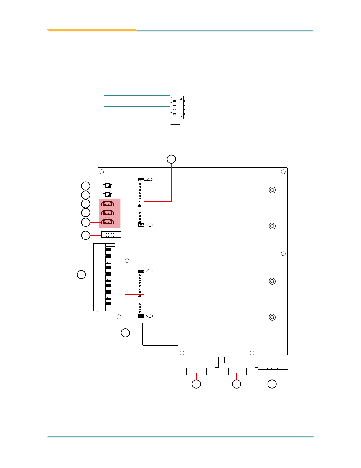
3.2.2 Daughter Board (SCB-1299H)
The daughter board is only available to ASLAN-917X/W915C/919C/922C/922C-IP.
① PWRIN1
Function: DC Adapter Power Input
Connector Type: 1x3-pin Terminal block
Pin Assignment:
Pin Desc.
1 2 3
1 V+
2 V-
3 GND
1 4
1
2
9
10
1
2
8
11
3
4
5
6
7
SPKL1
SPKR1
CN2
CN1
CN3
CN7
SATA 2
SATA 1
GIF1
CN5 CN6 PWRIN1
1
9
10
12
- 49 -
Engine of the Computer
②③ CN6, CN5 (COM4, COM3)
Function: RS-232/422/485 Selectable Serial Port
5
1
6
9
Connector Type: External 9-pin D-sub male connector
Pin Assignment:
RS232 RS422 RS485
Pin Desc Pin Desc Pin Desc Pin Desc Pin Desc Pin Desc
1 DCD 6 DSR 1 COM_422 TX- 6 N/C 1 COM_485 D- 6 N/C
2 RXD 7 RTS 2 COM_422 TX+ 7 N/C 2 COM_485 D+ 7 N/C
3 TXD 8 CTS 3 COM_422 RX+ 8 N/C 3 N/C 8 N/C
4 DTR 9 RI 4 COM_422 RX- 9 N/C 4 N/C 9 N/C
5 GND 5 GND 5 GND
1 4
1
2
9
10
1
2
8
11
3
4
5
6
7
SPKL1
SPKR1
CN2
CN1
CN3
CN7
SATA 2
SATA 1
GIF1
CN5 CN6 PWRIN1
1
9
10
12

- 50 -
Engine of the Computer
ASLAN-917X
ASLAN-W915C/919C/922C
COM3 (CN5)
COM3 (CN5)
COM4 (CN6)
COM4 (CN6)

- 51 -
Engine of the Computer
④⑤ SPKR1, SPKL1
Function: Speaker Output Connector
Connector Type: 1.25mm pitch 1x2 wire to board connector
Pin Assignment:
SPKR1
Pin Desc.
1
1 LOUT-R
2 GND_AU1
SPKL1
1 LOUT-L
2 GND_AU1
1 4
1
2
9
10
1
2
8
11
3
4
5
6
7
SPKL1
SPKR1
CN2
CN1
CN3
CN7
SATA 2
SATA 1
GIF1
CN5 CN6 PWRIN1
1
9
10
12
- 52 -
Engine of the Computer
⑥⑦⑧ CN3, 2, 1
Function: USB 3.0/2.0 Connector
Connector Type: 1.25mm pitch 1x4 wire to board connector
Pin Assignment:
Pin Desc.
1
1 VCC5
2 DATA-
3 DATA+
4 GND
1 4
1
2
9
10
1
2
8
11
3
4
5
6
7
SPKL1
SPKR1
CN2
CN1
CN3
CN7
SATA 2
SATA 1
GIF1
CN5 CN6 PWRIN1
1
9
10
12

- 53 -
Engine of the Computer
⑨ CN7
Function: DIO Connector
Connector Type: 2.0mm pitch 1x4 pin wafer connector
Pin Assignment:
Pin Desc. Pin Desc.
1
2
9
10
1 DIN0 2 DOUT0
3 DIN1 4 DOUT1
5 DIN2 6 DOUT2
7 DIN3 8 DOUT3
9 N/C 10 N/C
1 4
1
2
9
10
1
2
8
11
3
4
5
6
7
SPKL1
SPKR1
CN2
CN1
CN3
CN7
SATA 2
SATA 1
GIF1
CN5 CN6 PWRIN1
1
9
10
12

- 54 -
Engine of the Computer
⑩ GIF1
Function: Connector for Main Board
Connector Type: Onboard 49-pin Connector
Pin Assignment:
Pin Desc. Pin Desc. Pin Desc. Pin Desc.
A1 NC A26 NC B1 +12VAUX B26 GND
A2 +12VAUX A27 GND B2 +12VAUX B27 NC
A3 +12VAUX A28 GND B3 +12VAUX B28 NC
A4 GND A29 NC B4 GND B29 GND
A5 LPC_LAD0 A30 NC B5 SMBCLK_PCIE B30 NC
A6 LPC_LAD1 A31 GND B6 SMBDATA_PCIE B31 NC
A7 LPC_LAD2 A32 NC B7 GND B32 GND
A8 LPC_LAD3 A33 NC B8 NC B33 NC
A9 NC A34 GND B9 LPC_FRAME# B34 NC
A10 NC A35 NC B10 NC B35 GND
A11 BUF_PLTRST# A36 NC B11 PCIE_WAKE# B36 GND
A12 GND A37 GND B12 LPC_SERIRQ B37 SATA0_TX+
A13 NC A38 GND B13 GND B38 SATA0_TX-
A14 NC A39 SATA1_TX+ B14 NC B39 GND
A15 GND A40 SATA1_TX- B15 NC B40 GND
A16 NC A41 GND B16 GND
B41 SATA0_RX+
A17 NC A42 GND B17 NC B42 SATA0_RX-
A18 GND A43 SATA1_RX+ B18 GND B43 GND
A19 CLK_24M_GF A44 SATA1_RX- B19 NC B44 GND
A20 GND A45 GND B20 NC B45 USB2_1+
A21 NC A46 GND B21 GND B46 USB2_1-
A22 NC A47 NC B22 GND B47 GND
A23 GND A48 NC B23 NC B48 PS_ON#
A24 GND A49 GND B24 NC B49 GND
A25 NC B25 GND

- 55 -
Engine of the Computer
1 4
1
2
9
10
1
2
8
11
3
4
5
6
7
SPKL1
SPKR1
CN2
CN1
CN3
CN7
SATA 2
SATA 1
GIF1
CN5 CN6 PWRIN1
1
9
10
12

- 56 -
Engine of the Computer
⑪⑫ SATA1, SATA2
Function: SATA HDD connector
Connector Type: SATA port with data +power vertical connector (7+15pin)
Pin Assignment:
Pin Desc. Pin Desc. Pin Desc.
P1
P15
S7
S1
S1 GND P1 3.3V P8 5V
S2 TX+ P2 3.3V P9 5V
S3 TX- P3 3.3V P10 GND
S4 GND P4 GND P11 NC
S5 RX- P5 GND P12 GND
S6 RX+ P6 GND P13 NC
S7 GND P7 5V P14 NC
P15 NC
1 4
1
2
9
10
1
2
8
11
3
4
5
6
7
SPKL1
SPKR1
CN2
CN1
CN3
CN7
SATA 2
SATA 1
GIF1
CN5 CN6 PWRIN1
1
9
10
12

- 57 -
4Chapter 4
Installation &
Maintenance
Chapter 4 - Installation and Maintenance

- 58 -
Installation & Maintenance
4.1. Disassembly the Computer
The computer’s carrier board comes with some connectors to join some
devices and also some jumpers to alter hardware conguration. Follow through
the guide below to access these components inside the computer.
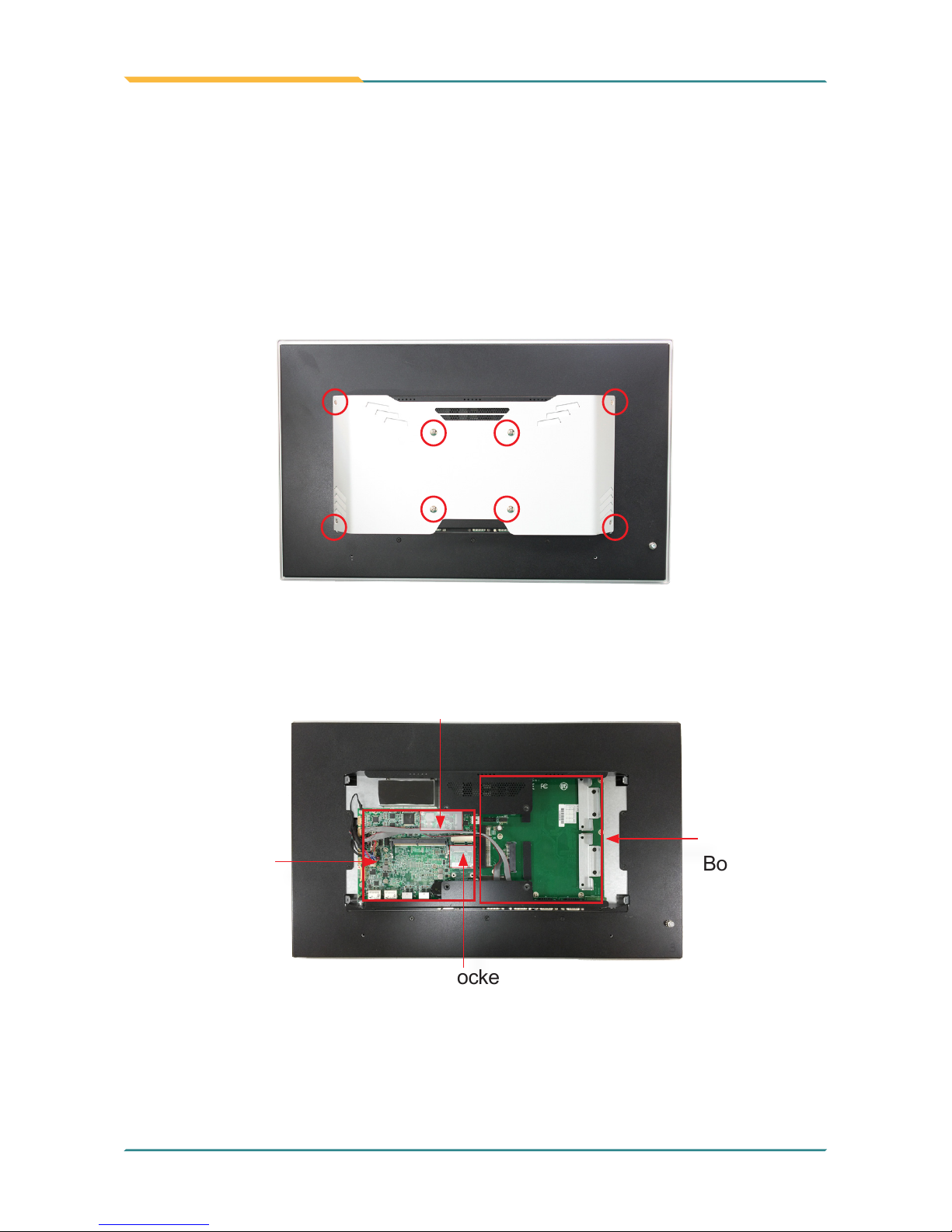
4.1.1 ASLAN-W910C/912C
The ASLAN-W910C/W912C comes with a main board inside. The disassembly
procedures for these two models are similar. This section will use the ASLANW910C to illustrate the procedures.
1. Loosen and remove the 8 screws from the computer’s rear side. Then,
loosen and remove the COM/VGA port screws from the top and bottom side
of the computer.
2. Dismount the rear cover from the computer. The inside of the computer
comes to view. With the bottom side facing you, lift up the bottom side of the
main board and disconnect the three connectors as shown below.

- 59 -
Installation & Maintenance
3. Carefully lift the main board and set it aside on a at surface.
4. Then you are ready to access the components of the computer.
Mini-card socket
for Wi-Fi module
Mini-card socket
- 60 -
Installation & Maintenance
4.1.2. ASLAN-917X/W915C/919C/922C
The ASLAN-917X/W915C/W919C/W922C come with a main board and a
daughter board inside. The disassembly procedures for these models are
similar. This section will use the ASLAN-W922C to illustrate the procedures.
1. Loosen and remove the 8 screws from the computer’s rear side.
2. Dismount the rear cover from the computer. The inside of the computer
comes to view.
Mini-card socket for Wi-Fi module
Mini-card socket
Main Board
Daughter
Board

- 61 -
Installation & Maintenance
4.2. Install Hardware
4.2.1. Install Wi-Fi Module
The computer comes with one Mini-card socket to load the computer with a
wireless module of PCI Express Mini-card form factor: This section will guide you
to install the Wi-Fi module.
1. Locate the PCI Express Mini-card socket for wireless module.
Mini-card socket
for Wi-Fi module
Note the socket has a break among the connector .
The module's key notch should meet
the connector's break.

- 62 -
Installation & Maintenance
2. Prepare the Wi-Fi module kit. The module is a half-size module of PCI
Express Mini-card form factor, with two U.FL connectors, one is “MAIN“,
and the other is “AUX“.
Two U.FL connectors, one
is “MAIN” (marked 0), the
other is “AUX” (marked 1).
3. Have the RF antenna. The antenna has an SMA connector on one end and
an MHF connector on the other.
SMA connector
MHF connector

- 63 -
Installation & Maintenance
4. Connect the RF antenna’s MHF connector to the Wi-Fi module’s main
connector marked 0. If you are going to connect a secondary antenna,
connect it to the connector marked 1.
Connect the RF antenna’s
MHF connector to the
Wi-Fi module’s main
connector (marked 0)
Connect the secondary RF
antenna’s MHF connector to
the Wi-Fi module’s secondary
connector (marked 1)
5. Plug the Wi-Fi module to the socket’s connector by a slanted angle. Fully
plug the module, and note the notch on the wireless module should meet
the break of the connector.
Fully plug the module.
Connector break
- 64 -
Installation & Maintenance
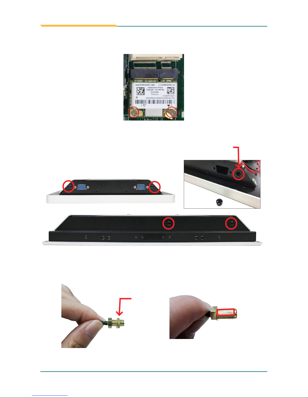
6. Press the module down and x the module in place using two screws.
7. Remove a plastic plug from the computer's bottom (or top) side to make an
antenna hole. Keep the plastic plug for any possible restoration in the future.
the removed
plug
the antenna hole
8. From the other end of the RF antenna, which is an SMA connector, remove
the washer and the nut. Save the washer and nut for later use. Note the SMA
connector has the form of a threaded bolt, with one at side.
Remove
the nut and
washer.
Among the screw
thread, there is a
at side.
- 65 -
Installation & Maintenance
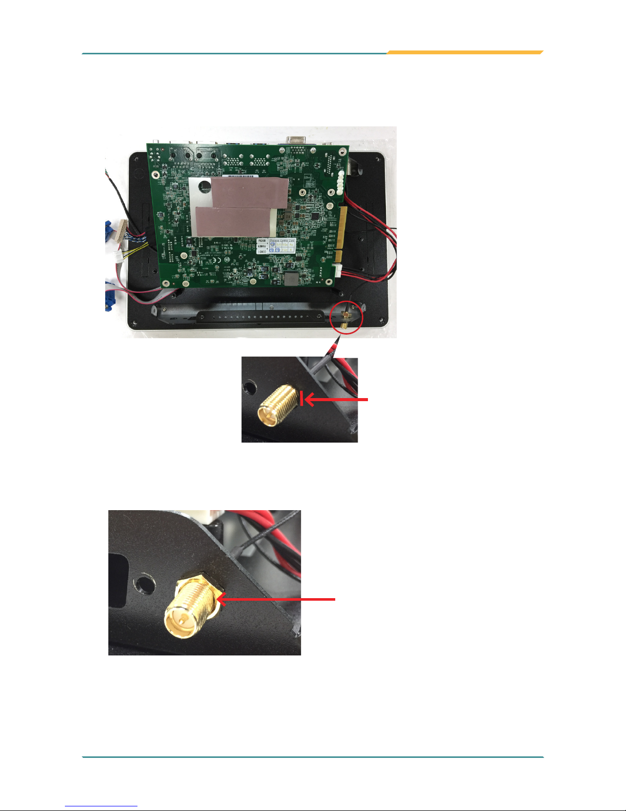
9. Pull the SMA connector through the above mentioned antenna hole. Note to
meet the aforesaid attened side with the antenna hole's at side.
Arrange the at side of the
SMA connector to meet the at
side of the antenna hole.
10. Mount the washer rst and then the nut to the SMA connector. Make sure
the nut is tightened.
Mount the washer and the
nut to the SMA connector.
Tighten the nut.
11. Restore the computer's bottom cover and fasten the screws.

- 66 -
Installation & Maintenance
12. Have the external antenna(s). Screw and tightly fasten the antenna(s) to the
SMA connector.

- 67 -
Installation & Maintenance
4.2.1. Install mSATA Module
To install an mSATA storage module to the computer:
1. Locate the socket for mSATA modules.
mSATA socket
2. Confront the mSATA module’s edge connector with the socket's connector.
Align the module’s key notch the connector's break.
The module's key
notch should meet the
connector's break.

- 68 -
Installation & Maintenance
3. Fully plug the module until it cannot be plugged any more.
Fully plug the module.
Connector
break
4. Press the module down and x the module in place using two screws.

- 69 -
Installation & Maintenance
4.2.1. Install SSD or HDD
The ASLAN-917X/W915C/W919C/W922C comes with two 2.5" drive bays for
2.5” HDD or SSD storage device. To install 2.5” HDD or SSD to the computer,
1. Locate the 2.5" drive bays inside the computer.
2. For the drive bay you want to use, remove the 2 screws securing the bracket.
3. Fix the 2.5” HDD or SSD storage device to the bracket you just removed
using 2 screws coming with the storage device kit.

- 70 -
Installation & Maintenance
4. Slide the storage device into the SATA connector. Then x the bracket using
the 2 screws removed in step 2.
SATA Connector
5. Repeat steps 2 to 5 to install 2.5” HDD or SSD to the other bay.
- 71 -
Installation & Maintenance
4.3. Mount the Computer
Integrate the computer to where it works by mounting it to a wall in the
surroundings or to the rear of a display panel.
4.3.1. Panel Mounting
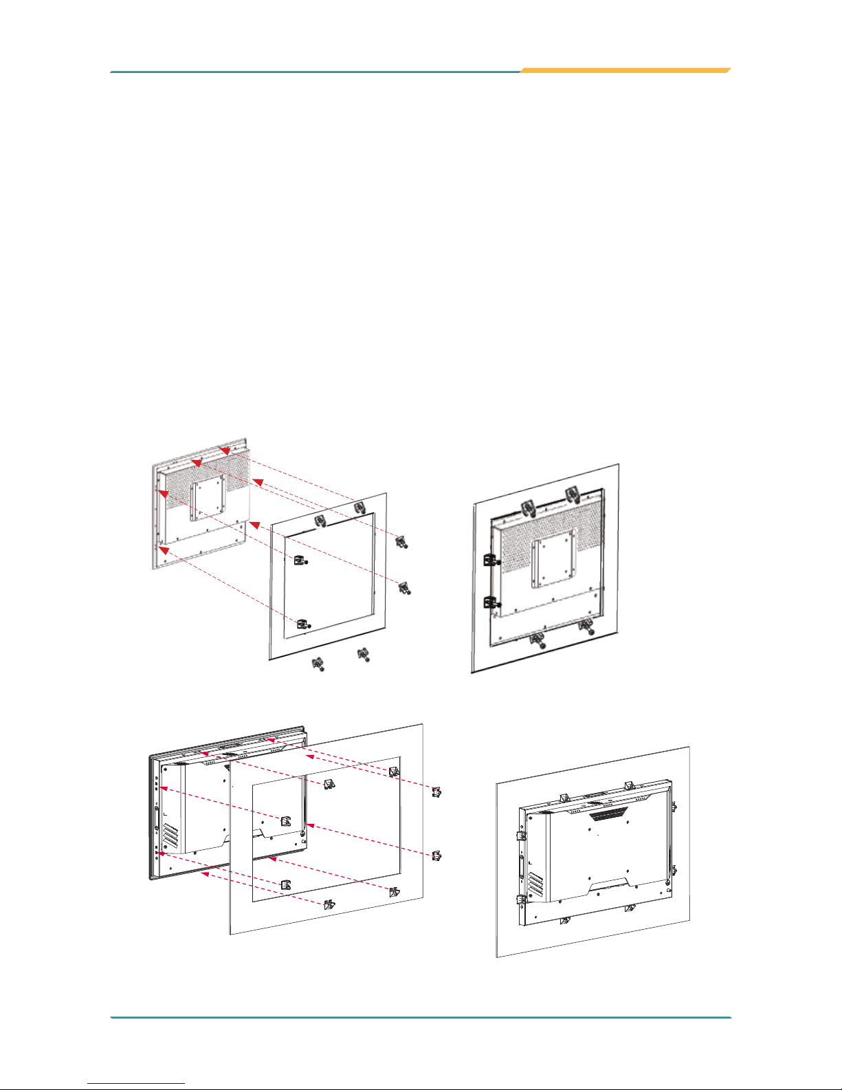
For ASLAN-917X and ASLAN-W915C/919C/922C
1. Put the panel PC into correct-sized opening on a panel or other xture.
2. Put the provided panel-mounting clamps into holes around edges of the
panel PC.
3. Tightly fasten the panel-mounting clamps around edges.
Clamp
Example of ASLAN-917X
Example of ASLAN-W915C/919C/922C
- 72 -
Installation & Maintenance
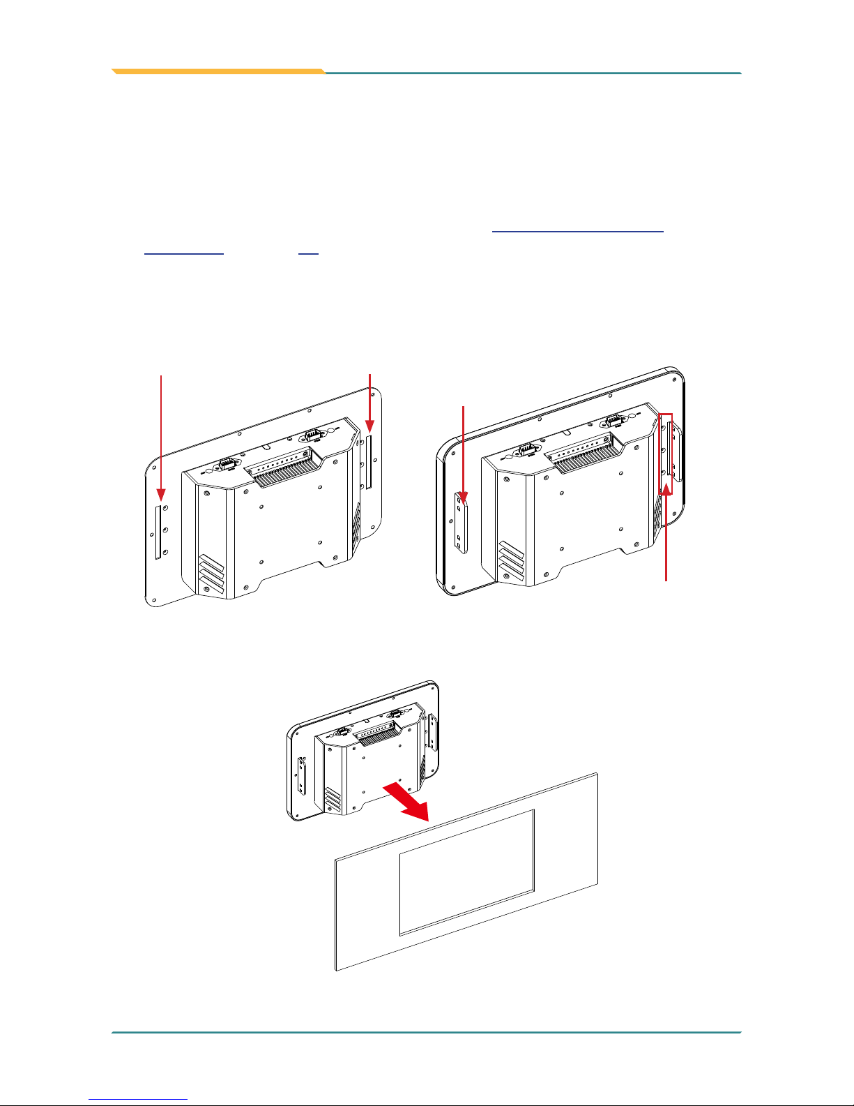
For ASLAN-W910/912C
The ASLAN-W910/912C comes with optional panel mounting brackets for
panel mounting. Follow the steps below to mount the computer on a panel.
1. Disassembly the rear cover as described in 4.1. Disassembly the
Computer on page 58.
2. Remove the cover plate of the holes for the mounting brackets. Secure
the mounting brackets to the rear cover by fastening the 3 screws. Then
restore the rear cover to the computer.
Holes for mounting brackets
3 screws securing
the bracket
Bracket
3. Put the panel PC into correct-sized opening on a panel or other xture.

- 73 -
Installation & Maintenance
4. Put the provided panel-mounting clamps into holes around edges of the
panel PC.
5. Tightly fasten the panel-mounting clamps around edges.

- 74 -
Installation & Maintenance
4.3.2. VESA Mounting
4.3.2.1. Use VESA Arm
To integrate the computer to a VESA arm:
1. Find the VESA mounting holes on the Panel PC. The VESA specications
varies according to your model.
75 x75 mm VESA
mounting holes
100 x 100 mm VESA
mounting holes
2. Attach the VESA arm to the rear of the computer by meeting the mounting
holes on the VESA arm and VESA bracket.
3. Fix the assemblage with four screws.

- 75 -
5Chapter 5
BIOS
Chapter 5 - BIOS

- 76 -
BIOS
The BIOS Setup utility for the ASLAN-W9XXC/917X is featured by American
Megatrends Inc to congure the system settings stored in the system’s BIOS
ROM. The BIOS is activated once the computer powers on. When the computer
is off, the battery on the main board supplies power to BIOS RAM.
To enter the BIOS Setup utility, keep hitting the “Delete” key upon powering on
the computer.
Aptio Setup Utility - Copyright (C) 2017 American Megatrends, Inc.
Version 2.18.1263. Copyright (C) 2017 American Megatrendes, Inc.
Advanced Chipset BootSecurity Save & Exit
BIOS Information
Project Name
BIOS Version
Build Date and Time
Access Level
System Date
System Time
ASLAN-W910C
0.02
03/21/2017 13:25:52
Administrator
[Fri 05/19/2017]
[09:18:21]
Set the Date. Use Tab
to Switch between Date
elements.
→←: Select Screen
↓↑: Select Item
Enter: Select
+/-: Change Opt.
F1: General Help
F2: Previous Values
F9: Optimized Defaults
F10: Save and Exit
ESC: Exit
Main
Menu Description
Main
See 5.1. Main on page 78
Advanced
See 5.2. Advanced on page 79
Chipset
See 5.3. Chipset on page 92
Boot
See 5.4 Security on page 99
Security
See 5.5. Boot on page 100
Save & Exit
See 5.6. Save & Exit on page 101

- 77 -
BIOS
Key Commands
The BIOS Setup utility relies on a keyboard to receive user’s instructions. Hit the
following keys to navigate within the utility and use the utility.
Keystroke Function
← → Moves left/right between the top menus.
↓ ↑ Moves up/down between highlight items.
Enter Selects an highlighted item/eld.
Esc
► On the top menus:
Use Esc to quit the utility without saving changes to CMOS. (The
screen will prompt a message asking you to select OK or Cancel to exit
discarding changes.
► On the submenus:
Use Esc to quit current screen and return to the top menu.
Page Up / +
Increases current value to the next higher value or switches between available
options.
Page Down / -
Decreases current value to the next lower value or switches between available
options.
F1
Opens the Help of the BIOS Setup utility.
F10
Exits the utility saving the changes that have been made. (The screen then
prompts a message asking you to select OK or Cancel to exit saving changes.)
Note: Pay attention to the “WARNING” that shows at the left pane
onscreen when making any change to the BIOS settings.
This BIOS Setup utility is updated from time to time to improve
system performance and hence the screenshots hereinafter may not
fully comply with what you actually have onscreen.

- 78 -
BIOS
5.1. Main
The Main menu features the settings of System Date and System Time and
displays some BIOS info.
Aptio Setup Utility - Copyright (C) 2017 American Megatrends, Inc.
Version 2.18.1263. Copyright (C) 2017 American Megatrendes, Inc.
Advanced Chipset BootSecurity Save & Exit
BIOS Information
Project Name
BIOS Version
Build Date and Time
Access Level
System Date
System Time
ASLAN-W910C
0.02
03/21/2017 13:25:52
Administrator
[Fri 05/19/2017]
[09:18:21]
Set the Date. Use Tab
to Switch between Date
elements.
→←: Select Screen
↓↑: Select Item
Enter: Select
+/-: Change Opt.
F1: General Help
F2: Previous Values
F9: Optimized Defaults
F10: Save and Exit
ESC: Exit
Main
Setting Description
Project Name Delivers the model name of the computer.
BIOS Version Delivers the computer’s BIOS version.
Build Date and Time Delivers the date and time when the BIOS Setup utility was made/
updated.
Access Level Delivers the level that the BIOS is being accessed at the moment.
System Date Sets system date.
System Time Sets system time.

- 79 -
BIOS
5.2. Advanced
Aptio Setup Utility - Copyright (C) 2017 American Megatrends, Inc.
Version 2.18.1263. Copyright (C) 2017 American Megatrendes, Inc.
► CPU Configuration
► PCI Subsystem Settings
► ACPI Settings
► AMT Configuration
► F71869A Super IO Configuration
► HardWare Monitor
► F81216SEC Super IO Configuration
► S5 RTC Wake Settings
► SATA Configuration
► CSM Configuration
► USB Configuration
CPU Configuration
Parameters
→←: Select Screen
↓↑: Select Item
Enter: Select
+/-: Change Opt.
F1: General Help
F2: Previous Values
F9: Optimized Defaults
F10: Save and Exit
ESC: Exit
Advanced
Chipset Security Save & ExitMain
Boot
Setting Description
CPU Conguration
See 5.2.1. CPU Configuration on page 80
PCI Subsystem Settings
See 5.2.2. PCI Sybsystem Settings on page 81
ACPI Settings
See 5.2.3. ACPI Settings on page 82
AMT Conguration
See 5.2.4. AMT Configuration on page 83
F71816A Super IO Conguration
See 5.2.5. F71869A Super IO Configuration on page 84
(Not available for ASLAN-W910/915)
Hardware Monitor
See 5.2.6. Hardware Monitor on page 85
F81216SEC Super IO Conguration
See 5.2.7. F81216SEC Super IO Configuration on page 86
S5 RTC Wake Settings
See 5.2.8. S5 RTC Wake Settings on page 87
SATA Conguration
See 5.2.9. SATA Configuration on page 88
CSM Conguration
See 5.2.10. CSM Configuration on page 89
USB Conguration
See 5.2.11. USB Configuration on page 90

- 80 -
BIOS
5.2.1. CPU Conguration
Aptio Setup Utility - Copyright (C) 2017 American Megatrends, Inc.
Version 2.18.1263. Copyright (C) 2017 American Megatrendes, Inc.
→←: Select Screen
↓↑: Select Item
Enter: Select
+/-: Change Opt.
F1: General Help
F2: Previous Values
F9: Optimized Defaults
F10: Save and Exit
ESC: Exit
Advanced
CPU Configuration
Intel(R) Core(TM) i5-6300U CPU @ 2.40GHz
CPU Signature
Microcode Patch
Max CPU Speed
Min CPU Speed
CPU Speed
Processor Cores
L1 Data Cache
L1 Code Cache
L2 Cache
L3 Cache
L4 Cache
Hyper-threading
Active Processor Cores
Intel Virtualization Technology
Boot performance Mode
Intel (R) SpeedStep (tm)
Turbo Mode
CPU C states
406E3
9E
2400 MHz
400 MHz
3200 MHz
2
32 KB x 2
32 KB x 2
256 KB x 2
4 MB
Not Present
[Enabled]
[All]
[Enabled]
[Max Non-Turbo
Performance]
[Enabled]
[Enabled]
[Disabled]
Enabled for Windows XP
and Linux (OS
optimized for Hyper-
Threading Technology)
and Disabled for other
OS (OS not optimized
for Hyper-Threading
Technology). When
Disabled only one
thread per enabled
core is enabled.
Setting Description
Hyper-threading
Enabled (default) for Windows XP and Linux (OS optimized for
Hyper-Threading Technology) and Disabled for other OS (OS not
optimized or Hyper-Threading Technology). When disabled only
one thread per enabled core is enabled.
Active Processor Cores
Number of cores to enable in each processor package.
► Options: All (default) and 1
Intel Virtualization
Technology
When enabled, a VMM can utilize the additional hardware
capabilities provided by Vanderpool Technology
► Options: Enabled (default) or Disabled
Boot performance Mode
Set the performance state that the BIOS will set before the OS
handoff.
► Options: Max Battery, Max Non-Turbo Performance
(default) and Turbo Performance.
Intel (R) Speed Step (tm) Enable (default) / Disable Intel SpeedStep
Turbo Mode
Only available when Intel Speed Step is Enabled.
Enable (default) / Disable Turbo Mode
CPU C States Enable / Disable (default) CPU C States

- 81 -
BIOS
5.2.2. PCI Sybsystem Settings
Aptio Setup Utility - Copyright (C) 2017 American Megatrends, Inc.
Version 2.18.1263. Copyright (C) 2017 American Megatrendes, Inc.
→←: Select Screen
↓↑: Select Item
Enter: Select
+/-: Change Opt.
F1: General Help
F2: Previous Values
F9: Optimized Defaults
F10: Save and Exit
ESC: Exit
Advanced
PCI Bus Driver Version A5.01.08
PCI Device Common Setttings:
PCI Latency Timer
PCI-X Latency Timer
Above 4G Decoding
[32 PCI Bus Clocks]
[64 PCI Bus Clocks]
[Disabled]
Enables or Disables
64bit capable Devices
to be Decoded in Above
4G Address Space (Only
if System Supports 64
bit PCI Decoding).
Setting Description
PCI Latency Timer
Value to be programmed into PCI Latency Timer Register.
► Options: 32 (default), 64, 96, 128, 160, 192, 224 and 248 PCI
Bus Clocks.
PCI-X Latency Timer
Value to be programmed into PCI-X Latency Timer Register.
► Options: 32, 64 (default), 96, 128, 160, 192, 224 and 248 PCI
Bus Clocks.
Above 4G Decoding
Enable/Disable (default) 64bit capable Devices to be Decoded
in Above 4G Address Space (Only if System Supports 64 bit PCI
Decoding).

- 82 -
BIOS
5.2.3. ACPI Settings
Aptio Setup Utility - Copyright (C) 2017 American Megatrends, Inc.
Version 2.18.1263. Copyright (C) 2017 American Megatrendes, Inc.
→←: Select Screen
↓↑: Select Item
Enter: Select
+/-: Change Opt.
F1: General Help
F2: Previous Values
F9: Optimized Defaults
F10: Save and Exit
ESC: Exit
Advanced
ACPI Settings
Enable ACPI Auto Configuration
Enable Hibernation
ACPI Sleep State
[Disabled]
[Enabled]
[S3 (Suspend to RAM)]
Enables or Disables
System ability to
Hibernate (OS/S4 Sleep
State). This option
may be not effective
with some OS.
Setting Description
Enable ACPI Auto
Conguration
Enables or Disables (default) BIOS ACPI Auto Conguration
Enable Hibernation
Enables (default) or Disables System ability to Hibernate (OS/
S4 Sleep State). This option may be not effective with some OS.
ACPI Sleep State
Select ACPI sleep state the system will enter when the
SUSPEND button is pressed.
► Options: Suspend Disabled and S3 (Suspend to RAM)
(default)

- 83 -
BIOS
5.2.4. AMT Conguration
Intel® Active Management Technology (Intel® AMT) is a hardware-based solution
that uses out-of-band communication for system administrators to monitor and
manage the computers and other network equipment by remote control even
if the hard drive is crashed, the system is turned off or the operating system is
locked. This submenu features the settings of iAMT’s BIOS extension, which are
required to make use of iAMT.
Aptio Setup Utility - Copyright (C) 2012 American Megatrends, Inc.
Version 2.15.1236. Copyright (C) 2012 American Megatrendes, Inc.
Intel AMT
[Disabled]
Enable/Disable Intel
(R) Active Management
Technology BIOS
Extension.
Note : iAMT H/W is
always enabled.
This option just
controls the BIOS
extension execution.
If enabled, this
requires additional
firmware in the SPI
device
→←: Select Screen
↓↑: Select Item
Enter: Select
+/-: Change Opt.
F1: General Help
F2: Previous Values
F9: Optimized Defaults
F10: Save and Exit
ESC: Exit
Advanced
Aptio Setup Utility - Copyright (C) 2017 American Megatrends, Inc.
Version 2.18.1263. Copyright (C) 2017 American Megatrendes, Inc.
Setting Description
Intel AMT
Enables (default) /disables Intel® Active Management Technology BIOS
extensions.
► Note iAMT hardware is always enabled.
► This setting only controls the execution of BIOS extension execution.
► When enabled, additional rmware is required in the SPI device.

- 84 -
BIOS
5.2.5. F71869A Super IO Conguration
Aptio Setup Utility - Copyright (C) 2012 American Megatrends, Inc.
F81216SEC Super IO Configuration
Super IO Chip F81216SEC
► Serial Port 1 Configuration
► Serial Port 2 Configuration
Set Parameters of
Serial Port 1 (COMA)
→←: Select Screen
↓↑: Select Item
Enter: Select
+/-: Change Opt.
F1: General Help
F2: Previous Values
F9: Optimized Defaults
F10: Save and Exit
ESC: Exit
Advanced
Aptio Setup Utility - Copyright (C) 2017 American Megatrends, Inc.
Note: This page is ont available to ASLAN-W910/915.
Setting Description
Serial Port Enable (default) or Disable Serial Port (COM).
Change Settings
Select an optimal setting for Super IO device.
► Options for Serial Port 1:
Auto;
IO=3F8h; IRQ=4 (default) ;
IO=3F8h; IRQ=3, 4, 5, 6, 7, 9, 10, 11, 12;
IO=2F8h; IRQ=3, 4, 5, 6, 7, 9, 10, 11, 12;
IO=3E8h; IRQ=3, 4, 5, 6, 7, 9, 10, 11, 12;
IO=2E8h; IRQ=3, 4, 5, 6, 7, 9, 10, 11, 12;
► Options for Serial Port 2:
Auto
IO=2F8h; IRQ=3 (default)
IO=3F8h; IRQ=3, 4, 5, 6, 7, 9, 10, 11, 12;
IO=2F8h; IRQ=3, 4, 5, 6, 7, 9, 10, 11, 12;
IO=3E8h; IRQ=3, 4, 5, 6, 7, 9, 10, 11, 12;
IO=2E8h; IRQ=3, 4, 5, 6, 7, 9, 10, 11, 12
Mode Select Select RS-232 (default), RS-422 or RS-485.
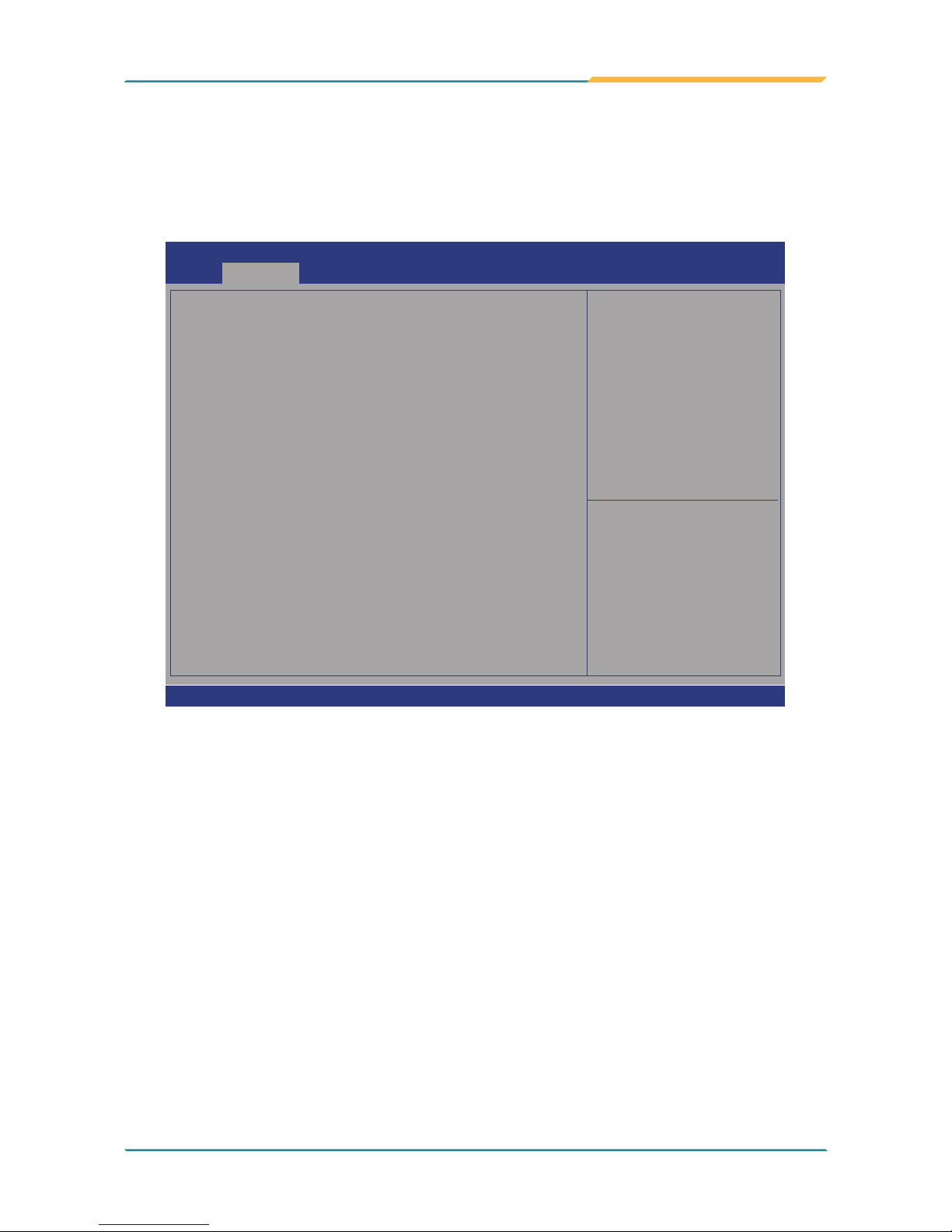
- 85 -
BIOS
5.2.6. Hardware Monitor
Select this submenu to view the main board’s hardware status. Select it to run a
report of various info as depicted below:
Aptio Setup Utility - Copyright (C) 2012 American Megatrends, Inc.
Version 2.15.1236. Copyright (C) 2012 American Megatrendes, Inc.
Pc Health Status
CPU Tempreture
System Tempreture
Vcore
+5V
5VSB
3.3V
: +52
o
C
: +52
o
C
: +0.858 V
: +4.961 V
: +4.918 V
: +3.336 V
→←: Select Screen
↓↑: Select Item
Enter: Select
+/-: Change Opt.
F1: General Help
F2: Previous Values
F9: Optimized Defaults
F10: Save and Exit
ESC: Exit
Advanced
Aptio Setup Utility - Copyright (C) 2017 American Megatrends, Inc.
Version 2.18.1263. Copyright (C) 2017 American Megatrendes, Inc.

- 86 -
BIOS
5.2.7. F81216SEC Super IO Conguration
Aptio Setup Utility - Copyright (C) 2012 American Megatrends, Inc.
Version 2.15.1226. Copyright (C) 2012 American Megatrendes, Inc.
F81216SEC Super IO Configuration
Super IO Chip F81216SEC
► Serial Port 1 Configuration
► Serial Port 2 Configuration
Set Parameters of
Serial Port 1 (COMA)
→←: Select Screen
↓↑: Select Item
Enter: Select
+/-: Change Opt.
F1: General Help
F2: Previous Values
F9: Optimized Defaults
F10: Save and Exit
ESC: Exit
Advanced
Aptio Setup Utility - Copyright (C) 2017 American Megatrends, Inc.
Version 2.18.1263. Copyright (C) 2017 American Megatrendes, Inc.
Setting
Description
Serial Port
Enable (default) or Disable Serial Port (COM).
Change Settings
Select an optimal setting for Super IO device.
► Options for Serial Port 1:
Auto;
IO=240h; IRQ=5 (default) ;
IO=240h; IRQ=3, 4, 5, 6, 7, 9, 10, 11, 12;
IO=248h; IRQ=3, 4, 5, 6, 7, 9, 10, 11, 12;
IO=250h; IRQ=3, 4, 5, 6, 7, 9, 10, 11, 12;
IO=258h; IRQ=3, 4, 5, 6, 7, 9, 10, 11, 12;
► Options for Serial Port 2:
Auto
IO=248h; IRQ=7 (default) ;
IO=240h; IRQ=3, 4, 5, 6, 7, 9, 10, 11, 12;
IO=248h; IRQ=3, 4, 5, 6, 7, 9, 10, 11, 12;
IO=250h; IRQ=3, 4, 5, 6, 7, 9, 10, 11, 12;
IO=258h; IRQ=3, 4, 5, 6, 7, 9, 10, 11, 12;
Mode Select Select RS-232 (default), RS-422 or RS-485.

- 87 -
BIOS
5.2.8. S5 RTC Wake Settings
Aptio Setup Utility - Copyright (C) 2015 American Megatrends, Inc.
Version 2.17.1246. Copyright (C) 2015 American Megatrendes, Inc.
Wake system from S5
[Disabled]
Enables or disables
system wake on alarm
event. When enabled,
system will wake on
the hr::min::sec
specified. Select
Dynamic Time, System
will wake on the
current time
+ Increase minute(s)
→←: Select Screen
↓↑: Select Item
Enter: Select
+/-: Change Opt.
F1: General Help
F2: Previous Values
F9: Optimized Defaults
F10: Save and Exit
ESC: Exit
Advanced
Setting Description
Wake System
from S5
Enable or Disable (default) system wake on alarm event.
► Options available are:
Disabled (default):
Fixed Time: System will wake on the hr::min::sec speciedc.
DynamicTime: If selected, you need to set Wake up minute increase
from 1 - 5. System will wake on the current time + increase minute(s).

- 88 -
BIOS
5.2.9. SATA Conguration
SATA Controller(s) [Enabled]
SATA Mode Selection [AHCI]
Serial ATA Port 0 mSATA-I50 (64.0GB)
Software Preserve Supported
Port 0 [Enabled]
Device Sleep [Disabled]
SATA DEVSLEP Idle Timeout Config [Disabled]
Serial ATA Port 1 Empty
Software Preserve Unknown
Port 0 [Enabled]
Device Sleep [Disabled]
SATA DEVSLEP Idle Timeout Config [Disabled]
Serial ATA Port 2 Empty
Software Preserve Unknown
Port 0 [Enabled]
Device Sleep [Disabled]
SATA DEVSLEP Idle Timeout Config [Disabled]
Enable or disable SATA Device.
Version 2.18.1263. Copyritght (C) 2017 American Megatrends, Inc.
Advanced
Aptio Setup Utility - Copyright (C) 2017 American Megatrends, Inc.
→←
: Select Screen
↓↑: Select Item
Enter: Select
+/-: Change Opt.
F1: General Help
F2: Previous Values
F9: Optimized Defaults
F10: Save & Exit
ESC: Exit
Setting Description
SATA Controller(s)
Enables (default) / disables SATA device(s).
SATA Mode Selection
Congures how SATA controller(s) operate.
► Options: AHCI (default) and RAID.
Serial ATA Port 0 ,1 ,2
SATA device information
Port 0, 1, 2
Enables (default) / disables the SATA port 0, 1, 2.
Device Sleep
Enables / disables (default) the mSATA for RTD3.
SATA DEVSLEP Idle
Timeout Cong
Enables / disables (default) SATA DTIO cong.

- 89 -
BIOS
5.2.10. CSM Conguration
Aptio Setup Utility - Copyright (C) 2016 American Megatrends, Inc.
Version 2.18.1263. Copyright (C) 2017 American Megatrendes, Inc.
Compatibility Support Module Configuration
CSM Support
CSM16 Module Version
Boot option filter
Option ROM execution
Network
Video
[Enabled]
07.79
[UEFI and Legacy]
[Do not launch]
[Legacy]
Enable/Disable CSM
Support.
→←: Select Screen
↓↑: Select Item
Enter: Select
+/-: Change Opt.
F1: General Help
F2: Previous Values
F9: Optimized Defaults
F10: Save and Exit
ESC: Exit
Advanced
Setting Description
CSM Support Enable (default) or Disable CSM Support.
Boot option lter
Control the Legacy/UEFI ROMs priority.
► Options: UEFI and Legacy (default), Legacy only, UEFI only
Network
Control the execution of UEFI and Legacy PXE OpROM
► Options: Do not launch (default) and Legacy
Video
Control the execution of UEFI and Legacy Video OpROM
► Options: UEFI and Legacy (default)

- 90 -
BIOS
5.2.11. USB Conguration
Aptio Setup Utility - Copyright (C) 2012 American Megatrends, Inc.
Version 2.15.1236. Copyright (C) 2012 American Megatrendes, Inc.
USB Configuration
USB Module Version 16
USB Devices:
1 XHCI
USB Devices:
1 Keyboard, 1 Mouse, 1 Point
Legacy USB Support
XHCI Hand-off
USB Mass Storage Driver Support
Port 60/64 Emulation
USB hardware delays and time-outs:
USB Transfer time-out
Device reset time-out
Device power-up delay
Enables Legacy USB
support. AUTO option
disables legacy
support if no USB
devices are connected.
DISABLE option will
keep USB devices
available only for EFI
applications.
→←: Select Screen
↓↑: Select Item
Enter: Select
+/-: Change Opt.
F1: General Help
F2: Previous Values
F9: Optimized Defaults
F10: Save and Exit
ESC: Exit
Advanced
[Enabled]
[Enabled]
[Enabled]
[Disabled]
[20 sec]
[20 sec]
[Auto]
Aptio Setup Utility - Copyright (C) 2017 American Megatrends, Inc.
Version 2.18.1263. Copyright (C) 2017 American Megatrendes, Inc.
Setting Description
Legacy USB Support
Enables/disables legacy USB support.
► Options available are Enabled (default), Disabled and Auto.
► Select Auto to disable legacy support if no USB device are
connected.
► Select Disabled to keep USB devices available only for EFI
applications.
XHCI Hand-off
This is a workaround for OSes without XHCI hand-off support. The
XHCI ownership change should be claimed by XHCI driver.
► The optional settings are: Enabled (default) / Disabled.
USB Mass Storage
Driver Support
Enables/disables USB Mass Storage Driver Support.
► The optional settings are: Disabled / Enabled (default).
USB hardware delay and time-out
Port 60/64 Emulation
Enables / Disables (default) I/O port 60/64h emulation support.
USB Transfer timeout
Use this item to set the time-out value for control, bulk, and interrupt
transfers.
► Options: 1 sec, 5 sec, 10 sec, 20 sec
 Loading...