

Arbonia ENY-S-460, ENY-S-270, ENY-SEL-170, ENY-SEL-36, ENY-SEL-460 Installation, Use And Maintenance Instructions
...Page 1

INSTALLATION, USE AND
MAINTENANCE INSTRUCTIONS
Appliances for residential ventilation
Via Piave, 53 • 20011 Corbetta (MI) • ITALY
Tel. +39.02.97203.1 ric. autom. • Fax +39.02.9777282 - +39.02.9772820
E-mail: info@sabiana.it • Internet: www.sabiana.it
E 11/18
D 11/18
Cod. 4051026
Page 2

Page 3

IT
UK
DE
Gentile cliente,
la ringraziamo per la ducia accordataci con l’acquisto di un nostro prodotto.
Se Lei avrà la costanza di seguire attentamente le indicazioni contenute nel presente manuale, siamo certi
che potrà apprezzare nel tempo e con soddisfazione la qualità della nostra macchina.
La preghiamo di leggere attentamente le indicazioni contenute nel manuale che riguardano l’uso corretto
del nostro prodotto, in conformità alle prescrizioni essenziali di sicurezza.
È possibile scaricare il manuale dal sito www.sabiana.it
We thank you for your custom in the purchase of this product.
By carefully following the instructions contained in this manual you will be sure to appreciate the quality
of our machine.
Please therefore carefully read the instructions of use contained in this manual, which comply with
essential safety regulations.
Sehr geehrter Kunde,
wir danken Ihnen für das uns durch den Erwerb eines unserer Produkte entgegengebrachte Vertrauen.
Wenn Sie die Ausdauer haben, aufmerksam die im vorliegenden Handbuch enthaltenen Hinweise zu
beachten, sind wir gewiß, daß Sie lange und mit Zufriedenheit die Qualität unserer Maschine schätzen
werden können. Wir bitten Sie, aufmerksam die im Handbuch enthaltenen Hinweise bezüglich der richtigen
Verwendung unseres Produktes in Übereinstimmung mit den wesentlichen Sicherheitsvorschriften zu lesen.
FR
Sie können das Handbuch von der Website www.sabiana.it herunterladen
Cher client,
Nous vous remercions de la conance que vous nous avez manifestée en achetant notre produit.
Si vous suivez attentivement les indications contenues dans le présent manuel, nous sommes certains
que vous apprécierez la qualité de notre machine.
Nous vous prions de lire attentivement les indications contenues dans le manuel sur l’utilisation correcte
de notre produit, en conformité avec les prescriptions essentielles de sécurité.
Vous pouvez télécharger le manuel sur le site Web www.sabiana.it
Page 4

Carefully read the following instruction booklet before starting up the machine.
Attention! Carefully turn o the electrical supply before removing the protections
Attention! Carefully turn o the electrical supply before removing the protections
Operations which may be carried out by the user
Interventions to be carried out exclusively by an installer or authorised technician.
Always wear work gloves.
Page 5

English
ESSENTIAL SAFETY
RULES
It is dangerous to touch the appliance with parts of
your body wet and with bare feet.
Do not perform any type of intervention or maintenance without rst having disconnected power to
the appliance.
Do not tamper with or modify the adjustment or
safety devices without being authorised and without
instructions.
Do not twist, detach or pull the power cords coming
out of the appliance even if not plugged in.
Do not pour or spray water on the appliance.
Never insert anything through the lter seat holes.
Do not remove any protection without rst having dis-
connected power to the appliance.
Do not throw or leave any residual packing material
within the reach of children as it is a potential risk of
danger.
Do not install the appliance in explosive or corrosive
atmospheres, in moist areas, outdoors or in extremely
dusty environments.
- SAFETY REQUIREMENTS
The appliance can be used by children no younger
than 8 years old and by persons with reduced physical, sensory or mental capabilities, or lack of necessary
experience and knowledge as long as they are supervised or after they have received instructions regarding
safe use of the appliance and understanding the hazards related to it.
Children must not play with the appliance.
The cleaning and maintenance to be carried out by the
user cannot be done by children without supervision.
Before performing any operation, make sure to:
1 - Disconnect electric power to the appliance.
2 - Close the water supply valve of the coil and let it
cool o (pre-and post-heating coils if installed as
accessories).
3 - Install a circuit breaker switch in an easily accessible position near the appliance or appliances.
RISK OF INJURY!
For safety purposes, during installation, maintenance
and repairs, abide by the following:
• Always wear work gloves.
• Do not be exposed to ammable gases.
RISK OF INJURY/MATERIAL DAMAGE
DAMAGE TO APPLIANCE!
The appliance is very heavy.
Lifting it can cause injuries.
Have another person help you lift it
in order to carry the machine.
Lift it slowly and pay attention that
it does not fall.
The fans can reach a speed of 3000
rpm.
Do not insert objects or your hands into the electric fan.
Do not remove the safety labels inside the appliance. If illeg-
ible, have them replaced.
Make sure to earth the appliance.
Always request original spare parts when replacing compo-
nents.
The installation site must be chosen so that there is sucient
space for the connections of the air pipes and to allow maintenance to be carried out conveniently.
Make sure there is at least 1 m of open space in front of the
appliance to allow for maintenance operations.
If the appliance is hung on a wall, make sure the wall has a
supercial mass of at least 200 kg/m2. Otherwise use a stand
to install it on the oor (optional accessory sold separately).
Do not install the appliance near bedrooms.
To improve environmental comfort, install silencers on the
ambient air input and return piping.
The appliances cannot be installed in environments cooler
than < 12°C.
The residential ventilation systems are designed for con-
stant operation to avoid the formation of condensation and
mould in the environments. The units can only be switched
o for scheduled maintenance.
The appliances cannot be used to dry structures and
masonry of new homes.
ATTENTION! It is strictly forbidden to operate the unit before
having connected the 4 air ducts to the ducting system.
/
5
Page 6

English
USE AND STORAGE
OF THE MANUAL
This instruction manual is intended for the machine
user, owner and technical installer and must always
be available for consultation.
The instruction manual indicates the intended use of
the machine, its technical features and provides indications as to its correct use, cleaning and adjustments.
It also provides important indications for maintenance,
for residual risks and anyhow to carry out operations
with particular attention.
This manual must be considered as a part of the machine and must be KEPT FOR FUTURE REFERENCE
until the nal scrapping of the machine.
The instruction manual must always be available for
consultation and preserved in a dry and protected
area.
Should it be lost or damaged, the user can request a
new manual from the manufacturer or retailer, indicating the model and serial number of the machine
shown on its rating plate.
SCOPE
BEFORE INSTALLING THE APPLIANCE
READ THIS MANUAL CAREFULLY
Residential ventilation appliances convey outdoor air
through the cross-ow heat exchanger and distribute
it to the dierent rooms by means of a duct distribution system.
Moist and stale air is suctioned and then, again
passing through the cross-ow heat exchanger, is
exhausted to the outside of the appliance by residential ventilation.
MACHINE IDENTIFICATION
There is an identication label on each appliance
bearing the data of the manufacturer and the
machine type (See Figure “A”).
Fig. “A”
This manual reects the state of technology at the
moment it was drafted. The manufacturer reserves
the right to update production and following manuals
without being obliged to update previous versions
as well.
The manufacturer will not be held liable in case of:
- improper use or misuse of the machine
- use nonconforming to that expressly specied in
this publication
- serious shortcomings in intended and recommended maintenance
- changes to the machine or any unauthorised intervention
- use of non-original spare parts or not specic for
the model
- total or partial failure to comply with the instructions
- Exceptional events
MADE IN ITALY
SABIANA S.p.A
Via Piave 53 - 20011- Corbetta (MI) - ITALY
ENERGY- S
SIZE
ENY- S - ---
TYPE
MAXIMUM
POWER INPUT
- - - W
MAXIMUN
CURRENT INPUT
- - - A
230V
50Hz
07/03
2017
021B001
WASTE DISPOSAL
Consumables and replaced parts should
be disposed of safely and in accordance
with the environmental protection legislation.
IP21
QUALITY
CONTROL
6
Page 7

RANGE
English
Model
Version
Equip-
ment
- - W
ENY-S-170
ENY-S-270
ENY-S-360
ENY-S-460
ENY-SEL-170
ENY-SEL-270
ENY-SEL-360
ENY-SEL-460
ENY-SER-170
STANDARD - -
STANDARD - -
STANDARD - -
STANDARD X -
STANDARD - X
STANDARD - X
STANDARD - X
STANDARD X X
STANDARD - X
Side
Acoustic
Insulation
Integrated
Modulating
Electric
Resistance
Flow
Conguration
Default LH
Reversible
Default LH
Reversible
Default LH
Reversible
Default LH
Reversible
LH
LH
LH
LH
RH
Integrated
Humidity
Sensor
* ** A -
* ** A -
* ** A -
* ** A -
* ** A 500
* ** A 900
* ** A 1250
* ** A 1600
* ** A 500
Integrated
Automatic
Flow Rate
Control
Energy
Class
Electric
Resistance
Power
ENY-SER-270
ENY-SER-360
ENY-SER-460
ENY-SP-180
ENY-SPM-180 ***
ENY-SP-280
ENY-SPM-280 ***
ENY-SP-370
ENY-SPM-370 ***
ENY-SP-460
ENY-SPM-460 ***
ENY-SPEL-180
ENY-SPMEL-180 ***
ENY-SPEL-280
ENY-SPMEL-280 ***
ENY-SPEL-370
ENY-SPMEL-370 ***
ENY-SPEL-460
ENY-SPMEL-460 ***
ENY-SPER-180
ENY-SPMER-180 ***
ENY-SPER-280
ENY-SPMER-280 ***
ENY-SPER-370
ENY-SPMER-370 ***
ENY-SPER-460
ENY-SPMER-460 ***
STANDARD - X
STANDARD - X
STANDARD X X
PRO X -
PRO X -
PRO X -
PRO X -
PRO X X
PRO X X
PRO X X
PRO X X
PRO X X
PRO X X
PRO X X
PRO X X
RH
RH
RH
Default LH
Reversible
Default LH
Reversible
Default LH
Reversible
Default LH
Reversible
LH
LH
LH
LH
RH
RH
RH
RH
* ** A 900
* ** A 1250
* ** A 1600
X X A+
X X A+
X X A+
X X A
X X A+
X X A+
X X A+
X X A
X X A+
X X A+
X X A+
X X A
-
-
-
-
500
900
1250
1600
500
900
1250
1600
* Humidity sensor available as an accessory
** Pressure transducer for automatic control of ow rates available as an accessory
*** Models tted with enthalpy heat exchangers
7
Page 8

English
DIMENSIONS
8
D
A
D
28
H
42
8
B
E
F
C
Model
A
(mm)
B
(mm)
Ø C
(mm)
D
(mm)
E
(mm)
F
(mm)
H
(mm)
ENY - S - 170 547 505 125 106 93.5 212.5 1041
ENY - S - 270 547 580 160 106 111 240 1041
ENY - S - 360 547 630 160 106 111 290 1041
8
Page 9

DIMENSIONS
English
A
D D
8
28
H
42
8
B
E
A
(mm)
C
B
(mm)
Ø C
(mm)
D
(mm)
E
(mm)
F
(mm)H(mm)
Model
Heat Exchangers Standard
F
Enthalpy Heat Exchangers
ENY - SP - 180 ENY - SPM - 180 600 580 125 132 111 240 1041
ENY - SP - 280 ENY - SPM - 280 600 630 160 132 111 290 1041
ENY - SP - 370 ENY - SPM - 370 660 680 160 147 126 305 980
ENY - SP - 460 ENY - SPM - 460 660 680 180 147 126 305 980
ENY - S - 460 / 660 680 180 147 126 305 980
9
Page 10

English
MACHINE DIMENSIONS WITH PACKAGING
C
B
A
Model
Heat Exchangers Standard
ENY - S - 170 / 670 1200 685 56
ENY - S - 270 / 670 1200 760 64
ENY - S - 360 / 670 1200 810 66
ENY - S - 460 / 780 1140 850 75
ENY - SP - 180 ENY - SPM - 180 720 1200 760 64 69
Enthalpy Heat Exchangers
A
(mm)
B
(mm)
C
(mm)
Heat Exchangers Standard
WEIGHT
(KG)
Enthalpy Heat Exchangers
ENY - SP - 280 ENY - SPM - 280 720 1200 810 66 71
ENY - SP - 370 ENY - SPM - 370 780 1140 850 75 80
ENY - SP - 460 ENY - SPM - 460 780 1140 850 75 80
10
Page 11

TECHNICAL DATA / ENERGY - S
Model ENY-S-170 ENY-S-270 ENY-S-360 ENY-S-460
Length mm 505 580 630 680
Width mm 547 547 547 660
Height mm 1041 1041 1041 980
Diameter of Connections - DN125 DN160 DN160 DN180
Weight kg 47 51 56 59
Maximum Flow Rate m3/h 170 270 360 460
Available Static pressure
at maximum ow rate
Flow rate of reference m3/h 120 190 250 320
Available Static pressure
at ow rate of reference
Minimum Flow Rate m3/h 60 70 90 90
Maximum Available
Static Pressure
Thermal Eciency
at ow rate of reference
EN 13141-7
Filtering Eciency
EN779 - ISO 16890
Fan Type
Maximum power output
(fans and controllers)
Maximum current output
(fans and controllers)
Electric power supply - Single phase -230 V – 50 Hz
Consumption in standby - <1W
Safety Property
Integrated modulating
electric resistance
Preheating resistance
power
Maximum current output
with resistance
Pa 100 100 100 100
Pa 50 50 50 50
Pa 250 250 350 400
% 87% 87% 90% 89%
-
-
W 45 76 125 215
A 0.6 1.1 1.5 2.0
-
-
W 500 900 1250 1600
A 3 5 7 9.2
Centrifugal with EC brushless motor - Blades back - Curves at constant
ENY-SEL-170
ENY-SER-170
F7 supply - M5 exhaust
ePM1 70% - ePM10 50%
speed
Protection: IP21
EC Compliant
ENY-SEL-270
ENY-SER-270
ENY-SEL-360
ENY-SER-360
ENY-SEL-460
ENY-SER-460
English
11
Page 12

English
TECHNICAL DATA / ENERGY - SP
Model ENY-SP-180 ENY-SP-280 ENY-SP-370 ENY-SP-460
Length mm 580 630 680 680
Width mm 600 600 660 660
Height mm 1041 1041 980 980
Diameter of Connections - DN125 DN160 DN160 DN180
Weight kg 47 51 56 59
Maximum Flow Rate m3/h 180 280 370 460
Available Static pressure
at maximum ow rate
Flow rate of reference m3/h 130 200 260 320
Available Static pressure
at ow rate of reference
Minimum Flow Rate m3/h 50 70 50 90
Maximum Available
Static Pressure
Thermal Eciency
at ow rate of reference
EN 13141-7
Filtering Eciency
EN779 - ISO 16890
Fan Type - Centrifugal with EC brushless motor - Blades back - Curves at constant
Maximum power output
(fans and controllers)
Maximum current output
(fans and controllers)
Electric power supply - Single phase -230 V – 50 Hz
Consumption in standby - <1W
Safety Property
Models with integrated
modulating resistance
Preheating resistance
power
Maximum current output
with resistance
Pa 100 100 100 100
Pa 50 50 50 50
Pa 160 240 390 400
% 91% 91% 92% 89%
- F7 supply - M5 exhaust
ePM1 70% - ePM10 50%
speed
W 50 70 120 215
A 0.6 1.0 1.0 2.0
-
ENY-SPEL-180
-
ENY-SPER-180
W 500 900 1250 1600
A 3 5 7 9.2
ENY-SPEL-280
ENY-SPER-280
Protection: IP21
EC Compliant
ENY-SPEL-370
ENY-SPER-370
ENY-SPEL-460
ENY-SPER-460
12
Page 13

TECHNICAL DATA / ENERGY - SPM (Models tted with enthalpy heat exchangers)
Model ENY-SPM-180 ENY-SPM-280 ENY-SPM-370 ENY-SPM-460
Length mm 580 630 680 680
Width mm 600 600 660 660
Height mm 1041 1041 980 980
Diameter of Connections - DN125 DN160 DN160 DN180
Weight kg 52 56 61 64
Maximum Flow Rate m3/h 180 280 370 460
English
Available Static pressure
at maximum ow rate
Flow rate of reference m3/h 130 200 260 320
Available Static pressure
at ow rate of reference
Minimum Flow Rate m3/h 50 70 50 90
Maximum Available
Static Pressure
Thermal Eciency
at ow rate of reference
EN 13141-7
Thermal hygromeric
at ow rate of reference
EN 13141-7
Filtering Eciency
EN779 - ISO 16890
Fan Type -
Maximum power output
(fans and controllers)
Maximum current output
(fans and controllers)
Electric power supply - Single phase -230 V – 50 Hz
Consumption in standby - <1W
Safety Property -
Models with integrated
modulating resistance
Preheating resistance
power
Maximum current output
with resistance
Pa 100 100 100 100
Pa 50 50 50 50
Pa 160 240 390 400
%
%
-
W 50 70 120 215
A 0.6 1.0 1.0 2.0
-
W 500 900 1250 1600
A 3 5 7 9.2
88.6% 84.8% 82.7% 81.5%
72.1% 65.6% 63.4% 58.4%
F7 supply - M5 exhaust
ePM1 70% - ePM10 50%
Centrifugal with EC brushless motor - Blades back - Curves at constant
speed
Protection: IP21
EC Compliant
ENY-SPMEL-180
ENY-SPMER-180
ENY-SPMEL-280
ENY-SPMER-280
ENY-SPMEL-370
ENY-SPMER-370
ENY-SPMEL-460
ENY-SPMER-460
13
Page 14
English
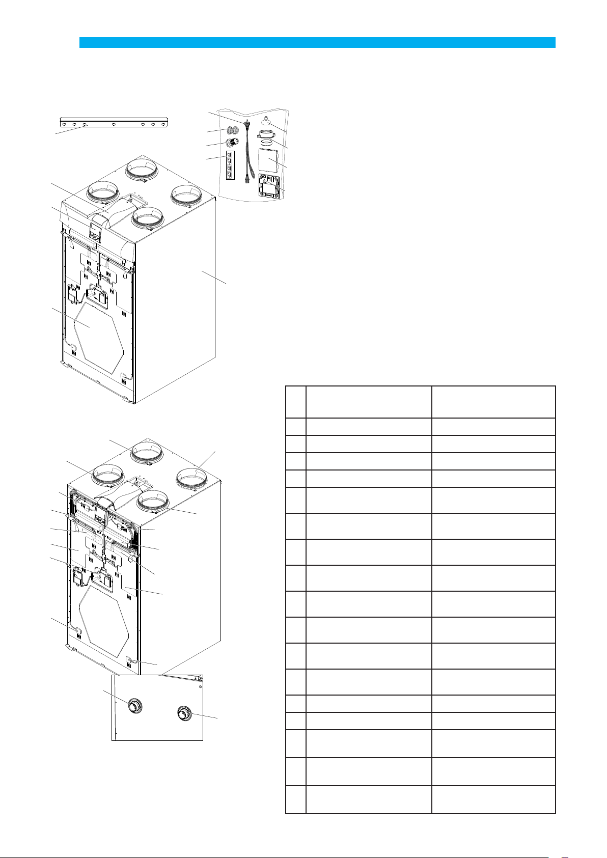
DESCRIPTION OF MACHINE COMPONENTS
6
5
2
3
7
9
10
A B C D
1 - Appliance for residential ventilation
2 - Power board
11
3 - T-EP capacitive touch controller
8
4 - Heat exchanger
12
5 - Hanging bracket
6 - Power cord
30
7 - Spacer foot
8 - Condensate drain plug
9 - Cable gland PG7
10 - Shank label (to use for right side connection)
11 - Suction cup
12 - Front cap (for remote control)
1
4
14
13
15
30 - T-EP support for wall mounting
Left side connection
(Standard Conguration)
13 Outdoor air connection
14 Exhaust air connection Supply air connection
15 Supply air connection Exhaust air connection
Right side connection
(supplementary
Extracted stale air connection
Cong.
)
17
28
19
27
23
21
25
22
29
18
24
20
16
26
16
Extracted stale air connection
17
18
Filter class F7
(outdoor air)
Filter class M5
(extracted stale air)
19 Supply air fan
20
Outdoor air temperature
21
22
temperature probe (T3)
Exhaust air temperature
23
Supply air temperature
24
Stale air
exhaust fan
probe (T1)
Extracted stale air
probe
probe (T2)
Outdoor air connection
Filter class M5
(extracted stale air)
Filter class F7
(outdoor air)
Stale air
exhaust fan
Supply air fan
Extracted stale air
temperature probe (T3)
Outdoor air temperature
probe (T1)
(T4)Supply air temperature
probe (T2)
Exhaust air temperature
probe
25 Condensate drain ------
26 ------ Condensate drain
27
LH Integrated Resistance
28
29
Bypass
Damper System
(if any)
------
RH Integrated Resistance
Bypass
Damper System
------
(if any)
14
Page 15

English
OK
INSTALLATION (OPERATION
CARRIED OUT EXCLUSIVELY BY
QUALIFIED PERSONNEL)
Attention! Installation of the appliance for residential ventilation must only be carried out by
qualied personnel to avoid damage or injury.
Attention! To protect the system against
lth and humidity, all the openings must
remain closed until commissioning, for
example using protective covers.
INSTALLATION INSTRUCTIONS
• The residential ventilation appliance can be
installed in dry environments with the temperature
above 12°C, for example in a utility room.
Installation temperature: from +12 °C to +40 °C.
• Relative humidity (installation environment): max.
60%.
• Storage temperature: -20 ° C to +60 ° C.
PLEASE NOTE: if the temperature in the installation room
drops below 12°C, there could occasionally be condensate
on the external covering of the appliance.
• Position the appliance so that the section up to the
external outlet of the outdoor air and exhaust air
inlet ducts is as short as possible.
• The vibrations produced by the residential ventilation appliance must be dampened. The installed
appliance must be soundproofed.
• The residential ventilation appliance is mounted
with a wall bracket (supplied with the machine).
• The appliance can be mounted on the oor using
optional stands.
• The appliance must be accessible to perform
maintenance and repairs.
• Air flow rates must be set correctly in compliance with standard DIN 1946, part 6.
• The appliance can be commissioned after having
completed installation of the entire residential
ventilation system.
- Fastening the bracket to the wall
Take the bracket and apply it to the wall, making sure that it is
attached in a horizontal position using a spirit level, as described
in the gure below (Fig. 1).
PLEASE NOTE: the screws are not included in the supply.
Choose the screws and relative plugs based on the type
of wall.
WALL INSTALLATION OF APPLIANCE
(Fig. 1)
A
R5
B
5
20
50 50
242,5
485
525
B
50 50
C
H MIN
262,5
MIN 200
1 - Position the bracket and drill the necessary holes
(Fig.1). Make sure the appliance is horizontal.
2 - Secure the bracket by applying the screws.
Model
ENY-S-170
ENY-SEL-170
ENY-SER-170
ENY-S-270
ENY-SEL-270
ENY-SER-270
ENY-S-360
ENY-SEL-360
ENY-SER-360
ENY-S-460
ENY-SEL-460
ENY-SER-460
ENY-SP-180*
ENY-SPEL-180
ENY-SPER-180
ENY-SP-280*
ENY-SPEL-280
ENY-SPER-280
ENY-SP-370*
ENY-SPEL-370
ENY-SPER-370
ENY-SP-460*
ENY-SPEL-460
ENY-SPER-460
* Dimensions are also valid for enthalpy models
H MIN
(mm)A (mm)B (mm)C (mm)
1190 600 11 1000
1190 600 11 1000
1190 600 11 1000
1130 660 67.5 940
1190 600 37.5 1000
1190 600 37.5 1000
1130 660 67.5 940
1130 660 67.5 940
15
Page 16

English
- Positioning the appliance (Fig.2)
1 - Position the appliance by hooking it to the hanging
bracket (1).
2 - Position the supplied spacer foot (2) to guarantee
that the appliance is level.
3 - Secure the appliance to the wall (3).
4 - Mount the condensate drain at the bottom of the
appliance.
PLEASE NOTE: the screws are not included in the supply.
Choose the screws and relative plugs based on the type
of wall.
1
(Fig. 2)
8
1
2
16
2
3
3
Page 17

English
1
2
3
4
5
13
M8 x 20
- Condensate drain connection
The connection for the condensate drain is located
underneath the appliance:
Connect the condensate drain to the domestic sewage
system using a duct or pipe (siphoned).
Condensate must be drained from a minimum height
of 100 mm.
PLEASE NOTE: if you choose the version with right
side connection, invert the condensate drain plug (see
paragraph “
How to change connection”).
FLOOR INSTALLATION OF APPLIANCE
- OPTIONAL ACCESSORY-
As an alternative, the residential ventilation appliance
can be installed using the oor stands.
- Fixing the stands
4
1
5
3
2
13
M8 x 20
1 1/2 " G
min 100
Attention! Make sure that the siphon of the
condensate drain connected to the
domestic sewer system is always full of water.
Y
1 - Fix the stands(1) using the screws (2) and washers
(3),supplied with the accessory, at the bottom of the
appliance (4). Fasten the crossbar (5) to the support (1).
2 - Lift the unit and position it vertically
3 - Use a spirit level to check the position of the appliance.
Attention! Make sure that the end of the
siphon is at least 100 mm below the water
level.
200 ÷ 225
17
Page 18

English
230 V 50 HZ
ELECTRICAL CONNECTIONS
General requirements
• Before installing the appliance, make sure that the
rated supply voltage is 230V - 50 Hz.
• Make sure that the electric system is suitable to
supply, in addition to the operating current required
by the unit, the current necessary to supply the
household appliances and equipment already in use.
• Perform the electrical connections according to
national laws and standards in force.
• Install an omnipolar switch upstream of the unit
with a minimum contact distance of 3.5 mm.
• The unit must always be earthed.
• Check the power cord is in perfect condition. In no
case must you repair a damaged cord with insulation
tape or clamps.
If the power cord is damaged, it must be replaced by
the Technical Assistance Service or anyhow by an individual with a similar qualication to prevent any risk.
• The appliances
the display controller on board the unit.
for residential ventilation
are built with
• When the appliance is connected electrically the
controller is also powered.
- Take the power cord from the accessory bag.
- Couple the cord to the machine.
- Plug in the power cord.
230 V 50 HZ
POWER BOARD
FAN2
FAN1
N1 - L1
F
DIP1
DIP2
BP
KNX
DL2
F1
DL2
MC4
CONTROL
N1
M23
230VAC
L1
FAN1
N
T.Type
F3
M16
FAN2
L L
N
M24
2223
2021
1918
EH2
EH2
EH4 EH3
F2
F1
109876543
6543
KD1
KD2
ON
ON
RS485
321
21
ON
21
ON
BP
KNX
RH-CO2
97
864
5
M12
EH1
F2
FCFC
MC1
FC-FC
C3-C3C2-C2C1-C1
EH1
FC-FC
C3-C3
C2-C2
MC2
C1C1C2C2C3C3
C1-C1
IAQ
IAQ
DL1
DL3
TTL
DL1
DL3
T2T3T4 T1
TTL
BD
18
CONTROL
RS485
RH-CO2
D+
D-
0
T4
T3
T2
T1
BD
Page 19

KEY:
Item Description Notes
English
N1-L1
F
FAN 1
FAN 2
F1
F2
T1 ÷ T4
CONTROL
C1-C1
C2-C2
C3-C3
FC-FC
IAQ
RS485
DIP 1
DIP 2
MC4
BP
BD
TTL
EH1
EH2
DL2
DL3
230 Volt power terminals /
Fuse 5x20 /
230 Volt Power Supply - Fan 1 /
230 Volt Power Supply - Fan 2 /
0-10 Volt Signal - Fan 1 Fan 2 with inverse conguration
0-10 Volt Signal - Fan 2 Fan 1 with inverse conguration
Temperature sensors /
Control Panel T-EP controller supplied with unit
NO potential.free contact (input)
NO potential-free contact (input) Booster function active when the contact is closed
NC potential-free contact (input) (active only if
JUMPER MC1 open)
SPST Potential-Free Contact /
Internal Relative Humidity Sensor /
Modbus Connection /
Conguration Dip Switch See Conguration Dip Switch table
Address Dip Switch for ModBus networks 8 Dip Switches - for max 60 units
Master/slave jumper or Modbus network
Dierential Pressure Sensor Connection for automatic air ow rate control
By-pass damper connection (FreeCooling) /
Connection for additional boards Accessory/Optional
PWM control preheating output /
Pre-Treatment output for controlling 230 Volt ON/
OFF actuators or enabling external modulating
resistance
Power on LED /
Status and alarm LED See alarm table
Remote On/O function – unit O when the contact is
closed
See Fireplace and Boiler functions
The network must be closed on the last unit in case of
RS485 Modbus connection. It is closed by closing Jumper
MC4.
Accessory for ENY-S models
Standard for ENY-SP models
Antifreeze with external systems
19
Page 20

English
CONFIGURATION DIP SWITCH (DIP 1)
DIP NO.
1 OFF
2 OFF
3 OFF
4 OFF
5 OFF
6 OFF
7 OFF
8 OFF
9 OFF
DEFAULT
OFF
LH Fan Cong
(STANDARD CONFIGURATION)
No Pre-Treatment Air Pre-Treatment Air Present
If DIP2 ON
Modulating electric resistance
N/A N/A
N/A N/A
FC-FC transmits error signal
to remote control unit
No Geothermal Hydronic Coil
Contact C3-C3 with function that
prevents
negative ambient pressure in
presence of chimney
If DIP2 ON
Internal modulating
preheating resistance
ON
RH Fan Cong
Right side connection
If DIP2 ON and DIP7 OFF
Electric Resistance ON/OFF
Hot water coil with ON/OFF valve
If DIP2 and DIP3 ON
Geothermal Hydronic Coil Present
Contact C3-C3
with atmospheric boiler start-up booster
If DIP2 ON, DIP3 OFF
External modulating preheating resistance
(supplementary
N/A
Cong.
)
10
OFF
N/A N/A
20
Page 21

English
1
1a
CONTROL
PG7
Connection with remote control
The control is provided by default tted on the appliance, however it can also be remoted by tting it on
the wall.
Always disconnect power
before accessing the unit.
1- Remove the controller from the front panel using
the suction cup accessory.
2- Remove the 3-pole connector coupled to the controller.
3) Unscrew the top cover to access the electric compartment where the power board is located.
3
4) Remove the cable connected to the “
connector (terminals 1-2-3) of the power board.
4
CONTROL
1 2 3
CONTROL
”
2
5) Perform the new connection to position the controller on the wall, respecting the sequence of the
terminal numbers:
a) apply the supplied cable gland as indicated in the
gure;
b) x the cable in the cable gland;
c) connect the cable to terminals1-2-3 from the power
board to the controller respecting the numbers;
21
Page 22

English
Installing controller on the wall
10
9
57
1
3 4
2
8
9
10
60
1
56
2
3
4
22
Page 23

English
T-EP TOUCH CONTROLLER
Introduction
This device was designed for the control of controlled
mechanical ventilation units. It is suitable for ENERGY
SMART units.
The Main Screen on the control panel permits access
to two settings sub-menus:
1. USER Settings Menu where the user can select the
operating mode and set the clock;
2. TECHNICAL Settings Menu where the installer can
calibrate the ow rate, change the standard unit operating parameters and monitor the operating state.
On the main screen, the user can view alarm reports
and main readings of the temperature and humidity.
The USER Settings Menu oers these options:
The MAIN SCREEN features the following options:
1. The preheating icon indicates activation of Antifreeze mode.
2. A timed warning icon blinks to suggest replacing
the lters.
3. A damper bypass icon indicates automatic activation of free-cooling mode.
4. Weekly Program Display 4.
Indoor Air
Temperature
1. Manual selection of the following preset ventilation
modes:
a) Party Mode - Intensive timed ventilation
b) Holiday Mode - Permanent Anti-mould ventilation
2. Automatic Mode, available for units equipped
with air quality sensor (humidity or CO2).
3. Customised selection of desired air ow rate in
manual mode:
a) 100% - Nominal ventilation (standard)
b) 70% - Reduced ventilation (nighttime)
c) 45% - Humidity Control for High Humidity Rate
Environments
d) 25% - Humidity Control for Low Humidity Rate
Environments
4. Weekly Programming.
°C
DAY
The TECHNICAL Menu oers these options:
1. Option of conrming or editing the operating parameters.
2. Monitoring of work conditions.
3. Setting the nominal calibration speed of the fans.
4. Input and Selection of the Weekly Program available
to the user.
4
The four Weekly Programs can be set by the installer and
another 4 weekly programs can be set up according to the
user’s specic requirements.
The User Settings menu allows the user to enable or disable
the Weekly Program congured by the installer.
23
Page 24

English
V
DAY
P
AUTO
°C
°F
T2T1
T4
T3
A
B
C
D
2/2a
1
14
6
7/7a
9
8
4
5
3
15
12
13
11
10
17
16
AUTO
P
P
DAY
Description of the Controller
Keys:
A
B
C
D
_
Display - Functions
1
2
3
4
5
6
7
24
• Start and Stop the machine;
• Access Technical Menu (only authorised sta ): when
the unit is ON, press the keys and at the same
time for 5 seconds to access the menu.
• Access User Menu;
• Access Technical Menu (only authorised sta ): when
the unit is ON, press the keys and at the same
time for 5 seconds to access the menu;
• Exit Menu.
• Conrm.
• Move a nger on the TOUCH PAD to:
+
• Increase/decrease the ventilation speed; or the
setting parameters;
• Scroll between functions.
• Manual Ventilation function.
• Booster function
• Automatic mode.
• Preset ventilation:
Party mode
• Preset ventilation:
Holiday mode
• Time setting
• Current day setting
• Weekly program activation
• Weekly program deactivation
Display - Alerts and alarms
• Display of current time
2a
• Text eld
• Number of current program
7a
• Presence of Person
8
9
• Current day
• Alarm alert
10
• Value alert (Temperature, voltage)
11
°C
• Filter Maintenance/Dirty lter
12
• Bypass in use - Free-cooling mode
13
• Preheating - Antifreeze mode icon
14
15
16
17
• Function lock activated
• User Menu active
• Installer settings menu active
Page 25

1
2
3
5
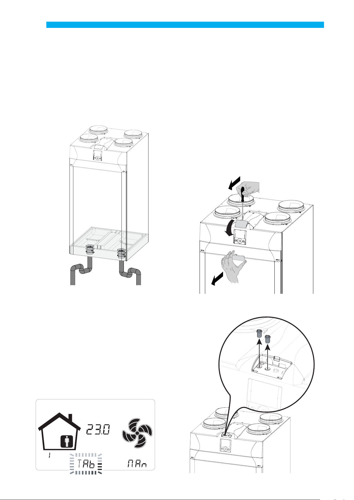
COMMISSIONING
The connections can be swapped to allow for exible
installation of the appliances for residential ventilation.
The dierence in the connections regards the position
of the air connections, of the lters and of the condensate drain and RH sensor.
English
How to change connection
(For Appliances not equipped with internal modulating electric resistance)
The default appliance is set in the version with left
side connections.
To change the machine to the RIGHT side version,
proceed as follows:
Left side connection (Standard version)
C
A
A - Outdoor air
B - Supply air
C - Exhaust air
D - Extracted stale air
B
D
Always disconnect power
before accessing the unit.
1. Unscrew the top cover.
2. Remove the top cover.
Right side connection (supplementary version)
B
D
A - Outdoor air
B - Supply air
C - Exhaust air
D - Extracted stale air
PLEASE NOTE: Apply the labels, supplied with the
unit, based on the new conguration
C
A
3. Position the DIP n°1 of the power board based on
the desired connection:
DIP 1 = OFF LH installation (default)
DIP 1 = ON RH installation
DIP 1
1
ON
25
Page 26

English
4. Position the lters as in the gure based on the
desired connection:
a - Open the front panel
1
The operations related to the connection
must only be carried out by qualied
personnel to avoid damage or injury.
The units equipped with integrated
electric resistance cannot undergo ow
conguration inversion. The machine
must be purchased with resistance in the left or
right side version depending on the envisaged
installation requirements
b - remove the plugs from the lters
3
2
Standard Conguration
F7
Right Side Conguration
M5
c - extract the lters and insert them based on the
chosen connection.
26
M5
F7
Page 27

Moving the Humidity sensor
for Unit ENY-SP
The sensor is placed by default in the version with left
side connections (standard see picture 5).
To position the sensor for the Right side connection
(supplementary version) you must:
1
English
4
2
3
5
Position of the sensor
STANDARD version
6
Position of the sensor
RIGHT side version (supplementary)
Put all the components back in place and proceed with
the assembly of the condensate drain
In the event of installing the sensor as an accessory,
follow the instructions of the information sheet attached to the accessory pack.
27
Page 28
English
1
Condensate drain connection
Position the condensate drain based on the desired
connection:
Unscrew the plug and fix a drain or siphon as
indicated in the gure.
Condensate must be drained from a minimum
height of 100 mm.
If you choose the version with right side connection,
swap the plug of the condensate drain.
To set the air ow rate based on the number of fan
revolutions, there are two possible types of calibration:
• STANDARD CALIBRATION
• AUTOMATIC CALIBRATION
only with Automatic Flow Rate Control system installed
STANDARD CALIBRATION
– Left Side Configuration –
1. Use a screwdriver to remove the front panel cover.
standard
connection
Y
Y
right
side connection
SETTING THE FLOW RATES
Before setting owrates, fans are run at factory default
speed.
Before setting owrates, Touch Pad is inithbited to
perform any speed modulation. This is communicated
by the message "Tab " blinking in the central eld of
the display.
WARNING!: no speed regulation is possible without
rst owrate setting
2
3
2. Remove the rubber caps of the connections P1 and P2
relative to fan V1.
P
1
P
2
P
3
P
4
28
°C
DAY
Page 29

English
V
V
V
_
V
3. Connect the dierential pressure gauge.
P
1
P
2
P
3
P
4
6. Use the TOUCH PAD to select the installer menu
.
Press the Enter key to conrm .
Select the “V” symbol and conrm .
The message V1 ashes;
Perform the setting of the fan V1;
access the menu by pressing enter, the display shows:
set the nominal design
flow rate (m3/h) using
the TOUCH PAD
V
+
.
_
Press the Enter key to conrm .
Change the voltage value relative to the fan speed
using the TOUCH PAD
+
until the dierential pressure gauge displays a value equal to the value of the
objective pressure drop (Pascal) shown on the display.
4. Turn on the appliance at the ON/OFF key on the
display.
5. Press the ON/OFF and “M” Menu keys at the same
time to access the TECHNICAL MENU.
V1 fan
speed voltage
80 = 8.0 Volt
V
fan rpm
Objective
pressure drop
=
Press the Enter key to conrm .
Before going on to set the fan V2, you must disconnect
the dierential pressure gauge from connections P1
and P2 and put the rubber caps back in place.
29
Page 30

English
1
Now proceed with connection of the dierential
pressure switch to connections P3 and P4
P
1
P
6
2
P
3
P
4
– right Side Configuration –
1. Use a screwdriver to remove the front panel cover.
2
3
“ V1 ” currently ashes on the control display;
use the TOUCH PAD
conrm by pressing enter.
Carry out the procedure described above for V1
also for fan V2.
When fan V2 has been set as well, go back to the
main screen by pressing “M” 3 times.
Disconnect the dierential pressure gauge and put
the rubber caps and the cover of the front panel
back in place.
+
to select fan “ V2 ” and
_
2. Connect the dierential pressure gauge to connections P3 and P4.
P
1
P
6
2
P
3
P
4
30
Page 31

English
V
V
V
_
V
3. Turn on the appliance at the ON/OFF key on the
display.
4. Press the ON/OFF and “M” Menu keys at the same
time to access the TECHNICAL MENU.
5. Use the TOUCH PAD to select the installer menu
.
Press the Enter key to conrm .
Select the “V” symbol and conrm .
The message V1 ashes;
Perform the setting of the fan V1;
access the menu by pressing enter, the display
shows:
set the nominal design ow rate (m3/h)
using the TOUCH
PAD
V
+
.
_
Press the Enter key to conrm .
Change the voltage value relative to the fan speed
+
using the TOUCH PAD
until the dierential
pressure gauge displays a value equal to the value
of the objective pressure drop (Pascal) shown on
the display.
V1 fan
speed voltage
80 = 8.0 Volt
V
fan rpm
Objective
pressure drop
=
Press the Enter key to conrm .
Before going on to set the fan V2, you must disconnect the differential pressure gauge from
connections P3 and P4 and put the rubber caps
back in place.
31
Page 32

English
V
V
V
Now proceed with connection of the dierential
pressure switch to connections P1 and P2
P
1
P
2
P
3
P
4
AUTOMATIC CALIBRATION
onLy with automatiC fLow rate ControL
SyStem inStaLLed
1. Turn on the appliance
by pressing the ON/OFF key on the display.
2. Press the ON/OFF and “M” Menu keys at the same
time to access the TECHNICAL MENU.
“ V1 ” currently ashes on the control display;
use the TOUCH PAD
+
to select fan “ V2 ” and
_
conrm by pressing enter.
Carry out the procedure described above for V1
also for fan V2.
When fan V2 has been set as well, go back to the
main screen by pressing “M” 3 times.
Disconnect the dierential pressure gauge and put
the rubber caps and the cover of the front panel
back in place.
3. Use the TOUCH PAD to select the installer menu
.
Press the Enter key to conrm .
Select the “V” symbol and conrm .
The message V1 ashes;
Perform the setting of the fan V1;
access the menu by pressing enter, the display shows:
set the nominal design
ow rate (m3/h) using
the TOUCH PAD
V
+
.
_
Press the Enter key to conrm .
32
Page 33

English
V
V
V
4. The display will show:
Voltage value
V1fan speed
Air ow m3/h
V
Air ow rate
measured by
the pressure
transducer
target
Air ow rate
Wait for the automatic calibration system to align the
value measured by the transducer to the target value.
Voltage value
V1 fan speed
V
Air ow rate
measured by
the pressure
transducer
=
target
Air ow rate
5. Once fan V1 is calibrated, the system automatically
starts calibrating fan V2.
The display with show:
Voltage value
V2 fan speed
WARNING:!: In case where one fan cannot be run at the
target ow rate, message "Out of Range" is temporarily
displayed.
Then, system steps to next extraction fan balancing or
ends the ow rates setting procedure.
When "Out of Range" is displayed, last ow rate blown
by fan just before the message is the one set by the system, which is the ow rate as close as possible to target.
Setting the clock and day of the week
1. Turn on the appliance at the ON/OFF key on the
display.
2. Press the ON/OFF and “M” Menu keys at the same
time to access the TECHNICAL MENU.
Air ow m3/h
V
Air ow rate
measured by
the pressure
transducer
target
Air ow rate
Wait for the automatic calibration system to align the
value measured by the transducer to the target value.
Once fan V2 is calibrated,
the system automatically goes back to the main
screen of the technical menu (symbol “V” ashes).
NOTE: with pressure transducer mounted, the MENU
“PAr” will show a parameter called “Sprc”; this parameter is the imbalance of the return ow rate compared
to the supply ow rate.
It can be altered with a range from +20 to -20 (%).
Example: if the parameter set is +10, the return is 10%
less than the supply ow rate.
3. Use the TOUCH PAD to select the “clock” icon;
“ ” starts to blink.
Press “enter” to conrm .
Use the TOUCH PAD to set the current hour.
Press “enter” to conrm.
Use the TOUCH PAD to set the current minutes.
33
Page 34

English
+
-
P
P
M
x3
Press “enter” to conrm.
Use the TOUCH PAD to set the current day.
Press “enter” to conrm.
P
V
+
-
DAY
Setting of the weekly program
There is a choice of 8 weekly programs: 4 preset
programs and 4 free programs that can be modied
at will.
Selection of the preset weekly program:
Programs P1-P2-P3-P4
1. Turn on the appliance at the ON/OFF key.
2. Press the ON/OFF and “M” Menu keys at the
same time.
+
-
DAY
3. Use the TOUCH PAD to select the installer
menu .
Press the Enter key to conrm .
4. Select the “P” symbol and conrm .
Now choose the program to be set from P1 - P2 -
P3 and P4 (see the schedules on the next page).
+
-
DAY
Use the TOUCH PAD to increase or de-
+
crease the value.
_
Use the Conrm button to conrm and
move to the next setting.
Set the day of the week as follows:
day 1 = Monday / day 2 = Tuesday
day 3 = Wednesday ... ... day 7 = Sunday
5. Press “M” three times to return to the main
screen.
34
Page 35

DAY
HOUR
SPEED
45%
70%
100%
0 – 1 1 – 2 2 – 3 3 – 4 4 – 5 5 – 6 6 – 7 7 – 8 8 – 9 9 – 10 10 – 11 11 – 12 12 – 13 13 – 14 14 – 15 15 – 16 16 – 17 17 – 18 18 – 19 19 – 20 20 - 21 21 - 22 22 - 23 23 - 24
45%
70%
100%
Monday - Friday
Saturday - Sunday
Tables of settings for the preset weekly program
45%
70%
100%
Monday - Sunday
45%
70%
100%
45%
70%
100%
Monday - Friday
Saturday - Sunday
45%
70%
100%
Monday - Friday
P1
- Weekly program, family with children, both
parents work away from home during the day.
0 – 1 1 – 2 2 – 3 3 – 4 4 – 5 5 – 6 6 – 7 7 – 8 8 – 9 9 – 10 10 – 11 11 – 12 12 – 13 13 – 14 14 – 15 15 – 16 16 – 17 17 – 18 18 – 19 19 – 20 20 - 21 21 - 22 22 - 23 23 - 24
DAY
HOUR
SPEED
P2 - Weekly program, family with steady presence
at home during the day.
DAY
DAY
HOUR
HOUR
SPEED
SPEED
0 – 1 1 – 2 2 – 3 3 – 4 4 – 5 5 – 6 6 – 7 7 – 8 8 – 9 9 – 10 10 – 11 11 – 12 12 – 13 13 – 14 14 – 15 15 – 16 16 – 17 17 – 18 18 – 19 19 – 20 20 - 21 21 - 22 22 - 23 23 - 24
English
P3 - Weekly program, working family who comes
home for lunch.
DAY
HOUR
SPEED
HOUR
SPEED
0 – 1 1 – 2 2 – 3 3 – 4 4 – 5 5 – 6 6 – 7 7 – 8 8 – 9 9 – 10 10 – 11 12 – 13 13 – 14 14 – 15 15 – 16 16 – 17 17 – 18 18 – 19 19 – 20 20 - 21 21 - 22 22 - 24
DAY
0 – 1 1 – 2 2 – 3 3 – 4 4 – 5 5 – 6 6 – 7 7 – 8 8 – 9 9 – 10 10 – 11 11 – 12 12 – 13 13 – 14 14 – 15 15 – 16 16 – 17 17 – 18 18 – 19 19 – 20 20 - 21 21 - 22 22 - 23 23 - 24
P4 - Weekly program, oce used from Monday to
Friday.
DAY
HOUR
SPEED
0 – 1 1 – 2 2 – 3 3 – 4 4 – 5 5 – 6 6 – 7 7 – 8 8 – 9 9 – 10 10 – 11 11 – 12 12 – 13 13 – 14 14 – 15 15 – 16 16 – 17 17 – 18 18 – 19 19 – 20 20 - 21 21 - 22 22 - 23 23 - 24
11 – 12
35
Page 36

English
-
P
Creation of the free weekly program: Programs
P5-P6-P7-P8.
It is possible to create 4 weekly programs at will,
according to your habits and needs.
Proceed as follows:
1. Turn on the appliance at the ON/OFF key.
2. Press the ON/OFF and “M” Menu keys at the same
time.
3. Use the TOUCH PAD to select the installer menu
.
Press enter to conrm .
4. Select the “ P ” symbol and conrm
Now select the rst free program to be created from
among P5 - P6 - P7 or P8.
5. Once the program number is dened, following
scheduling should be done:
- dene the day
- dene fan speed at the rst time step, which starts
by default at 00:00.
Use the TOUCH PAD with the purpose to set 4 avail-
able speeds plus Party Mode speed.
Blades are displayed into fan icon accordingly.
P
+
-
+
DAY
P
DAY
P
-
+
-
- dene hour of rst time step end
- repeat procedure for next time step
- maximum number of time steps is 8
6. After programming the rst day, press “M” to
move to the next day; it is possible to extend the
program created for the rst day to the other days
of the week (Xtend= extend):
DAY
P
+
If you select “YES”the program is automatically copied
to the other days of the week; if instead you select
“no“, you can then use the TOUCH PAD to select a
day and repeat the programming process.
+
DAY
P
DAY
P
DAY
P
-
+
-
+
-
+
PLEASE NOTE: the daily hourly program is set by
default at OFF.
DAY
P
-
36
Page 37

Low
Nominal
Low
Nominal
Monday - Friday
Saturday - Sunday
Low
Nominal
Low
Nominal
Monday - Friday
Saturday - Sunday
P .............................
DAY
HOUR
0 – 1 1 – 2 2 – 3 3 – 4 4 – 5 5 – 6 6 – 7 7 – 8 8 – 9 9 – 10 10 – 11 11 – 12 12 – 13 13 – 14 14 – 15 15 – 16 16 – 17 17 – 18 18 – 19 19 – 20 20 - 21 21 - 22 22 - 23 23 - 24
SPEED
DAY
HOUR
0 – 1 1 – 2 2 – 3 3 – 4 4 – 5 5 – 6 6 – 7 7 – 8 8 – 9 9 – 10 10 – 11 11 – 12 12 – 13 13 – 14 14 – 15 15 – 16 16 – 17 17 – 18 18 – 19 19 – 20 20 - 21 21 - 22 22 - 2 3 23 - 24
SPEED
P .............................
DAY
HOUR
SPEED
0 – 1 1 – 2 2 – 3 3 – 4 4 – 5 5 – 6 6 – 7 7 – 8 8 – 9 9 – 10 10 – 11 11 – 12 12 – 13 13 – 14 14 – 15 15 – 16 16 – 17 17 – 18 18 – 19 19 – 20 20 - 21 21 - 22 22 - 23 23 - 24
English
DAY
HOUR
0 – 1 1 – 2 2 – 3 3 – 4 4 – 5 5 – 6 6 – 7 7 – 8 8 – 9 9 – 10 10 – 11 11 – 12 12 – 13 13 – 14 14 – 15 15 – 16 16 – 17 17 – 18 18 – 19 19 – 20 20 - 21 21 - 22 22 - 2 3 23 - 24
SPEED
IMPORTANT! complete the table(s) with the conguration of the program created.
37
Page 38

English
P
AUTO
P
AUTOPAUTO
AUTO
P
AUTO
P
OPERATIONAL
PROCEDURES USER
START AND STOP
THE HEAT RECOVERY UNIT
To turn the unit on, press the ON/OFF power key as
shown in the gure to the right (Fig. 1).
If this icon is
present, the unit
DAY
SELECTING THE OPERATING MODE
ON THE T-EP CONTROLLER
Press “M” to access the User Settings Menu (Fig. 2).
The following options are available:
is o.
(Fig. 1)
• MANUAL VENTILATION FUNCTION;
• PRESET VENTILATION FUNCTIONS:
- PARTY;
- HOLIDAY;
AUTO
•
AUTOMATIC MODE, available for units
equipped with air quality sensor (humidity or CO2)
• WEEKLY PROGRAM ACTIVATION;
• CURRENT DAY AND TIME SETTING.
(Fig. 2)
AUTO
P
Press “M” to
access the menu.
Use the TOUCH PAD to pass from one function
to another.
To access the desired function, please press the con-
rmation button .
38
Page 39

English
• MANUAL VENTILATION FUNCTION
;
Press "M” and scroll with the TOUCH PAD until the
“Manual ventilation" mode starts ashing.
Then press “Conrm” .
°C
DAY
If this icon is
present, the
operating mode
is MANUAL
With the "Manual ventilation” mode enabled,
the speed of the fan at the various points can
be adjusted by scrolling with the TOUCH PAD.
Rotating the key clockwise on the pad
increases the speed of the fan while
anticlockwise decreases the speed of the fan.
• AUTOMATIC MODE;
Available for units equipped with air quality sensor
(humidity or CO2).
Press "M” and scroll with the TOUCH PAD until the
AUTOMATIC mode starts ashing.
Then press “Conrm” .
If this icon is
present, the
operating mode
is AUTOMATIC
AUTO
°C
DAY
The advanced centralised control systems are
equipped with an RH% humidity sensor or else an
external CO2 sensor.
“Manual ventilation” mode at 100% is the standard
operating mode, corresponding to the nominal air
ow rates set by the installer upon initial conguration.
Speed
No.
4a
_
+
3a
2a
1a
Modulation
(default values)
100%
70%
45%
25%
When” Automatic Mode” is enabled, fan speed is
controlled by an automatic control cycle relative to
internal instantaneous humidity and CO2 variations.
• AUTOMATIC MODE
WITH HUMIDITY SENSOR
The fan speed is set according to the interval relating to
the ambient relative humidity detected by the sensor.
If the ambient humidity is compatible with the
ambient comfort (typically between 25% and 50%),
then a special control for air exchange is not necessary
and the user can control the speed of the fans as in
Manual Mode.
If the ambient humidity temporarily goes beyond the
ambient comfort range, then an automatic variable
ow control mode is engaged, for tracking an ambient
humidity target value.
The target value is continuously calculated by the
system as a daily average of the ambient humidity.
This way the system reacts automatically to restore as
much as possible the comfort conditions lost due to an
extraordinary event, such as steam production caused
by a hot shower or a pot while cooking.
In automatic variable ow control mode, the user can
manually change
the speed of the fans as required at
any time. The automatic mode will be restored at the
next signicant ambient humidity variation.
39
Page 40

English
2000
PPM CO
2
P
AUTO
P
AUTO
If, however, the poor comfort conditions persist, then
it will mean that the low or high humidity is not due
to extraordinary and temporary events, but depends
on harsh weather conditions, such as winter frost or
extreme heat.
In these extreme conditions, the automatic mode sets
the fan at minimum speed, in order to isolate as much
as possible the internal environment from the external
one and at the same time preserve the ambient comfort.
Low humidity emergency speed can be modied by installer by the mean of "ErHs", included into "Par" menu.
Wet climate ventilation mode is eective in case a cooling system with dehumidication is in place. In thic case
it is advisable to eneable the function by operating on
variable HrHis.
• AUTOMATIC MODE WITH
CO2 SENSOR
The variable ow rate control based on the CO2
detected acts according to xed parameters, though
they can be modied by the installer, according to
the following diagram:
FLOW MANAGEMENT LOGIC CHART
Nominal
Velocità nominale
speed
IN RELATION TO PPM CO
2
Incremento
Proportional
proporzionale
increase
“PART Y” mode is a timed function (default 3 hours).
The speed percentage of the “PART Y” mode is set
as a parameter by the installer according to the
customisations requested by the user, starting from
the standard value of 130% compared to the nominal
speed.
• HOLIDAY MODE
Press “M” and scroll with the TOUCH PAD until the
“HOLIDAY” mode starts ashing.
Then press “Conrm” .
+
-
°C
Minimum
speed
Velocità minima
0 200 400 600 800 1000 1200 1400 1600 1800
CO2LO
CO2std CO2HI
• PARTY MODE
Press “M” and scroll with the TOUCH PAD until “PART Y”
mode starts ashing.
Then press “Conrm” .
°C
DAY
“HOLIDAY”
Once
mode speed is the minimum.
“HOLIDAY”
mode is enabled, control device
asks for the period duration in days.
In case where duration is unknow, user can enter
nothing in the eld of duration.
This way permanent
In any case,
“HOLIDAY”
“HOLIDAY”
Mode is enabled.
mode can be stopped by
changing mode within User Menu.
PLEASE NOTE: the operating parameters of
“HOLIDAY”
mode can be changed by the installer
(Parameters Menu section).
DAY
If “PART Y” mode is enabled, fan speed is increased
respect to the nominal speed.
40
Page 41

English
AUTO
P
AUTO
ACTIVATION OF
WEEKLY PROGRAM
Press “M” ; scroll with the TOUCH PAD until
the function “ P ” starts ashing and conrm by
pressing “Conrm” .
When conrmed, the preset program is activated.
The display shows the chosen program number
when the unit is “put into service”.
P
SETTING THE CLOCK
AND THE DAY OF THE WEEK
Press “M”; scroll with the wheel until the “clock” icon
starts ashing “ ”.
Then press “Conrm” .
Scroll with the wheel to set the hour.
Press “Conrm” and scroll
again to set the minutes.
Press “Conrm” and scroll
to set the current date.
°C
DAY
P
If this icon is present, it means that
a scheduled program is active.
The number identies the growth
program chosen when
commissioning the unit.
The activation of the weekly program does not
preclude the user's ability to manually change the
speed of the fans.
In fact, despite a program in time slots is active, the
user can still operate on the TOUCH PAD, increasing
or decreasing the speed as desired.
The manual override applied to the weekly program
will remain operational until the next time slot,
when automatic programming will become active
again.
+
-
DAY
+
-
DAY
+
-
DAY
+
Use the TOUCH PAD to increase or
decrease the value.
_
Use the Conrm button to conrm and
move to the next setting.
Set the day of the week as follows:
day 1 = Monday / day 2 = Tuesday
day 3 = Wednesday ... ... day 7 = Sunday
41
Page 42

English
P
AUTO
SUPPLEMENTARY FUNCTIONS
• BOOSTER MODE
This is enabled by a remote control normally located
in a bathroom or kitchen.
The power board of the centralised unit receives the
pulse from the outside and enables the “Booster Mode”.
In this case the “Boost” icon appears as a notication
on the screen of the unit’s control panel.
°C
DAY
Like for “Party Mode”, “ Booster Mode” determines an
increase in the timed speed respect to the nominal
speed.
The percentage of the duration and of the speed
increase of the ventilation unit can be congured
by the installer upon a specic request of the user.
The standard duration is 3 hours (default) and the
standard percentage is 130% beyond the nominal
speed.
Before standard duration ends, user can stop Booster
mode by repeating the command on the remote
switch.
• ANTIFREEZE FUNCTION
• With Integrated Modulating Electric Resistance
In the event that the unit is installed in a cold climate,
we recommend the use of versions with an electric
antifreeze resistance on the external air intake circuit
(
MODELS ENY - SER/SEL/SPER/SPEL).
The electric resistances available for units preheat
the air entering the heat exchanger in order to avoid
freezing of the humid air extracted and discharged
by the heat exchanger in the opposite circuit.
In fact, when the external air drops below the
critical temperature, posing the risk of freezing of
the discharged air, the resistance is activated and
modulates the heat output to keep the temperature
of the discharged air within the desired uctuation
range (set point 4°C).
The electric resistances are selected in order to
maintain the minimum conditions of indoor comfort at outdoor temperatures down to -10°C, and in
order to avoid the degenerative formation of ice at
discharge down to -15°C outside.
The electric resistance is tted with a safety thermostat
that turns o the unit in case of uncontrolled heating.
In case the resistance does not start up, instead, the
unit will turn o if the intake air temperature falls
below 5°C.
Activation of the resistance as a result of the anti-
• FIREPLACE FUNCTION
If the unit is interfaced with an negative pressure
ambient pressure switch and is set in the DIP-SWITCH
conguration recommended in presence of a natural
draught chimney, the unit is automatically turned o
when the ignition of the replace causes negative
pressure in the room.
This occurs in order to prevent the ambient pressure
induced by the action of the dual ow ventilation
unit from counteracting the natural draught of the
replace and releasing smoke into the room.
• BOILER FUNCTION
If the unit is interfaced with a remote switch and
set in the DIP-SWITCH conguration recommended
presence of an atmospheric boiler, the unit is forced
into a strong imbalance supply mode in order to
facilitate the ignition of the boiler.
The mode remains active as long as the switch stays
in the activation position.
is
in
freeze function is represented by the icon .
°C
DAY
42
Page 43

English
For units not equipped with integrated electric
resistance, a duct modulating electric resistance is
available as a preheating accessory.
• Without Electric Resistance
In case the unit is without an electric antifreeze resistance, the unit has preventive operation logic which,
below -5°C, automatically sets running of the intake
fan at minimum for 10 minutes every hour.
Also, in case the temperature falls below -10° C, the
unit stops automatically and an alert appears on the
display of the controller: “
When the Frost alarm is triggered, the unit switches
OFF and restarts automatically when the critical
climatic condition disappears. The Frost alert remains
until the next time the unit is switched o and back on.
FROST ”.
• With preheating Hydronic Coil or ON/OFF
resistance
As an alternative to the use of versions with the
electric preheating resistance, a hot water or ON/OFF
resistance pre-treatment coil can be used to perform
the antifreeze function, mounted on the outdoor air
inlet duct.
The hydronic coil or ON/OFF resistance is not available
as an accessory. However if the conguration DIP
SWITCHES 2 and 3 are activated, the power board
is capable of managing the opening of an on/o
valve or an ON/OFF electric resistance stage for the
preheating function.
The valve opening and closing logic is shown in the
table below.
The opening of the water supply valve of the coil is or
of the ON/OFF electric resistance stage is represented
on the display with the icon
.
Antifreeze protective circuit chart
Antifreeze electric resistance switch on
Setpoint t4=4°C
Electric resistance shutdown
UNITS
EQUIPPED
WITH
ANTIFREEZE
SYSTEM
UNITS WITHOUT
ANTIFREEZE
SYSTEM
ALL
UNITS
Activation of preheating water coil valve
or ON/OFF resistance
Valve closure or ON/OFF resistance shutdown
Speed reduction of both fans
with proportional law with decreasing t4.
Electric resistance malfunctioning alarm
Unit switch o with “Frost” alarm
the input fan is brought to minimum speed for 10min an hour
Unit switch o with “Frost” alarm
Input air low temperature alarm
Unit switch o with “Frost” alarm
Defrost cycles:
External
air t
1
<-3°C – <4°C
– – <1°C
>0°C – –
<-3°C – <3°C
– – <1°C
– – >6°C
<-3°C – <3.5°C
<-3°C – <1°C
<-20°C – –
<-5°C – –
<-10°C – –
– <10°C –
– <5°C –
Supply
air t
Exhaust
2
air t
4
When the Frost alarm is triggered, the unit switches OFF and restarts automatically when the critical climatic condition disappears.
The Frost alert remains until the next time the unit is switched o and back on.
43
Page 44

English
• FREE COOLING FUNCTION
There can be climatic conditions during the year
that make it impractical to recover heat from
extracted air for treating fresh air from outside.
For example, in midseason, the outdoor air temperature can be lower than the indoor air temperature
due to solar and internal factors, and this tends to
occur when the indoor temperature is between
22 and 26°C so there is more of a need for cooling
than for heating. In this case it is advisable to use
free-cooling, i.e. fresh air from outdoors to cool for
free, bypassing the heat recovery unit. Conversely,
it is possible to use fresh air for heating during a
change in season, in which case the process is known
as free-heating.
The units are equipped with a bypass damper system that totally disables use of the recovery heat
exchanger to permit free-cooling (or free-heating).
The system is controlled on the basis of a logic subject to the feedback of the integrated temperature
probes.
The logic is as follows:
The indoor air temperature setpoints of the air con-
ditioning system in winter and summer are dened
in order to maintain conditions of comfort:
t
normally t
heating
t
normally t
cooling
heating
cooling
= 20°C
= 26°C
• Pre-Treatment Function with Geothermal Coil
If a hydronic circuit with geothermal or ground water
probes is available, it is possible to feed a hydronic
pre-treatment coil, which can be used in both seasons.
A dedicated function for using the geothermal source
is available.
In winter, the coil valve is controlled to carry out the
antifreeze function. It opens if the exhaust temperature falls below 3°C and closes above 6°C.
Depending on the available water temperatures, the
coil must be sized to ensure the antifreeze function.
In summer, the coil valve is controlled to carry out
the pre-cooling function.
It opens when the outside temperature rises above
24°C.
There is a provisional closure mode if the intake
temperature is too cold, to ensure the ambient comfort conditions and a permanent closure when the
outside climate starts returning to winter conditions.
Pre-cooling, or geothermal water free-cooling, is
compatible with ventilation free-cooling and extends
the periods of use.
(temperatures can be modied by the installer according
to the actual settings of the plant)
The following are also dened:
ti = indoor air temperature (return air)
EAT = External air temperature
FREE-COOLING CONDITION
EAT > t
and simultaneously ti>EAT
heating
FREE-HEATING CONDITION
EAT < t
and simultaneously ti<EAT
cooling
• SUMMER MODE
Summer mode is a strong air change cycle, which is
enabled when "Flush" parameter is switched on into
"Par Menu".
NOTE: Summer mode is performed 4 times a day,
except when it would imply high ventilation heat
loss..
+
-
44
Page 45
English
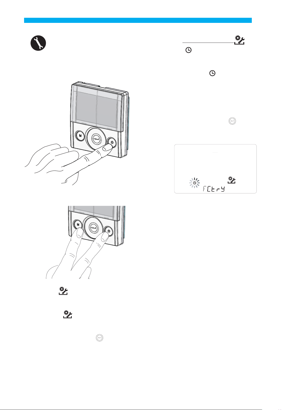
TECHNICAL MENU
1. Turn on the appliance at the ON/OFF key.
• Installer Menu
The symbol ashes on the display when the
installer menu is opened. Use the TOUCH PAD to
choose the desired function between:
- day and time setting ;
- initial setting/conguration of fans “V”(see section “COMMISSIONING”);
- Selection/Setting of the chosen weekly program
“P”(see section “COMMISSIONING”);
- FCtry (FACTORY) menu;
Press the Enter key to conrm .
2. Press the ON/OFF and “M” Menu keys at the
same time.
3. The symbol ashes on the display;
Use the TOUCH PAD to choose the desired function
between:
- Installer menu (initial setting menu);
- “PAr” parameters;
- rEAd menu;
P
V
NOTE: the FACTORY (“FCtry”) menu is for the
exclusive use of the manufacturer.
Password-protected menu
Press the“M” button once to return to parameter
selection; to exit the menu, press the “M” button
3 times.
Press the Enter key to conrm .
45
Page 46

English
• “PAr” Parameters Menu
This menu allows you to modify the operating parameters of the appliance. With the controller “ON”,
press “M” and On/O simultaneously for 3 seconds.
Select the “PAr”menu using the TOUCH PAD and
conrm by pressing “Enter”. Select the parameter to
be modied by using the TOUCH PAD and conrm by
pressing Enter”. Once the parameter is selected, the
value will be displayed. The value can be modied
using the TOUCH PAD. Press the“M” button once to
return to parameter selection; to exit the menu, press
the “M” button 3 times.
Table 1
“PAr” DESCRIPTION RANGE DEFAULT
CO2hi
CO2lo
CO2st
CO2Sr
VLO
Minimum control voltage in calibration -10% ÷ +10% See table 2
VHI
nLO
nHI
Pstd
Pbst
Percentage of standard modulation of nominal speed 100% ÷ 110% 100%
Percentage of boost/party modulation 110% ÷ 130% 130%
PnGt
Pmed
Phol
Percentage of intermediate modulation 35% ÷ 70% 45%
Percentage of minimum - holiday modulation 0 ÷ 35% 25%
Tbst
TCOOL
THEAT
Test
Tinv
SPrc
RHnSP
Cooling setpoint temperature for freeheating management 10 ÷ 30°C 26
Heating setpoint temperature for freecooling management 10 ÷ 30°C 20
Summer season transition temperature for pre-cooling management
Winter season transition temperature for antifreeze management
Percentage imbalance between ow rates -20% ÷ +20% 0%
Number of samples to calculate dynamic humidity setpoint 1 ÷ 96 96 (15 min)
Flife
HrLO
Hrst
HrHiF Shows the HrHi parameter* On ÷ O O
HrHi
Relative humidity for Minimum Humidity mode activation
Relative humidity lower limit in the comfort range *
Relative humidity upper limit in the comfort range * 40 ÷ 50 45
Relative humidity for Maximum Humidity mode activation* 60 ÷ 80 65
FLUSH
ErHs
Func
FUNCTIONS blocking operation (see dedicated paragraph)
Maximum CO2 level * 1500 ÷ 2000 ppm
Minimum CO2 level * 400 ÷ 600 ppm
Nominal CO2 level * 900 ÷1100 ppm
Full-scale CO2 * 2000 ÷ 30000 ppm
Maximum control voltage -10% ÷ +10% See table 2
Minimum speed in operation -10% ÷ +10% See table 2
Maximum speed -10% ÷ +10% See table 2
Percentage of night modulation 45% ÷ 100% 70%
Boost/Party Time 60 ÷ 240 min 180
geothermal coil
geothermal coil
Filter service life 30 ÷ 400 days 180 days
Summer Mode activation On ÷ O
Speed of
Low humidity
10 ÷ 30°C 18
10 ÷ 30°C 24
20 ÷ 45 25
1 ÷ 4 speeds
- -
1500
500
1000
2000
OFF
2 speed
* Available only if the functions feature air quality sensors
46
Page 47

Table 2
English
Model
nMAX
(rpm)
nMIN
(rpm)
Vmax
(Volt)
Vmin
(Volt)
ENY-S-170
ENY-SEL-170
ENY-SER-170
3450 588 9 4
ENY-S-270
ENY-SEL-270
ENY-SER-270
2470 220 8 3.5
ENY-S-360
ENY-SEL-360
ENY-SER-360
2850 220 7 4
ENY-S-460
ENY-SEL-460
ENY-SER-460
3200 434 7 3.22
• FUNCTIONS
BLOCK SCREEN ("Func")
From the PAr Menu you can access the "Func" screen.
Model
ENY-SP-180
ENY-SPEL-180
ENY-SPER-180
ENY-SP-280
ENY-SPEL-280
ENY-SPER-280
ENY-SP-370
ENY-SPEL-370
ENY-SPER-370
ENY-SP-460
ENY-SPEL-460
ENY-SPER-460
nMAX
(rpm)
nMIN
(rpm)
Vmax
(Volt)
Vmin
(Volt)
3570 588 9.58 4.22
2470 220 8 4.5
3150 220 10 4
3200 434 7 3.22
Using the TOUCH PAD you can select the function to
be inhibited from being used by the USER.
The functions that can be inhibited are:
- Party
- Holiday
- Manual
- AUTO
- Machine Shutdown ("OFF")
- Clock
- Weekly Programs
Press "Enter" to enable the inhibition of a specic
function, which is conrmed by the activation of the
padlock icon.
Press "M" 3 times to go back to the Main Screen.
In the User Menu, the functions inhibited by the
screen "Func" can no longer be selected.
Alongside there is a function block example (Party
mode).
47
Page 48

English
• “Read” Menu
This menu allows you to read some operating parameters of the appliance.
T1
°C
With the controller “ON”, press “M” and On/O simultaneously for 3 seconds.
Select the “rEAd” menu using the TOUCH PAD and
conrm by pressing “Enter”.
Select the parameter to be read using the TOUCH
PAD. Once you have selected the parameter, the
value will appear on the display.
Press the“M” button once to return to parameter
selection; to exit the menu, press the “M” button
3 times.
DESCRIPTION
T1
T2
T3
T4
RD1
RD2
RD3
RD4
RH
RHs
CO2
value of external air temperature probe T1
value of intake air temperature probe T2
value of stale extracted air temperature
probe T3
value of exhaust air temperature probe T4
Fan voltage
fan rpm
Air ow rate automatically controlled by fans (*)
Temperature report
detected humidity value (*)
detected dynamic humidity set point value (*)
value of CO2 detected (*)
Preheating
resistance power output (*)
T2
°C
°C
T3
°C
T4
=
Cnt
DIP
* Available only if the functions feature air quality sensors
48
Number of operating hours of the appliance
(fan hours rpm > 0)
Conguration dip switch power board
Time remaining until lter replacement
(in days)
=
1234 5678Dip n°
Page 49

ALARMS
F7
M5
F7
M5
Standard Conguration
Right Side Conguration
Below is a table for troubleshooting the faults that
may occur during operation of the machine.
English
Type of
Signal
AUTO
FROST
Description
of Fault
General Alarm. Present in case of any fault
FAN voltage/speed limits exceeded.
Faulty temperature probe
Faulty humidity/CO2 probe
Filter replacement.
Electric defrost resistance
fault
Antifreeze Alarm
T-EP Controller Error
It is recommended to enter the Read Menu to check the FAN
operating parameters and identify which FAN is not working
The faulty probe code appears next to the "thermometer"
icon. In the Read Menu the faulty sensor no longer provides
any reading.
It is recommended to enter the Read Menu to check the
probe data and identify which probe is faulty.
Replace the lters of the unit.
Check the resistance reset thermostat;
Check the electrical connections;
It is recommended to enter the Read Menu to check the
probe data and identify which probe is faulty
REFER TO
The FROST alarm is reset automatically. In order to report
the failure, the FROST string continues to ash in the hours
eld until technical support is provided.
Check the electrical connections between the controller
and the power board of the machine.
ANTIFREEZE PROTECTIVE CIRCUIT
Notes/Solution
DL3 Blinking
LED
/
4
2
6
1
3
TABLE
/
7
Servicing involving the user is limited to periodically replacing the lters. The lters must only be
replaced when indicated on the controller display
(icon ).
The unit cannot be used without lters.
• Open the front panel;
• Remove the caps (A);
• Extract the lters and replace them (B).
• Put all the components back in the opposite
order and reconnect power.
PLEASE NOTE: comply with the codes on the
filters and the type of unit connection used
(standard or right side).
USER MAINTENANCE
Always disconnect power before accessing
the unit.
B
A
• Now it is possible to switch o the icon of
the display.
•
Go to the User Setting menu, press the “M”button.
• Use the TOUCH PAD to select the icon of lter
activation .
• Press the conrm button .
• The timer to change the lters has been reset .
49
Page 50

English
INSTALLER
MAINTENANCE
The following maintenance interventions must only
be carried out by the installer or by qualied personnel:
• Inspect the lters and clean them if necessary;
• Inspect the heat exchanger and clean it if necessary;
• Inspect the fans and clean them if necessary;
• Check the condensate drain once every two years.
The following paragraph have a short description of
the maintenance interventions.
PLEASE NOTE: If maintenance is not carried out
regularly, the ventilation system might not work
properly.
• Check the heat exchanger
Check the heat exchanger once every two years.
Always disconnect power before accessing
the unit.
• Unscrew the front panel and remove it.
1
• Open the front panel
1
2
50
2
Page 51

English
• Pull the band (A) to remove the heat exchanger.
• Checking the fans
Check the fans once every two years.
Always disconnect power before accessing
the unit.
• Unscrew the front panel and remove it as
shown in the chapter on maintenance of the heat
exchanger.
- Remove the black panels (B) in front of the fans.
- Extract the fans (C) paying attention to the
electric cables.
PLEASE NOTE: to extract the fans, you must
completely remove the electric cables and their
clamped xing devices.
C
A
ATTENTION! The heat exchanger may
contain residual water.
• Inspect the condition of the heat exchanger and
clean it if necessary:
- Use a soft brush to clean the ns.
- Use a vacuum cleaner or compressor (not high
pressure) to remove lth and dust.
IMPORTANT! Always clean in the opposite direction of the air ow.
- If no more operation is necessary, ret all the
components in the opposite order and reconnect
power.
B
- Clean the fans with a soft brush for the fan
blades and use a vacuum cleaner (D) to remove dust.
D
ATTENTION! DO NOT DAMAGE THE FAN
BLADES.
- If no more operation is necessary, ret all
the components in the opposite order and
reconnect power.
51
Page 52

English
WIRING DIAGRAMS
(
machine in standard conguration)
KEY
M1-M2 = EC motor
M3 = Primary damper motor
M4 = Secondary damper motor
B1 = Outdoor air temperature probe
B2 = Supply air temperature probe
B3 = Extracted stale air temperature probe
B4 = Exhaust air temperature probe
B5-B6 = Electric resistance safety thermostats
B7 = Humidity sensor
B8 = Pressure transducer
F4 = Electric resistance safety fuse
R1 = Electric Resistance
Q1 = Relay
BK = Black
BN = Brown
BU = Blue
OG = Orange
RD = Red
WH = White
GNYE = Green/Yellow
YE = Yellow
52
Page 53
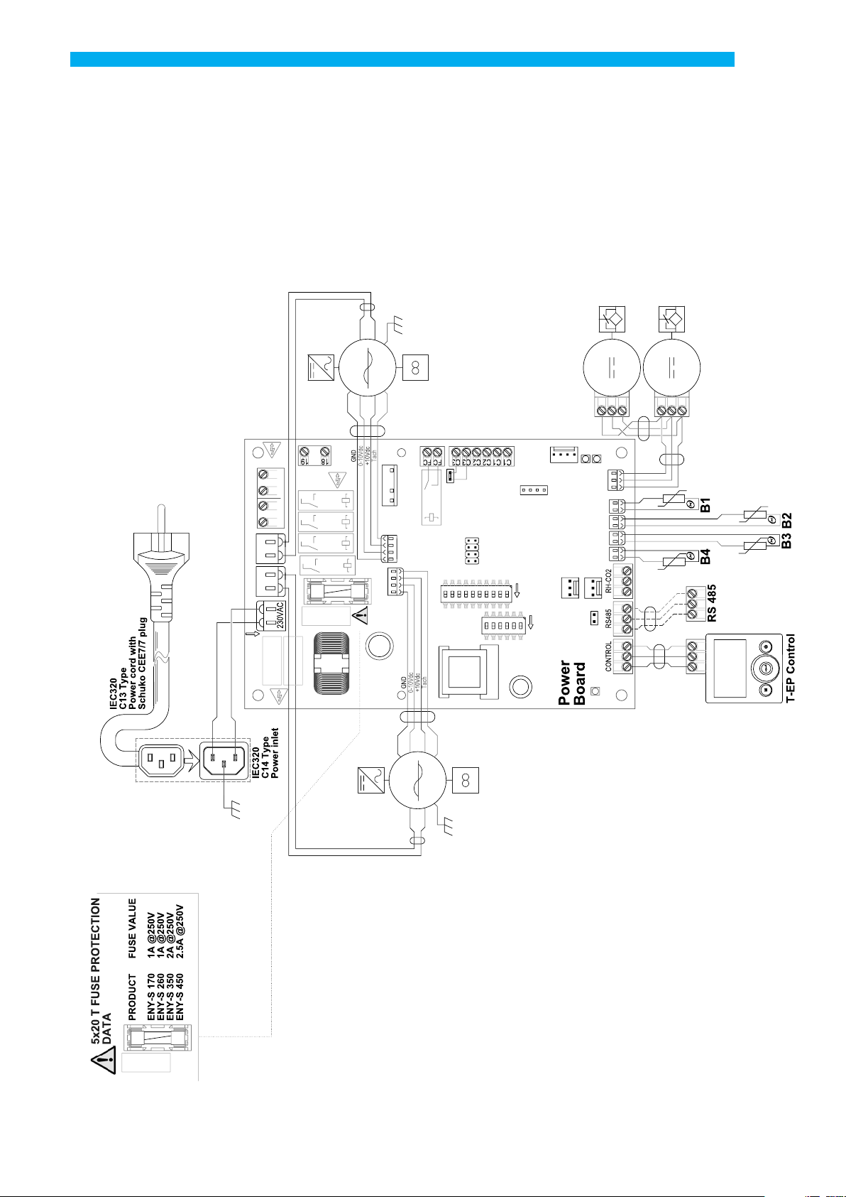
SE-0545 - ENY - S standard wiring diagram
BK
BU
GNYE
50Hz
M2
230V
YE
BU
RD
WH
FC-FC
T.Type
EH2
MC1
M12
EH1
F2
F3
F1
109876543
M24
M16
L1
N1
FAN2
FAN1
2021
2223
EH4 EH3
N
L L
N
M23
C3-C3C2-C2C1-C1
MC2
21
KD1
ON
6543
KD2
English
M4
2
1
DL1
DL3
TTL
BD
IAQ
T2T3T4 T1
97 864 5
KNX
ON
21
ON
BP
ON
MC4
321
12Vdc
3
M3
12Vdc
2
1
3
GN
WH
BN
GN
WH
BN
BK
WH
BK
WH
D+
D-
0
BK
WH
BK
WH
31 2
T.Type
DL2
BU
BN
L
N
F3
L
N
GNYE
BU
RD
YE
M1
BK
BU
WH
50Hz
230V
GNYE
53
Page 54

English
SE-0547 - ENY-S wiring diagram with preheating electric resistance
IO
ZC
RD
BU
BK
BK
BU
GNYE
50Hz
M2
230V
YE
BU
RD
WH
T.Type
EH2
M12
EH1
F2
F3
F1
2021
2223
EH4 EH3
M24
FAN2
M16
FAN1
N
L L
N
BU
BN
GNYE
L1
N1
M23
BK
BU
RD
FC-FC
C3-C3C2-C2C1-C1
MC1
109876543
MC2
KD1
6543
M4
221
DL1
DL3
TTL
BD
IAQ
T2T3T4 T1
97 864 5
21
ON
ON
21
KD2
ON
ON
KNX
BP
MC4
321
12Vdc
3
M3
12Vdc
3
1
GN
WH
BN
GN
WH
BN
BK
WH
BK
WH
D+
D-
0
BK
WH
BK
WH
31 2
T.Type
DL2
BU
BN
GNYE
L
N
F3
L
N
GNYE
BU
RD
YE
M1
BK
BU
WH
50Hz
230V
GNYE
54
Page 55

SE-0546 - ENY-SP wiring diagram
BK
BU
GNYE
50Hz
M2
230V
YE
BU
RD
WH
T.Type
EH2
F3
F1
M24
M16
L1
N1
FAN2
FAN1
2021
2223
EH4 EH3
N
L L
N
M23
English
M4
1
2
FC-FC
C3-C3C2-C2C1-C1
MC1
M12
EH1
MC2
F2
109876543
KD1
6543
21
ON
ON
21
KD2
ON
ON
IAQ
DL1
DL3
TTL
BD
T2T3T4 T1
97 864 5
KNX
BP
MC4
321
12Vdc
3
M3
12Vdc
1
3
2
GN
WH
BN
GN
WH
BN
BK
WH
BK
WH
D+
D-
0
BK
WH
BK
WH
31 2
T.Type
DL2
BU
BN
L
N
F3
L
N
GNYE
BU
RD
YE
M1
BK
BU
WH
50Hz
230V
GNYE
55
Page 56

English
SE-0548 - ENY-SP wiring diagram with preheating electric resistance
IO
ZC
RD
BU
BK
BK
BU
GNYE
50Hz
M2
230V
YE
BU
RD
WH
T.Type
EH2
M12
EH1
F2
F3
F1
2021
2223
EH4 EH3
M24
FAN2
BU
BN
GNYE
N
M16
L L
FAN1
N
L1
N1
M23
RDBUBK
FC-FC
C3-C3C2-C2C1-C1
MC1
109876543
MC2
KD1
6543
12Vdc
GN
WH
BN
GN
WH
BN
BK
WH
BK
WH
M3
321
12Vdc
D+
D-
0
21 3
BK
WH
BK
WH
M4
123
DL1
DL3
TTL
BD
IAQ
T2T3T4 T1
97 864 5
21
ON
ON
21
KD2
ON
ON
KNX
BP
MC4
321
T.Type
DL2
BU
BN
GNYE
L
N
F3
L
N
GNYE
BU
YE
M1
BK
RD
BU
WH
50Hz
230V
GNYE
56
Page 57

Additional wiring diagrams
CARBON DIOXIDE (CO2)
REMOTE SENSOR
Interface diagram
English
BP
DL2
321
MC4
CO2
KNX
CO2
864 5
T3T4
97
57
Page 58

P
Oggetto: Dichiarazione di conformità UE
Object: EU Declaration of conformity
La presente dichiarazione di conformità è rilasciata sotto la responsabilità esclusiva del fabbricante.
This declaration of conformity is issued under the exclusive responsibility of the manufacturer.
Prodotto: Energy Smart - Recuperatori Versione Verticale
roduct: Energy Smart - Vertical Recovery Units
ENY-SP-180, ENY-SP-280, ENY-SP-370, ENY-SP-460,
ENY-SPEL-180, ENY-SPEL-280, ENY-SPEL-370, ENY-SPEL-460,
ENY-SPER-180, ENY-SPER-280, ENY-SPER-370, ENY-SPER-460,
ENY-SPM-180, ENY-SPM-280, ENY-SPM-370, ENY-SPM-460,
Modello / Pattern:
ENY-SPMEL-180, ENY-SPMEL-280, ENY-SPMEL-370, ENY-SPMEL-460,
ENY-SPMER-180, ENY-SPMER-280, ENY-SPMER-370, ENY-SPMER-460,
ENY-S-170, ENY-S-270, ENY-S-360, ENY-S-460,
ENY-SEL-170, ENY-SEL-270, ENY-SEL-360, ENY-SEL-460,
ENY-SER-170, ENY-SER-270, ENY-SER-360, ENY-SER-460.
al quale questa dichiarazione si riferisce, è conforme alle seguenti norme:
to which this declaration relates is in conformity with the following standards or other normative document(s):
EN 60335-1 (2012) + A11 (2014)
EN 60335-2-80
EN 62233
EN 55014-1
(2003) + A1 (2004) + A2 (2009)
(2008)
(2006) +A1 (2009) + A2 (2011)
EN 55014-2 (2015)
EN 61000-3-2
EN 61000-3-3
EN 50581
(2014)
(2013)
(2012-09)
Regulation (UE) 1253/14
Regulation (UE) 1254/14
Regulation (EC) 1907/2006
L’oggetto della dichiarazione di cui sopra è conforme alla pertinente normativa di armonizzazione dell’Unione.
The object of the declaration described above is in conformity with the relevant Union harmonization legislation.
2014/35/UE 2014/30/UE 2006/42/EC 2011/65/EC
Il fascicolo tecnico è costituito presso: Sabiana S.p.A. Via Piave 53, 20011 Corbetta (MILANO-ITALY)
The technical file is made at: Sabiana S.p.A. Via Piave 53, 20011 Corbetta (MILANO-ITALY)
Corbetta, 23/10/2018
 Loading...