


LONG DISTANCE RADIO (LDR)
USER MANUAL
Version 0.002
Confidential
LONG DISTANCE RADIO USER MANUAL
Copyright Notice
No part of this document may be photocopied, reproduced or translated without the prior written consent of
ARAM Systems Ltd. This document and the information contained in this document may not be transferred,
disclosed or otherwise provided to third parties.
This document is for informational and instructional purposes. ARAM Systems Ltd. reserves the right to make
changes in specifications and other information contained in this publication without prior notice, and the reader
should, in all cases, consult ARAM Systems Ltd. to determine whether any changes have been made.
The terms and conditions governing the sale and licensing of ARAM Systems Ltd. products are set forth in the
written contracts between ARAM Systems Ltd. and its customers. No representation or other affirmation of fact
contained in this publication shall be deemed to be a warranty or give rise to any liability of ARAM Systems Ltd.
whatsoever.
Disclaimer
ARAM Systems Ltd. makes no warranty of any kind with regard to this material, including but not limited to, the
implied warranties or merchantability and fitness for a particular purpose.
ARAM Systems Ltd. shall not be liable for any incidental, indirect, special, or consequential damages whatsoever,
(including but not limited to lost profits) arising out of or related to this publication or the information contained in
it, even if ARAM Systems Ltd. has been advised of the possibility of such damages.
Revision History
VERSION
0.000 March
0.001 October
0.002 October
DATE AUTHOR CHANGES
HH BEGIN DRAFT
31, 2008
HH
27, 2008
HH
29, 2008
Add a statement per FCC PART 15.19 and PART 15.21
Change page 12 all Operating Frequencies to Preset
Copyright © ARAM Systems Ltd., 2008
LONG DISTANCE RADIO USER MANUAL, V0.002
Specifications subject to change without notice
2

Confidential
LONG DISTANCE RADIO USER MANUAL
LONG DISTANCE RADIO (LDR) ..................................................................................................................1
USER MANUAL.............................................................................................................................................1
Version 0.002 ................................................................................................................................................1
1
2
3
4
5
6
7
OVERVIEW ............................................................................................................................4
HIGH LEVEL SYSTEM ARCHITECTURE .............................................................................4
LDR UNIT...............................................................................................................................5
3.1
CONNECTORS AND LED DISPLAYS ...................................................................5
3.2
STATUS LED..........................................................................................................5
3.3
RADIO STATUS LED .............................................................................................6
3.4
7-SEGMENT LED DISPLAY...................................................................................7
TYPICAL SETUPS .................................................................................................................8
ANTENNAS..........................................................................................................................10
FCC/INDUSTRY CANADA NOTICE ....................................................................................11
6.1
STATEMENT ACCORDING TO FCC PART 15.19 ..............................................11
6.2
STATEMENT ACCORDING TO FCC PART 15.21 ..............................................11
LDR SPECIFICATIONS .......................................................................................................11
Copyright © ARAM Systems Ltd., 2008
LONG DISTANCE RADIO USER MANUAL, V0.002
Specifications subject to change without notice
3
Confidential
LONG DISTANCE RADIO USER MANUAL
1 OVERVIEW
The purpose of this radio system is to provide a rugged VHF data link between various components of the ARAM
seismic data acquisition system. Emphasis is placed on the “Vibroseis” market, where mobile excitation source
equipment needs to be connected with the greater data acquisition network and the Central Recording Unit (CRU).
The actual seismic spread can cover over 100 square kilometers over many different types of terrain, making the
need for a long distance, (24km line of sight), radio that is very robust. Typically the vibrators operate in groups of 4,
and each vibrator generates about 125kbits/sec of information, making the overall payload bandwidth at least
500kbits/sec.
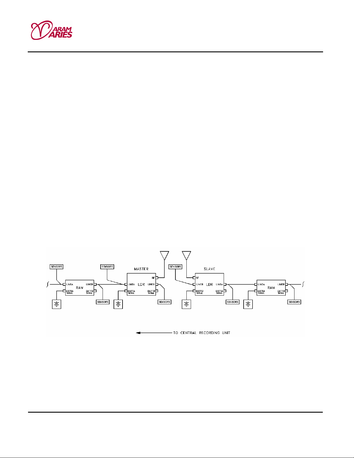
2 HIGH LEVEL SYSTEM ARCHITECTURE
An LDR takes on one or two possible roles: Master or Slave. On any one operating frequency there is only one
Master, and a configurable number of slaves. Masters are connected by the cabled ARAM network to the CRU
(Central Record Unit) while Slaves are connected into the greater system through the LDR RF link and the
Master.
The LDR will interface with ARAM’s “R-Lines” much like a RAM unit, unlike a RAM, however, the LDR will have a
third (RF) port. The LDR system will operate in a master/slave relationship (as opposed to a peer to peer
configuration). More than one slave is possible. Data flow is predominantly from the slave side to the master.
From a manufacturability standpoint, however, the master and slave units are to be physically identical. The LDR
system may be deployed in a “back-up-to-cable” role where the radio system does not operate unless cable(s)
develop impairments.
Copyright © ARAM Systems Ltd., 2008
LONG DISTANCE RADIO USER MANUAL, V0.002
Specifications subject to change without notice
4

LONG DISTANCE RADIO USER MANUAL
3 LDR UNIT
3.1 CONNECTORS AND LED DISPLAYS
Battery
connectors
R-line
connector
Confidential
Status LED
Battery
connectors
R-line
connector
RF
connector
7-Segment
LED display
Radio
status LED
3.2 STATUS LED
Various combinations of these LED indicators will occur during operation. For example, during a shot, a LDR that
is powered up and acquiring data properly will display a power LED, and a flashing green LED on the CRU side. If
that LDR is not the last active LDR on the line, it will also display a green LED on the Line Side indicating another
LDR is connected. Green LED’S on both sides will blink when data is moving.
Copyright © ARAM Systems Ltd., 2008
LONG DISTANCE RADIO USER MANUAL, V0.002
Specifications subject to change without notice
5

Confidential
LONG DISTANCE RADIO USER MANUAL
CRU SIDE LINE SIDE DESCRIPTION
⇒ No Power.
⇒ May indicate faulty or disconnected battery, no telemetry connection to the CRU, or CRU has
powered down the line.
⇒ Powered Up.
⇒ Pilot Voltage on any of the digital transmission pairs will turn the amber LED on.
⇒ Amber power LED indicates which side the CRU is on.
⇒ Normally indicates functioning battery and continuity of telemetry connection to the CRU.
⇒ Blinking amber power LED indicates that the RAM, LTU, or Repeater has been placed in
repeater mode by the CRU and that the module is receiving interrogates from the CRU. In this case
both transceivers are placed in repeater mode.
⇒ Blinking green LED on the CRU side indicates that the module is receiving interrogates from
the CRU. It also indicates data on all digital pairs is being transmitted.
⇒ A solid green LED on the Line Side indicates that the module can detect continuity on the
telemetry connection to the next module. This does not mean a battery is connected to that module.
⇒ If the CRU is detected on both digital pairs, the Line Side must detect continuity on both digital
pairs for the green LED to be on.
⇒ A Blinking green LED on the Line Side indicates that the module is receiving recognizable data
on both digital pairs from another module on the Line Side.
⇒ A solid red LED on the Line Side indicates the CRU has configured the module and shut down
the Pilot Voltage to the Line Side.
⇒ This prevents modules on the Line Side from receiving the power up signal.
⇒ This indicates the end of the network.
Note: Circle = LED off, Solid = LED on.
The above describes the operation of a single LED. Combinations of LED patterns will occur in regular operation.
In Blink mode the LED is turning on and off at a steady, repetitious pattern about 4 times per second.
3.3 RADIO STATUS LED
Three status LEDs are mounted on the left side of the radio assembly PCB. These LEDs are to convey the
status of the radio assembly.
The LED’S are Amber (Link Status), Green (Receive Activity), and RED (Transmit Activity).
Copyright © ARAM Systems Ltd., 2008
LONG DISTANCE RADIO USER MANUAL, V0.002
Specifications subject to change without notice
6

Confidential
LONG DISTANCE RADIO USER MANUAL
INDICATION DESCRIPTION
⇒ No Power or Sleep state.
⇒ May indicate faulty or disconnected battery, no telemetry connection to the CRU, or CRU has powered down the
line.
⇒ Active state.
⇒ Normally indicates functioning battery and continuity of wireless telemetry connection to the CRU.
⇒ Sniff state (blink characteristics are LED on for about 125ms per second).
⇒ Receiving data (blink characteristics are LED turns on and off about 4 times per second).
⇒ Transmitting data (blink characteristics are LED turns on and off about 4 times per second).
Note: Circle = LED off, Solid = LED on.
3.4 7-SEGMENT LED DISPLAY
The 7-segment LED display indicates the received signal strength. The display indication has been calibrated as
follows:
• 0-3 Marginal (20dB or less of margin to receiver sensitivity limit)
• 4-6 Good (20 – 40 dB of margin)
• 7-9 Strong ( in excess of 40 dB margin; transmit power could be reduced)
Copyright © ARAM Systems Ltd., 2008
LONG DISTANCE RADIO USER MANUAL, V0.002
Specifications subject to change without notice
7

24V
24V
24V
24V 24V
24V
24V
24V
24V
24V
24V
4 TYPICAL SETUPS
Confidential
LONG DISTANCE RADIO USER MANUAL
LDR
RAM
R-
Line
RAM
LDR
RAM
Battery
Battery Battery
LDR
LDR
LDR
RAM
RAM
RAM
Copyright © ARAM Systems Ltd., 2008
LONG DISTANCE RADIO USER MANUAL, V0.002
Specifications subject to change without notice
8

• Maximum range may be achievable only under ideal rural conditions (i.e. flat open treeless terrain /
minimum noise and interference at receiver site) using (a) a directional/gain antenna and (b) a mast up to
15m in height at the master location.
• The slave antenna(s) shall be limited to non-directional / non-gain types mounted 3m above the ground.
If you want to test LDR by connecting two units through coaxial cables, a 10W, 60dB (Minimum)
attenuator is needed.
Confidential
LONG DISTANCE RADIO USER MANUAL
CAUTION
Attenuator
10W
60dB Min.
Copyright © ARAM Systems Ltd., 2008
LONG DISTANCE RADIO USER MANUAL, V0.002
Specifications subject to change without notice
9

5 ANTENNAS
Candidates:
• Omni-directional
1. Antenex http://www.antenex.com/index051206.htm
Confidential
LONG DISTANCE RADIO USER MANUAL
Model
B2003
200 - 225 MHz
2. GAM
SS-220 220Mhz 25” whip, optional Magnetic mount
3. TG series
http://www.gamelectronicsinc.com/tg.html
• Yagi antennas
1. Antenex YS2165
Frequency
http://www.gamelectronicsinc.com/mini.html
Center Freq Gain
Tunable
http://www.antenex.com/index051206.htm
3 dB
Overall Length
35
Whip Style MSRP
33” Straight
$36.66
Copyright © ARAM Systems Ltd., 2008
LONG DISTANCE RADIO USER MANUAL, V0.002
Specifications subject to change without notice
10

Confidential
LONG DISTANCE RADIO USER MANUAL
SILVER SERIES VHF MODELS
Model Finish
Frequency
Center Freq
Elements
Gain
FB Ratio
MSRP
YS2165 Silver 216 - 225 MHz
2. SINCLAIR SY206EB http://
Yagi directional antenna, 9.5 dBd gain, 138-225 MHz
Tunable
www.sinctech.com/catalog/resources/pdf/SY206EB-dm.pdf
5
9.2 dBd 20 dB
6 FCC/INDUSTRY CANADA NOTICE
6.1 STATEMENT ACCORDING TO FCC PART 15.19
FCC compliance is not valid if customer modifies product
.
6.2 STATEMENT ACCORDING TO FCC PART 15.21
Modifications not expressly approved by ARAM could void the user's authority to operate the
equipment.
$163.80
7 LDR SPECIFICATIONS
Functions:
The purpose of this radio system is to provide a rugged VHF data link between various components of the ARAM
seismic data acquisition system. Emphasis is placed on the “Vibroseis” market, where mobile excitation source
equipment needs to be connected with the greater data acquisition network and the Central Recording Unit (CRU).
Copyright © ARAM Systems Ltd., 2008
LONG DISTANCE RADIO USER MANUAL, V0.002
Specifications subject to change without notice
11

Confidential
LONG DISTANCE RADIO USER MANUAL
Frequency Range:
In US and CANADA: 217 - 218 MHz, and 219 - 220 MHz.
Other countries: compliance with local regulations
Operating Frequencies:
The default operating frequencies are:
Preset-1 (217.171592 MHz)
Preset-2 (217.522678 MHz)
Preset-3 (217.873763 MHz)
Preset-4 (219.127641 MHz)
Preset-5 (219.478727 MHz)
Preset-6 (219.829812 MHz)
Other channels can be supported subject to a frequency step size of 50.16 kHz and minimum offset from upper
and lower band edges of 170 kHz.
Channel Plan:
For any given application all radios operate on the same channel using Time Division Duplex.
Operating Bandwidth:
325KHz
Modulation Scheme:
BPSK for packet setup, OQPSK for payload
BPSK at 276.48 kbps
OQPSK at 552.96 kbps
RF Output Power
The RF amplifier will be capable of running from 10dBm (10mW) to 37dBm (5W) in approximately 1dB steps.
A maximum power level can be configured to ensure that the transmitter does not exceed the limits specified in a
particular license.
RF Output Impedance: 50 Ω.
Power Supply
Operating power voltage: 21VDC to 28VDC, 4 battery connectors
Use 24V (nominal) SLA battery pack.
Physical specifications
- Material: Aluminium.
- Size: 305x137x169 mm
- Weight: 4.8 kg
Environmental specifications
- Operating Temperature: -40° to +70°C.
- Storage Temperature: -45° to +85°C.
- Humidity: 0 – 100%
Copyright © ARAM Systems Ltd., 2008
LONG DISTANCE RADIO USER MANUAL, V0.002
Specifications subject to change without notice
12

Confidential
LONG DISTANCE RADIO USER MANUAL
7236–10 Street NE, Calgary, Alberta T2E 8X3, Canada
Phone 1-403-537-2100 Fax 1-403-537-2101
Web site www.aram.com
Copyright © ARAM Systems Ltd., 2008
LONG DISTANCE RADIO USER MANUAL, V0.002
Specifications subject to change without notice
13
 Loading...