

Page 1

DUAL-WAN GIGABIT VPN ROUTER
USER INTERFACE MANUAL
Models:
AN-310-RT-4L2W
Manual Version
200915-1723
Page 2

Araknis Networks® 310 Series Router
User Interface Manual
Federal Communication Commission Interference Statement
Federal Communication Commission Interference Statement
This equipment has been tested and found to comply with the limits for a Class B digital device, pursuant
to Part 15 of the FCC Rules. These limits are designed to provide reasonable protection against harmful
interference in a residential installation. This equipment generates, uses and can radiate radio frequency
energy and, if not installed and used in accordance with the instructions, may cause harmful interference
to radio communications. However, there is no guarantee that interference will not occur in a particular
installation. If this equipment does cause harmful interference to radio or television reception, which can be
determined by turning the equipment o and on, the user is encouraged to try to correct the interference
by one of the following measures:
• Reorient or relocate the receiving antenna.
• Increase the separation between the equipment and receiver.
• Connect the equipment into an outlet on a circuit dierent from that to which the receiver is connected.
• Consult the dealer or an experienced radio/TV technician for help.
FCC Caution: Any changes or modifications not expressly approved by the party responsible for compliance
could void the user’s authority to operate this equipment.
This device complies with Part 15 of the FCC Rules. Operation is subject to the following two conditions: (1)
This device may not cause harmful interference, and (2) this device must accept any interference received,
including interference that may cause undesired operation.
This device is designed for indoor use only.
IMPORTANT NOTE:
FCC Radiation Exposure Statement:
This equipment complies with FCC radiation exposure limits set forth for an uncontrolled environment.
This equipment should be installed and operated with minimum distance 20cm between the radiator &
your body.
Industry Canada Statement
This device complies with Industry Canada’s licence-exempt RSSs. Operation is subject to the following
two conditions:
1. This device may not cause interference; and
2. This device must accept any interference, including interference that may cause undesired
operation of the device.
Le présent appareil est conforme aux CNR d’Industrie Canada applicables aux appareils radio exempts de
licence. L’exploitation est autorisée aux deux conditions suivantes : (1) l’appareil ne doit pas produire de
brouillage, et (2) l’utilisateur de l’appareil doit accepter tout brouillage radioélectrique subi, même si le
brouillage est susceptible d’en compromettre le fonctionnement.
Caution:
(i) The device for operation in the band 5150–5250 MHz is only for indoor use to reduce the potential for
harmful interference to co-channel mobile satellite systems;
(ii) For product available in the USA/Canada market, only channel 1–11 can be operated. Selection of other
channels is not possible.
-Return to Table of Contents-
© 2020 Araknis Networks
2
®
Page 3

Araknis Networks® 310 Series Router
User Interface Manual
FCC Warning
Avertissement:
(i) Les dispositifs fonctionnant dans la bande 5150-5250 MHz sont réservés uniquement pour une utilisation
à l’intérieur afin de réduire les risques de brouillage préjudiciable aux systèmes de satellites mobiles utilisant
les mêmes canaux;
(ii) Pour les produits disponibles aux États-Unis / Canada du marché, seul le canal 1 à 11 peuvent être
exploités. Sélection d’autres canaux n’est pas possible.
Radiation Exposure Statement:
This equipment complies with ISED radiation exposure limits set forth for an uncontrolled environment.
This equipment should be installed and operated with minimum distance 63cm between the radiator &
your body.
Déclaration d’exposition aux radiations:
Cet équipement est conforme aux limites d’exposition aux rayonnements ISED établies pour un
environnement on contrôlé. Cet équipement doit être installé et utilisé avec un minimum de 63 cm de
distance entre la source de rayonnement et votre corps.
FCC Warning
Changes or modifications not expressly approved by the party responsible for compliance could void the
user’s authority to operate the equipment. This device complies with Part 15 of the FCC Rules. Operation
is subject to the following two conditions:
• This device may not cause harmful interference, and
• This device must accept any interference received, including interference that may cause undesired
operation.
(i) Les dispositifs fonctionnant dans la bande 5150-5250 MHz sont réservés uniquement pour une utilisation
à l’intérieur afin de réduire les risques de brouillage préjudiciable aux systèmes de satellites mobiles utilisant
les mêmes canaux;
(ii) Pour les produits disponibles aux États-Unis / Canada du marché, seul le canal 1 à 11 peuvent être
exploités. Sélection d’autres canaux n’est pas possible.
CE Warning
This is a product with CE certification. In a domestic environment, this product may cause radio interference,
in which case the user may be required to take adequate measures.
The device complies with ISED’s license-exempt RSSs and Canada ICES-OO3.
CE Statement
This equipment complies with EU radiation exposure limits set forth for an uncontrolled environment. This
equipment should be installed and operated with minimum distance 20 cm between the radiator & your
body.
All operational modes:
2.4GHz: 802.11b, 802.11g, 802.11n (HT20), 802.11n (HT40), 802.11ac (VHT20), 802.11ac (VHT40)
5GHz: 802.11a, 802.11n (HT20), 802.11n (HT40), 802.11ac (VHT20), 802.11ac (VHT40), 802.11ac (VHT80)
-Return to Table of Contents-
© 2020 Araknis Networks
3
®
Page 4

Araknis Networks® 310 Series Router
User Interface Manual
Certications
The frequency and the maximum transmitted power in EU are listed below:
2412-2472MHz: 19.90 dBm
5180-5240MHz: 22.90 dBm
The device is restricted to indoor use only when operating in the 5150 to 5350 MHz frequency range..
AT BE BG HR CY CZ DK
EE FI FR DE EL HU IE
IT LV LT LU MT NL PL
PT RO SK SI ES SE UK
Certifications
-Return to Table of Contents-
4
© 2020 Araknis Networks
®
Page 5
Araknis Networks® 310 Series Router
User Interface Manual
About this Manual
About this Manual
This manual provides installers and end users with current information regarding the installation, setup,
use, and maintenance of the product. The symbols below identify important information:
Pro Tip – Pro tips provide extra value, utility, or ease of use. Pro tips may also link to extra
information that provide a better understanding of the application, technology or use of the
feature in question. These items are added for your convenience.
Note – Notes emphasize important information that does not regard the safety of the equipment
or user. Notes usually contain ancillary information or a step in the process, that, if missed, causes
additional work to overcome.
Caution – The caution symbol indicates information vital to the safety of the product. Failing to
follow a caution usually results in permanent damage to the equipment, which is not covered by
the warranty.
Warning – Warnings are vital to the personal safety of the installer or end user. Not following a
warning can result in serious injury or death of the installer or end user, as well as permanent
damage to the equipment.
-Return to Table of Contents-
5
© 2020 Araknis Networks
®
Page 6

Araknis Networks® 310 Series Router
User Interface Manual
About this Manual
Table of Contents
FederalCommunicationCommissionInterferenceStatement
IndustryCanadaStatement
FCCWarning
CEWarning
Certifications
AboutthisManual
LANPortsonthe
WANPortsonthe
MenuOverview
StatusSystem
StatusClients&Services
StatusPorts
SettingsSystem
SettingsWAN
SettingsLAN
SettingsFirewall
SettingsDDNS
SettingsPortForwarding
SettingsSecurity
Tools
AdvancedStaticRoute
AdvancedNAT
AdvancedVLANs
AdvancedVPN
AdvancedIPV
AdvancedLocalDNS
AdvancedSNMP
AdvancedACLs
AdvancedQoS
AdvancedBandwidthControl
SystemLog
Specifications
-YearLimitedWarranty
TechnicalSupport
-Return to Table of Contents-
© 2020 Araknis Networks
6
®
Page 7

Araknis Networks® 310 Series Router
User Interface Manual
LAN Ports on the 310
LAN Ports on the 310
The AN-310 router has limited support for communications between the LAN 1–3 port grouping, and the
LAN 4 port. As a result, we recommend you use LAN 4 as a non-overlapping network
This document provides guidance for the best practices for specific installation scenarios.
What Is Limited?
These limitations include:
• Multicast to support any auto-discovery protocols like SDDP (Control 4), AirPlay, Sonos, etc.
• QoS to support services like VoIP systems
Use Case: Router-on-a-Stick Topology
Our recommended procedure is to attach one dedicated switch to the router to handle trac. Thus the
connections run from the modem to the router, and then to the master switch. From there the cables run
to other switches, WAPs, and host devices.
In this use case, use the LAN 4 port, which supports higher WAN-LAN throughput than the others:
• LAN 4: WAN-LAN 1Gbps unidirectional, 2Gbps bidirectional (1Gbps up, 1Gbps down, concurrently.)
• LAN 1–3: WAN-LAN 1Gbps unidirectional, 1.2Gbps bidirectional (600Mbps up, 600Mbps down
concurrently.)
Use Case: Router Using Multiple Ports
If you are using the router as a switch as well, then we recommend the following:
• Use LAN 1–3 for your networking needs. These three ports communicate together well and your
network will function as expected.
• Use LAN 4 only if you have a secondary non-overlapping network that you have set up using VLAN
or subnet. Examples include a surveillance subnet or a separate network or the guest house.
WAN Ports on the 310
WAN 2 is Now Enabled
For previous router buyers please remove the sticker.
LAN 4 Can Now be Used as WAN 3
See Settings > LAN for information on enabling this feature.
Load Balancing Across all WAN Ports
The AN-310 router uses session based packet routing and does not aggregate the total bandwidth multiple
WAN ports. For example:
An example of a session would be a speed-test or video call from a single device.
When running a speed-test on multiple devices (eg. laptop, cellular, etc.), you are running multiple sessions.
-Return to Table of Contents-
© 2020 Araknis Networks
7
®
Page 8

Araknis Networks® 310 Series Router
User Interface Manual
WAN Ports on the 310
The 310-router eectively load balances across sessions, choosing a singular WAN for any given session.
A
B
C
-Return to Table of Contents-
8
© 2020 Araknis Networks
®
Page 9

Araknis Networks® 310 Series Router
User Interface Manual
Menu Overview
Menu Overview
A - Main Navigation Panel
Use the collapsible Status, Settings, Tools, Advanced, and System Log headings (and their submenus) to
configure and maintain the router. The green bar and gray highlight shows which header is active.
B - Top Bar
The top bar displays
• the system uptime (in days, hours minutes, and seconds),
• the system time,
• the connection status to the OvrC server, and
• the memory and CPU used.
To the right are two icons that you can click to restart and to log out, respectively.
C - Main Window
This displays the currently selected window, as indicated by the green lettering in the navigation panel.
-Return to Table of Contents-
9
© 2020 Araknis Networks
®
Page 10

Araknis Networks® 310 Series Router
User Interface Manual
Status > System
Status > System
The System Status screen provides a real-time summary of router system information, and is the first
screen that appears when you log in to the router web interface. Use the screen to verify settings and
operation of your device.
System Information Section
System Name: The user-assigned name for the device. This serves as the DHCP hostname of the device
(shown when scanning the network). Use this to dierentiate similar devices on your network.
Model Number: This is the part number for the router (as shown on our website).
Service Tag: The internal tracking number used to track every Araknis Networks product sold. This is
required to claim the device on OvrC.
Firmware Version: The version installed on the router. Keep this current using OvrC.
WAN# MAC Address: The unique Media Access Control (MAC) address for each WAN port.
LAN MAC Address: MAC address of the router. The MAC address is used to configure OvrC access.
Port Overview Section
This gives an at-a-glance status for each port on the router.
Each port is color-coded based on its negotiated speed:
• Gray: Not connected to a device, or the connected device has not negotiated a speed.
• Orange: 10/100Mbps connection is active.
• Green: 1Gbps connection is active.
• Red: Port has been disabled by the user in the web interface settings.
Note – LAN4 doubles as WAN3 and will appear to the right of WAN2, when configured as such.
-Return to Table of Contents-
© 2020 Araknis Networks
10
®
Page 11

Araknis Networks® 310 Series Router
User Interface Manual
Status > System
Port Status Section
This provides detailed information for each port on its own line. These can be configured under Settings
> LAN > LAN Settings.
Interface: Designates the physical port on the router.
Name: Name used to identify each port.
Speed: User-selected or device-negotiated port speed.
Duplex: Displays the duplex mode of the port.
WAN Status Section
This displays current information about the status of the WAN interfaces. It updates in real time.
Two key buttons are at the bottom of each WAN card.
Note – WAN3 appears as a WAN card if LAN4 has been configured as a WAN port.
-Return to Table of Contents-
© 2020 Araknis Networks
11
®
Page 12
Araknis Networks® 310 Series Router
User Interface Manual
Status > System
Release Button: Click to release the current WAN IP address back to the DHCP pool and receive a new one.
Renew Button: Click to renew the current WAN DHCP connection. The WAN IP address may or may not
change.
Note – The Release and Renew buttons control the network IP address.
Interface: Each WAN has its own table.
IP Address: WAN IP address of the connection.
Subnet Mask: WAN subnet mask.
Default Gateway: WAN gateway IP address.
DNS 1: WAN primary domain name server.
DNS 2: WAN secondary domain name server.
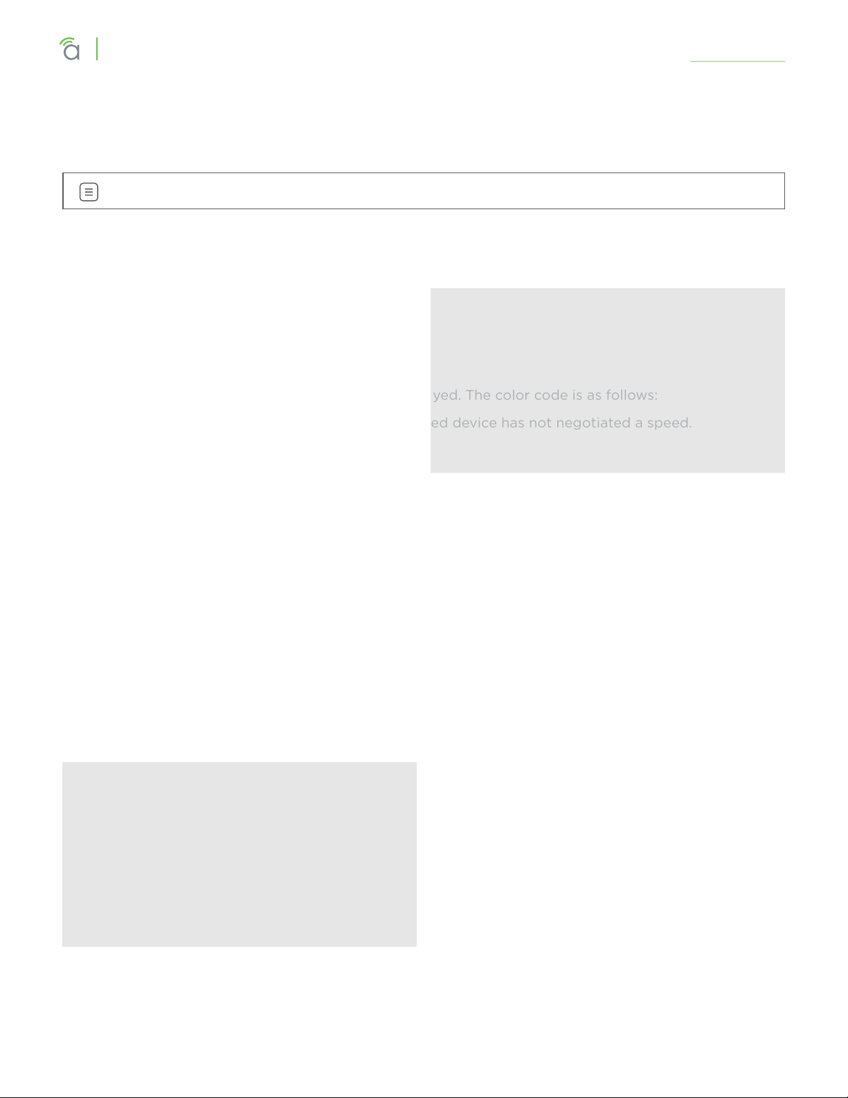
At the very bottom, the WAN’s current speed is displayed. The color code is as follows:
• Gray: Not connected to a device, or the connected device has not negotiated a speed.
• Orange: 10/100Mbps connection is active.
• Green: 1Gbps connection is active.
• Red: Port has been disabled by the user in the web interface settings.
-Return to Table of Contents-
12
© 2020 Araknis Networks
®
Page 13

Araknis Networks® 310 Series Router
User Interface Manual
Status > Clients & Services
Status > Clients & Services
This section describes the router firewall services, VPN services, attached clients, and port forwarding
settings that are currently in use. This is where you can locate devices are (via IP/DHCP reservation) and
determine which services could be aecting system performance.
Despite the appearance, this table is information only; you cannot adjust settings here. To adjust the
settings, go to Settings > Firewall.
Firewall Status
SPI (Stateful Packet Inspection): See whether the SPI firewall setting is on or o.
DoS (Denial of Service): See whether the DoS firewall setting is on or o.
Block WAN Request: See whether the Block WAN Request firewall setting is on or o.
Remote Management: See whether the Remote Management firewall setting is on or o.
VPN Tunnel Status Section
A virtual private network (VPN) provides a connection between dierent networks through a secure tunnel
over the Internet. Data sent through the VPN tunnel is encrypted for privacy even when connected to a
public or shared network that isn’t secure. VPNs are commonly used to send data between networks in
dierent geographical locations that have no dedicated physical connection.
The router can support a maximum of twenty OpenVPN, fifty IPSec, and twenty PPTP tunnels. All three
types can be active simultaneously.
This router features a built-in OpenVPN server for secure, easily configured access to the network (via
the Internet) from devices with an OpenVPN client application. OpenVPN communicates using encrypted
SSL/TLS channels between networks that the hide trac from other devices on the Internet.
-Return to Table of Contents-
© 2020 Araknis Networks
13
®
Page 14

Araknis Networks® 310 Series Router
User Interface Manual
Status > Clients & Services
The router must be configured for each OpenVPN account to be used. Client applications are available for
PC and Mac computers and iOS and Android mobile devices.
We recommend that you do not use PPTP. The technology is old and does not use encryption.
Clients Overview Section
This shows the number of attached devices, as well as how many are static vs. DHCP.
DHCP Status Section
This ARP table tracks every device connected to your network, whether it has a DHCP address or a static
IP address. In addition, the table tracks whether the device is online or oine.
Client Table Section
The client table section uses an ARP table to show all clients, their IP addresses (both DHCP and static),
and their MAC addresses. The 310 models can support up to 500 client devices.
Click to sort the table on any column. The Show drop-down in the top right filters the list.
The color bar at the left end of each line shows whether that client is up (green) or down (gray).
For DHCP addresses, click on the clock icon to show the remaining lease time.
To reserve a DHCP address, click on the + icon to the left of the trash can icon.
Clicking the trash can removes that device’s DHCP assignment. You’ll need to reboot the device to have it
request a new IP address from the router.
-Return to Table of Contents-
14
© 2020 Araknis Networks
®
Page 15
Araknis Networks® 310 Series Router
User Interface Manual
Port Forwarding Section
This lists all of the port forwarding rules in place.
See Settings > Port Forwarding for information on setting these rules.
Status > Clients & Services
-Return to Table of Contents-
15
© 2020 Araknis Networks
®
Page 16

Araknis Networks® 310 Series Router
User Interface Manual
Status > Ports
Port Overview Section
This gives an at-a-glance status for each port on the router.
Each port is color-coded based on its negotiated speed:
• Gray: Not connected to a device, or the connected device has not negotiated a speed.
• Orange: 10/100Mbps connection is active.
• Green: 1Gbps connection is active.
Status > Ports
• Red: Port has been disabled by the user in the web interface settings.
Note – LAN4 doubles as WAN3 and will appear to the right of WAN2, when configured as such.
Port Status Section
These can be configured under Settings > LAN.
Interface: Each physical port has its own row.
Name: Name used to identify each port.
Speed: User-selected or device-negotiated port speed.
Duplex: Displays the duplex mode of the port.
VLAN ID: The ID number of the VLAN.
Sent: The quantity of data sent through the port since the last time it was powered on.
Received: The quantity of data received by the port since the last time it was powered on.
Errors: The number of data transmission errors since the last time it was powered on.
-Return to Table of Contents-
© 2020 Araknis Networks
16
®
Page 17

Araknis Networks® 310 Series Router
User Interface Manual
Settings > System
System Settings Section
Here you can adjust the router’s name and IP address.
Settings > System
Names can be up to 63 characters long, and can contain letters, numbers, hyphens, underscores, and
periods. It cannot contain spaces.
The IP can be provided in either IPv4 or IPv6.
• If IPv4, this links to the Gateway IP Address (Settings -> LAN) of the default card
• If IPv6, this links to the IPv6 Address (Advanced -> IPv6)
The System Subnet Mask is not editable on this page. It is calculated from the router’s IP address.
Also, if the LED lights bother you, you can switch them o here (except for the power light).
Time Settings
NTP: By default, the router checks the time automatically, using the NIST (National Institute of Standards
and Technology) servers to synchronize to Coordinated Universal Time. This provides an accurate and
-Return to Table of Contents-
© 2020 Araknis Networks
17
®
Page 18
Araknis Networks® 310 Series Router
User Interface Manual
Settings > System
integrated approach to setting system time. Using NTP as an option requires Internet access. If you do not
wish to use this service, deselect the checkbox and see Manual settings, below.
Set your time zone. North American time zones range from Hawaii (GMT-10:00) in the west to Newfoundland
(GMT-03:30) in the east.
Change your NTP server if desired.
Manual: With manual sync, your router uses its internal clock. We do not recommend this setting because
any electronic system’s internal clock can drift. However, this choice is your only option if your network is
not connected to the Internet.
Set your desired time. As soon as you click apply, the new time settings are applied.
DST: By default, Daylight Saving Time is enabled. It works with both NTP and manual time settings. The
Start Time and End Time boxes set the month, week, day, and hour (in 24-hour time) that daylight saving
time starts and ends.
Note – You are not setting the exact day and date with this tool. Instead, you are selecting (for
example) the second Sunday in March.
If your location does not observe daylight saving time, deselect the checkbox. Places that do not observe
daylight saving time include Arizona (outside of Navajo territory), Hawaii, Saskatchewan, and a number of
local exceptions across Canada. For Arizona and Hawaii, disable DST. For Saskatchewan, disable DST and
set your system to Central Time. For other exceptions, check local regulations.
Auto-Reboot Section
When enabled, select either weekly or monthly, then select the day(s) of the week, or the day of the month,
as appropriate. Finally, choose the time of day.
For best performance with multiple auto-rebooting devices, reboot the network devices in this order:
modem, router, switch, access points.
-Return to Table of Contents-
18
© 2020 Araknis Networks
®
Page 19

Araknis Networks® 310 Series Router
User Interface Manual
Settings > WAN
Note - WAN3 appears as a WAN card if you LAN4 has been configured as a WAN port.
WAN Settings Section
Here you set the WAN port’s name and connection speed.
Settings > WAN
The top shows the WAN being edited.
Select the WAN port’s speed and, if the speed is not set to Auto, their duplex setting.
You can also set the type of WAN connection you want to use. Each selection displays dierent customization
options in the center of this dialog, as shown here.
… With DHCP Selected
This sets the WAN port to use DHCP (automatically negotiating IP settings with your ISP).
-Return to Table of Contents-
19
© 2020 Araknis Networks
®
Page 20

Araknis Networks® 310 Series Router
User Interface Manual
Settings > WAN
… With Static IP Selected
This sets an unchanging IP address for the WAN. Using this is dependent on your ISP and service plan.
… With PPPoE Selected
Use this for DSL and other peer-to-peer connections.
-Return to Table of Contents-
20
© 2020 Araknis Networks
®
Page 21

Araknis Networks® 310 Series Router
User Interface Manual
Settings > WAN
… With Transparent Bridge Selected
This disables all routing functions or your router. Use this if there is an ISP-provided router that must sit on
the network.
… And at the Bottom:
At the bottom, you can set the MTU (maximum transmission unit) either automatically or manually. For
most purposes, leave Auto MTU selected and active so that the router can negotiate with the ISP.
The WAN’s negotiated (or fixed) speed appears at the bottom of the section. If it shows in green, the WAN
is operational. If the WAN is not operational, this shows as gray.
Release Button: Click to release the current WAN IP address back to the DHCP pool and clear any WAN
related IP settings.
Renew Button: Click to renew the current WAN DHCP connection. The WAN IP address may or may not
change.
Pro Tip: The Renew and Release buttons only take eect when DHCP is the connection type.
-Return to Table of Contents-
21
© 2020 Araknis Networks
®
Page 22

Araknis Networks® 310 Series Router
User Interface Manual
Settings > WAN
Multi-WAN Section
Network Service Detection regularly checks to ensure that the network connection is active, using a ping
test and/or a Domain Resolution test. If it detects that the network is inactive, it performs the action
selected in the dropdown.
When Network Service Detection is enabled, you can opt to use any or all of the three detection methods
listed to ensure your router is connected to the Internet. Actions are described below.
• Log Only: Logs any NSD related events against the system log.
• Log and Reboot: Logs and then reboots the primary and secondary wan interface(if available) to
restore service.
• Log and Failover: Logs and then fails over to the secondary or tertiary WAN interface. In the event
primary wan is restored, the system will fail back over.
Note - Today, users will not be able to select which WAN the system fails over to. The system will
prioritize according to WAN interface, first WAN1, next WAN2, then WAN3.
-Return to Table of Contents-
© 2020 Araknis Networks
22
®
Page 23

Araknis Networks® 310 Series Router
User Interface Manual
Settings > WAN
Ping Default Gateway refers to the default of WAN 1 (if
more than one WAN is available).
Alternatively, you can add up to ten IPs (entered as IPv4
addresses) or three URLs to check.
-Return to Table of Contents-
23
© 2020 Araknis Networks
®
Page 24

Araknis Networks® 310 Series Router
User Interface Manual
Settings > LAN
Note – LAN4 has some communication limitations with LAN1–3, usually with discovery protocols.
If you are using the router-on-a stick topology, use LAN4 to connect your router to your master
switch. If you are using multiple ports on the router, use LAN1–3; reserve LAN4 for uses that do
not communicate with other LAN ports.
LAN Settings Section
Settings > LAN
Names can be up to 63 characters long, and can contain letters, numbers, hyphens, underscores, commas,
periods, and the following special characters: ! @ # $ % ^ & * ? +. It cannot contain spaces.
This shows the LANs available, their speed (color coded), and their duplex settings. Each port is colorcoded based on its negotiated speed:
• Gray: Not connected to a device, or the connected device has not negotiated a speed.
• Orange: 10/100Mbps connection is active.
• Green: 1Gbps connection is active.
• Red: Port has been disabled by the user in the web interface settings.
Click on a port to open a dialog where you can change the LAN’s name, speed settings, and duplex setting
(if the port is not set to auto). This also shows the actual speed at bottom, color coded as normal.
LAN4 can also be used as a third WAN port. To do so, click on LAN4 and use the toggle to Enable WAN
Mode. This will remove LAN4 from your LAN settings page and show WAN3 on your WAN Settings page.
To change WAN3 back to LAN4, click on WAN3 in the WAN Settings and use the toggle to Enable LAN
Mode.
-Return to Table of Contents-
© 2020 Araknis Networks
24
®
Page 25

Araknis Networks® 310 Series Router
User Interface Manual
Settings > LAN
DHCP Server Settings Section
This section helps you to create subnets, assign them to VLANs, and configure the DHCP server for that
subnet (if needed). Each subnet is represented by a card, sorted by VLAN ID number, with summary
information. Click on a card to edit that subnet’s settings (including several options not shown).
Add a new subnet by clicking the + Add DHCP Server card.
Clicking on a card opens a dialog for you to set VLAN parameters. The options change (as shown above)
based on whether you set the DHCP mode to None, Relay (which forwards DHCP requests to a separate
device that serves as that network’s DHCP server), or Server.
The VLAN ID ranges from 1–4095; duplicating an entry increments the previous entry. Note that setting the
VLAN ID also adjusts the Gateway IP and IP Range fields (and vice versa).
The Gateway IP for the default card is the IP at which the router’s UI is accessible.
Note – This is a feature that most generic network setups do not need. These rules should be set
up by an IT administrator.
DHCP Options Button
This opens a dialog to configure global DHCP options.
These options are set globally and can be assigned to individual DHCP servers. The purpose of custom
DHCP options is primarily driven by VoIP, as certain manufacturers requires certain DHCP options for their
-Return to Table of Contents-
© 2020 Araknis Networks
25
®
Page 26

Araknis Networks® 310 Series Router
User Interface Manual
system to work. Ths dialog comes pre-populated with common DHCP options.
VLAN Settings Button
This takes you directly to the Advanced > VLANs page.
DHCP Reservation Table Section
This shows a list of all DHCP addresses reserved by your system.
Settings > LAN
Click the Add DHCP Reservation button to add a device. The IP address must be in IPv4 format.
Names can be up to 63 characters long, and can contain letters, numbers, hyphens, underscores, commas,
periods, and the following special characters: ! @ # $ % ^ & * ? +. It cannot contain spaces.
The color bar at the left end of each line shows whether that client is up (green) or down (gray). For DHCP
addresses, click on the clock icon to show the remaining lease time. To reserve a DHCP address, click on
the + icon to the left of the trash can icon.
Clicking the trash can removes that device’s DHCP reservation. You’ll need to reboot the device to have it
request a new IP address from the router.
-Return to Table of Contents-
26
© 2020 Araknis Networks
®
Page 27

Araknis Networks® 310 Series Router
User Interface Manual
Settings > Firewall
Settings > Firewall
This covers the router’s built-in firewall capabilities. Each of these provides added security to your system.
Firewall Settings Section
When the firewall is enabled, you can activate any or all of:
• Stateful Packet Inspection (SPI) to check incoming and outgoing data for anomalies
• DoS Prevention to thwart denial of service attacks
• Block WAN Request to keep external connections from accessing your network
Remote Management: This allows you to access the router from osite. However, we suggest you leave this
disabled and use OvrC instead. See OvrC.com for details.
Multicast Passthrough: This enables multicast trac to pass from WAN to LAN. Typically used in the event
a multicast source is on the WAN side of the network.
IPSec Passthrough: This allows IPsec VPN trac to pass from WAN to LAN. Typically used in Double NAT
topologies wherein there is an IPsec tunnel established upstream to the WAN side of this router.
PPTP Passthrough: This allows PPTP VPN trac to pass from WAN to LAN. Typically used in Double NAT
topologies wherein there is a PPTP tunnel established upstream to the WAN side of this router.
Enable DMZ: Some ISPs do not support bridging to bypass any NAT or firewall rules in place. In such cases,
DMZ allows access to the network. You are required to enter the DMZ address in IPv4 format.
-Return to Table of Contents-
27
© 2020 Araknis Networks
®
Page 28

Araknis Networks® 310 Series Router
User Interface Manual
Settings > Firewall
Misc. Settings Section
UPnP: This enables Universal Plug and Play, a protocol that permits the network to discover and operate
devices and applications seamlessly.
Bonjour Client: Bonjour is Apple’s implementation of Zero Configuration networking, which allows users to
search, locate and set up Apple Access Points.
Flow Control: This feature implements IEEE 802 protocols around managing congestion on the network.
It is normally not needed; please contact technical support if you are considering enabling this feature.
SIP ALG: This enables or disables the Application Layer Gateway, a feature that inspects and modifies VOIP
trac for intended optimization depending on system compatibility. Please consult your VOIP hardware
and service provider for whether this feature should be enabled.
UDP Timeout: For VOIP systems, this feature enlarges the UDP session timeout to ensure persistent
connectivity of VOIP devices. Serves as Consistent NAT.
NAT Loopback: NAT Loopback is needed for using remote access mechanisms like DDNS while being on
the network itself.
This is used primarily with cameras/NVRs to use a common schema for accessing cameras whether remote
or local to the network.
Content Filter Section
The Content Filter feature is designed to block selected URLs or websites with selected oensive terms.
When enabled, the filter can be active 24/7, or you can set times and days for the filter to be in operation.
Block DNS Resolution blocks access to HTTPS sites.
Use the button at the bottom to add a new term or URL to the blacklist.
-Return to Table of Contents-
28
© 2020 Araknis Networks
®
Page 29

Araknis Networks® 310 Series Router
User Interface Manual
Settings > DDNS
Settings > DDNS
WAN DDNS Section
Dynamic DNS allows you to access the router web interface and other network devices from the Internet
using a standard web URL instead of the WAN IP address.
Select which DNS service you want to use, then enter your desired URL into the host name text box.
Press the Register button to implement it. If that specific URL has already been used, the system
typically adds a unique ID (often two to four digits) to your domain. If you do not like this assignment, try
another domain or DNS service.
Example: If you choose the domain myhome, your system’s URL is myhome.AraknisDNS.com. If someone has
already claimed the myhome URL, then your system’s URL could be something like myhome13.AraknisDNS.
com.
WAN2 and WAN3 can have unique Host Names and all three WANs DNS services can be used
simultaneously.
-Return to Table of Contents-
29
© 2020 Araknis Networks
®
Page 30

Araknis Networks® 310 Series Router
User Interface Manual
Settings > Port Forwarding
Settings > Port Forwarding
The External Address field displays the WAN IP for the system.
Network ports direct trac between software applications running on network devices. Port numbers are
always associated with a host IP address and a protocol type, usually TCP, UDP, or both (TCP/UDP).
Network HTTP trac defaults to TCP port 80. When an address is entered in the web browser, the request
is automatically sent to port 80 unless a dierent port is appended to the address. For example, if you
access a device at IP address 192.168.1.20, the request actually processes as if you entered 192.168.1.20:80.
When software from LAN devices need access to and from the Internet, additional ports may be forwarded
to the device to allow communication through the router firewall. Common uses for port forwarding include:
• Remote access for surveillance cameras and recorders
• Computer games and server applications
• Remote storage devices
• Remote access for network device user interfaces (WAPs, managed switches, power monitoring
devices)
Note – Many popular programs and protocols are set to use specific port numbers by default. For
instance, HTTPS services typically use port 443, and SMTP mail services typically use port 25.
Pro Tip – Today, in the event of a wan fail-over the port forward rules do not automatically apply
to the backup wan. Please plan your port forwards accordingly.
Port Forwarding Section
You can port forward against multiple WAN ports by using the external address drop-down.
Here you can set your protocol, the external port and WAN, and the internal target address for each port
you want to forward.
Port Triggering Section
Use port triggering to enable ports only when needed by watching internal ports for activity.
-Return to Table of Contents-
© 2020 Araknis Networks
30
®
Page 31

Araknis Networks® 310 Series Router
User Interface Manual
Settings > Security
Settings > Security
User Accounts Section
Here you can create new accounts to access the router. We recommend that you do not give anyone
access to the default account.
Caution – To protect your system, it is vital that you change the default credentials on the admin
account. The default username is araknis and the default password is araknis. Please change the
account name (to something other than admin) and also create a unique password. It’s best if
neither the account name nor password can be found in the dictionary.
Access Management Section
Enabling HTTPS encrypts all user access communication with your router. When enabled, you must specify
a port to use. By default, this feature uses port 443; we strongly recommend you use a dierent port for
HTTPS communication.
Enabling SSH enables encryption for the secure use of the Command Line Interface on port 22.
Before you enable access management, first change the admin username and password from their default
values; access management cannot be enabled until these are changed.
-Return to Table of Contents-
© 2020 Araknis Networks
31
®
Page 32

Araknis Networks® 310 Series Router
User Interface Manual
Settings > Security
Note – If you enable access management, and then change the default admin credentials, the
credential changes and HTTPS enabling activate simultaneously. If you are remote, this could
cause you to lose connection with your router.
Access management has no impact on DDNS.
Access management can work even if there is a port forward rule back to the router’s IP. As long as the
access management port isn’t the same as the external port in the remote management section, both can
work on the system concurrently.
Example: You enable access management on port 7000, and port forwarding to the routers IP address
at port 6001. You can then remotely access the router at either https://example.araknisdns.com:7000 or
https://example.araknisdns.com:6001
You must port forward the external port to the internal port specified for the HTTPS setting on the security
page.
You can also limit access to your router to include only select devices (up to 16) by enabling MAC Based
Access Management. Click the Add MAC Address button to their MAC addresses here.
Similarly, you can enable IP Based Access Management to restrict access to your router to include only
devices at certain IP addresses within your network.
Note that IP and MAC methods are mutually exclusive.
-Return to Table of Contents-
© 2020 Araknis Networks
32
®
Page 33

Araknis Networks® 310 Series Router
User Interface Manual
Settings > Security
Whitelist & Blacklist Section
The whitelist and blacklist are tools that allow you to permit or block access of network devices to your
router (gateway) and thus the internet. Specify the network devices that you wish to permit or block using
either their IP or MAC addresses.
When using the whitelist, all devices except for your entries are blocked.
When using the blacklist, all devices except for your entries are permitted.
You can also set the blacklist and whitelist to be always active or to operate on a schedule.
A schedule starts and stops the same time on each day that they are active. Each day of the week has a
toggle button; you can select one, some or all of the days of the week, and they need not be contiguous.
The whitelist and blacklist cannot have overlapping schedules.
-Return to Table of Contents-
33
© 2020 Araknis Networks
®
Page 34

Araknis Networks® 310 Series Router
User Interface Manual
Tools
Tools
Ping Section
Enter an IP address here and click the Ping button to see if the target device responds. If it does, the
system displays a measure of how long it took the device to respond.
DNS Lookup Section
This tool provides a mechanism to resolve a domain name to an IP address. Enter the URL and press the
Lookup button.
Configuration Section
Here you can export your router’s configuration (we highly recommend this before you update the
firmware), import a new configuration file, or restore the router to its factory default settings.
-Return to Table of Contents-
34
© 2020 Araknis Networks
®
Page 35

Araknis Networks® 310 Series Router
User Interface Manual
Tools
Trace Route Section
This displays all relays between your router and the target URL, as well as the delays encountered by the
data packet sent.
Enter the IP address of a device or web page. Click the Start button.
The system displays the path of communication to that device or website. Click Stop if the test is taking
too long.
Firmware Settings Section
This gives all pertinent data about the router’s current firmware. You can update the firmware at the
bottom of this area. Allow 30 seconds for the upload of firmware to take eect, and 10 minutes for a
firmware update to complete.
When possible, we recommend updating firmware using OvrC.
-Return to Table of Contents-
35
© 2020 Araknis Networks
®
Page 36

Araknis Networks® 310 Series Router
User Interface Manual
Advanced > Static Route
Advanced > Static Route
Static routing is used to create routes to other subnets using a fixed routing table.
Static routes are commonly used to allow trac between subnets on dierent routers. For example, in a
large oce network, there is a subnet configured for the first floor inside of Router 1 with the IP address
192.168.1.0. Computers on the third floor are connected to Router 2 using subnet 192.168.30.0, and they
need to communicate with the 192.168.1.0 subnet. A static route is configured in each router to the port
connecting them.
Routing Table Section
The routing table displays default routing information for the router. Use this information to troubleshoot
and set up static routes.
Static Route Table Section
Use this to add entries to the table above.
• Destination: Destination subnet used on the interface specified.
• Subnet Mask: Subnet mask of the interface specified below.
• Gateway: Gateway IP address of the interface specified below. The asterisk symbol (*) indicates a wild
card.
• Interface: References the LAN or WAN entry from the routing table. If your system has more than one
LAN and/or WAN, the dropdown also specifies the number.
-Return to Table of Contents-
© 2020 Araknis Networks
36
®
Page 37

Araknis Networks® 310 Series Router
User Interface Manual
Advanced > Static Route
-Return to Table of Contents-
37
© 2020 Araknis Networks
®
Page 38

Araknis Networks® 310 Series Router
User Interface Manual
Advanced > NAT
Advanced > NAT
This configures devices on the LAN so that they appear to have a specific public (WAN) IP address. You
must enable this to use and edit NAT entries.
1:1 NAT Section
This shows all NAT entries in tabular format.
To create a new entry, click the Add 1:1 NAT Rule button.
• LAN IP: Enter a single IP address or a range to be represented by the specified WAN IP address.
• WAN IP: Enter the desired public IP address for use.
Click the Trashcan to delete an existing line from the table
Route Binding
This allows you to determine which LAN subnets are routed to a specific WAN interface.
To create a new entry, click the Add/Modify Route Binding button.
• Subnet (Network Address): Enter the starting IP address of the VLAN you wish to bind to the Route.
• Subnet Mask: Enter the Subnet Mask of the VLAN you wish to bind to the Route.
• Route: Select the WAN interface this trac will flow through.
Click the Trashcan to delete an existing line from the table.
-Return to Table of Contents-
38
© 2020 Araknis Networks
®
Page 39

Araknis Networks® 310 Series Router
User Interface Manual
Advanced > NAT
VPN users are provided with a configuration file generated by the OpenVPN server. This file is used as a
key for the client application to communicate with the server and open a connection. The router must be
configured for each OpenVPN account that will be used.
Client applications are available for PC and Mac computers and iOS and Android mobile devices.
Click the Regenerate a Key button to create a new cryptographic key for your VPN. Your users must then
download the new config file to continue to use the established tunnel.
IPSec Section
Configure a VPN between two routers so that devices on each network can communicate through the VPN
tunnel.
Click the + Add New Tunnel button to create a new IPSec tunnel.
• Tunnel No. – Number identifying the tunnel being configured.
• Tunnel Name – Name for the tunnel to make it easily identifiable.
• Interface – Port the VPN will connect through. Options: WAN1, WAN2, and WAN3.
• Enable – Check the box to enable the new tunnel.
• Mode – Gateway to Gateway is the only option.
-Return to Table of Contents-
39
© 2020 Araknis Networks
®
Page 40

Araknis Networks® 310 Series Router
User Interface Manual
Local Group Setup
Advanced > NAT
• Local Security Gateway Type – Options presented in
the drop-down change the availabe fields.
• IP Only.
• IP and Domain Name.
• IP and Email Address.
• Dynamic IP and Domain Name.
• Dynamic IP and Email Address.
• IP Address – IP address for the local group.
• Local Security Group Type – Options presented in the
drop-down change the available fields.
• IP Address.
• Subnet.
• IP Range.
Remote Group Setup
• IP Address – IP address for the network device
connecting to the local group.
• Subnet Mask – Subnet mask for the connection.
• Remote Security Gateway Type – Options presented
in the drop-down change the available fields.
• IP Only.
• IP and Domain Name.
• IP and Email Address.
• Dynamic IP and Domain Name.
• Dynamic IP and Email Address.
• IP Address – IP address for the local group.
• Remote Security Group Type – Options presented in
the drop-down change the available fields.
• IP Address.
• Subnet.
• IP Range.
-Return to Table of Contents-
• IP Address – IP address for the network device
connecting to the local group.
• Subnet Mask – Subnet mask for the connection.
40
© 2020 Araknis Networks
®
Page 41

Araknis Networks® 310 Series Router
User Interface Manual
Advanced Options
Advanced > NAT
• Aggressive Mode – Check the box to enable Aggressive Mode.
• Compress (Support IP Payload Compression Protocol
(IPComp)) – Check to enable Compression.
• AH Hash Algorithm – Check to enable AH Hash Algorithm
Select the type from the drop-down.
• NetBIOS Broadcast – Check to enable NetBIOS Broadcast.
• Keep Alive/Dead Peer Detection Interval (Seconds) – Check
to enable and set the Dead Peer Detection Interval.
• Tunnel Backup – Check to enable Tunnel Backup. Enter the
following values to configure the setting:
• Remote Backup IP Address – Enter the IP address of the
backup tunnel.
• Local Interface – Select which port to use for connecting
the backup tunnel.
• Remote Backup IP or URL – IP address or Domain to
fall back to in case of disconnection.
• VPN Tunnel Backup Idle Time (seconds) – Set the
amount of time to wait before switching to the backup
tunnel. (Range: 30~999)
• Split DNS – Check to enable Split DNS.
• DNS1/DNS2 – Enter the Split DNS addresses.
• Domain Name 1/2/3/4 – Enter up to four domain names.
-Return to Table of Contents-
41
© 2020 Araknis Networks
®
Page 42

Araknis Networks® 310 Series Router
User Interface Manual
Advanced > VLANs
Advanced > VLANs
Virtual Local Area Networks (VLANs) are used to segment trac on the LAN. Proper setup and use of
VLANs can increase the reliability and security of the network.
Note – LAN4 has some communication limitations with LAN1–3, usually with discovery protocols.
If you are using the router-on-a stick topology, use LAN4 to connect your router to your master
switch. If you are using multiple ports on the router, use LAN1–3; reserve LAN4 for uses that do
not communicate with other LAN ports.
VLANs Section
To create a new VLAN, click the + Add VLAN button, and enter the parameters below. Each VLAN can have
a customized number, except for the default VLAN, which is always set to 1.
• Description: A cue for you to help identify the VLAN’s purpose.
• Inter VLAN Routing: Select whether routing between VLANs is enabled or disabled. This allows
communication between those client devices residing on those VLANs. You must enable this feature
on each VLAN that you want communicating with another.
• Device Management: This permits devices on this LAN access to the gateway (this router).
• LAN#: Configure the LAN ports on the router for the VLAN. A port may be configured as one of one
following options:
• Untagged: The port is a member of the specified VLAN. VLAN frames handled through this port are
not tagged with a VLAN ID.
• Tagged: The port is a member of the specified VLAN. VLAN frames handled through the port are
tagged with a VLAN ID.
• Excluded: The port is not a member of the specified VLAN. This is the default setting.
Click the trashcan to delete an existing VLAN. The default VLAN cannot be deleted.
-Return to Table of Contents-
42
© 2020 Araknis Networks
®
Page 43

Araknis Networks® 310 Series Router
User Interface Manual
Advanced > VPN
Advanced > VPN
A Virtual Private Network (VPN) provides a connection between dierent networks through a secure
tunnel over the Internet. Data sent through the VPN tunnel is encrypted for privacy even when connected
to a public or shared network that isn’t secure. VPNs are commonly used to send data between networks in
dierent geographical locations without requiring a dedicated physical connection between the networks.
VPNs may be configured via the OpenVPN, PPTP, or IPsec standards.
VPN Section
The router can support a maximum of twenty OpenVPN, twenty PPTP, and fifty IPsec G2G tunnels. All VPN
types can be active simultaneously.
Open VPN Section
The AN-310 router feature a built-in OpenVPN server for secure, easily configured access to the network
from the Internet using devices with an OpenVPN client application. Use OpenVPN to access local network
devices like shared drives and home network servers as if you were on the local network.
OpenVPN communicates using encrypted SSL/TLS channels between networks that hide trac from
other devices on the Internet. The OpenVPN server runs on the router to control access to the tunnels, and
users connect using a client application installed on their computer.
Click the + Add New Tunnel button and enter the name of the VPN as well as the server IP address, which is
typically the same as your WAN IP address for the router. If a DDNS connection is active, use the first DDNS
entry. Only change this field if a dierent DDNS service or static IP is being configured on the WAN side.
The remote IP address is the remote IP address of the device connecting to the account. It is not user
configurable.
-Return to Table of Contents-
© 2020 Araknis Networks
43
®
Page 44

Araknis Networks® 310 Series Router
User Interface Manual
Advanced > VPN
PPTP Section
Point-to-Point Tunneling Protocol uses an older methodology to establish any given tunnel. As it does not
require encryption or authentication, PPTP is easy to implement, but also not very secure.
At the top, set the IP range for which PPTP is valid.
Click the + Add New Tunnel button to create a new PPTP tunnel. Enter the tunnel name, and a username
and password for that user.
-Return to Table of Contents-
44
© 2020 Araknis Networks
®
Page 45

Araknis Networks® 310 Series Router
User Interface Manual
Advanced > IPV6
Advanced > IPV6
IP Mode Section
This section defines how the router handles IPv6 addresses sent to the system.
Dual-stack is fine (and recommended) for most applications. The router
recognizes both address styles and parses out whichever address is
unnecessary.
IPv6 to IPv4 tunnel creates a tunnel for transferring IPv6 addresses across
an IPv4 backbone.
Note – Consult with your ISP before enabling IPv6 to IPv4 tunneling.
IPv6 to IPv4 Tunnel Settings Section
-Return to Table of Contents-
45
© 2020 Araknis Networks
®
Page 46

Araknis Networks® 310 Series Router
User Interface Manual
IPv6 to IPv4 Address is the address oered by the IPv6-to-IPv4 relay
server at the location specified.
Advanced > IPV6
192.168.99.1 (the default) uses the router as the relay server. If a
dierent address is entered, it must point to an External IPv6 Server.
In addition, this external address ignores the IPv6 Address Field and
DNS 1 and DNS 2 fields
IPv6 to IPv4 Relay is the location of the IPv6 subnet.
Primary and Secondary DNS Servers handle DNS resolution for IPv6
requests, and must be in IPv6 format.
LAN IPv6 Address is the IPv6 address location at which the LAN
gateway exists.
LAN Settings Section
-Return to Table of Contents-
46
© 2020 Araknis Networks
®
Page 47

Araknis Networks® 310 Series Router
User Interface Manual
IPv6 Address: Enter the LAN IPv6 Address.
Advanced > IPV6
Prefix Length: Set the IPv6 equivalent to the IPv4 subnet mask. This is done by specifying the number of
bits rather than using IP notation.
IPv6 DHCP Server: Enable or disable the IPv6 DHCP Server.
Range Start and End: Enter a starting and an ending IPv6 address for the DHCP server address range.
DNS 1 and DNS 2: Enter the primary and secondary IPv6 DNS address.
Client Lease Time: Number of minutes that a DHCP lease lasts.
-Return to Table of Contents-
47
© 2020 Araknis Networks
®
Page 48

Araknis Networks® 310 Series Router
User Interface Manual
Advanced > IPV6
WAN Settings Section
The exact appearance of this section changes with the option selected.
… With DHCP Selected
When DHCP is selected, your only option is whether to use a static DNS. To do so, click the checkbox and
enter the server addresses in IPv6 format.
… With Static IP Selected
WAN IP Address is the IPv6 address that acts as the root of the IPv6 WAN.
Prefix Length acts as the IPv6 subnet mask for the LAN side of the network. This IPv6 setting is executed
by specifying the number of bits used for the mask (rather than using IP notation as in IPv4).
Default Gateway Address is the IPv6 address of the router.
Finally, add the IPv6 addresses for your preferred DNS servers.
-Return to Table of Contents-
48
© 2020 Araknis Networks
®
Page 49

Araknis Networks® 310 Series Router
User Interface Manual
Advanced > IPV6
… With PPPoE Selected
When used with IPv6 on the WAN side, PPPoE is similar to IPv4 in that the WAN connection is authenticated
using encapsulated Point-to-Point Protocol (PPP) frames.
Please consult your ISP for specific settings for configuring your WAN IPv6 service using PPPoE.
-Return to Table of Contents-
49
© 2020 Araknis Networks
®
Page 50

Araknis Networks® 310 Series Router
User Interface Manual
Advanced > ACLs
Use Access Control List entries to restrict undesired port use.
Service Management Settings
Advanced > ACLs
• Service Name – Enter a name to identify the service rule.
• Protocol – Set the protocol the service rule aects.
• Port – Set the start and end port to enforce the service rule on.
• Trashcan – Click the Trashcan to delete a service rule.
Access Control List Settings
-Return to Table of Contents-
50
© 2020 Araknis Networks
®
Page 51

Araknis Networks® 310 Series Router
User Interface Manual
Advanced > ACLs
• Enable – Check the box to enable the rule.
• Name – Enter a name to identify the rule.
• Priority – Select the priority of the rule from the drop-
down. The rules are enforced in order: Priority 1 takes
precedence over all other rules (2, 3, 4...).
• Action – Displays whether the rule is set to permit or
deny trac.
• Service – Describes the trac and ports enforced by
the rule.
• Log packets that match this rule – Enable to record
activity in the system log.
• Incoming Interface – Select LAN or WAN port from the
drop-down.
• Outgoing Interface – Select LAN or WAN port from
the drop-down.
• Source – Single IP, IP Range, or MAC address.
• Destination – Single IP or IP Range.
• Scheduling – Describes when the rule is in eect.
• Add – Click to add a new Access Control Rule.
Adding a New Access Control Rule
1. Click Add ACL to open above window.
2. Set the desired Action, Service, and Log settings using the drop-downs.
3. Select the Incoming and Outgoing Interface, of the trac to control, from the drop-down.
4. Enter a Source IP address, IP range, or MAC address the trac will come from.
5. Enter a Destination IP address or range the trac will be traveling toward.
6. Set up scheduling for when the rule will be active. If the rule needs to be active at all times, leave Time
set to Always.
7. Click Apply to enable the newly created rule.
-Return to Table of Contents-
© 2020 Araknis Networks
51
®
Page 52

Araknis Networks® 310 Series Router
User Interface Manual
Advanced > Local DNS
Advanced > Local DNS
This creates a local DNS server on the router for speedier results and forwarding. Use this expressly for
devices in the local network (for example, to create a URL like backporchcamera.myhome.com).
In the Domain Name text box at the top, enter the URL for the device that will serve as the local DNS for
your network.
Click the + Add Local DNS button to add an entry. Enter the host device’s name—the text you want to
appear before your URL—its IP address, and select its IP mode.
For example, if your domain is myhome.com, enter backporchcamera in the device name text box. The
router autofills the rest of the URL.
Be sure to complete these steps for each device with a local DNS entry:
• Reserve an IP address for each device being configured, or set each device to have a static IP address.
(Using a DHCP address can cause the domain name to point to a dierent device if the address is
reissued after setup.)
• Set the DNS server setting in each device to the same IP address as the router (default: 192.168.1.1).
-Return to Table of Contents-
52
© 2020 Araknis Networks
®
Page 53

Araknis Networks® 310 Series Router
User Interface Manual
Advanced > SNMP
Advanced > SNMP
Simple Network Management Protocol is used by network administrators to monitor the performance and
settings of network devices. Configure SNMP to communicate with management devices in place on the
network.
SNMP Settings Section
System Name and Contact: Use these to record the SNMP server manager’s contact person and the server’s
physical location. Each of these parameters can be up to 64 characters. These identifiers are arbitrary and
do not aect the server’s function, but they are useful to have.
You can enable SNMPv1/v2 and/or SNMPv3. We do not recommend you enable them both; SNMPv3
protocols are not backwards compatible with SNMPv1/v2. Please consult the corresponding client devices
on the network to understand which version to use.
If you enable v1/v2, complete the following entries. Keep in mind that communities should be managed on
a network wide-basis and require managers and agents on the network to have coordinated settings to
work eectively.
Get Community Name: The name of the read-only community on the network
Set Community Name: The name of the read-write community on the network.
Trap Community Name: The name of the notifications community on the network.
Send SNMP Trap to: The IPv4 address to send all the Trap Community messages from all capable SNMP
devices on the network.
-Return to Table of Contents-
© 2020 Araknis Networks
53
®
Page 54

Araknis Networks® 310 Series Router
User Interface Manual
Advanced > Bandwidth Control
Advanced > Bandwidth Control
The Bandwidth Control feature is introduced in firmware version 1.1.45.
Caution – Bandwidth Control should only be used by networking professionals. Configuring this
feature incorrectly will cause network performance and reliability issues.
What is Bandwidth Control?
This feature allows you to manage WAN interface bandwidth for network clients based on IP address. Use
this feature to limit the total bandwidth use, for specified clients.
Bandwidth Control is implemented by creating rules for upstream or downstream trac limits to one or
more IP addresses. Rules may be “stacked” in order to further segment bandwidth use based on the needs
of each client’s applications.
Basic Example
You have a client with a guest network, but they do not want guests using all their bandwidth downloading
movies or games. Bandwidth control can be used to limit the amount of bandwidth the guest network can
use.
Note – See page 58 for an additional setup example including menu configuration.
-Return to Table of Contents-
54
54
© 2020 Araknis Networks
®
Page 55
Araknis Networks® 310 Series Router
User Interface Manual
Bandwidth Control Menu Overview
Bandwidth Control Menu Overview
Service Management
Entries in the Service Management table are used when creating new rules in the Bandwidth Control
Settings menu at the bottom of the page. Entries may be deleted or modified and new rules can be added.
Parameters –
• Service Name – Description for the ports in the rule.
• Protocol – Select the protocol(s) for the ports. Options: TCP, UDP, TCP+UDP
• Port – Enter the port or port range for the rule. Enter the same port number in both fields to specify a
single port.
• Delete – Click to delete a rule.
• Add Service – Click to add a new rule entry.
You must click Apply at the bottom right of the page to save changes.
Note – Changes in the Bandwidth Control Services table are shared with the ACL Services table.
-Return to Table of Contents-
55
© 2020 Araknis Networks
®
Page 56

Araknis Networks® 310 Series Router
User Interface Manual
Bandwidth Control Menu Overview
Bandwidth Control Settings
This menu is used to configure the total bandwidth being limited among specific clients.
Note – Bandwidth Control does not guarantee any minimum amount of bandwidth.
• Bandwidth Control Settings
• Interface – Select the WAN interface the rule will aect.
• Service – Select a service from the drop down. Use the All Trac setting unless you want to regulate
bandwidth for a specific program or service using a forwarded port.
• IP Range – Set the range of IP addresses that will be aected by the rule. Enter the same address in
both fields to create a rule for a single IP address.
• Direction – Select whether the rule aects upstream or downstream trac.
• Bandwidth (kbits/s) – Enter the minimum and maximum bandwidth allowance for the rule.
• Bandwidth Sharing – Select Sharing total bandwidth for all IP to split the specified bandwidth among
the clients, or Assign for each IP to allow the full specified bandwidth for each IP.
• Enable – Select whether the rule is in eect or not.
• Trashcan – Delete a rule.
• Add Bandwidth Settings – Click to add a new rule entry.
You must click Apply at the bottom right of the page to save changes.
-Return to Table of Contents-
56
© 2020 Araknis Networks
®
Page 57

Araknis Networks® 310 Series Router
User Interface Manual
Bandwidth Control Setup Instructions
Bandwidth Control Setup Instructions
Before You Begin
• Calculate the bandwidth requirements for all Bandwidth Control rules and make sure that remaining
bandwidth is sucient for unregulated clients.
• We recommend reserving no more than 80% of the available bandwidth from the ISP in the rules you
create. This guarantees that bandwidth will remain available for unspecified IPs.
Configuration Instructions
1. Log into the router interface and navigate to the Bandwidth Control menu: Advanced > Bandwidth
Control.
2. Insert the maximum bandwidth values into the appropriate Interface Bandwidth Setting fields (second
menu on the page). In this example, only the WAN1 interface is being used.
3. Click the Add button under the Bandwidth Control Settings menu. A new entry line will appear for
adding bandwidth management rules.
4. Create rules to regulate the bandwidth as needed.
5. After all of the rules have been created, click the Apply button to save the new configuration.
6. See the next page for additional information about the example shown above.
-Return to Table of Contents-
© 2020 Araknis Networks
57
®
Page 58

Araknis Networks® 310 Series Router
User Interface Manual
Bandwidth Control Setup Instructions
Menu Configuration Example
The above example shows the IP range of a Guest Network. We do not want guests using all of our
bandwidth downloading movies or games.
• Enter the IP Range of the Guest Network under IP Range.
• Direction has been set to Both.
• Bandwidth has been set to 30,000kbits. Enough for a few guests to stream content, and browse the
Internet.
-Return to Table of Contents-
58
© 2020 Araknis Networks
®
Page 59

Araknis Networks® 310 Series Router
User Interface Manual
SNMPv3 Settings Section
SNMP3 adds the ability to set up users with a more robust authentication scheme.
Advanced > SNMP
The user table lists all users currently enabled.
Trap Receiver IP Address: The IPv4 address to send all the Trap Community messages from all capable
SNMP devices on the network.
Trap Receiver User: Beyond relaying where the traps end up going on the network. Can also limit which
user as authenticated on the SNMP network can even have access to these traps (notifications).
When you click Add User, the following dialog appears:
Enter the appropriate information to add a new user. To delete a user, click the trashcan icon by their entry.
-Return to Table of Contents-
59
© 2020 Araknis Networks
®
Page 60

Araknis Networks® 310 Series Router
User Interface Manual
Advanced > QoS
Advanced > QoS
This section is for advanced users only.
QoS, or quality of service, is a protocol that tries to optimize trac across the network. This is an advanced
feature that rarely needs to be implemented except in large congested networks that require prioritization
of network services. In essence, QoS tags data packets and then gives them priority based on policy. This
lets you transmit key data preferentially.
DSCP is used at the Layer 3 (Network) IP level and as such should be used on a managed network. Consult
the manufacturers of all participating network devices to ensure proper configuration.
CoS is used at the Layer 2 (Datalink) MAC level and is supported by the most basic QoS implementation.
Nevertheless, consult manufacturers of all participating network devices to ensure proper configuration.
QoS Section
At the top, select either SP (strict priority) or WFQ (weighted fair queuing). The WFQ table below only
appears if you select WFQ in the dropdown.
When WFQ is selected, you must assign the weight. Weight is a relative comparison of how important the
data is. The router then adjusts the bandwidth assigned to each queue level according to these numbers.
Note that Queue runs from 0 (minimal) to 7 (very high). Weight runs from 0 (minimal) to 15 (very high).
-Return to Table of Contents-
© 2020 Araknis Networks
60
®
Page 61

Araknis Networks® 310 Series Router
User Interface Manual
Advanced > QoS
CoS to DCSP Mapping Section
This section allows mapping of CoS values to DSCP values and ranges, as well as an associated queue.
Consider each row as the mapping between these reference buckets.
CoS refers to class of service, which monitors the types of trac on a network, and assigns priority based
on that.
If you are an advanced user, click the DSCP legend to reference the policy classifications for implementing
DSCP (dierentiated services code point) on your network.
-Return to Table of Contents-
61
© 2020 Araknis Networks
®
Page 62

Araknis Networks® 310 Series Router
User Interface Manual
System Log
System Log
System Log Section
Here you see recorded activities and status changes.
At the bottom, buttons allow you to download the full log to your computer, and to clear the log entries
when needed.
-Return to Table of Contents-
62
© 2020 Araknis Networks
®
Page 63

Araknis Networks® 310 Series Router
User Interface Manual
Specifications
Interfaces
Features AN-310-RT-4L2W
WAN - RJ45 10/100/1000 Base-T 2
LAN - RJ45 10/100/1000 Base-T 4
LAN/WAN - Combo RJ45/SFP
10/100/1000Base-T
USB 1 (USB3.0) - Not in use.
Performance
Features AN-310-RT-4L2W
LAN - LAN Throughput 1 Gbps
WAN - LAN Throughput (Unidirectional) 1 Gbps
WAN - LAN Throughput (Bidirectional) 500 Mbps
1
Specications
L2 Features
Features AN-310-RT-4L2W
VLANs Yes - 802.1Q
RJ45 Auto-sensing Yes
RJ45 Auto-negotiation Yes
L3 Features
Features AN-310-RT-4L2W
WAN Failover Yes
Static Routing Yes
Inter-VLAN Routing Yes
DHCP Server Yes
DHCP Client Yes
DHCP Relay Yes
DNS Relay Yes
DDNS Yes
1:1 NAT Ye s
PAT (Port Address Translation) Yes
Port Trigger Yes
DMZ Host Yes
IPv6 Yes
ACLs Yes
Bandwidth Control Ye s
-Return to Table of Contents-
63
© 2020 Araknis Networks
®
Page 64

Araknis Networks® 310 Series Router
User Interface Manual
Security
Features AN-310-RT-4L2W
Stateful Firewall Yes
Stateful Packet Inspection (SPI) Ye s
DoS Prevention Yes
Ping of Death Yes
SYN Flood Yes
IP Spoofing Yes
Port Forwarding Yes
Content Filtering (URL & Keyword) Yes
UPnP Yes
Bonjour Bonjour Client
VPN Features
Features AN-310-RT-4L2W
PPTP Server Yes
PPPoE Yes
OpenVPN Yes
IPSec Fifty available tunnels. Max Aggregated
Throughput of 35 Mbps.
Specications
Management
Features AN-310-RT-4L2W
Web Management Ye s
SNMP v1,2c,3 Yes
OvrC Pro Embedded Yes
Download/Upload Config File Yes
System Log Yes
HTTP & HTTPS Yes
System Time NTP/Manually
Cloud Management Yes
Environmental & Physical
Features AN-310-RT-4L2W
Product Dimensions (W x H x D) in inches 12.99” x 1.73” x 9.05”
External Power Supply Internal
Temperature Range Operating Temp. 0ºC to 40ºC (32ºF to 104ºF)
Storage Temp. 0ºC to 70ºC (32ºF to 158ºF)
Humidity Operating Humidity 10% to 85% Non-Condensing
Storage Humidity 5% to 90% Non-Condensing
-Return to Table of Contents-
64
© 2020 Araknis Networks
®
Page 65

Araknis Networks® 310 Series Router
User Interface Manual
2-Year Limited Warranty
Certifications CE, FCC, UL, UPnP
2-Year Limited Warranty
Araknis Networks products have a 2-Year Limited Warranty. This warranty includes parts and labor repairs
on all components found to be defective in material or workmanship under normal conditions of use.
This warranty shall not apply to products that have been abused, modified, or disassembled. Products
to be repaired under this warranty must be returned to SnapAV or a designated service center with prior
notification and an assigned return authorization number (RA).
Technical Support
P: 866-838-5052
E: techsupport@araknisnetworks.com
Copyright ©2020, Wirepath Home Systems, LLC. All rights reserved. Control4 and Snap AV and their
respective logos are registered trademarks or trademarks of Wirepath Home Systems, LLC, dba “Control4”
and/or dba “SnapAV” in the United States and/or other countries. 4Store, 4Sight, Control4 My Home,
Snap AV, Araknis, Autonomic, BakPak, Binary, Dragonfly, Episode, Luma, Mockupancy, Nearus, Neeo, OvrC,
Pakedge, Sense, Strong, SunbriteTV, Triad, Visualant, WattBox, and Wirepath are also registered trademarks
or trademarks of Wirepath Home Systems, LLC. Other names and brands may be claimed as the property
of their respective owners. All specifications subject to change without notice.
-Return to Table of Contents-
© 2020 Araknis Networks
65
®
 Loading...