

Page 1
CA14
CE14
Carbon
Potentiometers
CA
Cermet
Potentiometers
CE
www.acptechnologies.com
30
|
|
Page 2

CA14
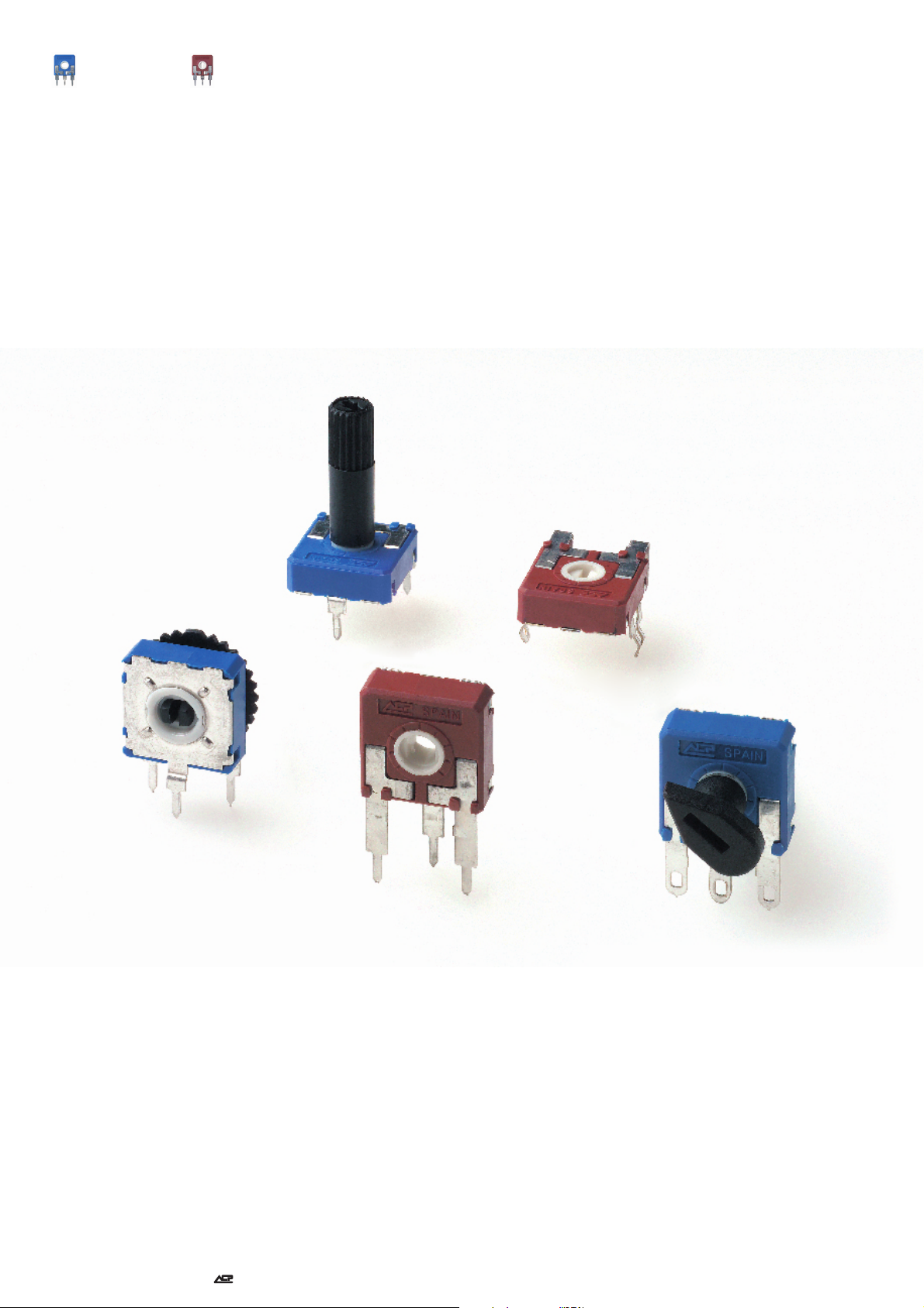
14mm carbon potentiometers with plastic housing and protection
type IP 5 (dust-proof).
CE14
14mm cermet potentiometers with plastic housing and protection
type IP 5 (dust-proof). Self-extinguishable according to UL 94 V-0.
Standard tapers available include linear, log and antilog. ACP can
also study special requests.
Terminals are manufactured in tinned brass to guarantee better
soldering and higher resistance to corrosion. They can be provided
straight or crimped (with “snap in”), recommended to hold the
potentiometer to the board prior to the soldering operation. SMD
confi guration can be available on request.
Thumbwheels and shafts can be provided either separately or
already inserted in the potentiometer.
ACP’s potentiometers can be adjusted from either side, both in the
horizontal and the vertical adjustment types. There is a guide on
the housing to simplify the manual adjusting operations.
Our potentiometers can be manufactured in a wide range of
possibilities regarding:
- Resistance value.
- Tolerance.
- Tapers / variation laws.
- Pitch.
- Positioning of the wiper (standard is at 50%).
- Housing and rotor color.
- Mechanical life.
- Pause effect (up to 38 detents available).
- Self-extinguishable plastic parts according to UL 94 V-0.
Standard taper is linear. Log, Antilog and other tapers are available
on request. Laser trimming equipment in-house, allowing for very
low tolerances.
Terminals are manufactured in tinned brass to guarantee better
soldering and higher resistance to corrosion. They can be provided
straight or crimped (with “snap in”), recommended to hold the
potentiometer to the board prior to the soldering operation. SMD
confi guration can be available on request.
Thumbwheels and shafts can be provided either separately or
already inserted in the potentiometer.
ACP’s potentiometers can be adjusted from either side, both in the
horizontal and the vertical adjustment types. There is a guide on
the housing to simplify the manual adjusting operations.
Our potentiometers can be manufactured in a wide range of
possibilities regarding:
- Resistance value.
- Tolerance.
- Tapers / variation laws.
- Pitch.
- Positioning of the wiper (the standard is at 50%).
- Housing and rotor color.
- Mechanical life.
- Pause effect (up to 38 detents available).
Applications
- Electronic appliances: white goods, brown goods, small household appliances
- Heating and air conditioning equipment and thermostats.
- Automotive: dimmers, climate controls, lighting regulation (position adjustment and sensing).
- Measurement and test equipment.
Applications
- Electronic appliances: white goods, brown goods, small house
hold appliances, boilers, water heaters, etc.
- Heating and air conditioning equipment and thermostats.
- Automotive: dimmers, climate controls, position sensors.
- Industrial electronic: multimeters, oscilloscopes, test equipment,
time relay.
www.acptechnologies.com
|
31
|
Page 3
CA14 CE14
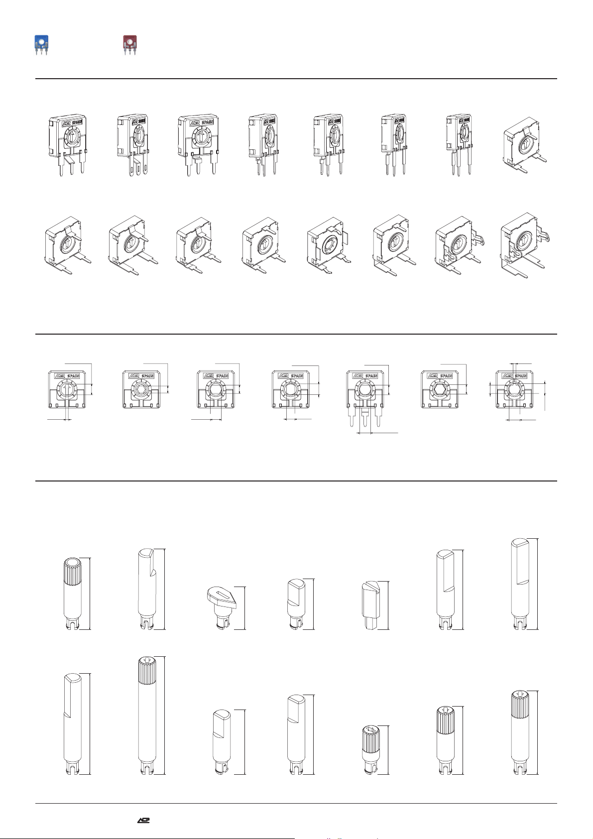
Models
All models shown here have the standard rotor for the 14mm series, the arrow (P). Models can be manufactured with any rotor listed on
the rotor menu. The color of the housing or rotor can also be modifi ed. SMD confi guration can be available on request.
CA14 H0
CE14 H0
CA14 VA12,5
CE14 VA12,5
CA14 HC0
CE14 HC0
CA14 VL12,5
CE14 VL12,5
CA14 H2,5
CE14 H2,5
CA14 VR12,5
CE14 VR12,5
CA14 H4
CE14 H4
CA14 V15
CE14 V15
CA14 H5
CE14 H5
CA14 V15…CFF
CE14 V15…CFF
CA14 HA5
CE14 HA5
CA14 V17,5
CE14 V17,5
CA14 HL5
CE14 HL5
CA14 VD7,5
CE14 VD7,5
Rotors
The rotor by default is the arrow (P). Accessories are designed for the N, Z and T rotors, unless otherwise stated.
1±0,1
4±0,05
2,6±0,05
4,05±0,05
3,08±0,05
4,05±0,05
3,08±0,05
3,6±0,05
4,08±0,05
3,55±0,05
MNP DEZT
Shafts
• CA14. Shafts are available in different colors. They can also be
provided in accordance with UL 94 V-0.
Potentiometers can be supplied with shafts already inserted in.
ACP can also study special shafts.
• CE14. Shafts provided in accordance with UL 94 V-0 are
available in different colors.
Potentiometers can be supplied with shafts already inserted in.
ACP can also study special shafts.
CA14 V12,5
CE14 V12,5
CA14 VD11
CE14 VD11
1,1±0,05
3,62±0,05
4,1±0,05
29,5
14008
38,25
29,5
14015 14042
45
14072 14073 14081
www.acptechnologies.com
32
|
|
13,4
24,5
14056
14084
18,5
29,75
17
14065
For the M rotor
18
14066 14067
14117 1425014187
Complete drawings can be found on pages 81-83
29,75
25,2
34,35
31,5
Page 4
Thumbwheels
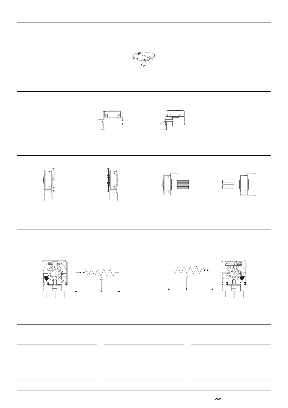
• CA14. This thumbwheel is available in different colors. It can also
be provided in accordance with UL 94 V-0.
Potentiometers can be supplied with thumbwheels already inserted
in. ACP can also study special requests for thumbwheels.
• CE14. This thumbwheel in accordance with UL 94 V-0 is avail-
able in different colors.
Potentiometers can be supplied with thumbwheels already inserted
in. ACP can also study special requests for thumbwheels.
14003
Terminals
By default, terminals are always straight for the 14mm size, as shown on the “models” menu.
ACP can provide crimped terminals (with “snap in”), to better hold the component to the board prior to soldering.
1,8
1
R1,5
1,5
0.9
SNP SNR
Adjustment possibilities
ACP’s potentiometers can be adjusted through either the front side (WT) or the collector side (WTI):
WTI
Collector side
WT
Front side
WTI
Collector side
WT
Front side
Potentiometers with cut track
The resistive element in this potentiometer has an area with very high resistive values, resulting in an open circuit. Recommended for
lighting regulation.
With cut at the beginning of the track CCW: Off-On.
With cut at the end of track- CW: On-Off. Others position available on request.
AB
C
CCW: Off-On CW: On-Off
Packaging
Bulk packaging: Potentiometers are fi rst bagged and then introduced in boxes:
Potentiometer model + Shaft or thumbwheel inserted Pieces per box (130 x 60 x 90)
- (only potentiometers)
H2,5 - H4 - H5 - HA5 - HL5 -HC0 - H0
V12,5 - VA12,5 - VL12,5 - V15 - V17,5* - VD11*
VD7,5 - VR12,5
14008, 14015, 14250, 14187, 14056, 14065
14066, 14067, 14072, 14073, 14081, 14084
14003, 14117, 14042
Tape and reel (T&R) packaging will be available for SMD confi gurations, on request.
Complete drawings can be found on pages 81-83
AB
C
200 (models with * : 150)
100
75
www.acptechnologies.com
|
33
|
Page 5
CA14 CE14
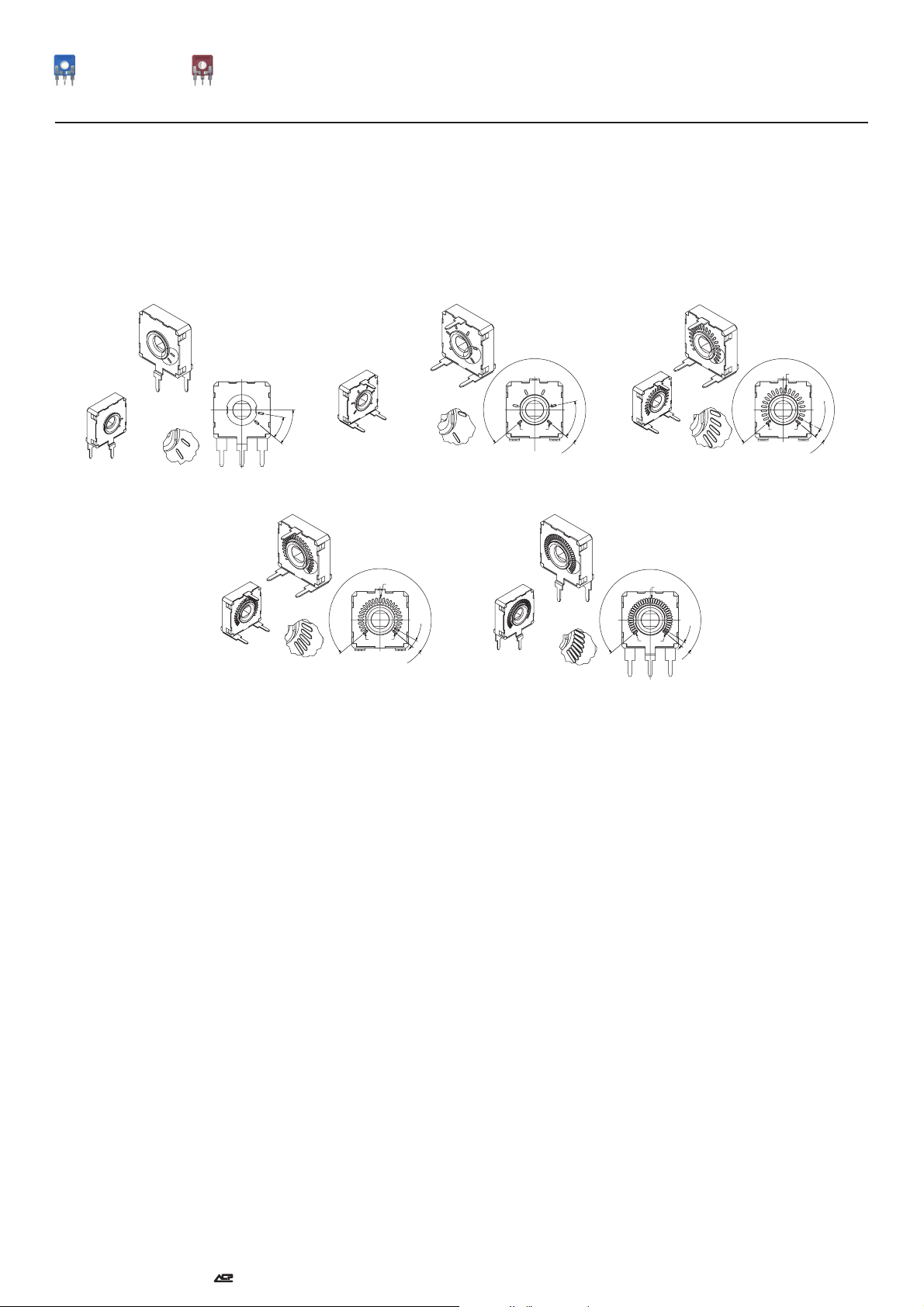
Potentiometers with detents
ACP’s “detent” (DT) feature is specially suitable for control applications. Our patented design has improved the performance of these
potentiometers:
- Longer mechanical life: 10.000 cycles.
- More stable electrical parameters.
- Improved reliability and Contact Resistance Variation (CRV).
- Narrower tolerances for detent positioning.
Detents can be lighter or stronger, or even a combination of both feelings. They can also be evenly distributed along the angle (standard)
or tailored to match customers’ request. They can also be combined with special tapers: constant value areas, different slopes, etc.
Examples:
A
DETAIL
DETAIL
30°
40°
2DT 22DT
A
14
10°
1
27
DETAIL
260°
6DT
A
52°
1
6
260°
A
DETAIL
DETAIL
19
7°
38
1
260°
27DT 38DT
A
11
12,38°
1
22
260°
www.acptechnologies.com
34
|
|
Page 6
CA14. Electric Specifi cations
CE14. Electric Specifi cations
These are standard features; other specifi cations can be studied on request.
Range of resistance values
Lin (A) 100Ω ≤ Rn ≤ 5MΩ
Log (B) Antilog (C) 1 KΩ … 2,2 MΩ
100Ω … 1MΩ ±20%
Tolerance
Special tolerances available on request
Out of range: Rn> 5MΩ: +50%, -30%
Variation laws
Residual resistance
Minimum value 2Ω
CRV - Contact Resistance Variation (dynamic) ≤3%Rn
CRV - Contact Resistance Variation (static) ≤5%Rn
Maximum power dissipation at 40º C.
Lin (A) 0,25W
No Lin (B, C) 0,13W
Maximum voltage at 40ºC
Lin (A) 250VDC
No Lin (B, C) 200VDC
Operating temperature -25°C … +70°C
Temperature coeffi cient
>10KΩ - 5MΩ Æ +200/ -500 ppm
Lin (A), Log (B), Antilog (C) ≤ 5*10
100Ω - 10KΩ Æ +200/ -300 ppm.
>1MΩ … 5MΩ ±30%
Lin (A), Log (B), Antilog (C)
Other tapers available on request
-3
*Rn
These are standard features; other specifi cations can always be studied on request.
Range of resistance values
Lin (A) 100Ω ≤ Rn ≤ 5MΩ
Log (B) and Antilog(C) 1KΩ … 2,2MΩ
100Ω … 1MΩ ±20%
Tolerance
Special tolerances available on request
Out of range: Rn> 5MΩ: +50%, -30%
Lin (A)
Variation laws Log (B), Antilog (C) and other
tapers available on request
Residual resistance
CRV - Contact Resistance Variation (dynamic) ≤3%Rn
CRV - Contact Resistance Variation (static) ≤5%Rn
Maximum power dissipation at 70º C.
Lin (A) 0,7W
Non Lin (B, C) See note 1
Maximum voltage at 40ºC
Lin (A) 250VDC
Non Lin (B, C) See note 1
Operating temperature -40°C … +125°C
Temperature coeffi cient
Note 1: Value depends on taper, please, inquire.
>1MΩ … 5MΩ ±30%
Lin (A) ≤ 2Ω
±100ppm.
CA14. Mechanical Specifi cations
Resistive element Carbon technology
Angle of rotation (mechanical) 265º ± 5º
Wiper position Middle position: 50% ± 15º
Angle of rotation (electrical) 245º ± 20º
Max. stop torque 10 Ncm
Max. push/pull on rotor 50 N
Wiper torque
(0,5 ... 3,5Ncm for pots. with detents)
Mechanical life
(10.000 cycles for pots. with detents)
< 2,5 Ncm
1000 cycles (more available on request)
CA14. Test
Test // Conditions // Typical variation of Nominal Resistance
Damp heat // 500 h. at 40°C and 95% RH // +5%; -2%
Thermal cycles // 16h at 85ºC, plus 2h at –25ºC // ±2,5%
CE14. Mechanical Specifi cations
Resistive element Cermet
Angle of rotation (mechanical) 265º ± 5º
Wiper position Middle position: 50% ± 15º
Angle of rotation (electrical) 245º ± 20º
Max. stop torque 10 Ncm
Max. push/pull on rotor 50 N
Wiper torque
(0,5 ... 3,5Ncm for pots. with detents)
Mechanical life
(10.000 cycles for pots. with detents)
< 2,5 Ncm
1000 cycles (more available on request)
CE14. Test
Test // Conditions // Typical variation of Nominal Resistance
Damp heat // 500 h. at 40°C and 95% RH // ±2%
Thermal cycles // 16h at 90ºC, plus 2h at –40ºC // ±2%
Load life // 1.000 h. at 40°C // +0%; -5%
Mechanical life // 1000 cycles at 10 c.p.m. and at 23°C ± 2°C // ±3%
Soldering effect // 2 seconds at 350°C // ±1%
Storage (3 years) // at 23°C ± 2°C // ±3%
For further information on tests, go to TESTS AND RELIABILITY on pages 10-11.
All specifi cations are given at 23°C ± 2°C and 50% ± 25% RH.
Load life // 1.000 h. at 70°C // ±2%
Mechanical life // 1000 cycles at 10 c.p.m. and at 23°C ± 2°C // ±2%
Soldering effect // 2 seconds at 350°C // ±1%
Storage (3 years) // at 23°C ± 2°C // ±1%
For further information on tests, go to TESTS AND RELIABILITY on pages 10-11.
www.acptechnologies.com
|
35
|
Page 7
CA14 CE14
• EXAMPLE: CA14NH2,5-10KA2020 10DT SNP PI WT14117-BA
• EXAMPLE: CE14NH2,5-10KA2020 10DT SNP PI WT14117-BAV0
HOW TO ORDER
Standard features
Series Rotor Model Packg
1 2 3 4 5 6 7 8
CA14/CE14
Standard confi guration
Dimensions: 14mm
Protection: • CA14: IP 5 (dust-proof)
• CE14:
Substrate: • CA14: Carbon technology
• CE14: Cermet
Color: • CA14: Blue housing with white rotor
• CE14: Brown housing with white rotor
Packaging: Bulk
Wiper position: at 50% ±15º
Terminals: Straight, without SNAP IN.
Marking: Resistive value marked on housing. Others on request
1 - Series
• CA14 • CE14
3 - Model and pitch
H0 HC0 H2,5 H4 H5 HA5 HL5 V12,5
VA12,5 VL12,5 VR12,5 VD11 VD7,5 V15 V17,5
N H2,5 -10K A 2020
IP 5 (dust-proof). Self-extinguishable, to meet UL 94 V-0
HSMD and VSMD models can be available on request.
Ohm value
Taper Tol Life
Extra features
Track Detents
9 10 11 12 13 14 15
10DT SNP PI
V15…CFF
Assembled accessory
Snap in
Housing Rotor Wiper Lin
Customized products
A drawing is requested to order a customized product. The code assigned will
include all special specifi cations.
Series, rotor, model and total resistive value are given before the special code:
CA14PH2,5 10K CODE C00111.
2 - Rotors
P (standard) M N Z D E T F
4 - Packaging
Through-hole SMD models
Bulk (blank)...
T&R (Tape and reel) (N.A.)
(1) If blank, bulk packaging is implied.
(2) N.A. - Not Available: Tape and Reel packaging is only available for SMD terminals.
Assembly
Ref # Color Flam.
16 17
WT 14117 -BA -V0
(1)
On request
(2)
On request
5 - Resistance value
Taper: Lin (A) Log (B), Antilog (C)
100 Ω / 100 1KΩ / 1K
Value Rn … / … … / …
5 MΩ / 5M 2,2 MΩ / 2M2
Other resistive values available on request.
7 - Tolerance
100 Ω ≤ Rn ≤ 1MΩ: ±20% 2020
1 MΩ ≤ Rn ≤ 5MΩ: ±30% 3030
For out of range values: Rn > 5MΩ, tol : +50% - 30% 5030
Special tolerances available: <5% ... 10%, etc.
9 - Cut track
At beginning of track, CCW: Off - On PCI
At end of track, CW: On - Off PCF
11 - Crimped terminals (SNAP IN)
SNAP IN P SNP
SNAP IN R SNR
6 - Resistance law / taper
Lin - Linear A
Log - Logarithmic B (on request for CE)
Antilog - Antilogarithmic C (on request for CE)
- Special tapers have codes assigned: CODE YXXXXX
Please, indicate terminal position when ordering a special taper.
8 - Operating life (cycles)
Standard (1000cycles) -(leave blank)
(1)
Long life: LV + the number of cycles. ex: LV10 for 10000 cycles
(1) Others on request.
10 - Detents (DT)
One detent at the beginning DTI
One detent at the end DTF
X number of detents XDT: 10DT
Detents readily available: 1, 2, 3, 4, 5, 6, 8, 9, 17, 22, 27, up to 38 -evenly distributed along 260º±3º.
Others on request.
12 - Housing color
• CA14: standard is blue
• CE14: standard is brown
With other colors -See color chart below-, for example, red CJ-color, ex.: CJ-RO
LVXX: ex: LV10
www.acptechnologies.com
36
|
|
Page 8

13 - Rotor color
Standard: white. With other colors: see color chart below RT-color; ex., red: RT-RO
14 - Wiper
Wiper position (Standard: 50% ± 15º) (leave blank)
Initial or CCW PI
Final or CW PF
Others: following clock positions; at 3hours: P3H PXH, ex: P3H
Wiper torque (Standard: <2,5Ncm) (leave blank)
Low torque (< 1.5Ncm) PGB
15 - Linearity
Independent linearity controlled & below x%, for example, 3%: LN3%
LNx%; ex: LN3%
Absolute linearity controlled & below x% LAx%
16 - Potentiometers with assembled accessories
Assembled from terminal side WT
Assembled from collector side WTI
Accessory Reference XXXXX
See list of shafts and thumbwheels available Example: 14117
Color of shaft or thumbwheel
Example, white: BA
-YY
17 - Flammability (according to UL 94 V-0)
• CA14: Not self-extinguishable (leave blank)
Self-extinguishable according to standard UL 94
(including all plastic parts of the potentiometer: rotor, housing and -V0
accessory. If only one part needs to be V0, please, inform)
• CE14: All accessories assembled with cermet potentiometers will
have the self-extinguishable property according to standard UL 94
-V0
For ordering spare accessories
Accessory reference - color- fl ammability. Ex. 14117-AZ-V0 is a blue self-extinguishable 14117 thumbwheel XXXX-YY-_ _
Color chart for rotor, housing and accessories
(1)
Black
NE
White BA
Neutral IN
Transparent TA
Red RO
Green VE
Yellow AM
Blue AZ
Grey GS
Brown MR
(1) Black is not an option for housings.
Specifi cations on this catalogue are for reference only; they are subject to change without notice.
www.acptechnologies.com
|
37
|
Page 9
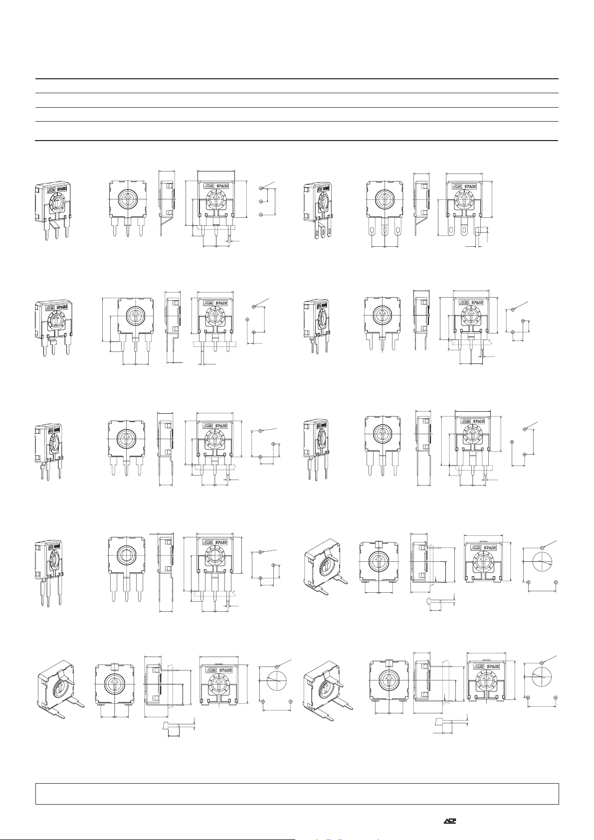
DRAWINGS CA14 // CE14
Tolerances 14 mm (in mm.):
<1
1...<10
10...
Model types. CA14 // CE14
CA14 H0 // CE14 H0
±0,1
±0,3
±0,5
CA14 HC0 // CE14 HC0
CA14 H2,5 // CE14 H2,5
17
10
4
CA14 H5 // CE14 H5
5 5
6
14
Ø1,3
5
14
17
10
4
1
5
5
10
5 5
6
14
14
14
2
1,2
CA14 H4 // CE14 H4
6
2,5
14
Ø1,3
14
1
10
2,5
6
16,6
14
Ø1,3
14
8,8
9,6
4
1
4,44,4
4,4
4
CA14 HA5 // CE14 HA5
6
5
14
Ø1,3
17
10
4
5 5
14
10
5
5
1
6
5
19,5
12,5
14
Ø1,3
14
4
5 5
1
10
5
CA14 HL5 // CE14 HL5
CA14 VA12,5 // CE14 VA12,5
5 5
Specifications on this catalogue are for reference only; they are subject to change without notice.
6
View A
CA14 V12,5 // CE14 V12,5
View A
6
7,5
A
7
4
12,5
1
14
Ø1,3
5
Ø7
14
7,5
10
14
Ø1,3
14
20,8
13,8
4
5
5 5
10
5
5
1
5 5
CA14 VL12,5 // CE14 VL12,5
6
7,5
8,5
4
12,5
14
14
1
Ø1,3
5
Ø7
7,5
10
5 5
6
A
10,5
View A
3,5
14
12,5
7,5
1
14
Ø1,3
5
Ø7
7,5
10
www.acptechnologies.com | 81
|
Page 10
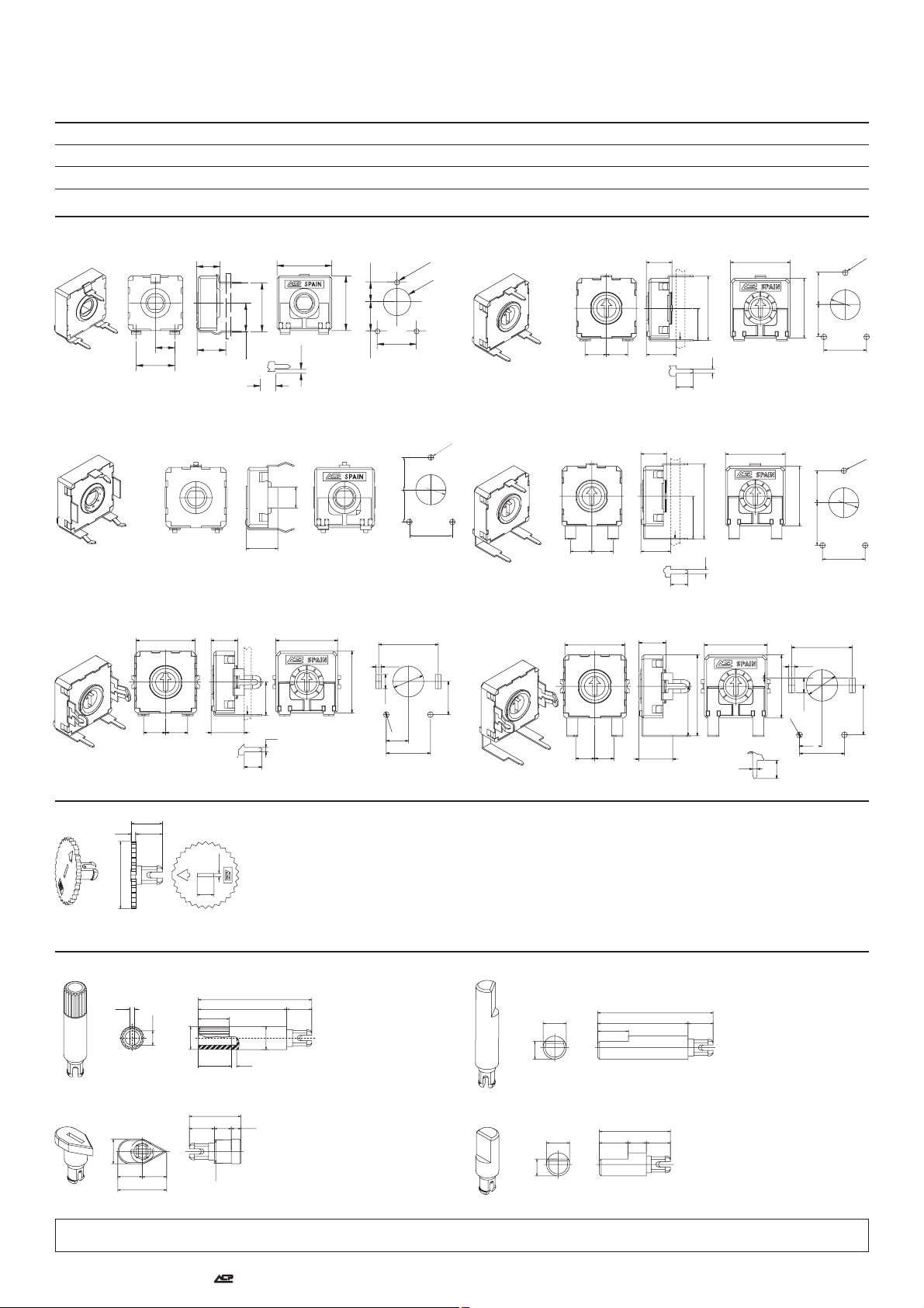
DRAWINGS CA14 // CE14
Tolerances 14 mm (in mm.):
<1
1...<10
10...
Model types. CA14 // CE14
CA14 VR12,5 // CE14 VR12,5
±0,1
±0,3
±0,5
CA14 V15 // CE14 V15
6
5
10
7
CA14 V15...CFF // CE14 V15...CFF
CA14 VD7,5 // CE14 VD7,5
13,5
55
6
7,5
View A
Thumbwheels. CA14 // CE14
14003
1,1 6,4
7,5
7.5
12.5
View A
6
15
7,5
A
7
4
14
1
4
57.5
Ø1.3
Ø7
14
10
5 5
14
14
1
Ø1,3
7,5
Ø7
7,5
10
CA14 V17,5 // CE14 V17,5
Ø1,3
7,5
6
7
Ø7
7,5
10
5 5
6
7
View A
14
17,5
10
A
1
4
14
Ø1,3
7,5
Ø7
10
10
CA14 VD11 // CE14 VD11
14
14
7,5
A
1
4
13,5
1,3
Ø7
3,2
Ø
1,3
5
7,5
10
13,5
4,4 4,4
6
7,5
14
0
18
11
1
4
13,5
1,3
7
Ø
14
3,2
Ø1,3
5
11
10
0,8
Ø16
Ø4
Shafts. CA14 // CE14
14008 14015
8
8,6
13,4
29,5
23
1,4
4,4
2,5
Ø6
6,5
Ø6
14056
14042
6,35
1,1
= =
3,8
Ø5,9
6,5
12,7
Specifications on this catalogue are for reference only; they are subject to change without notice.
82 | www.acptechnologies.com
|
29.5
6
4,6
6
4,4
23.25
8
18,5
4,75
7,5
6.25
6,25
Page 11
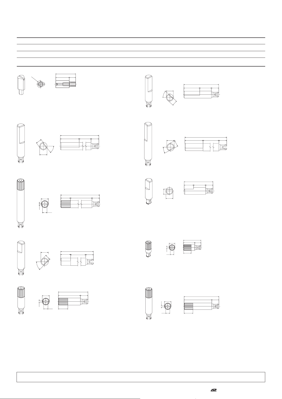
DRAWINGS CA14 // CE14
Tolerances 14 mm (in mm.):
<1
1...<10
10...
Shafts. CA14 // CE14
14065
R3,175
±0,1
±0,3
±0,5
11,5
17
5,5
14066
29,75
6
42,5°
13,5
4,5
6,25
10
14067
14073
14084
14072
34,35
4,6
54∞
6
15,2 12,9 6,25
6
5
28∞
38,25
14,5 17,5
6,25
14081
24,5
10,25 6,25
8
45
30,75 6,25
Ø6
1,2
3,7
8
14117
6
4,6
45∞
29,75
15,5
6,25
8
4,6
6
18,2
11,7
Ø6
1,2
3,7
6,5
8
14187
14250
25,2
Ø6
1,2
3,7
18,7
8
6,5
Ø6
1,2
3,7
31,5
25
8
6,5
Specifications on this catalogue are for reference only; they are subject to change without notice.
www.acptechnologies.com | 83
|
 Loading...