

Page 1
Wet Stove Installation Guide
Wet Stove Installation Guide
May 2015
BS EN 13240:2001 +A2:2004 CE
BK555 Rev09
Page 2

Wet Stove Installation Guide
Arada Ltd
May 2015
Please carefully read through the entirety of this installation guide before
commencing installation. Should you have any questions about our stoves
that are not covered in this manual, please contact the Arada retailer in
your area, or call our technical support department on 44 (0)1297 35998.
You should retain these instructions for future reference.
Arada has a policy of continuous product development and therefore
we reserve the right to amend specications without prior notice. Due to
printing cycles, items or options may be described before they are generally
available or after they have ceased. Please check with your retailer or
dealer if you are unsure about any aspect of your stove, its installation or
correct use.
Page 3

Wet Stove Installation Guide
Contents
1 Warnings 1
2 Health and Safety 1
3 Installation Requirements 2
3.1 Hearths and Recesses . . . . . . . . . . . . . . . . . . . . . 2
3.2 Combustible Materials . . . . . . . . . . . . . . . . . . . . . 3
3.3 Air for Combustion . . . . . . . . . . . . . . . . . . . . . . 3
4 Flue and Chimneys 5
5 Installing the Stove 7
5.1 Removing the door . . . . . . . . . . . . . . . . . . . . . . . 7
5.2 Assembling the grate bars . . . . . . . . . . . . . . . . . . . 7
5.3 Fitting the spigot outlet to the stove . . . . . . . . . . . . . 8
5.4 Connecting the spigot outlet to the ue system . . . . . . 8
5.5 Fire Bed Surrounds . . . . . . . . . . . . . . . . . . . . . . . 9
5.6 Flue Exhaust Diversion System (FEDS) . . . . . . . . . . . . 9
5.7 Sealing the back and base of inset stoves to a re surround 10
5.8 Adjusting the self leveling feet (if applicable) . . . . . . . . 10
6 Connecting the boiler to your heating circuit 10
6.1 Safety cooling loop (for Stratford dedicated wood boilers) . 10
6.2 Integral Boilers . . . . . . . . . . . . . . . . . . . . . . . . . 12
6.3 Water Connections . . . . . . . . . . . . . . . . . . . . . . . 12
6.4 Safety Vent Circuit . . . . . . . . . . . . . . . . . . . . . . . 13
6.5 Thermostat and damper pressure checks . . . . . . . . . . 14
6.5.1 To remove the thermostat . . . . . . . . . . . . . . 14
6.5.2 Calibrating . . . . . . . . . . . . . . . . . . . . . . . 15
7 Maintenance 16
7.1 Removal of ash around the damper and thermostat . . . . 16
8 Final check list and commissioning the stove 19
BK555 Rev09
Page 4

Wet Stove Installation Guide
1 Warnings
It is a legal requirement that the installation of all new or replacement,
wood or solid fuel heating appliances obtain Building Control approval from
your local authority. This can be done by using a qualied heating engineer,
aliated to a government approved competent persons scheme such as
operated by HETAS.
If in doubt, contact HETAS Limited, telephone: 0845 634 5626 or visit
www.hetas.co.uk. You can also consult your local buildings inspector /
controller.
All local regulations, including those referring to National and European
standards, need to be complied with when installing the appliance.
This stove should not be installed into a chimney that serves any other
heating appliance.
Any manufacturer’s instructions must not be taken as overriding
statutory requirements.
Arada Ltd will not be responsible for any consequential or incidental loss
or injury however caused.
Any further warnings in this document will be marked out
in a box such as this one. Ignoring the warnings could lead
to damage/injury to persons and/or property.
2 Health and Safety
Before any installation work is undertaken consideration must be given
to the Health and Safety at Work Act 1974. Safe working practices should
be followed at all times.
Please consult health and safety guidelines for advice on handling heavy
and/or large items.
BK555 Rev09 1
Page 5

Wet Stove Installation Guide
During installation ensure that adequate precautions are taken to avoid
unnecessary risk to yourself or any householder.
The danger from the caustic nature of re cement, should be avoided
by using these accepted methods: Wear gloves when handling re cement.
Wear goggles when chiseling or looking up chimneys.
This stove contains no asbestos. If there is a possibility of disturbing
any asbestos in the course of the installation then please seek specialist
guidance and use appropriate protective equipment.
3 Installation Requirements
3.1 Hearths and Recesses
The stove should be installed on a surface with adequate load bearing
capacity. If the existing construction does not meet this prerequisite,
suitable measures (e.g. load distributing plate) should be taken to achieve
it. Please pay particular attention when examining existing building work
for suitability to meet the following requirements.
When installing an inset stove, hearths should have a suciently at
surface to allow a good seal to the stove body to be created during its
installation. Stonework, uneven bricks etc., may need further work to
ensure that this can be achieved. Any voids behind an inset stove should
be lled with vermiculite or similar.
The stove should be installed on a non-combustible surface not less
then 125mm thick (conforming to Building Regulations unless otherwise
specied) of suitable load bearing capacity and heat resistance. Allowances
should be made for the expansion and contraction of any materials which
are tted up to and near the appliance.
Dimensions of the constructional hearth for all stoves should project at
least 500mm forward of the front of the appliance and 150mm at the sides.
The surface of the hearth should be free of combustible materials. The
superimposed hearth for all installations should project at least 225mm
forward from the front of the appliance and 150mm either side of the
edge of the appliance.
BK555 Rev09 2
Page 6

Wet Stove Installation Guide
In most buildings with solid concrete or stone oors, the requirement will
be met by the oor itself, but mark the hearth to ensure oor coverings
are kept well away or use dierent levels to mark the hearth perimeter.
Please be aware that hot air can cause staining above the re in a similar
fashion to walls above radiators. To help prevent this and cracking we
recommend that any plaster above the re should be tted with reinforcing
expanding mesh for at least 220mm above, and the full width of the re.
You should also use a suitably heat resistant plaster which should be
allowed sucient time to fully dry before using the stove or cracking is
likely to occur.
3.2 Combustible Materials
Please view the product sheet which accompanied your stove for specic
minimum distances to combustible measurements.
Ideally, adjacent walls should be of suitable non-combustible
construction, preferably brickwork.
In large replaces take care that any supporting beam is protected by
a 13mm sheet of heat resistant re board spaced 12mm o the surface
with strips of non-combustible material. Make sure that there is a gap
between an un-insulated ue system and any combustible material. This
gap must be at least 3X the outside diameter of the ue pipe, or 1.5X
the ue diameter to non combustible surfaces. Please consult the ue
manufacturers specication for insulated ues.
3.3 Air for Combustion
All stoves require ventilation to burn safely and correctly. There are a
number of requirements that need to be met when installing a stove, for
example, allowing for the permeability of the house (air permeability is the
general seepage of air into the house via air vents, doors and windows
etc.)
There must always be a permanent means of providing air for
combustion into the room in which the stove is installed. Air starvation
will result in poor ue draw and may cause smoke to leak into the room.
BK555 Rev09 3
Page 7

Wet Stove Installation Guide
For all installations it is recommended that a permanent vent with a
total free area of at least 550mm2for every kW above 5kW should be
connected directly to the outside air. Installations in properties built after
2008 should have their vent increased by a further 330mm2for each of
the the rst 5kW. Alternatively this air can be supplied through an external
wall of an adjacent room, which itself has to be connected to the room the
appliance is installed by a permanent vent of the same size.
Note: If the appliance is tted with a draught stabiliser (or if one is tted
to the ue pipe or chimney in the same room as the appliance) then the
permanent air entry opening (or openings) should be increased by 300mm
2
for each kW of rated output up to 5kW and an additional 850mm2for each
kW output over 5kW.
If there is more than one appliance in the property then each appliance
must be supplied with adequate combustion air so that all appliances can
be lit simultaneously.
The positioning of any air vent must be so that it cannot be liable to
blockage or obstruction. Ideally it should also be positioned where it is
unlikely to cause a cold draught. It should not be positioned in the replace
recess.
The tting of an extractor fan in the same room as the
stove, or an adjacent room is not permitted. A spillage test
will be required to determine how any extractor fans may
aect the required size of ventilation requirements.
For more detailed guidelines on required ventilation sizes please refer
to the HETAS Guide which can be found on the HETAS website.
If you plan to use an external air supply on a suitable stove, and have
bought the appropriate Arada External Air Supply Kit, please refer to the
instructions included with the kit on how to install it.
The accompanying stove technical product sheet states whether or not
your appliance is compatible with a Direct Air Supply Kit.
BK555 Rev09 4
Page 8

Wet Stove Installation Guide
4 Flue and Chimneys
The stove must be connected to a suitable and ecient ue so that
products of combustion (fumes) from the stove are expelled to the outside
air. Please remember that chimney draught is dependent on four main
factors :
• Flue gas temperature
• Flue height
• Flue size
• Flue terminal
To ensure a good up draught it is important that the ue gases are kept
warm and that the ue size suits the stove. The termination of the outlet
at the top of the ue also needs to comply with Building Regulations. The
minimum eective height of the ue must be at least 4.5 metres from the
top of the stove to the top of the ue outlet. When warm the ue draught
should be between 0.1 to 0.2 mb.
The draw of a chimney / ue can vary in dierent weather conditions
and the customer should be made aware of this.
Failure to correct an over-drawing ue will invalidate the warranty.
A chimney may comply with regulations but could still be subject to down
draught and similar problems. A chimney terminating above the ridge level
is generally less likely to suer such problems.
If a new chimney is being provided it should fully comply with the relevant
Building Regulations that specify the requirements for solid fuel burning
installations. Suitable types of chimney include the following :
• Masonry Chimney : Built with clay or concrete liners, or a chimney
block system meeting Building Regulations. These types of chimneys
should be installed in accordance with the Building Regulations and
BS EN 15287-1:2007.
BK555 Rev09 5
Page 9

Wet Stove Installation Guide
• Factory Made Insulated Chimney : Complying with BS 4543:Part 2
(often called Class 1 prefabricated metal chimney). These types of
chimneys should be installed in accordance with Building Regulations
and BS EN 15287-1:2007.
Due to the gradual introduction of European Chimney Standards
chimneys will be specied according to their performance designation as
dened in BS EN 1443 that covers the General Requirements for chimneys.
The minimum performance designation required for use with solid fuel
burning stoves is T600 N2 S D3.
The ue and chimney installation must be carefully checked by a
competent person before tting the stove to ensure it is suitable and will
work safely.
If the chimney is old (i.e: built of brick or stone without a liner) or being
opened up for reuse additional checks and smoke testing as described in
Appendix E of the Approved Document J 2010 Edition should also be carried
out to ensure the ue and chimney are in good operating condition.
Check the existing ue is in good condition with suitable access for
collection and removal of debris.
It is also important that suitable ue pipe (recommended at least
600mm in length) complying with the Building Regulations is used to
connect the stove to the ue in the chimney. Suitable access should be
provided into the ue for regular inspection and sweeping of the ue ways.
The installer should comply with Building Regulations requirements in
respect of providing a Notice Plate giving details on the chimney, ue lining,
hearth and replace installation.
Chimneys should be as straight as possible. Horizontal runs should be
avoided except where the rear outlet of the appliance is used, in which case
the horizontal section should not exceed 150mm in length. If necessary
a combination of 45◦and 90◦bends can be used as long as the sum of
their angles is not greater then 180◦in total. i.e four 45◦bends, or two
45◦and a 90◦bend.
BK555 Rev09 6
Page 10

Wet Stove Installation Guide
If the stove appears to be working hard but produces very little output
to the room it is likely that excess draw is present in the chimney, and that
heat is being sucked out of the appliance and up the chimney. If this is
the case we recommend the tting of a draught stabiliser in preference to
a ue damper, in the interest of safety and eciency.
5 Installing the Stove
To make the stove easier to manoeuvre (thus safer) we recommend you
remove the following parts which can then be retted when the stove is in
its nal position:
• Grate Bars
• Door (To help prevent the glass from breaking)
• Operating Tool
• Ash pan
• Flue Exhaust (Excluding the EB25HE)
5.1 Removing the door
Open the door so that itâs perpendicular to the stove body and then
carefully lift the stove door upwards of its hinges. To replace the door
reverse the instructions above.
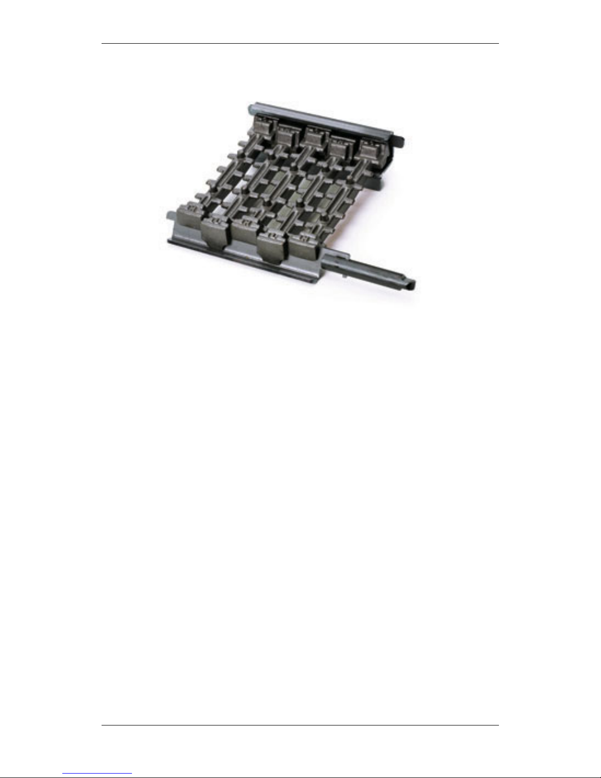
5.2 Assembling the grate bars
In your stove the grate system comprises of a series of cast iron grate
bars, seated on a pair of combs. All bars in the grate are identical.
The bars should be seated with every other bar rotated 180 degrees,
so the ends marked ’H’ and ’L’ alternate on each comb. When assembling
the grate, t bars to the low sections of the comb rst by seating the
ends marked ’L’ onto the low part of the comb, whilst the ends marked ’H’
should then be seated on the high sections.
BK555 Rev09 7
Page 11
Wet Stove Installation Guide
Figure 1: Grate Bars shown seated on their comb outside the stove.
5.3 Fitting the spigot outlet to the stove
With the exception of the Stratford Ecoboiler 7, the ue outlet spigot is
found packed inside the appliance. The hot plate is supplied tted to the
top opening and is removed by turning clockwise.
Smear a very thin layer of re cement on the mating faces of the ue
outlet and the hot plate. Fit the outlet to the appliance in the desired
position.
5.4 Connecting the spigot outlet to the ue system
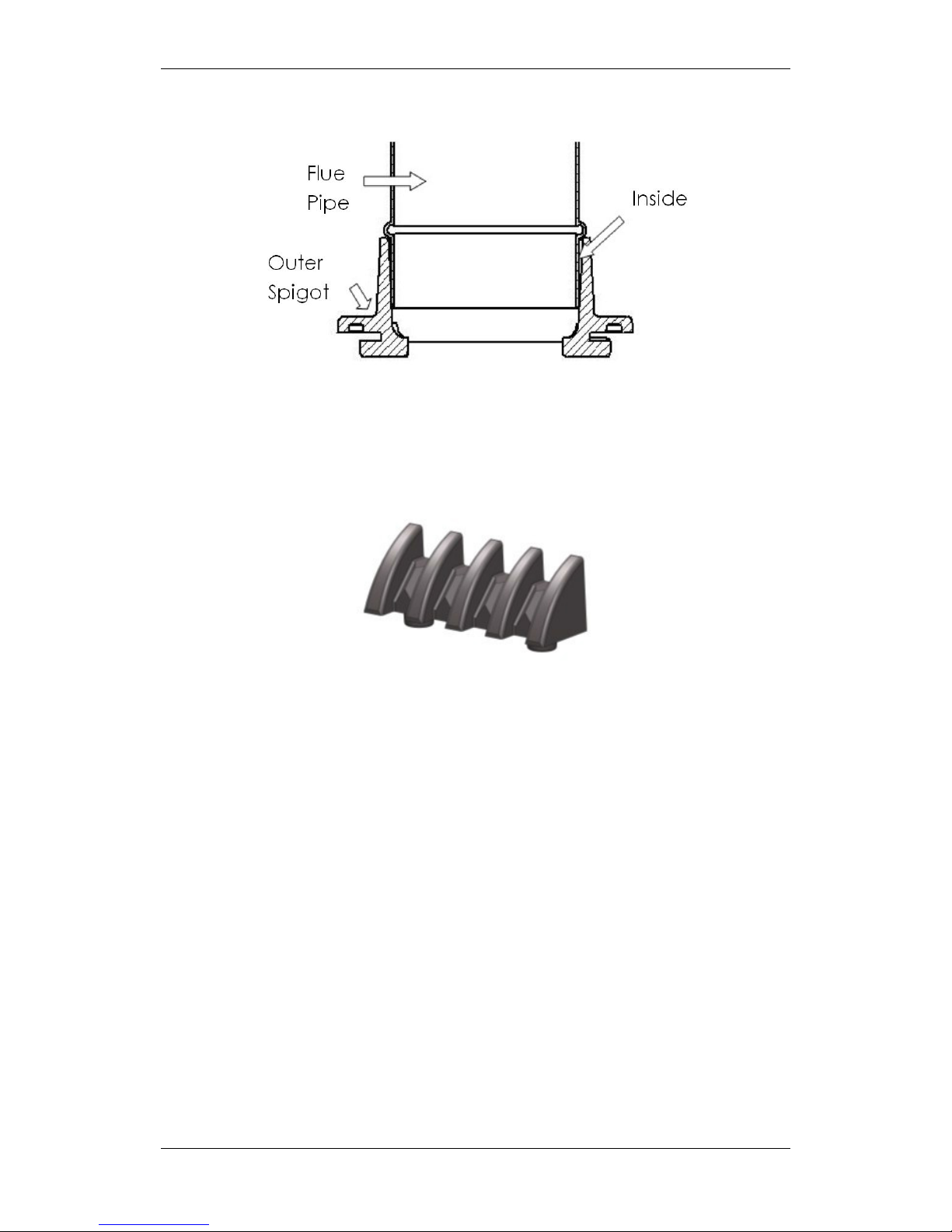
The ue pipe must be tted inside the outlet spigot as shown in Figure
2 on the following page. Failure to do so could result in the spillage of
condensation running down the ue.
Fire cement should be used to create an airtight seal between the ue
and spigot.
BK555 Rev09 8
Page 12
Wet Stove Installation Guide
Figure 2: Fitting the ue pipe inside the spigot collar.
5.5 Fire Bed Surrounds
Cast re bed surrounds are supplied with the boiler stove and should
be tted into the retaining holes in the rear grate bar support.
5.6 Flue Exhaust Diversion System (FEDS)
Please note that the following is not applicable to the EB25HE which features
an alternative system.
The inner section of the FEDS is welded in place during manufacture.
The outer FEDS is tted at the factory but may become dislodged during
transit. The rear end of the outer FEDS sits on retaining lugs as illustrated
below. If you need to remove the FEDS hold the bottom of it with both
hands, palms on the bottom sloping face. Push up rmly to release the
FEDS from the retaining lugs. It may require a swift knock upwards with
the palm of your hand to release it.
BK555 Rev09 9
Page 13

Wet Stove Installation Guide
5.7 Sealing the back and base of inset stoves to a re
surround
In order for the stove to operate correctly and at maximum eciency
it is necessary to achieve a good seal between the back face of the stove
convector section, the stove back base sections and the decorative re
surround and hearth.
This should be achieved using re cement. Any void surrounding an
inset stove when installed should be lled with re cement in the interest
of safety and ecacy.
5.8 Adjusting the self leveling feet (if applicable)
Adjustment is as follows:
• Position the stove on the hearth into its nal resting place.
• On the rear leg of the stove, loosen the pozi screw, and rotate the
inner ’cam’ shaped leveling foot until this touches the hearth.
• Re-tighten the pozi screw. Check the stove is level with a spirit level.
• Repeat for the other rear leg.
6 Connecting the boiler to your heating circuit
6.1 Safety cooling loop (for Stratford dedicated wood
boilers)
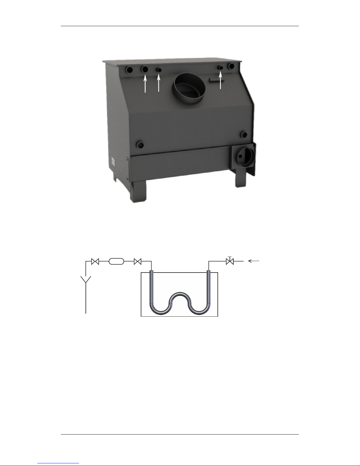
Your stove features three extra connections as shown below. These
should be used if you choose to congure your stove installation to work
with a cooling loop.
Please seek specialist advice when using these connections. A
suggested conguration is shown in gure 4 on the next page.
BK555 Rev09 10
Page 14
Wet Stove Installation Guide
Figure 3: Cooling loop outlets.
Inlet isolation
valve
Stove
Integral 22mm
cooling loop
Outlet isolation
valve
Temp. operated
safety valve*
Filter
Strainer
Flushed cooling loop
water to drain
or soak away
Cold water supply.
Ideally 10 -15˚
Mains pressure (2-4 bar)
* Watts STS 95°C Thermal Safety
Valve or equivalent
Figure 4: Cooling loop connections.
BK555 Rev09 11
Page 15

Wet Stove Installation Guide
6.2 Integral Boilers
Integral boilers should only be connected with the ow and return
connections of any circuit on opposite sides of the appliance (cross
owed) and to an indirect hot water tank / system with Fernox or other
similar corrosion inhibitor to prevent both corrosion and the formation of
limescale.
All Arada Boiler Stoves must be installed in an indirect
vented (also known as open vented) central heating system
Connecting pipes should be screwed to a maximum depth of 19mm for
the face of the tapping boss (1" BSP, parallel).
Remember to incorporate a drainage plug / tap at the lowest point of
the circuit to facilitate draining and ushing.
If a pipe-stat is not tted to control the radiator circulation pump then
cold water corrosion may occur.
6.3 Water Connections
To connect the indirect hot water cylinder to the stove use 28mm copper
pipes. Ensure that the pipes rise continuously to the cylinder.
Ensure that runs are not too long (i.e. 6 metre maximum each for ow
and return). Install the cylinder above the level of the re and as close to it
as possible. Within reason the higher the cylinder the faster the circulation.
Ensure no valves are present in the pipes.
In addition to providing hot water the primary circuit is essential in
providing a ’heat leak’ radiator to absorb excessive heat produced in the
event of a circulating pump shutting down.
Heat is produced in varying quantities while the stove is alight and care
must be taken to ensure that eective circulation can occur around the
primary circuit to carry the heat away thus preventing boiling. The heat
output of any radiator installed as a ’heat leak’ should not be less than 10
percent of the rated output of the appliance to which it is connected. It
BK555 Rev09 12
Page 16
Wet Stove Installation Guide
should not be tted with a control valve as it should never be turned o or
down. The hot water cylinder must be indirect with a minimum capacity
of 110 litres conforming to BS 1566 part 1.
A radiator of approximately 2m2surface area should be connected to
the primary circuit.
6.4 Safety Vent Circuit
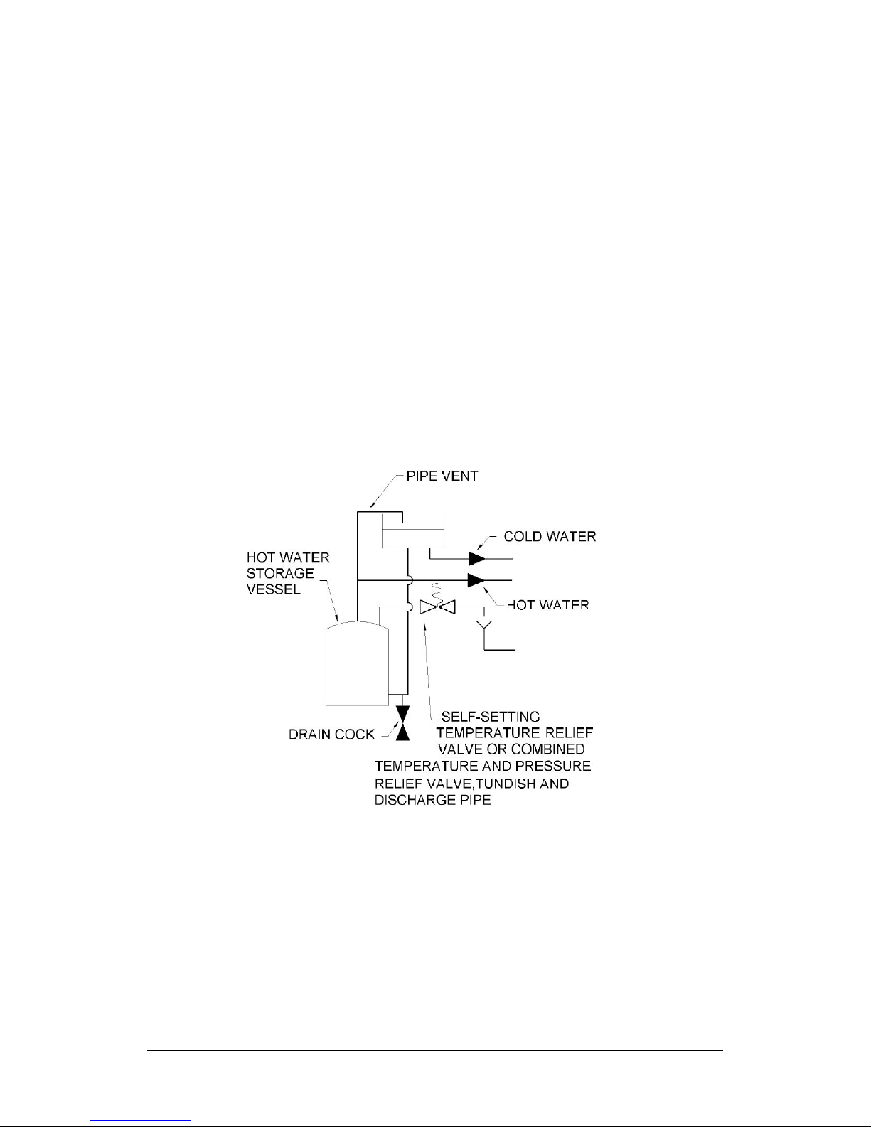
This circuit (shown in gure 5) consists of a cold feed pipe, a separate
expansion pipe and expansion tank. The possibility that water in the stove
boiler may boil can never be completely ruled out, and it is therefore vital
to ensure that cold water can be provided to the boiler and steam vented
from it at all times.
Figure 5: Safety Vent Circuit.
The use of an expansion tank is important. This should have a capacity
of at least 7 percent of the systems total water capacity. The cold water
feed pipe should be at least 22mm in diameter.
BK555 Rev09 13
Page 17

Wet Stove Installation Guide
There must not be any shut-o valves in the circuit. Pipes should be run
so as to avoid air locks. A safety valve should be tted into the expansion
pipe close to the boiler. The expansion pipe should not be branched o
from the cold water feed pipe to ensure that it cannot be blocked by any
sediment matter originating from the expansion tank.
It is often possible and good practice to utilise the primary ow and
return as part of the safety circuit. The ball valve and overow pipe (28mm
diameter) from the expansion tank should be copper. All pipes in unheated
spaces should be lagged.
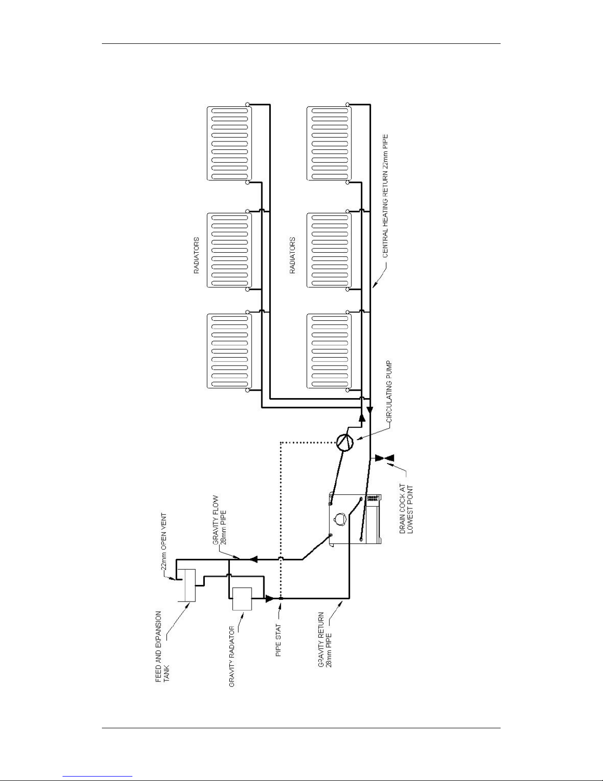
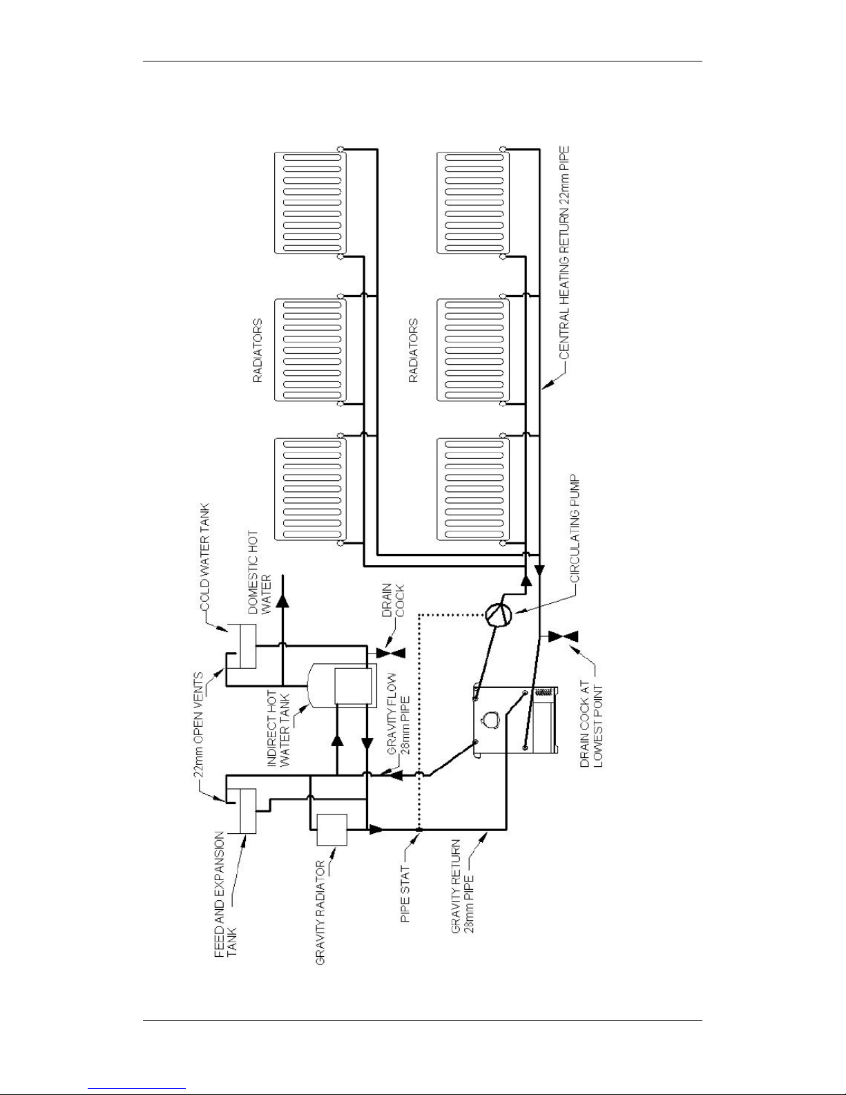
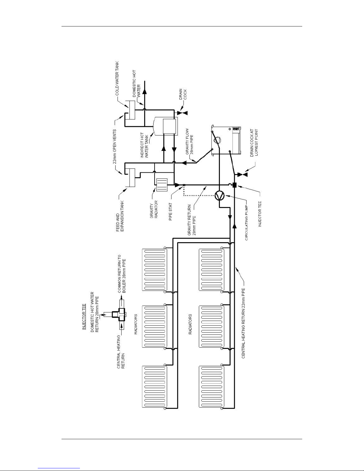
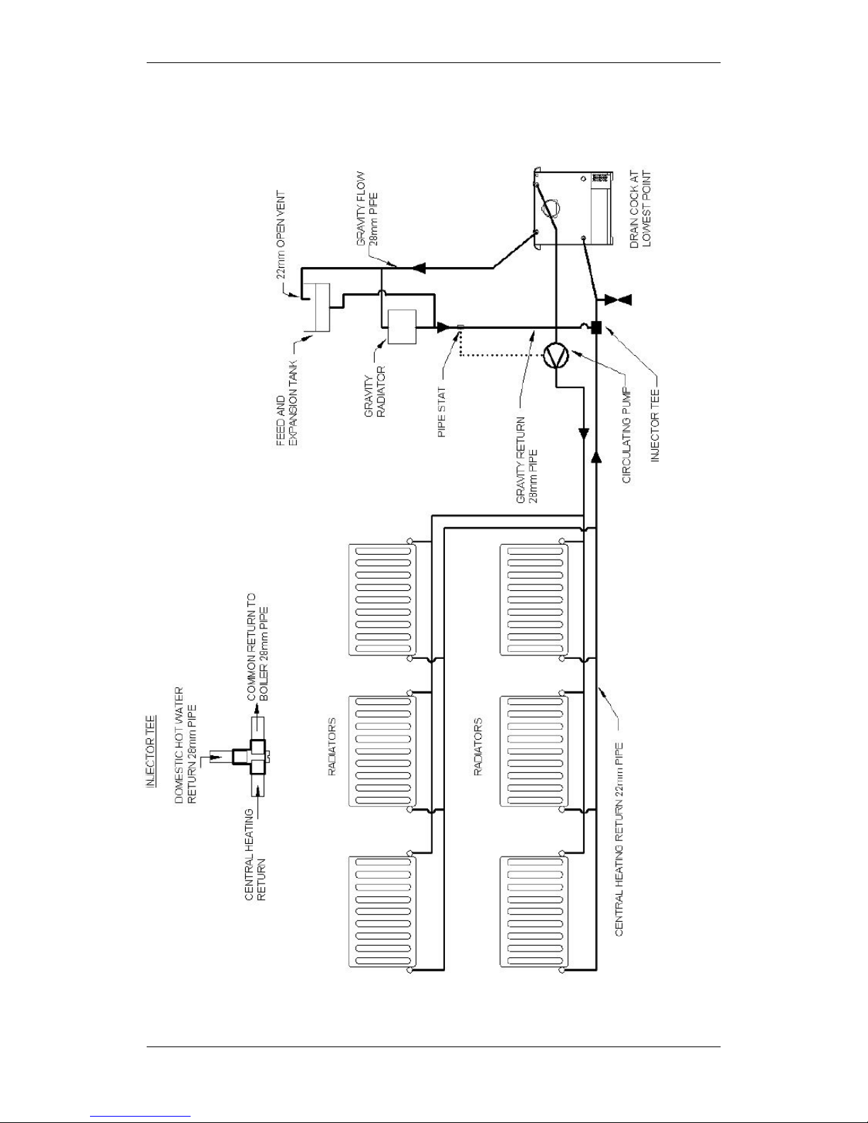
Various examples can be seen on page 21.
With solid fuel appliances, it is not practical to provide a suciently rapid
reaction for shutting down the fuel in the event of a sudden rise in water
temperature. A temperature valve, or preferably, a combined temperature
and pressure relief valve should be installed to operate in the event of high
water temperature occurring.
6.5 Thermostat and damper pressure checks
The thermostat has been tted and set correctly during the
manufacture. However it is advisable to check the cold setting prior to
lighting the re for the rst time.
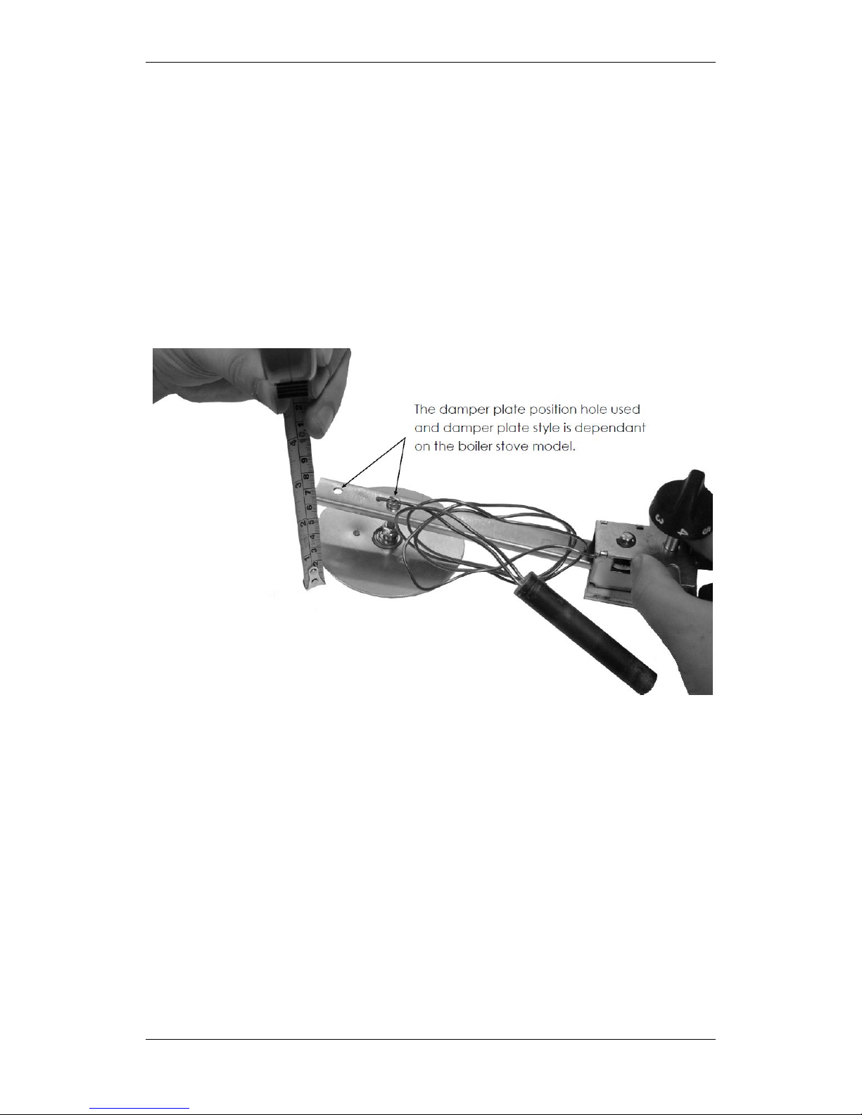
With the control knob turned fully clockwise (past No.5) the circular
damper plate should have a gap of approximately 29mm between the
damper edge and the stove inner body face when measured at the furthest
point from the control knob and in line with the actuation shaft. Take care
to measure this gap parallel to the actuation arm centre line.
If this is not the case then please follow the steps below to correct it.
6.5.1 To remove the thermostat
• Pull the thermostat knob o the shaft.
• Remove the access cover plate using a No.2 Pozi screw driver and
then remove the M5 screw.
BK555 Rev09 14
Page 18
Wet Stove Installation Guide
• Now remove the two M5 screws securing the thermostat to the stove
body. The thermostat should now be free and you will be able to
carefully remove it from the stove body.
• On the rear of the stove remove the thermostat sensor from its
pocket and push this carefully through the hole in corner cut-out of
the stove. (Take care not to kink the copper tubing.)
6.5.2 Calibrating
Figure 6: Checking damper ap distance.
With the thermostat removed, replace the control knob.
Rotate the control knob fully clockwise (as viewed with the damper shaft
to your left) until you reach the end of possible travel.
Place the thermostat on a at surface with the base of the mechanism
body on a small piece of 8mm thick MDF or similar wood.
BK555 Rev09 15
Page 19

Wet Stove Installation Guide
Now measure (as show in Figure 6 on the preceding page) the high end
of the damper plate between the bench and the top edge of the damper,
(the edge furthest from the control knob). This should be 29mm +/- 1mm,
if not adjust as follows:
• Slacken o the locking nut against the damper either in or out as
required.
• Check the distance at the high end of the damper plate again.
• Once set correctly re-lock the locking nut.
• Check the distance is still correct.
Once the correct distance is achieved please ret the damper ap
and thermostat by following the reverse of ’To remove the thermostatâİ
on 6.5.1 on page 14 and check once again that the correct distance is
maintained.
7 Maintenance
7.1 Removal of ash around the damper and thermostat
Regular checking and removal of ash from around the damper ap area,
inner left landing cavity and thermostat housing is necessary to ensure
correct operation.
To remove ash from around damper ap:
• Make sure the stove is unlit and cold.
• Remove the thermostat access cover as detailed on 6.5.1 on page 14.
• Carefully clean away any cold ash from the thermostat mechanism
and housing cavity using a vacuum cleaner.
• Ret the access cover.
BK555 Rev09 16
Page 20

Wet Stove Installation Guide
To remove ash from the inner left landing cavity:
• Make sure the stove is unlit and cold.
• Open the re door and remove the ash pan.
• Clean the under grate area carefully with a vacuum cleaner.
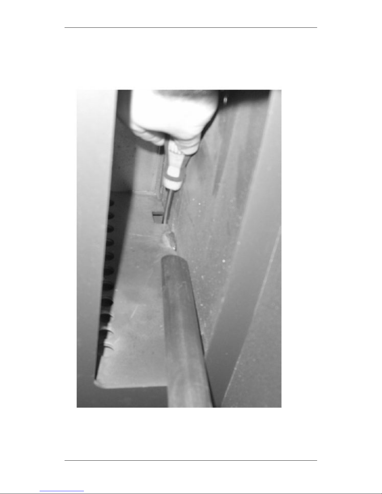
• Insert a small screwdriver or thin piece of wire into the slot at the
bottom of the inner left landing and loosen the ash build up between
the inner landing and damper mating face.
• Vacuum away any loose material.
• Repeat this until all ash is removed.
BK555 Rev09 17
Page 21
Wet Stove Installation Guide
Figure 7: Removing ash from left hand landing cavity.
BK555 Rev09 18
Page 22

Wet Stove Installation Guide
8 Final check list and commissioning the stove
Before handing over the installation to the customer it is a requirement
under Document J (of the Building Regulations for England Wales) that
the appliance is lit and the functioning of the chimney system is checked
for satisfactory operation. The functioning of the hot water and heating
system should also be fully checked.
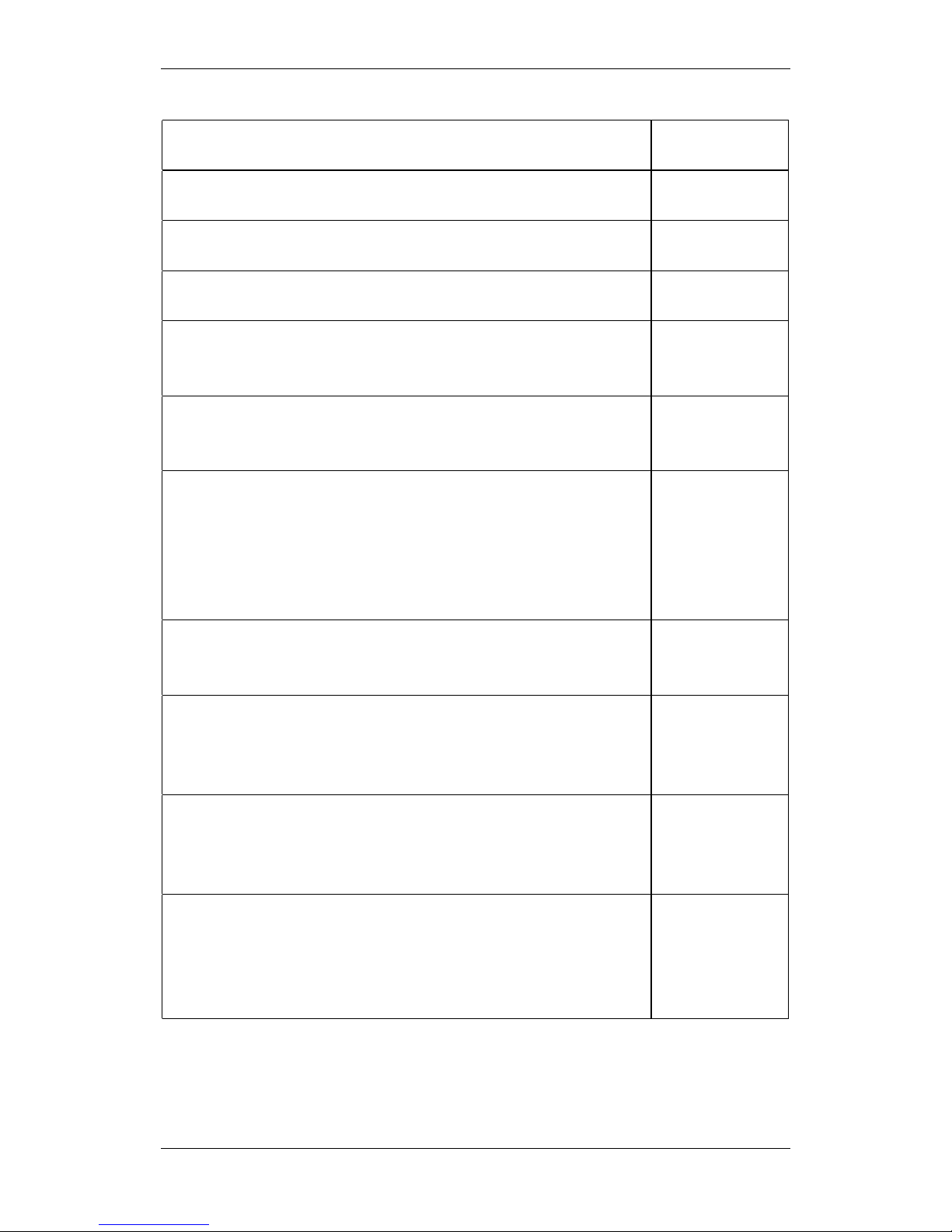
Please record the checks in the table below:
BK555 Rev09 19
Page 23
Wet Stove Installation Guide
Operate the heating system and set the pump head.
Balance the radiators.
Re-vent and ensure there are no air locks.
Check all joints and seals.
Clean the outside of the appliance to prevent any
stains becoming burnt on.
Check the ue draught which should read 1 - 2mm,
or 0.1 - 0.2 mbar.
For a registered competent persons scheme,
such as HETAS, please complete a Certicate
of Compliance, which is used for checking and
reporting the installation as imposed by the
Government.
Explain the controls and operation of the appliance
to the customer.
Ensure a Carbon Monoxide alarm is tted. This
must be between 1m to 3m of the appliance, and
approximately 150mm below the ceiling level.
A reguard conforming to BS 8423:2002 should be
used in the presence of children and old or inrm
people.
Explain to the customer, that when lighting a boiler
stove, condensation may form on cold parts of the
stove and drip o of it during ignition. This is normal
and not indication of a leak.
BK555 Rev09 20
Page 24
Wet Stove Installation Guide
Figure 8: Central heating and domestic hot water system using four boiler tapings.
BK555 Rev09 21
Page 25
Wet Stove Installation Guide
Figure 9: Central heating without domestic hot water system using four boiler tapings.
BK555 Rev09 22
Page 26
Wet Stove Installation Guide
Figure 10: Central heating and domestic hot water system using three boiler tapings.
BK555 Rev09 23
Page 27
Wet Stove Installation Guide
Figure 11: Central heating without domestic hot water system using three boiler tapings.
BK555 Rev09 24
Page 28

Wet Stove Installation Guide
Manual last updated: May 2015
©Arada Ltd 2015
T: +44 (0)1297 35700
[email protected]
Arada Ltd - Weycroft Avenue - Axminster - Devon - EX13 5HU
www.aradastoves.com
BK555 Rev09
 Loading...