

Page 1

Smart Plus
pH ·
INSTRUCTIONS MANUAL
EN
IT
0000138883
Page 2
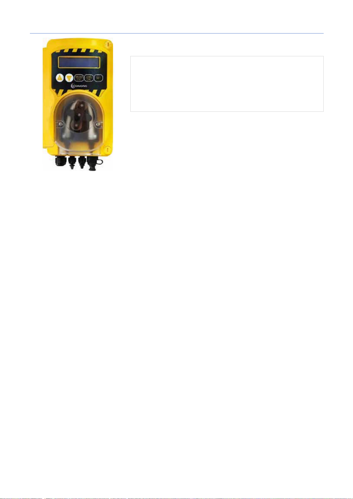
Smart Plus | pH ·
1
(1/2” GAS)
(5>?29-
1. +(!"*#$&(",)%( %$
'$&'$"
)1;10:;9/10183176E.C?;-.9=/8>=;3:-8163
>:;-/6183F><=;94<=/-Smart Plus>.103=1<D/=97A=9989
9=56EA1899=3<=9A835-:3=-83F
'1<9.6E0183138<=;>5@34<901;2-B3?<F/0-8897
;>59/90<=/17921=:;3/1<=35=;-/7-76E0143363
:9/;120183E:;3.9;-3<3<=17C
A: .<:A@29G
B: *
8>3=93;6G8H
@>A083 (I=50 )
<;;E7B69F@>
?@<G865
F:*/@D68 G: */@D68
K: )<2/
L: -).@>A08/:
C),,*::
*
A B C D E F G H I J K L M N
C: +>3=34;E7
8<:=938@16;@E
I=6 AA)
H:
(AB3>;E7
>/?@1<>
M: )*,*::
@>A08/:
D: :/;43@;E7
89/=/;(3/8” GAS)
I:
(AB3>;E7
>/?@1<>
N: -3>3C<2;/G:AB@/
29G89/=/;/1=>E?8/
HH
E: *3>4/@39F
/@D68/
2
J:
+/960><1<D;E7
>/?@1<>:)
Smart Plus pH 2 1 1 1 1 1 - 1 1 - 1 1 1 1
Smart Plus 2 1 1 1 1 - 1 - - 1 1 1 1 1
* )B5K:B=R=<G56@=JNDE:9FG57@RQG?C@=K:FG7CP@:A:BGC77BHGE=HD5?C7?=
0000138883
Page 3
Smart Plus | pH ·
2
*.215?2>EB?;1-/82:52/<=D>7-:532.-=
2 A
$!#$! !
4G=DEC9H?GN-.&0,3=GE:6HQGCFC6NIA:EDE:9CFGCEC;BCFG=DE==FDC@O<C75B==C6E5M:B===IE5B:B==
x $!"%:2>92C5/-6?2A595B2>752/.
x ,*+-'(&B:DC<7C@R>G:9:GRA=@=@Q9RAB:<B5?CANAF95BBNAEH?C7C9FG7CA=FDC@O<C75GO=@=
=<A:BRGO
pH (
!":
x +(,'(B:E:?CA:B9H:GFRK=FG5RF:EB5R?=F@CG5
x /:?CA:B9H:GFR9@RFB=;:B=RCGE=J5G:@OBN> (B5CFBC7:F:EBC>?=F@CGN
x /:?CA:B9H:GFR9@RDC7NL:B=RDC@C;=G:@OBN> (?5E6CB5G=@=6=?5E6CB5GB5GE=R)
( !":
x +(,'(B:E:?CA:B9H:GFR7F:7=9NCE85B=K:F?C8CI@CE5
-?B575%&<;1/2=32:D54:;>@<;F?;9@
1
2. !$()'*"+!!&%*()$%"
=@=@Q6N::8C9CDC@B=G:@OBN:?CADCB:BGN7?@QK5RI=A=K:F?=:DEC9H?GN
:-:5A:2=-><=;>?=-:G2?>G
:59-:52!
'-><;8;32:521-?B57-
(@RCDG=A5@OBC8C
FK=GN75B=RDC?5<5B=>
95GK=?5E5FDC@C;=G:
:8CD:ED:B9=?H@REBC
GEH6?:
*>?-:;/7-;.;=@1;/-:5G
18C@B5?@CB595GK=?5
B:9C@;:BDE:7NL5GO
!CGBCF=G:@OBC
7:EG=?5@=
:59-:52!
!><;8E4;/-:52>>;82/D9
A8;=-?;=;9:
2GC6NDE:9CG7E5G=GOE=F?
B:=FDE57BCFG==@=DC7E:;9:B=R
F=FG:ANFC6@Q95>G:
F@:9HQM=:=BFGEH?J==
1. .CA:FG=G:95GK=?9@R
=<A:E:B=RD:E:9RK:>?C>
I@CE5GCE5
2. 2GC6NHFGE5B=GO7=IE:7N:
GC?=DC9?@QK=G:7C9H7
65FF:>B:?GCK?:<5<:A@:B=R
3. /5FDC@C;=G:GCK?H7DENF?5
DEC9H?G5DCF@:RK:>?=
I@CE5GCE5
0000138883
Page 4
Smart Plus | pH ·
3
,%2%+10,+/*3*0,:
3.0 ÷ 10.0 pH
200 ÷ 999 mV
,%2%+10645%'-,
6.0 ÷ 8.0 pH
400 ÷ 850 mV
,%2%+104,(0%.%53*'1(,
5.0 ÷ 9.0 pH
300 ÷ 900 mV
1801459
± 0.04 pH
± 2 mV
!#
0.01 pH
1 mV
45180,-2,5%0,:
230 $;1<18199:/:>:6,%B
.%44,+1.:7,,
II
153*&.*0,*
10 $>
31,+'1),5*.9014590%414%
1,6 7C
%-42315,'1)%'.*0,*
1.5 -,<
%.,&31'-%)%58,-1'
#.>:8,>4C1=64
1451:0,*0%414%
(<:;:<B4:9,7E9:10:34<:.,941
':<;<19A88
*-471;C
185 x 124 x 110 88
*4
1.0 6/
1 2 3 4 5
6
4
3. # "$
2
(:067GC4>16,-17E;4>,94H6F716><:=1>4,;<10.,<4>17E9:;<:7:2199D56,-17E=1<.:?;<,.7194H6
.=;:8:/,>17E9:8?6:9>,6>?6:<:-64@47E><,
*A18,;:067GC194H:
1. ,>C46?<:.9H<131<.?,<=;<:0?6>:8
2. $A:09:5C,=>:>9D5=4/9,7
3. (:=710:.,>17E9D5;:<>0:;:794>17E9:
4. &,>C46>18;1<,>?<D9,.A:010,>C46.6:8;716>91.A:04>
5. $DA:09:1<171.=;:8:/,>17E9:/:9,=:=,=?A:56:9>,6><171$;1<18>:6,#
6. $DA:09:1<17104=>,9B4:99:
;1<10,.,18D50,>C46:848;?7E=:..:0:81<,
5=4/9,743,B44=?A:56:9>,6><171$;1<18>:6,#
(230 $;1<18>:6,).
&,>C46>18;1<,>?<D
2 ;
<:.:0, 3 ;<:.:0,
=4945
6:<4C91.D5
4. !"!
3
!%3%-5*3,45,-,
Smart Plus pH Smart Plus
)1B4<6?7HB4:99D59,=:=
$
)1;3<=-6D=3A=;>.5-$&'&88
$+%88
0000138883
Page 5
Smart Plus | pH ·
4
1) =TUVQGKReZILRO^LTOeNTG^LTOe
1
2 3 4
5
6
5. $%#&'"!&$% !$$%(SMART PLUS
4
2) =TUVQGKReZSLTc_LTOeNTG^LTOe
3) =TUVQG>LTd9b\UK
4) =TUVQG=
5) =TUVQGKReNGKGTOeZXYGIQO
6) DO[WUIUPKOXVRLP
)120.+,)/0.*0)--3 – ?GMSOYLOZKLWMOIGPYLIYL^LTOLXLQZTKQTUVQZ
AWOIIUKLQGMKUJUVZTQYGSLTdVGWGSLYWSUMLYHbYcTLVUXWLKXYILTTUONSLTLTXVUSU`cdQRGIO_
GROHWUIQG%"
XUXYWLRQGSO
UXZ`LXYIReLYXeTGMGYOLSQTUVQO
>LTdOSLLYQWZJUIZdXYWZQYZWZQGQYURcQUIbKUPKLYLKUVUXRLKTLJUVZTQYGVUKYILWMKLTOL
VGWGSLYWGZXYGTUIRLTTUJUTGMGYOLSQTUVQO
1 – >UMTUIbHWGYcUKOTONKUXYZVTb\eNbQUI$&!*(
2
3
4 = 30 XLQZTKKOGVGNUTUYKUXLQZTK
5
4
O AUKYILWMKLTOLYLQZ`LPTGXYWUPQOOVLWL\UKQXRLKZd`LSZVZTQYZ
UVWLKLReLYIUNIWGYQVLWIUSZVZTQYZSLTd
– 7.4pH (5-9pH) / 700mV (300-900mV)
– %3<69=-=OXRUYGELRU^c'345-F?ONQGe9bXUQGe
*
= 60 XLQZTKKOGVGNUTUYKUXLQZTK
4.1
4.2
4.3
4.4
FYUSLTdKUXYZVTUYURcQUKReSUKLRLPXWGNaLSUS&(#/.-10
CQUWUXYcVLWLKG^OORO
AUReWTUXYc^fYTGeTL^fYTGeOROTLY
8KWLXUYKU
RS485 Watchdog (9bQRXLQZTK
!65<0+;8(>0CWatchdog (%-8-/(+8;/2(, 90+5(30/(>0CWatchdog, 69:(56*2(,6/086*(50C
9)8699*C/0)
4.5
<SVZRcXROYW
;KOTO]GONSLWLTOeS4R
4.6
:ILYU^QO
@KTGYU^QG
9=6,5A-/5(?-50C
4.7
QR9bQR
9
$
:36.-5
9bQR
– (0-60SOT)
– (9QRd^LTU9bQRd^LTU)
– (8IYUBZ^TUP3)
Page 6
Smart Plus | pH ·
5
ι
7'47*,2"360&"
).'2'/*'
4'.1'2"4529
-2/,'15'!4(1''&./-"/++4,01/-$) – "(.*4'
"("4*',/01,*012'&'-<'4$960&*).'/;120%2"..*20$"/*<33062"/'/*'.1"2".'420$
'3-*1"2".'4215/,4".'/;$,04020.0//"60&*43</'#9-*).'/'/12*/"("4**,/01,*
01,-!)&#,,-"-&,3$,'7
"(.*4'*5&'2(*$"+4'$4'7'/*'3',5/&,/01,5 , 10.08:;,/010, * 534"/0$*4'
('-"'.0')/"7'/*'
$%'+-%'#,'70!)*63$,,-(.-#0!$1)-(
40#9$9,-;7*4:10&3$'4,553420+34$""(.*4'0&/0$2'.'//0,/01,***5&'2(*$"+4'*6$
4'7'/*'3',5/& 0)*20$,"*,"-*#20$,"04,-;7'/9 -<$960&"*)2'(*."0(*&"/*<0&/0$2'.'//0
/"(.*4',/01,*
*'!)
0-:,0,0%&"/"303/"60&*43<$2'(*.'0(*&"/*<0&/0$2'.'//0/"(.*4'*5&'2(*$"+4'*
/-003$13')/02-#
!40#93#203*4:)/"7'/*'
,/01,540-:,0$2'(*.'0(*&"/*<
&18EOffset/Slope#$
#(.40:-0;,-8.0*(1:-2567200?:6)A6:6)8(/0:B/5(?-50-2(30)86*20DOffset/SlopeE, &-<
*
=0340<//0%037'47*,">/"(.*4'*5&'2(*$"+4'$4'7'/*'3',5/&
120,254,*.'/;/"(*."+4',/01,*0
).'2'/*'
$"2*+/9'3*%/"-9
- LEV
- WDG
- OFA1 & OFA2
- $.0,(50-
- %6:62
(7-8-/(+8;.(-:9C
0000138883
Page 7
Smart Plus | pH ·
6
4 pH
7 pH
H2O
16
15
13
14
12
9
10
4 5 6 7 1 2 3
8
11
6.
5
5 9-2
#(9:8612(
2(30)86*20 pH
!"-*#20$,"pH
60 3',
!"-*#20$,"pH
60 ,!&
*.+)$-2$1%-$
0000138883
Page 8
Smart Plus | pH ·
7
475mV
H2O
9
10 4 5 6 7 1 2 3 8
11
6
7.
5 9-2
!(30)86*2($%
'$+*&(
60 ,!&
*.+)$-2$1%-$
0000138883
Page 9
Smart Plus | pH ·
8
8.
7
,-&
!"$( *#$+*)$3$,'*-
*0$%/$&',!&
,-&(
!"$( *#$+*)$3$#&$%
0)!()$ ,#J(&pH
*0$%/$&',!&
0000138883
( )
0)!()$ ,#J(&
Page 10
Smart Plus | pH ·
9
- "#!"#'&"#!*
!(8+
EN#"
1'-; OFA
OFF'!"
OFF'!"
."5'.)'423"$+)
7.4 pH
700 mV
",)#1/$+"
7 pH / 4 pH (2 :6?20
475 mV
! # " %
!0936:(
#0/201
8
9. "&#!
".*3'186,)4*.
$64),3< - #" !$#
-2,6,3.,-'
56,+,1'2.
+.'5'-43'
".*3'1
)6,2=
"046478<54840'
%930:.=
0'1.(64)0.
".78,23'=
4;.(0'
;.(0'Modbus
)6,2=
Smart Plus pH
(<5 pH)
(>9pH)
Smart Plus JDG ,/78).=
- # !!
(<100 mV)
!#('#%
- &)869B:-0/4-8-5$%
- 3C9)869(5#
- #"!"#(
#
- (4-50:-,(:?02030
);<-85A188076*:680:-
786>-,;8;2(30)86*20
- #%#'""#
!#! $%)
- #*"!"
-""##"*(
(:-
3/#8$/223"./$)390"1"-'3180/4-/,5".):$80/,.)3'2,'&4:7)'&'*23$);
x 9+,;6)3&4231/*23#/
x
!'-)3&)4%&1')#!*3&+./0+))#+,;6)3&4231/*23#/
x !6.&3-)$!3:
x !'-)3&
!'-)3&
x
"1"-'3180/4-/,5".): Smart Plus pH
63/"9#/223!./#)3:0!1!-&3190/4-/,6!.);
Smart Plus
0000138883
Page 11
Smart Plus | pH ·
3+1/*3&+197+4.!2/2!)
23!./#)3& 1/,)+ .!
23!./#)3& 1/,)+ .!
(2861:- 28A@2; 5(969( 0
10.
9
"-'."6,".%"
/326-,050:- 7,!.$ 0/3<.4#
, *2/&%).)3&,:##&15
0/#&1.4#&$/0/.!01!#,&.);
+14$/#/*231&,+)
/,./23:; /2#/"/%)3& , *
2/&%).)3&,: 4%&1')#!< &$/ #
.!3<.43/-0/,/'&.))
0/#&1.)3&1/,)+06.!01!#,&.);
+14$/#/* 231&,+) 3!+ 63/"9
7,!.$#92#/"/%),2<)/01!#/$/
2/&%).)3&,<
0/#&1.4#&$/0/.!01!#,&.);
+14$/#/*231&,+)
0000138883
23!#:3& , * 2/&%).)3&,: #
2//3#&323#4;8&&$.&(%/)01/0423)3&
7,!.$ 0/% .!01!#,<;8&* 1/,)+!
/#&1.)3& 1/,)+ # .!01!#,&.))
+14$/#/* 231&,+) /%./#1&-&../
01/#/%< 7,!.$ # $/,/#+4 .!2/2!
0/+! .& "4%&3 %/23)$.43 01!#9*
2/&%).)3&,:
736:56780.40:-?:6)A65(
*9:(3(5(4-9:6.
10
Page 12
Smart Plus | pH · ORP
(I=50 mm)
solution
solution
Calibration solution
PVC tube (4m)
PE tube (5m)
(1/2” M to 3/8” F)
Item*
System
1. PACKAGE CONTENT
WARNING!
Before carrying out ANY work inside control panel of the
Smart
Plus device, make sure you disconnect it from the power supply.
Failure to comply with the instructions contained in this manual
could cause injury to people and/or damage to the appliance and
the system.
A: Tapping saddle
for securing PSS3
onto 2” hose
B: Foot filter
(PP riser)
F: pH probe G: Redox probe
K: Water
L: 4x6
A B C D E F G H I J K L M N
(IDxOD mm)
C: Mounting
bracket kit
(I=6 mm screws)
H: pH 7 Buffer
M: 4x6 (IDxOD mm)
D: FPM Lip valve
(3/8” GAS)
I: pH 4 Buffer
N: Reducer for
injection valve
E: PSS3 probe-
holder
(1/2” GAS)
J: 475 mV
Smart Plus pH 2 1 1 1 1 1 - 1 1 - 1 1 1 1
Smart Plus ORP 2 1 1 1 1 - 1 - - 1 1 1 1 1
* The values from the table represents the number of items inside the package.
0000138883
rev. 1.0 EN
1
Page 13
Smart Plus | pH · ORP
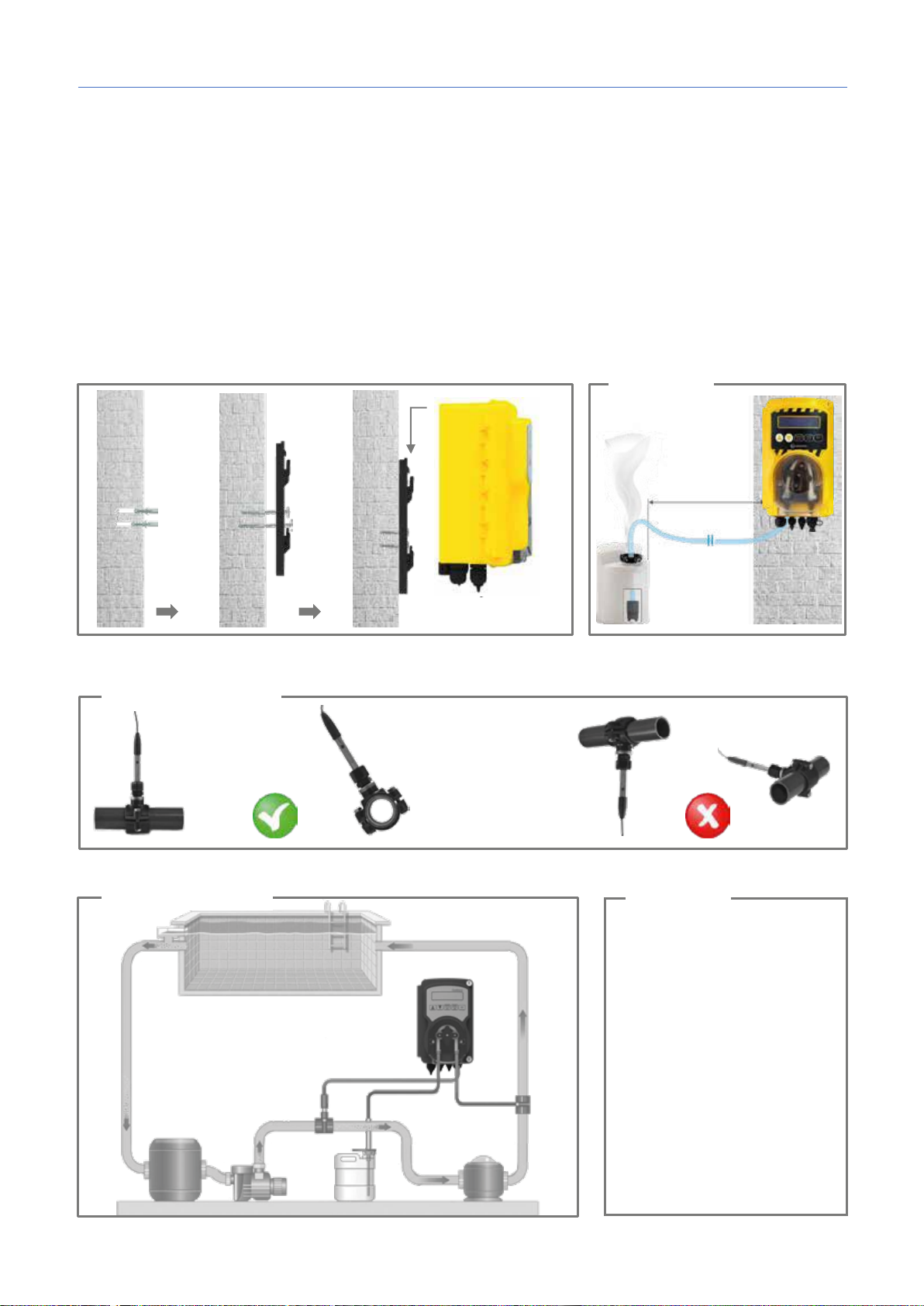
The probe’s angle of
vertical.
For optimum probe
Probe positioning
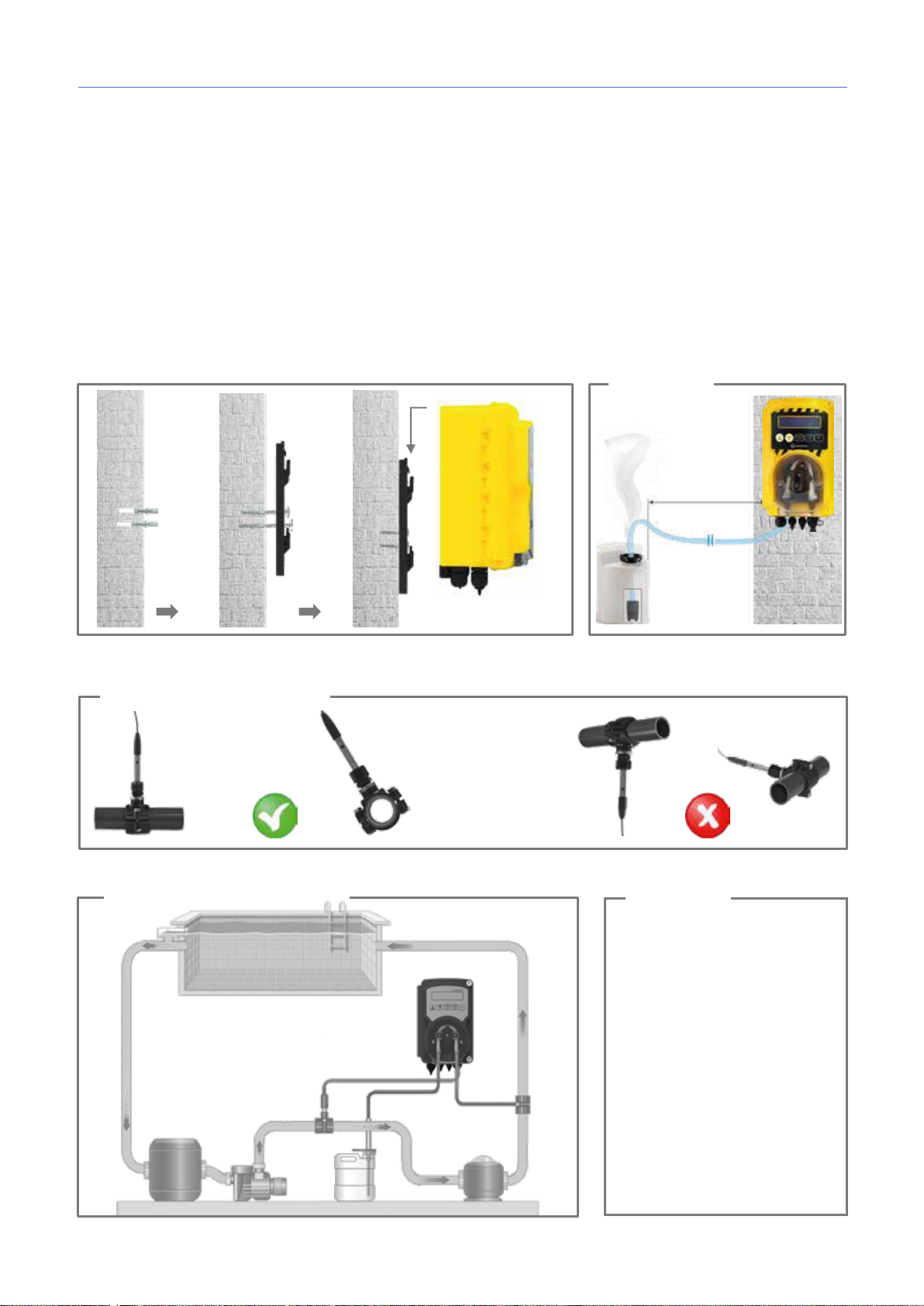
Make sure that the injection pressure is below 1.5 bar
2 m
WARNING!
These products are DANGEROUS and require special precautions during use, handling and storage.
x NEVER mix chemical products.
x NEVER allow children or people who have not read this manual to use or tamper with Smart Plusor
any of its peripheral components (including chemical products).
pH chemical products:
x ABSOLUTELY not recommended => pure sulphuric acid
x Recommended for lowering pH => negative pH (with a sulphuric acid base)
x Recommended for raising pH => positive pH (sodium carbonate or bicarbonate)
ORP chemical products:
x ABSOLUTELY not recommended => all types of organic chlorine
The pH / ORP probes are subject to wear and tear and therefore are not covered by the warranty.
1
2. INSTALLATION INSTRUCTIONS
Warning!
reading, position it
perpendicular to the
tubing.
Installation plant
inclination must never
exceed 45° from
Warning!
Use with salt chlorinator:
For the pH systems, to prevent the
risk of system malfunctioning or
damage, observe the following
instructions:
1. Position the pH measuring
probe prior to the chlorinator
cell.
2. To eliminate eddy currents,
connect the pool water to an
electrical ground point
3. Position the product injection
point after the chlorinator cell.
0000138883
rev. 1.0 EN
2
Page 14
Smart Plus | pH · ORP
Measure range
3.0 ÷ 10.0 pH
200 ÷ 999 mV
Set Point range
6.0 ÷ 8.0 pH
400 ÷ 850 mV
Alarm range
5.0 ÷ 9.0 pH
300 ÷ 900 mV
Accuracy
± 0.04 pH
± 2 mV
Resolution
0.01 pH
1 mV
Power supply
230 VAC 50 Hz
Insulation class
II
Consumption
10 W
Pump flow rate
1.6 l/h
Max. back-pressure
1.5 bar
Probe calibration
Automatic
Pump state
Proportional dosing
Peristaltic tube (ID x OD mm)
Norprene 4.8 x 8 mm
Dimensions
185 x 124 x 110 mm
Weight
1.0 kg
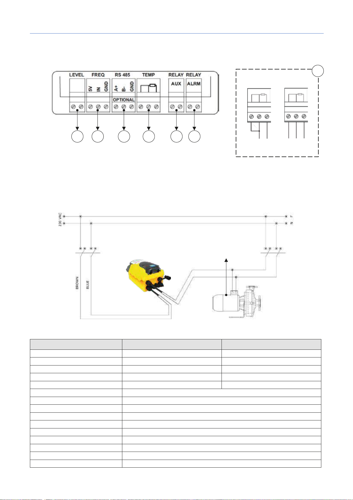
1 2 3 4 5
6
PT100 temperature probe
2 wires 3 wires
4
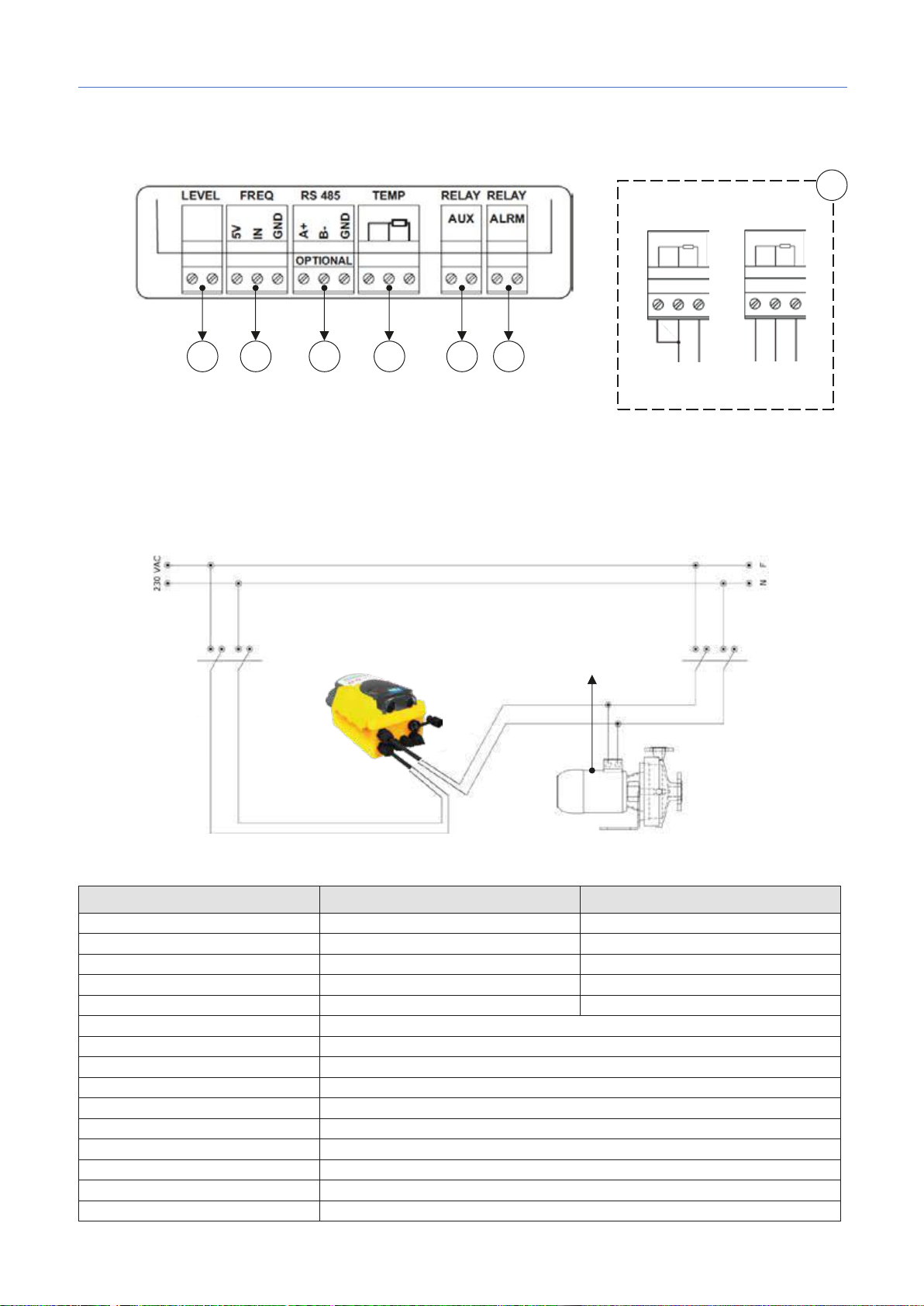
3. ELECTRICAL CONNECTIONS
2
Connect the power supply cable to the mains and the servocontrol pre-wired cable to the auxiliary contact of the
filter box (230 Vca).
Wiring diagram:
1. Input Level Probe (Product Tank)
2. Input Frequency signal by Water meter pulse sender
3. RS485 Serial Port (optional)
4. Input Temperature Probe (PT100 sensor not included)
5. Output Relay Auxiliary Pump (Dry contact, Relay 250 Vac 10 A)
6. Output Relay Alarm remote (Dry contact, Relay 250 Vac 10 A)
3
4. TECHNICAL SPECIFICATIONS
Specifications
Recirculating pump
230V
Smart PluspH Smart Plus ORP
(H x W x D mm)
0000138883
rev. 1.0 EN
3
Page 15
Smart Plus | pH · ORP
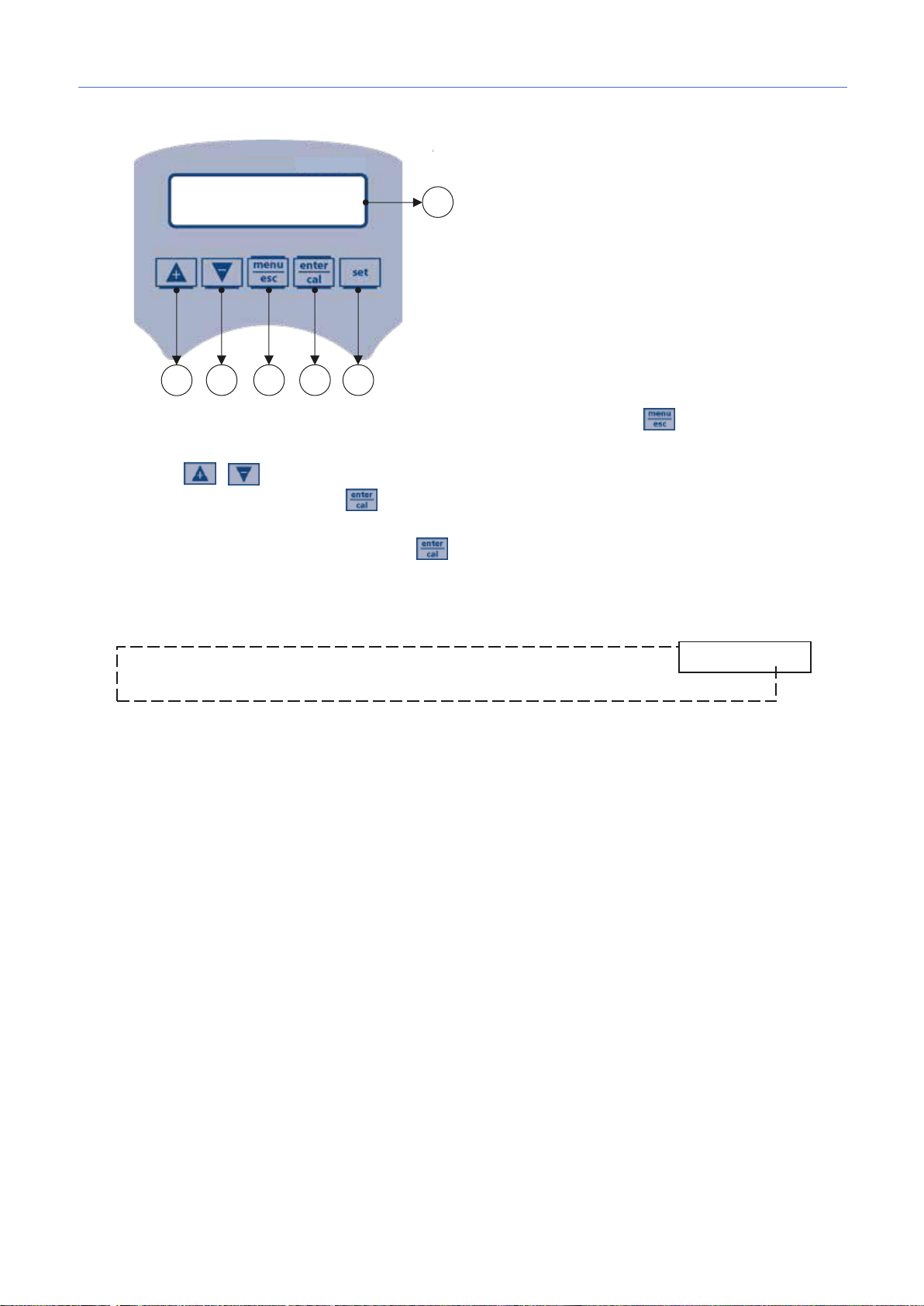
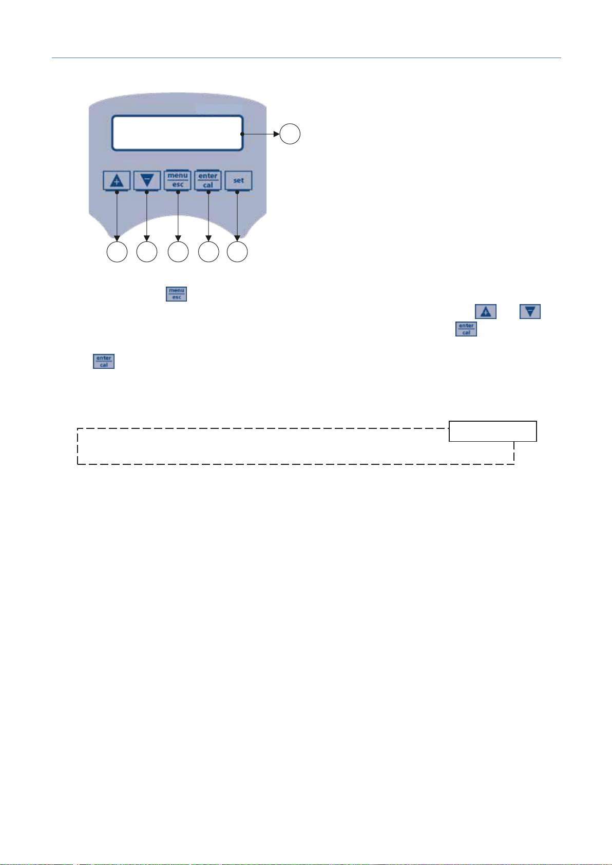
1) Button to increase the value
1
2 3 4
5
6
* Timed dosing only
4
5. SETUP INSTRUCTIONS POOLMATCH SYSTEM
2) Button to decrease the
value
3) Button Menu/Esc
4) Button Cal/OK
5) Button to set the setpoint
6) Digital display
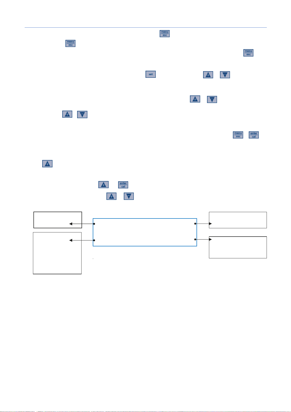
Program Setup – Press for 5 seconds
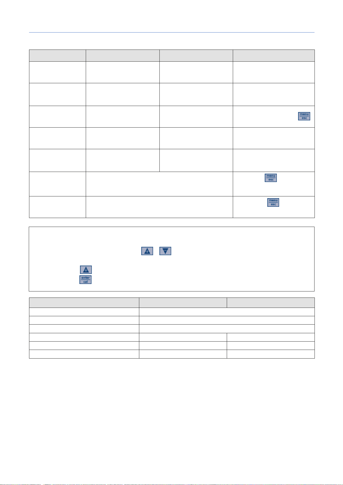
At the entry of each menu item, the parameter can be directly modified using the arrow keys ( and ).
Confirmation of the current setting and switching to the next item is done by pressing the button.
The menu has a circular structure: once you arrive at last item, the confirmation of the parameter set by
pressing , determines the return to the first menu item.
1 – It is possible to select between 5 available languages: EN, FR, IT, DE, ES
2
3
4
5 = 60seconds (range from 1 to 360 seconds)
4
4.1 – (Enabled/disabled)
4.2
4.3
4.4
This menu is available only for models that have the RS485 Modbus connector
Baud Rate (2400, 4800, 9600 or 19200)
Polarity (Even, Odd or None)
Address (from 1 to 240)
RS485 Watchdog (Off, 1-30000 seconds)
Watchdog Config (Hardware Reset, Watchdog Alarm, Stop Dosing, Reset Comunication)
4.5
Pulse/ liter 1:1
Unit measure m
4.6
Two points
Single point
Referece
4.7
On/Off
Timed
Off
– 7.4pH (5-9pH) / 700mV (300-900mV)
– Acid (Acid/Alka) / Low (Low/High)
= 30seconds (range from 1 to 360 seconds)
– (Auto/Manual 25°C)
– (0-60min.)
³, l.
0000138883
4
Page 16
Smart Plus | pH · ORP
ι
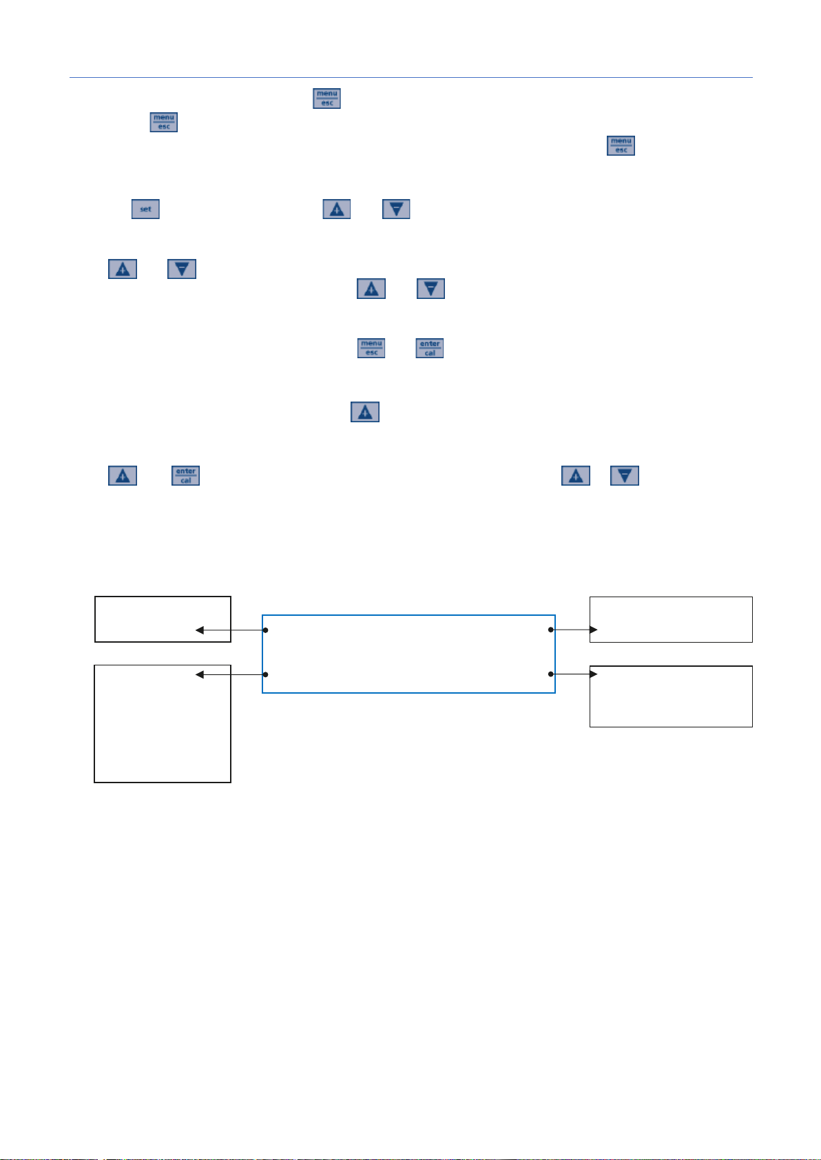
Alarm list
- Flow
Flowater totalizer
Resetable
Temperature
measure
pH/ORP
measure
Save and exit Program setup – Press
Pressing the key determines the exit from the programming menu with saving of the parameters, if the
parameter of the menu item in which one is in has not been changed when pressing the key.
Set Point adjustment
Press the button for 3 seconds, use and to set the desired value.
Stand-by mode (backlight on)
Press and buttons simultaneously for 5 seconds to switch off the unit backlight. Dosage and
calibration are disabled. To exit standby, press and buttons simultaneously.
Priming
Only while the pump is in stand-by press down and in the same time.
Flowrate counter reset
To reset value of "Permanent Totalizer" press button for 3 seconds, in stand-by mode only.
Offset/Slope Menu
Press and buttons the unit show Offset/Slope calibration value, press or to scroll the
menu.
- LEV
- WDG
- OFA1 & OFA2
- Stand By
Absolut
0000138883
5
Page 17
Smart Plus | pH · ORP
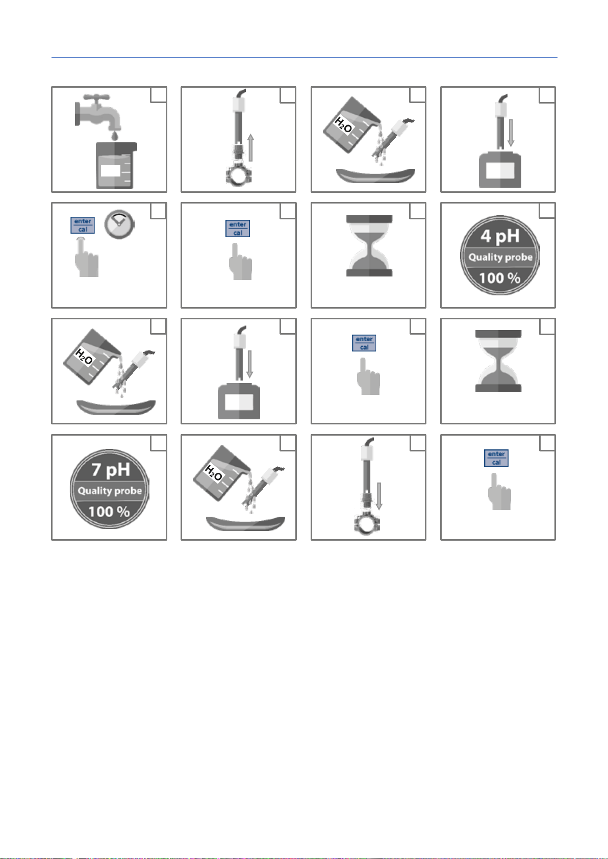
5 s
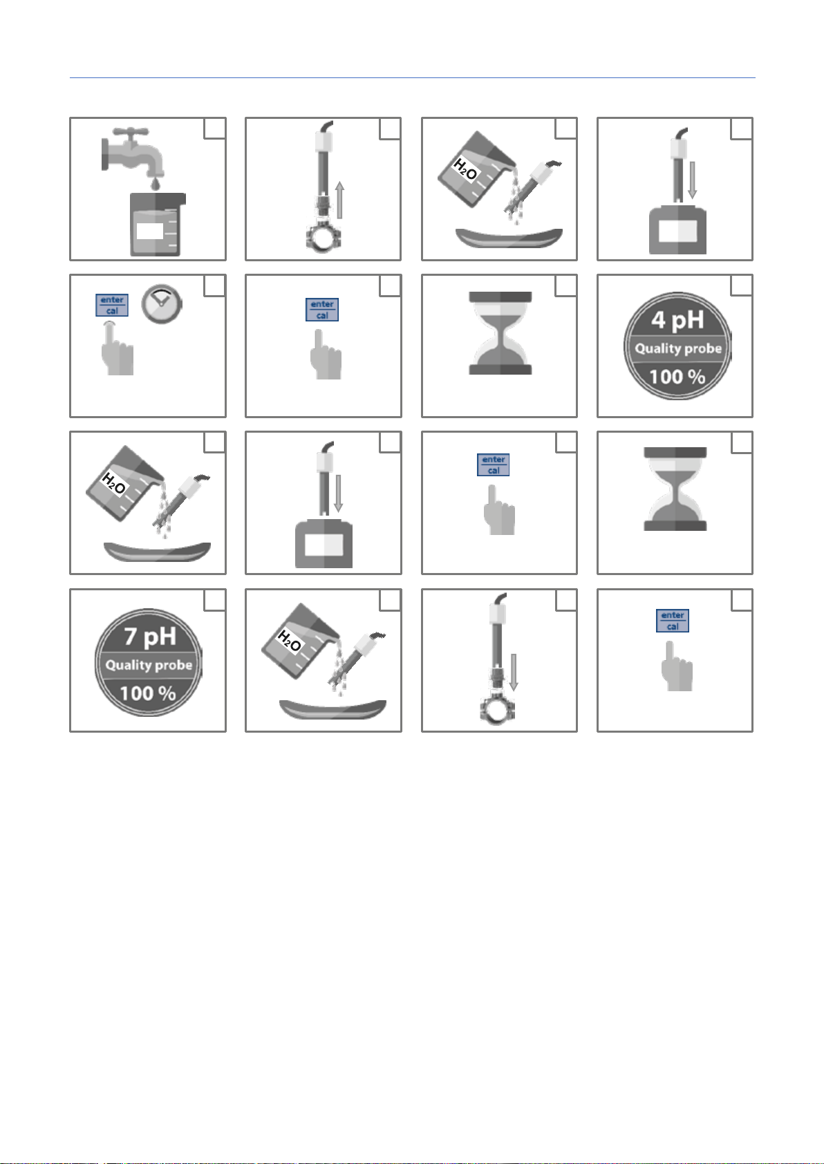
Set pH calibration
4 pH
60 s
7 pH
60 s
4 pH calibration
7 pH calibration
H2O
Save and exit
16
15
13
14
12
9
10
4 5 6 7 1 2 3
8
11
5
6. pH CALIBRATION
0000138883
6
Page 18
Smart Plus | pH · ORP
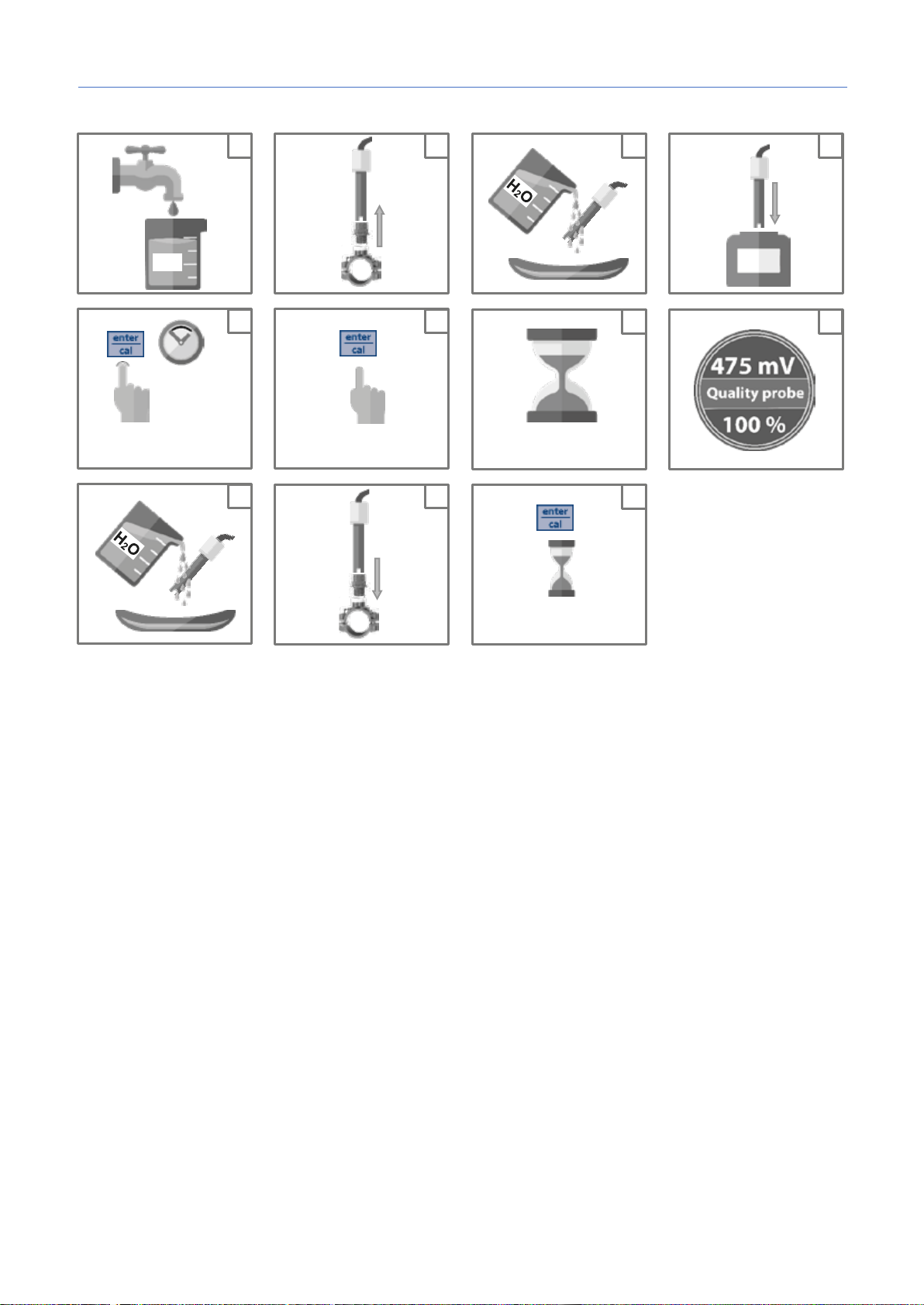
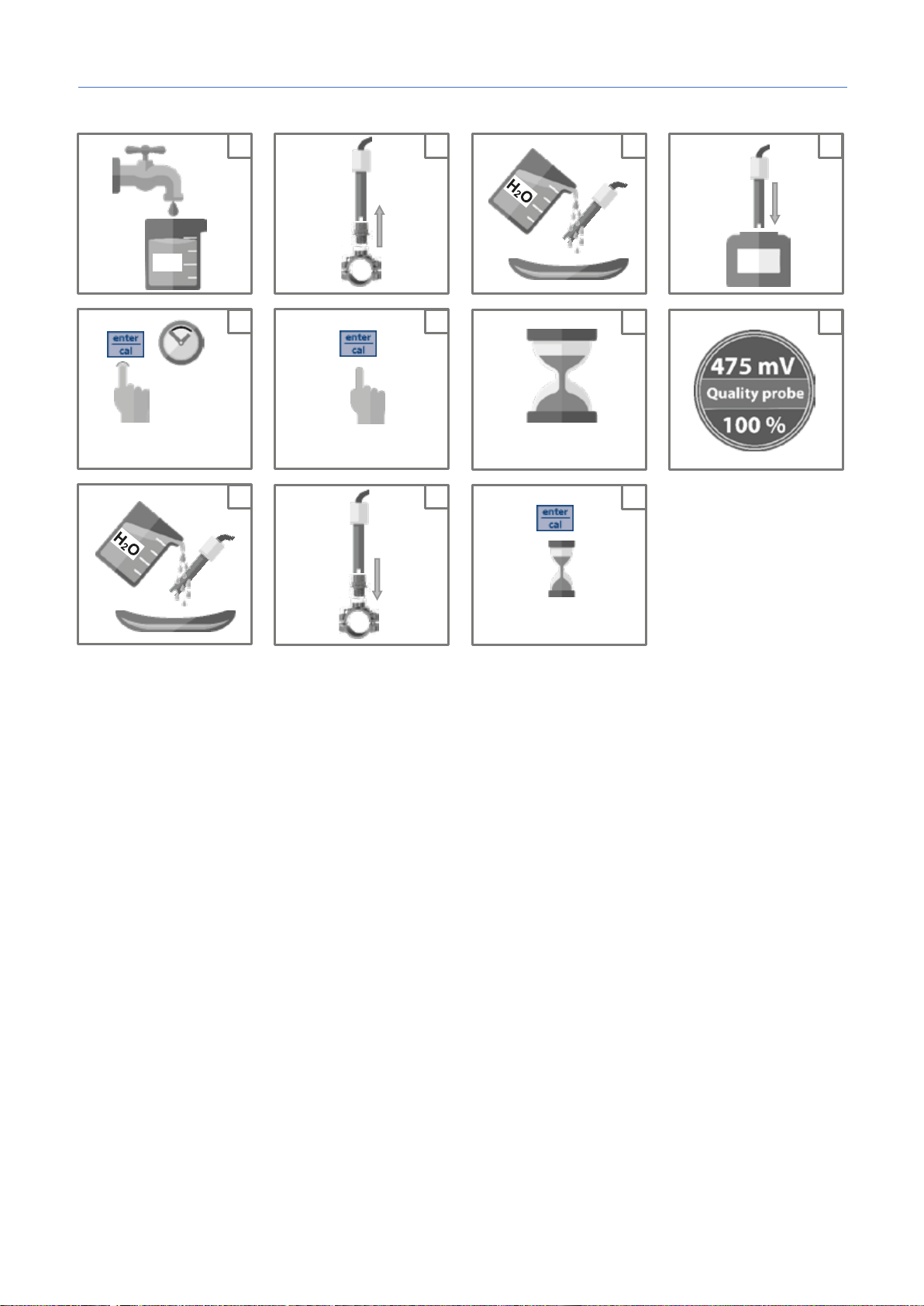
5 s
Set ORP calibration
475mV
60 s
H2O
475 mV calibration
Save and exit
9
10 4 5 6 7 1 2 3 8
11
7. ORP CALIBRATION
6
0000138883
7
Page 19
Smart Plus | pH · ORP
7
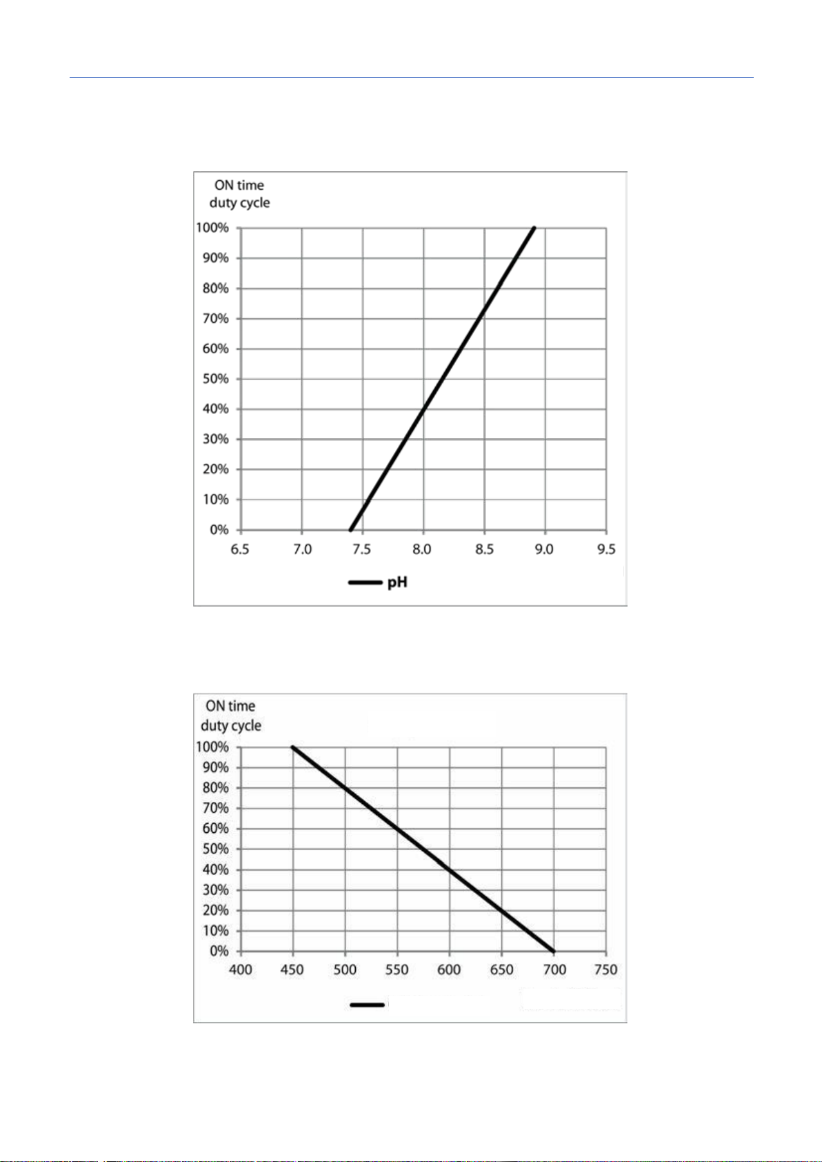
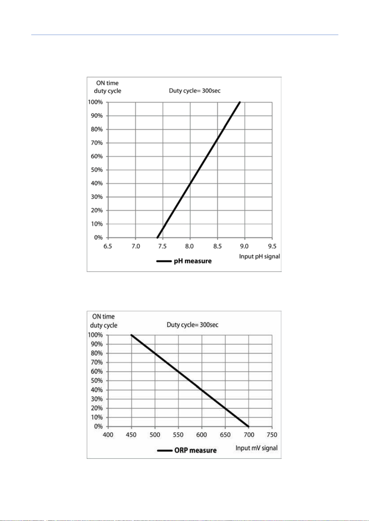
8. PROPORTIONAL DOSING
Setpoint = 7.4 pH
Dosing mode = Acid
Setpoint = 700 mV
Dosing mode = Low
0000138883
8
Page 20
Smart Plus | pH · ORP
- Restore Probe or Buffer
calibration procedure
to restore Default
- Broken Unit
Language
EN
Time OFA
OFF
Flow Input
OFF
Set Point value
7.4 pH
700 mV
Calibration
7 pH / 4 pH (2-point)
475 mV
Dosing Method
Acid
Low
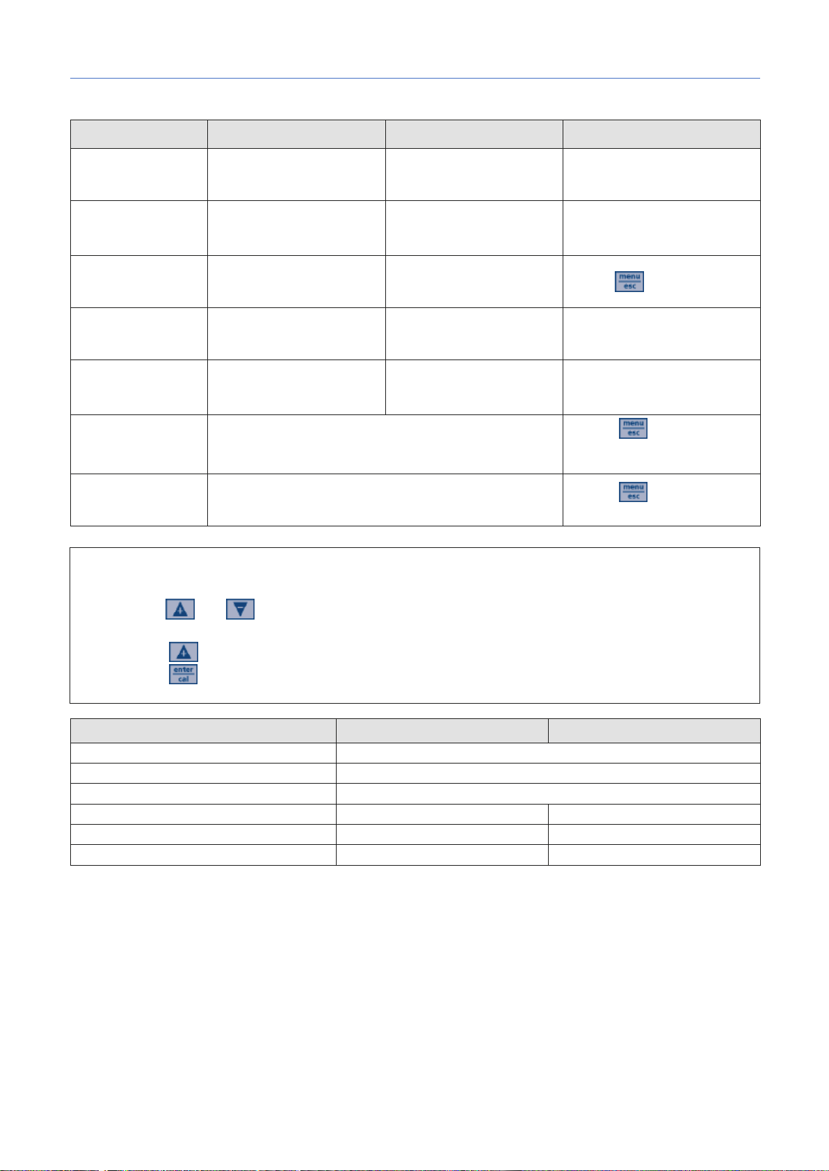
9. ALARMS
8
Alarm Display Smart Plus pH Display Smart Plus ORP Actions to do
Level - Restore Product tank
Measure out of
range
OFA Alarm
(time >OFA time)
Flow Rate - Restore Flow Rate
Calibration
Function
System Error
Modbus Error
To restore the default parameters, follow the steps below:
x Power off the Smart Plus unit
x Keep and pressed and power on the unit
x The unit will flash
x Press
x Press to restore the default parameters.
(<5 pH)
(>9pH)
(<100 mV)
- Replace or check the
measure probe
- Restore pH / ORP
measure
- Push to reset
solution and repeat
- Press
parameter
- Press to reset
- Restore communication
Default Parameters Smart Plus pH Smart Plus ORP
0000138883
9
Page 21
Smart Plus | pH · ORP
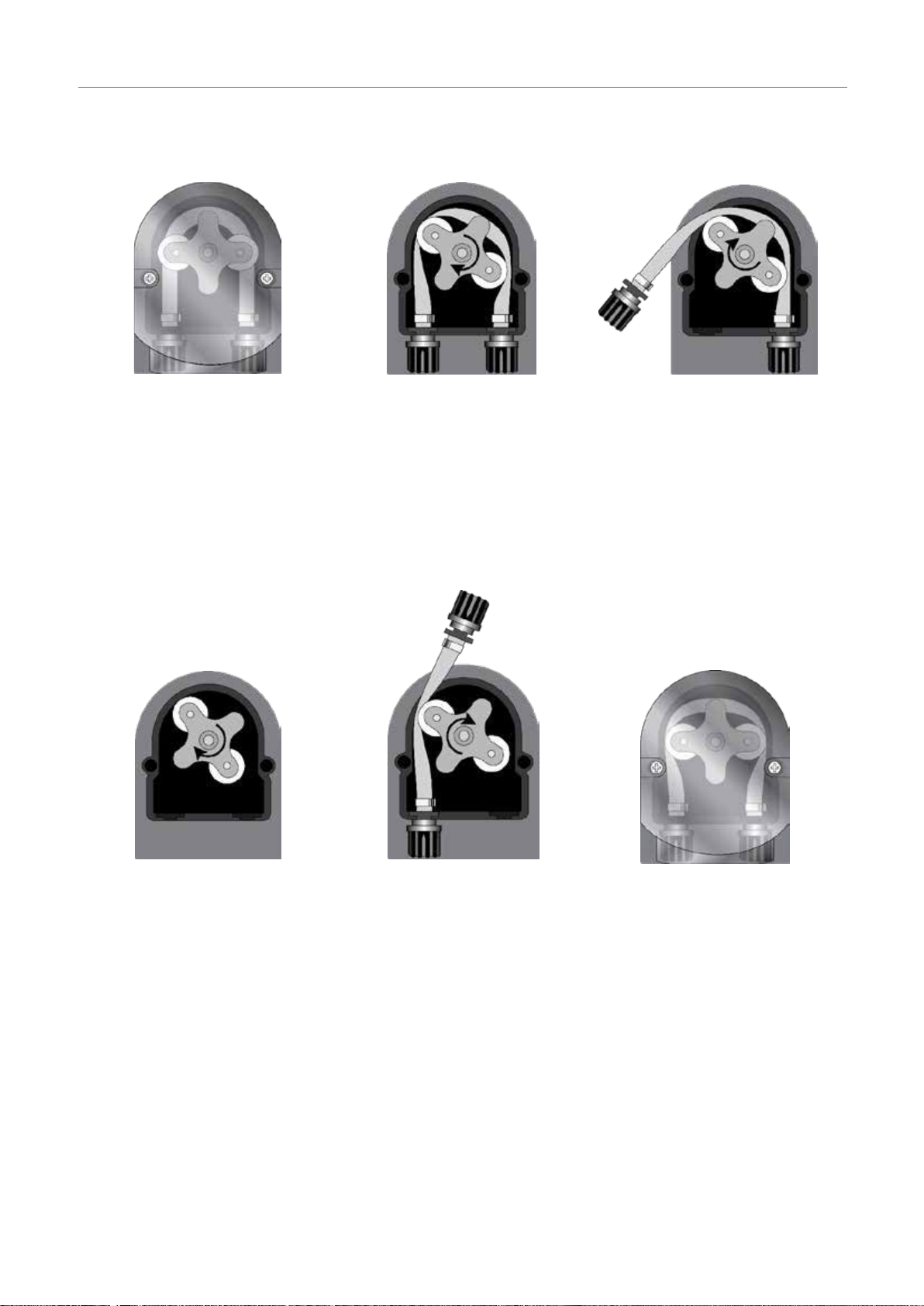
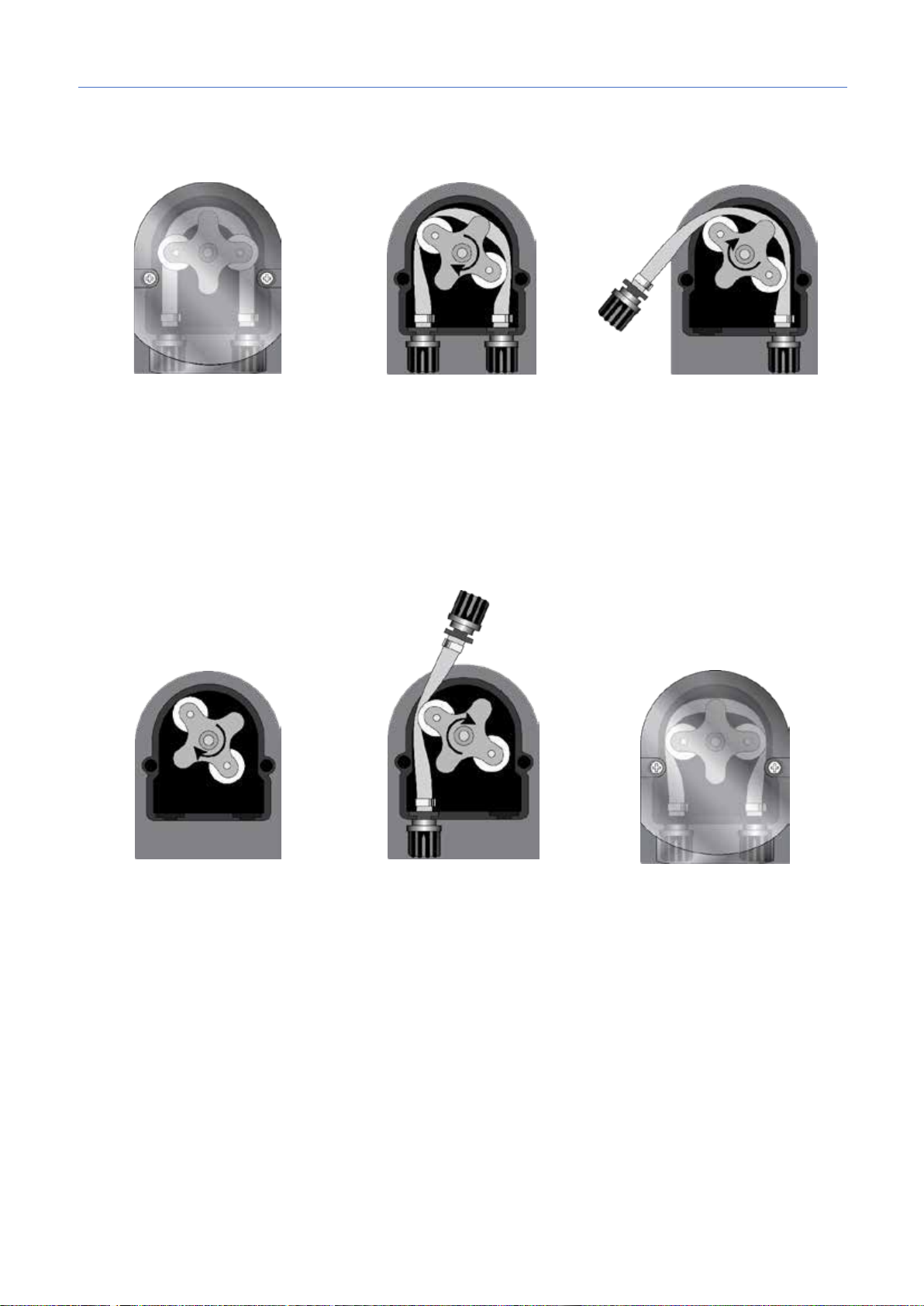
Open the pump’s lid and release the
Position the roller at 7h05, turning it
Completely release the left
connector.
Position the roller at 7h05, turning
Insert the left connector into the
the right connector is reached.
Close the pump’s lid and press its
10. HANDLING
9
Hose replacement:
hose by pulling the left connector
upward.
in the direction of the circular arrow.
connector, holding it taut towards
the outside, and turn the roller in the
direction of the circular arrow so that
the hose is freed up to the right
it in the direction of the circular
arrow.
0000138883
relative housing and pass the hose
under the roller’s guide. Turn the
roller in the direction of the circular
arrow, simultaneously accompanying
the hose into the pump’s head, until
surface hard so that it is properly
locked into place.
0
 Loading...