

Page 1

INSTRUCTION MANUAL ON
MODEL DIGI-7
CABLE LOCATOR
US PATENT NO. 4,233,561
1212 N.E. 5th Street • Redmond, OR 97756
TEL (541) 548-2110 FAX (541) 548-2117
www.aquatronics.com
aquatron@aquatronics.com
Page 2

I. ACCESSORIES Page #
a. Inductive Couplers . . . . . . . . . . . . . . . . . . . . . . . . . . . . . . . . . . . . . . . . . . . . . . . . . . . . . . . . . . . . . . . . . . . . . . . . .2
2
II. BATTERY TEST
a. Receiver . . . . . . . . . . . . . . . . . . . . . . . . . . . . . . . . . . . . . . . . . . . . . . . . . . . . . . . . . . . . . . . . . . . . . . . . . . . . . . . . . 2
b. Transmitter . . . . . . . . . . . . . . . . . . . . . . . . . . . . . . . . . . . . . . . . . . . . . . . . . . . . . . . . . . . . . . . . . . . . . . . . . . . . . . .2
III. OVERVIEW
1. Receiver . . . . . . . . . . . . . . . . . . . . . . . . . . . . . . . . . . . . . . . . . . . . . . . . . . . . . . . . . . . . . . . . . . . . . . . . . . . . . . . . .2
a. Automatic Mode . . . . . . . . . . . . . . . . . . . . . . . . . . . . . . . . . . . . . . . . . . . . . . . . . . . . . . . . . . . . . . . . . . . . . . . . 3
b. Peak Mode Automatic . . . . . . . . . . . . . . . . . . . . . . . . . . . . . . . . . . . . . . . . . . . . . . . . . . . . . . . . . . . . . . . . . . .3
c. Null Mode Automatic . . . . . . . . . . . . . . . . . . . . . . . . . . . . . . . . . . . . . . . . . . . . . . . . . . . . . . . . . . . . . . . . . . . . 3
d. Low Signal Automatic . . . . . . . . . . . . . . . . . . . . . . . . . . . . . . . . . . . . . . . . . . . . . . . . . . . . . . . . . . . . . . . . . . .3
2. Transmitter
a. Direct Output . . . . . . . . . . . . . . . . . . . . . . . . . . . . . . . . . . . . . . . . . . . . . . . . . . . . . . . . . . . . . . . . . . . . . . . . . . 4
b. Matching Output Impedance in Manual Mode . . . . . . . . . . . . . . . . . . . . . . . . . . . . . . . . . . . . . . . . . . . . . . . . 4
IV. OPERATING INSTRUCTIONS
1. Direct Tracing . . . . . . . . . . . . . . . . . . . . . . . . . . . . . . . . . . . . . . . . . . . . . . . . . . . . . . . . . . . . . . . . . . . . . . . . . . . .5
2. Locating in Automatic Peak Mode . . . . . . . . . . . . . . . . . . . . . . . . . . . . . . . . . . . . . . . . . . . . . . . . . . . . . . . . . . . . 6
3. Locating in Manual Peak Mode . . . . . . . . . . . . . . . . . . . . . . . . . . . . . . . . . . . . . . . . . . . . . . . . . . . . . . . . . . . . . . 6
4. Locating in Automatic Null Mode . . . . . . . . . . . . . . . . . . . . . . . . . . . . . . . . . . . . . . . . . . . . . . . . . . . . . . . . . . . . . 7
5. Locating in Manual Null Mode . . . . . . . . . . . . . . . . . . . . . . . . . . . . . . . . . . . . . . . . . . . . . . . . . . . . . . . . . . . . . . . 7
6. Tracing with the Inductive Coupler . . . . . . . . . . . . . . . . . . . . . . . . . . . . . . . . . . . . . . . . . . . . . . . . . . . . . . . . . . . 8
7. Inductive Tracing . . . . . . . . . . . . . . . . . . . . . . . . . . . . . . . . . . . . . . . . . . . . . . . . . . . . . . . . . . . . . . . . . . . . . . . . . . 8
8. Correcting for a Broad Peak Reading . . . . . . . . . . . . . . . . . . . . . . . . . . . . . . . . . . . . . . . . . . . . . . . . . . . . . . . . .8
9. Determining Depth. . . . . . . . . . . . . . . . . . . . . . . . . . . . . . . . . . . . . . . . . . . . . . . . . . . . . . . . . . . . . . . . . . . . . . . . . 9
10. Inductive Coupler used as a Receiving Antenna . . . . . . . . . . . . . . . . . . . . . . . . . . . . . . . . . . . . . . . . . . . . . . . .10
1
Page 3
DIGI-7
The Digi-7 line locator is two locators built into one. Both receiver and transmitter will operate in a full automatic mode or
a full manual mode with the push of a button.
ACCESSORIES FOR THE MODEL DIGI-7 LINE LOCATOR
The Model I.C.49, I,C,56, or I.C.56WT Inductive Couplers are used to help identify one line from other utilities even though
they are sharing a common ground.
BATTERY TEST
RECEIVER: When the receiver is first turned on, all of the information available on the LCD is displayed for approximately
3 seconds. A battery symbol in the upper right hand corner will show the approximate battery voltage is then displayed for
about 2 seconds. With the receiver turned on, pushing the battery test button will show the approximate battery voltage and
the battery symbol. If the batteries reach a low voltage during operation, this battery symbol will start flashing. When a
low battery condition exists, the batteries should be replaced with six AA batteries. Any type of AA battery can be used,
but Alkaline will provide a much longer life. A thumbscrew allows entry to the battery compartment where a battery holder can be removed for battery replacement. Disconnect the battery snap connector to remove the battery holder.
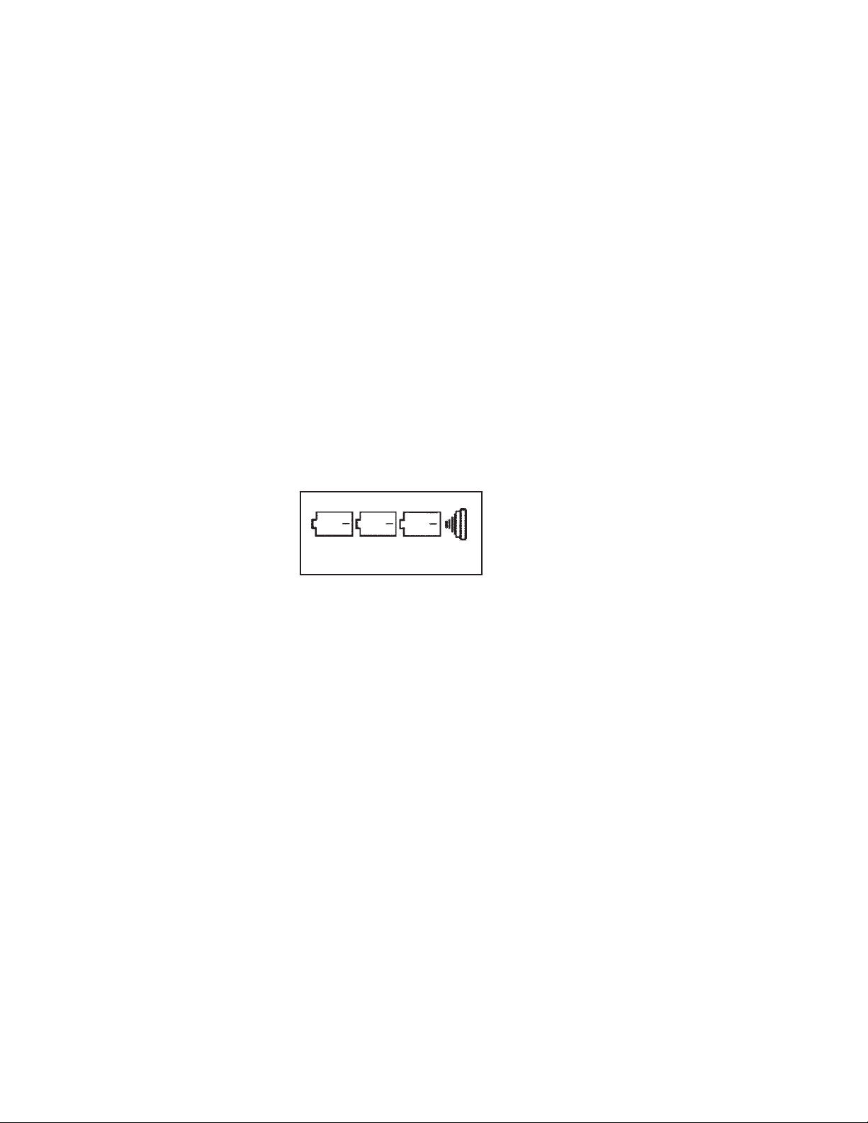
TRANSMITTER: The battery voltage is continuously monitored when the transmitter is on. If the voltage should drop, the
decimal point on the numerical display will start to flash. The batteries should be replaced by 6 alkaline D cells. Remove
the battery tube plugs to change the batteries. Three batteries are located on each side. The + side of the batteries face
"IN" when being installed. See Fig. 1. After one minute of operation, the transmitter will enter a battery saving mode and
shut off all test circuits that are not needed. At this time, the numerical display will start flashing every 10 seconds.
Figure 1
3X D CELL PER SIDE
OVERVIEW
RECEIVER
Turn on the receiver by rotating the large knob (on-off / sensitivity / volume) control clockwise. When the receiver is first
turned on, the LCD (meter display) will display all of the information available in the different modes of operation. The
receiver will go through a self-test of all functions and display the battery condition. This will take somewhere between 5
to 7 seconds before the receiver is ready to operate. The receiver will always power up in the Automatic Peak Mode of
operation.
Flags or little arrowheads on the display point to the mode of operation, either Peak or Null. On the right side of the display,
the decal has a "LOW SIGNAL" and a "PEAK" flag. On the left side of the display the decal has a "MANUAL" and a "NULL"
flag. These arrowheads indicate which antenna is operating and which mode the receiver is operating in. The settings can
be changed with push buttons that are located between the handle and the LCD display.
The button closest to the handle changes the receiver operation between NULL and PEAK. The button nearest the display
changes the receivers operation from AUTOMATIC to MANUAL as well as battery test.
2
Page 4

Automatic Mode
In the automatic mode, the receiver operates with a minimal amount of input or interpretation from the operator. The operator simply follows the Left/Right guidance system. The operator can choose to display the locate information in either the
Peak or Null modes depending on preference. The On-Off/Volume/Sensitivity Control is used only to adjust the loudspeaker volume in the automatic mode.
While locating, the display provides three different pieces of information to the operator. First, the instrument tells you
which way you need to go, left or right. The pitch of the tone played by the loudspeaker will also change from left to right.
A down arrow will be displayed when the receiver is directly over the line under test. Second, the instrument has a three
digit numerical readout (0-999) on the LCD. This provides absolute signal strength in the automatic mode and is used to
compare signal strength from one utility to another. This comparison should occur when the down arrow is displayed.
Third is the bar-graph display. The bar-graph on the LCD simulates the result you would see from an analog panel meter.
IN THE AUTOMATIC MODE, LEFT/RIGHT GUIDANCE ARROWS WILL POINT TO THE DIRECTION OF THE TARGET
LOCATE. AT THE EXACT LOCATE, A DOWN ARROW WILL APPEAR. WHEN THE DOWN ARROW IS PRESENT, THE
LEFT/RIGHT GUIDANCE ARROWS AND THE SOUND FROM THE SPEAKER WILL NOT BE PRESENT.
Peak Mode - Automatic
The bar-graph display will build up as you approach the line, and "peak" as you cross it, and then roll off on the other side.
The guidance arrows will change direction as you cross the line, the tone pitch will change and you should also see the highest absolute signal strength number. These four things should all correlate with each other. In the peak mode, the receiver must be at right angles to the direction of the conductor's path.
Null Mode - Automatic
The bar-graph display will be high as you approach the line, and sharply drop off as you cross it, and sharply increase on
the other side. The guidance arrows will change direction as you cross the line, the tone pitch will change and you will see
the highest absolute signal strength number.
Absolute signal strength will not change between peak and null modes. It is strictly the amount of raw signal the instru-
ment is seeing on the line.
WHEN LEFT/RIGHT GUIDANCE ARROWS ARE PRESENT ON THE DISPLAY, THE RECEIVER MUST BE AT RIGHT
ANGLES TO THE CONDUCTOR PATH FOR BEST SIGNAL READINGS ON A LOCATE.
WHEN MAKING A LOCATE IN THE AUTOMATIC MODE, IF THE DOWN ARROW CANNOT BE FOUND, OR THE DOWN
ARROW DOES NOT AGREE WITH THE BAR-GRAPH READING, THE RECEIVER IS TELLING THE OPERATOR IT IS PICKING UP A DISTORTED RADIO WAVE AND THE LOCATE COULD HAVE AN ERROR IN ITS POSITION.
Low Signal-Automatic
The Digi-7 receiver continuously monitors the absolute signal strength present on the conductor under test. If the signal
level drops below 260 on the display, the low signal flag will begin to flash. This is a warning to the operator that signal is
getting low and something must be done with the transmitter to improve signal strength if a longer trace is needed. At 230
and below, the direction arrows will also flash along with the low signal flag. At this point, the locate may be unreliable. If
the locate is not finished, something must be done with the transmitter to increase signal on the line being traced.
NOTE: If the receiver is switched to the manual mode, the tracing range will be extended.
3
Page 5

TRANSMITTER
The Digi-7 transmitter has both INDUCTIVE and CONDUCTIVE methods to apply signal to the conductor to be traced.
On the faceplate, two rocker switches are located in the upper right hand side. One switch turns the transmitter on
and off. The second switch is used to operate in the Automatic or Manual mode. This switch also allows the operator
to change the direct output tap in the manual mode. The power control knob is used to control the output level for
extremely long or deep locates. Most locates can be made with the lowest power setting.
When the transmitter is turned on, the TAP # window will show a self-test mode. If nothing is plugged into the output
jack, the letter "A" will then appear on the numerical display. This indicates the transmitter is set up for Inductive
Antenna Operation. See INDUCTIVE TRACING on page 8 for set up and use.
With the direct output cable assembly or Inductive Coupler plugged into the direct output phone jack, the transmitter
switches from the Inductive Antenna mode to the Conductive mode of operation. In the Automatic mode, the transmitter will match the output impedance and select the right tap that is needed for the best trace. In the Manual mode, the
tap switch must be pushed until the tap # desired by the operator appears in the numerical display. Manual mode can
also be used for mismatching the transmitter to the line being traced to correct for a broad peak reading. See page 8
DIRECT OUTPUT
With the direct output cable assembly plugged into the transmitter, connect the red lead clip to the conductor being
traced. Insert the ground rod in the earth and clip the black lead clip to it. It is important to obtain the best ground
possible. This may be within inches of where the transmitter is connected, or several feet away.
HINT: Pouring water on the ground rod can improve the ground connection in dry soil. A FIVE-GALLON CONTAINER
OF WATER IS A VERY IMPORTANT ACCESSORY TO HAVE WITH YOU.
Turn on the transmitter and have the power control at low power. If the transmitter is in the automatic mode, the
numerical display will set itself to the correct tap number for the best locate. If the soil conditions or power level change
while locating, the transmitter will track that change. If for some reason manual selection of the output is required, the
following guidelines should be noted.
MATCHING THE TRANSMITTER IMPEDANCE IN THE MANUAL MODE
In wet soil, tap # 1. In average soil or medium dry, use tap # 2. In very dry soil conditions, or with the ground plate
on asphalt or concrete, use tap # 3. Tap # 4 & 5 are used for mismatching the impedance. If unsure as to what tap number is needed, make your output connection and turn the transmitter on. Set the tap switch to tap 1, 2, or 3. Move out
several feet away from the transmitter, turn on the receiver and lay it down where the LCD (liquid crystal display) can
be seen while standing at the transmitter. Go back to the transmitter and find the tap number that provides the highest numerical number on the receiver display. This will provide the most signal on the line for the best trace.
4
Page 6

OPERATING INSTRUCTIONS
Direct Tracing
With the direct output cable assembly plugged into the phone jack on the transmitter, connect the red clip to the line being
traced and the black clip to the driven ground that is supplied with the instrument. When connecting the red clip lead to the
line being located, make sure the clip is attached to clean bare metal. For maximum tracing range, the ground rod should
be extended at full length and at right angles to the direction of the conductor being traced. (HELPFUL HINT - Most locates
are a short distance and the ground rod can be placed near the transmitter. It is more important to have a good ground than
extending the ground rod farther out.)
Figure 2
Figure 3
Figure 4
A GOOD GROUND NEAR THE TRANSMITTER WILL PRODUCE BETTER LOCATES THAN A POOR GROUND FARTHER
AWAY FROM THE TRANSMITTER. NEVER PLACE THE GROUND ACROSS OTHER UTILITIES IN THE AREA. THIS WILL
INDUCE A TONE ON THEM EVEN WHEN THEY ARE NOT USING A COMMON GROUND.
OVER ASPHALT OR CONCRETE, CLIP THE BLACK CLIP TO A SMALL ALUMINUM PLATE AND LAY IT DOWN. POUR
WATER ON THE GROUND PLATE. THIS CAN PROVIDE A GOOD LOCATE IN MOST CASES.
Turn the transmitter on with the power control at low power. The transmitter will go through a self-test on the numerical
display window. This will take several seconds. When the self-test is complete, the automatic impedance matching will set
the transmitter to the correct output tap and this number will then be displayed. The line is now ready to be traced.
5
Page 7

DEFINITION OF A PEAK: See Figure 5. A low signal reading is found on both sides of the conductor, and a high
signal is found directly over the conductor.
Figure 5
LOCATING BY THE PEAK METHOD - IN THE AUTOMATIC MODE
When the receiver is turned on, it will power up in the automatic peak mode. The volume control knob can be adjusted for
the amount of sound the operator wants to hear.
With the transmitter connected and operating, move out 5 to 10 feet from the transmitter and walk a half circle. Record all
of the peak signals found in the half circle and notice the absolute signal display number at each peak signal found.
Depending on the depth, the strongest signal may not be the utility being traced, but the strongest signal is a good starting
point.
When a location has been made, the bar-graph and absolute signal reading will both provide the highest value. A down
arrow will appear directly over the locate and the directional arrows and tone will not be present. Moving the receiver from
side to side will produce the directional arrows and tone change each time the receiver passes over the conductor.
LOCATING BY THE PEAK METHOD - IN THE MANUAL MODE
Locating a peak in the manual mode is the same as in the automatic mode, except the loudness control becomes the sensitivity control and the left/right guidance arrows are not present. How much of the sensitivity control is being used will be
displayed in the upper left hand corner of the display as a percentage number between 0 and 100. (The number 25 will be
1/4 or 25% from a zero setting. At 50, the sensitivity control is half way to full or 50%) In the manual mode, the tone will no
longer change pitch as the receiver passes from one side of the conductor to the other side. This means, the Digi - 7 will be
acting like an analog locator using a digital display.
CAUTION: NEVER SWING A RECEIVER FROM SIDE TO SIDE. IN THE PEAK, NULL, AUTOMATIC OR MANUAL MODE,
THE RECEIVER SHOULD ALWAYS BE MOVED FROM SIDE TO SIDE WITH THE ANTENNAS PARALLEL TO THE
GROUND.
6
Page 8

DEFINITION OF A NULL - See Fig. 6. A high signal reading is found on both sides of the conductor, and a loss of signal
is found directly over the conductor.
Figure 6
LOCATING BY THE NULL METHOD - IN THE AUTOMATIC MODE
The receiver will always power up in the AUTOMATIC PEAK MODE OF OPERATION. Turn on the receiver and rotate the
large knob until the desired level of sound is being heard. In the Auto Mode, the knob is a "VOLUME" control. Push the
NULL button for NULL operation. A little flag at the lower left corner of the display will point to NULL.
Move out 5 to 10 feet from the transmitter and walk a half circle around transmitter until the bar-graph display starts to
increase. At some point, the bar-graph will drop to a small value and then increase. Directional arrows are also present
that will indicate what direction is needed to find the conductor. As the receiver moves past the null point, the directional
arrow will change and a different tone will be heard. Each time the conductor is crossed, the directional arrow will change
and the sound being heard will also change. The numerical signal strength meter will read absolute signal and it will be at
a maximum number, even though the receiver is in the null mode of operation. In the Automatic Null Mode, the receiver will
provide direction to the conductor with left/right arrows on the display so the receiver must be at right angles to the conductor path in the Auto Mode.
LOCATING BY THE NULL METHOD - IN THE MANUAL MODE
Locating in the manual mode allows the operator to take control of the receiver sensitivity. The large knob that was the
loudness control in the auto mode is now the sensitivity control.
Change the receiver to Manual and push the Null switch for Null operation. A flag will point to the word NULL on the lower
left corner of the LCD display. In the upper left corner of the display, a numerical read out will appear. This 0 to 100 reading will indicate the position of the sensitivity control as it did in the manual peak mode.
The method of locating a Null in the manual mode is identical to the automatic mode except the operator is required to adjust
control on the receiver. The left-right guidance arrows will not be present on the display, so the antennas do not have to be
at right angles to the conductor path. The tone pitch will remain constant on both sides of the conductor.
As shown in Fig. 6, a large signal will be present on both sides of the locate and a minimum signal will be found directly over
the locate. The sensitivity control setting controls the display response. Using a higher sensitivity setting can sharpen
broad null readings. They may be made wider by reducing the sensitivity.
7
Page 9

Figure 7
INDUCTIVE TRACING
Set the transmitter directly over and in-line with the conductor to be traced. The "CONDUCTOR PATH" decal should be over
and in-line with the target conductor. Turn on the transmitter and set the power control to low power. More power can be
used, but low power will help reduce signal being applied to other utilities that may be in the same area.
On low power, the operator should be 20 feet in the manual mode and 30 to 35 feet in the automatic mode from the transmitter before a locate is started. The transmitter is radiating signal in all directions and operating too close to the transmitter could produce a transmitter locate rather than the target conductor locate. The receiver can now be used to locate
the conductor path in either the null or peak method.
If the locate requires an inductive trace at less than 20', set the receiver to MANUAL PEAK. Make the locate and mark it.
Now set the transmitter at a 45° angle on the target line instead of in-line with it. Go back and check the locate. If the locate
is no longer present, it was probably the transmitter that was being located instead of the target conductor.
TRACING WITH THE INDUCTIVE COUPLER
To use the Inductive Coupler, the line being traced must be grounded at both ends. This ground can be through a load of
some type like a transformer winding to the ground rod. The circulating signal from the Inductive Coupler must travel from
one end of the conductor to the other end through the earth and it cannot do so unless both ends are grounded.
The Inductive Coupler plugs into the direct output phone jack on the transmitter. The transmitter will automatically set up
tap # 1. This is the correct tap and should be selected if the transmitter is operating in the manual mode. When a phone
plug is installed in the direct output phone jack, the Inductive Antenna is now disabled out of the circuit so the receiver can
be used very close to the transmitter.
When using an Inductive Coupler, it should always be used around the outer sheath of a telephone or CATV cable before the
sheath bond breaks out. It can also be placed around the service drop at the house without removing the house protector
cover. A coupler can also be placed around a plastic or metal duct as long as there is a conductor inside the duct.
For best results, the mating parts of the Inductive Coupler core material should be free of dirt or contamination at all times.
Some limited range may be obtained if the coupler is not closed, but maximum tracing range will require the coupler to be
completely closed with both sides of the core material touching each other.
CORRECTING FOR A BROAD PEAK READING
When using an Inductive Coupler or the Direct Output mode of tracing, there may be times when a wide or broad peak reading is found near the transmitter. If this occurs, the receiver is being flooded with too much signal. Reducing the signal on
the line being traced can be accomplished by setting the transmitter to Manual Mode and the tap switch to number 4 or 5.
This will be the wrong impedance tap for a long or deep trace, but the reduced signal will un-flood the receiver and a sharp
crisp peak reading can be found near the transmitter.
8
Page 10

Figure 8
DETERMINING DEPTH
The Digi-7 can be used in several ways to locate the depth, however the Manual Mode - NULL is the easiest to use. The null
or peak method can be used, but in the peak mode the position of the receiving antenna is more critical and this is not the
case in the null mode.
On a 45º right triangle, two of the sides will always be equal. There is a bubble level to the left of the receiver’s NULLPEAK switch. When the bubble is half way between the center ring and the outer black housing, the instrument is at a
45º angle.
When the line has been located and marked, move off to one side of the location with the bubble set at 45º. Move away
until a null point has been found with the nose of the antenna touching the ground. Mark that spot. See Fig 10. Measure
the distance between the LOCATION MARK, and the DEPTH MARK. The depth of the line will be the distance between
these two marks.
The sensitivity control may have to be adjusted while making a depth reading. The null found should be sharp enough to
pinpoint the spot you want to mark. Also, bear in mind that the distance is calculated at a 45º angle from the receiving
antenna. The calculation will have to take into account any slope of terrain, or the height that the receiving antenna is
held above the ground when the depth measurement is being made.
When possible, a depth reading should be made from both sides of the line being traced. If both measurements agree
with each other, the operator can assume a good depth measurement has been made, and the locate is fairly accurate. If
the two depth readings do not agree with each other, relocate the line and then repeat the two depth measurements. This
will verify if there is an error with this locate. If the two depth readings are still not the same, care should be used when
digging this locate. Other utilities are in the same area, creating a distorted field pattern. This distortion means your
locate could be marked off to one side of the line actually being traced.
9
Page 11

INDUCTIVE COUPLER AS A RECEIVING ANTENNA
The receiver must be in the "Manual Peak Mode" when an Inductive Coupler is being used as a receiving antenna.
On the receiver, two phone jacks are present. One is for headphone use. The other one is for plugging in the I.C. 49 Inductive
Coupler. The regular receiving antennas are automatically switched out and the I.C. 49 becomes the receiving antenna.
This can be helpful in identifying one cable from a bundle. EXAMPLE - URD feed from a house to the transformer. Place
an Inductive Coupler around the meter riser at the house. This can be a transmitter fed coupler or the I.C. 56 WT Wireless
Inductive Coupler. All of the signal will be on all three cables to the transformer. At the terminal block junction in the transformer, the signal will divide down, so a lesser amount of signal will be on all of the other cables leaving the terminal block.
With the I.C. 49 being used as a receiving antenna, clamping around each cable connected to that one terminal block will
identify which cable is feeding the house where the transmitting coupler is located. All cables should be tested with the same
sensitivity setting for comparison purposes.
SERVICE AND WARRANTY
Instrument Service
If for any reason you have trouble, or require assistance with your instrument, contact the nearest Aqua-Tronics sales outlet. You may also write, call, or e-mail directly to Aqua-Tronics Inc. manufacturing plant and provide full details of your problems or needs.
Warranty
All Aqua-Tronics products are warranted against defective materials and workmanship.
The Model Digi-7 line locator comes with a one-year warranty period from date of purchase.
Aqua-Tronics Inc. will repair or replace all products which prove to be defective during the warranty period. All warranty
repair will take place at our manufacturing plant or one of our field service centers. The decision of determining warranty
defects from abuse or breakage, and where the instrument is to be repaired, lies with Aqua-Tronics Inc.
If product is sent to Aqua-Tronics Inc. for service, please send it pre-paid. If the service is covered under warranty, the product will be returned pre-paid. No other warranty is provided or implied.
10
 Loading...