

Aquatic Industries 260330M Installation Manual
Aquatic products may be specified as Lasco Bathware.
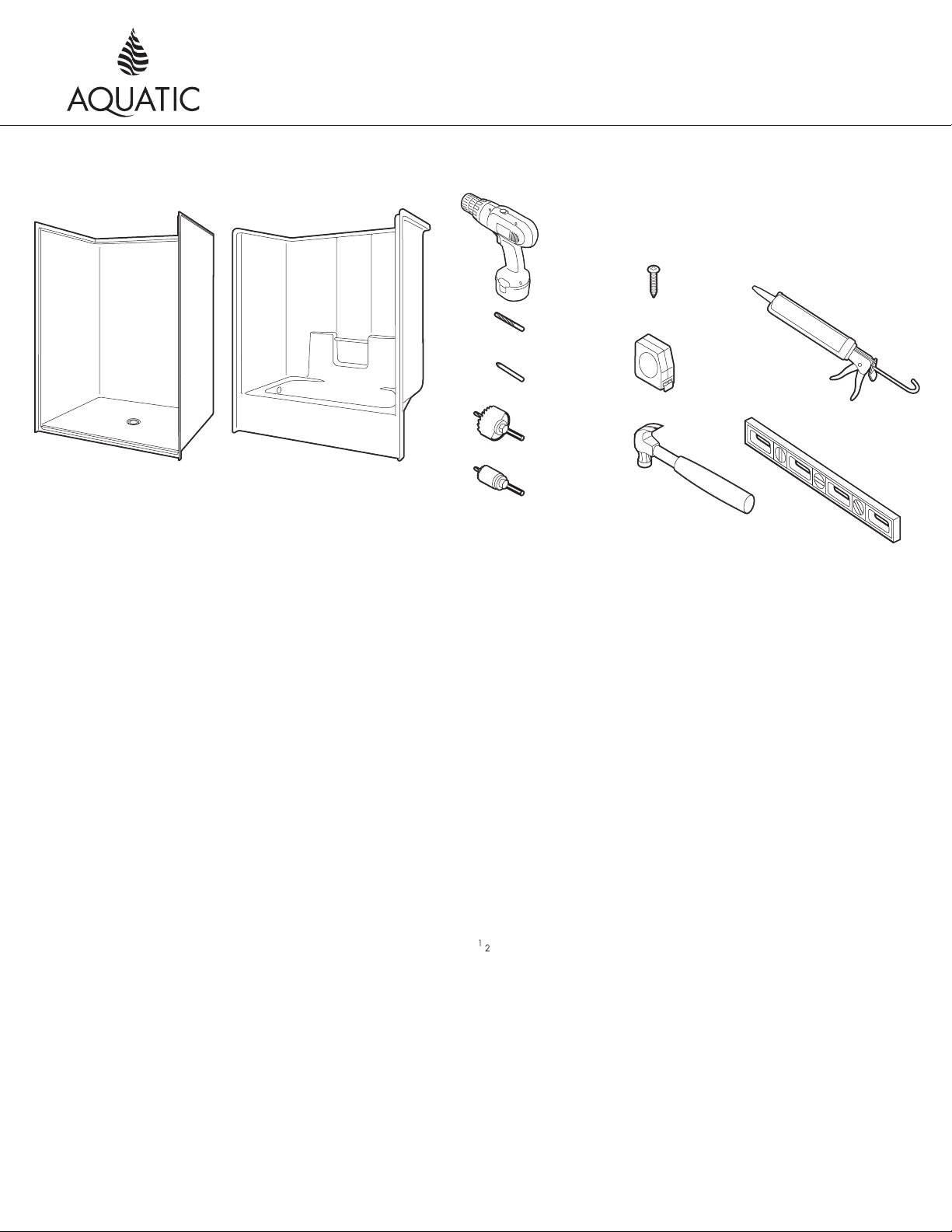
Resistant Silicone Sealant
Items Included Tools Needed
Installation Instructions
Shower Stalls/Tub-Showers
Fax on Demand # 1900
Shower or Tub-Shower
Product illustration may not be representative of your unit.
Drill
3/16” Drill Bit
Screw Driver Bit
3-1/2” Drill Bit
1” Drill Bit
#8 X 1”
Pan Head
Screws
Tape Measure
100% Mildew
LevelHammer
NOTICE: Please inspect the unit thoroughly before installation to make sure it has not been damaged during transportation.
Under no circumstances should a damaged unit be installed. Neither Aquatic nor the distributor will be responsible for removal
or reinstallation costs should a replacement be necessary due to installation of a damaged unit.
PRE-INSTALLATION PLANNING
1. Unit must be placed within bathroom area before completion of door framing or, if preferred, studs may be omitted or
knocked-out to permit unit placement.
2. Review job print and Aquatic rough-in dimensions; verify all key dimensions against actual job conditions . Make sure framed-in
alcove is of proper size, square and plumb; check floor for levelness. The wood blocks attached underneath the bottom of the
bath fixture units are for storing and shipping. These blocks need not touch the sub-floor.
3. The blocks and/or legs attached underneath the bottom of the bath fixture are an integral part of the support system and should not
be removed. Although these blocks and/or legs need not touch for an acceptable install, this may be an indication that the unit
and/or sub-floor are out of level. To achieve a superior install, Aquatic recommends to shim, or support with foundation material,
any gap under the support blocks and/or legs.
NOTE: It is a best practice in the industry to set the unit in foundation material. Industrial plaster, mortar mix or non-shrink grout are
recommended for a firmer bottom support.
4. If fire-rated alcove is required, approved finish material must be in place prior to unit installation to meet fire safety requirements
of local building code and/or FHA/HUD Minimum Property Standards.
NOTE: Finished alcove must have interior dimensions
shown on rough-in diagram to permit installation of unit.
5. Showers: Provide 6” (150mm) floor opening for 2” (50mm) IPS and drain connection.
Tub-Showers: Provide 6 x 12 (130 x 300) floor opening for 1 1⁄2
” (40mm) drain, waste and overflow (DWO) kit.
NOTE: Be sure floor opening location matches bath fixture drain location.
6. To avoid obstruction, make sure that supply lines and valve plumbing are not strapped to studs and do not project into
alcove. Also, drain pipe must not project above floor level prior to installation.
7. Make sure all plumbing is complete and to code.
8. To prevent scuffing while installing unit, cover the entire bottom of the unit with a piece of cardboard or other protective material.
9. Fasten drain fitting to unit before installing [see manufacturer’s instructions].
NOTE: Fasteners for wood framing—11⁄2” galvanized roofing nails or #10 x 11⁄2” self-tapping washer head screws; for concrete
or block walls—1” concrete nails and nailing tool; for steel studs (18 ga.)—drill flanges and studs with 5⁄32” carbide bit and use
#12 x 1” sheet metal screws.
Aquatic • 8101 E. Kaiser Blvd. • Anaheim, CA 92808 • (800) 877-2005 • FAX (714) 998-5340 • www.aquaticbath.com
— 1 —

Aquatic products may be specified as Lasco Bathware.
6“x12”
6“ Dia.
A
B
C
INSTALLATION PROCEDURE
1A 1B
Installation Instructions
Shower Stalls/Tub-Showers
Fax on Demand # 1900
A
B
Note: If fire-rated alcove is required, approved finish material must be in place prior to unit installation to meet fire safety requirements of local
building codes and/or FHA/HUD Minimum Property Standards.
Check dimensions. Make sure framed-in alcove is of proper size, square and plumb.
For showers, refer to Diagram 1A; for tub-showers, refer to Diagram 1B.
2A
B
A
C
2B
B
A
B
C
A
A
B
C
If mounting fittings — from stable reference points (back wall studs, floor) measure the locations of spout and valves. Note measurements below.
For showers, refer to Diagram 2A; for tub-showers, refer to Diagram 2B.
3
Note measurements here:
Tub Filler: ________________________________
Valve: ___________________________________
Shower Arm: _____________________________
Valve: ___________________________________
(Mark dimensions only if shower arm is plumbed
within bath fixture wall area.)
Aquatic • 8101 E. Kaiser Blvd. • Anaheim, CA 92808 • (800) 877-2005 • FAX (714) 998-5340 • www.aquaticbath.com
Mark fitting locations. (Refer to measurements from step 2.) Using a
hole saw (fine tooth or abrasive grit cutting edge), make necessary
openings for filler and valves, drilling from inside (smooth side) out.
— 2 —
 Loading...