

Page 1

Installation Instructions
4-Piece A2 Composite Shower System Models
GENERAL INSTALLATION INFORMATION
Thank you for selecting Aquatic. To insure maximum performance from the Aquatic fixture, please read and follow the
instructions and cautions. Carefully inspect the new Aquatic fixture for any shipping damage. If such damage is found,
report it to your vendor immediately. Under no circumstances should a damaged Aquatic fixture be installed. Aquatic and it’s
Distributor are not responsible for removal or reinstallation costs if a replacement fixture is necessary due to installation of a
damaged fixture. Do not make modifications to the Aquatic fixture. This could adversely affect the safety and performance of
the Aquatic fixture and void the warranty. Any failure to comply with the installation instructions and cautions may void the
warranty. For questions concerning installation and maintenance of the Aquatic fixture, contact Technical Services at
1-800-945-2726.
Items Included
Tub/Shower Shower
Tools Needed
Drill
3/16"
Drill Bit
Phillips Screw Bit
Hole saw
#10 x 1 ½ self –tapping
washer head screw
OR 1 ½ Galvanized roofing nail
Customer Service (800) 945-2726 • www.aquaticbath.com
Hammer Level
Tape
Measure
— 1 —
Safety Glasses
NOTE: Caulk is NOT
needed for this installation.
Page 2

Installation Instructions
4-Piece A2 Composite Shower System Models
PLEASE READ ALL INSTALLATION INSTRUCTIONS COMPLETELY BEFORE BEGINNING THE INSTALLATION.
PRE-INSTALLATION PLANNING
1. Review job print and Aquatic rough-in dimensions; verify all key dimensions against actual job conditions. MUST INSURE ROUGH
DIMENSIONS ARE PROPER AND SQUARE.
2. Locate studs as required and in remodeling, if necessary, add studs at each end to provide a vertical nailing surface for the side
nailing flanges of the Aquatic fixture.
3. Make sure framed-in framing pocket is of proper size, square and plumb; check floor for level. Some shimming between the stud
frame and fixture may be required.
4. DO NOT install the product over open floor joist. Product should not require any additional support if the subfloor is square and
level with framing. Shimming or foundation material may be required for additional support, if subfloor is uneven.
5. If fire-rated framing pocket is required, approved finish material must be in place prior to unit installation to meet fire safety
requirements of local building code and/or FHA/HUD Minimum Property Standards.
NOTE: Finished framing pocket must have interior dimensions shown on rough-in diagram to permit installation of unit.
6. Foundation material is not required.
7. Provide 6” (150mm) floor opening for 2” (50mm) IPS and drain connection.
8. To ensure proper installation of the fixture, all local plumbing and building codes must be observed. Local building codes vary by
location and you are responsible for insuring plumbing is complete and to code.
9. To avoid obstruction, make sure that supply lines and valve plumbing do not project into framing pocket during the installation
process. Also, drain pipe must not project above floor level prior to installation.
10. On inside of plumbing wet wall of unit, note location of supply elbow and mixer valve. (See “Tub and Shower Mounted Fittings”
below.)
11. To prevent scuffing while installing unit, cover the floor of the unit with a piece of cardboard or other protective material.
12. Fasteners for:
Wood framing – 1 1⁄2
concrete nails and nailing tool.
Steel studs (18 ga.) – drill flanges and studs with 5⁄32
NOTE: Always pre-drill no matter what fastener is to be used.
13. If installing shower door refer to the shower door manufacturers installation instructions for any special considerations.
14. NOTE: Where local codes specify minimum door openings, shower stalls may require swing doors. (Sliding doors may not
provide a wide enough opening.)
15. 3232CS does not carry UPC seal and is not approved by some municipal plumbing codes due to inside dimensions. Check local
building codes.
” galvanized roofing nails or #10 x 1 1⁄2
” carbide bit and use #12 x 1” sheet metal screws.
” self-tapping washer head screws. Concrete or block walls – 1”
Tub and Shower Mounted Fittings: If mounting fittings on tub or shower, from stable reference points (back wall studs, floor), measure
the locations of spout and valves. Note measurements:
Tub Filler: ________________________________________________ Valve: _____________________________________________
Shower Arm: _____________________________________________ Valve: _____________________________________________
(Mark dimensions only if shower arm is plumbed within bath fixture wall area.)
Customer Service (800) 945-2726 • www.aquaticbath.com
— 2 —
Page 3
INSTALLATION PROCEDURE
1A 1B
Installation Instructions
4-Piece A2 Composite Shower System Models
DD
C
B
B
6"x12"
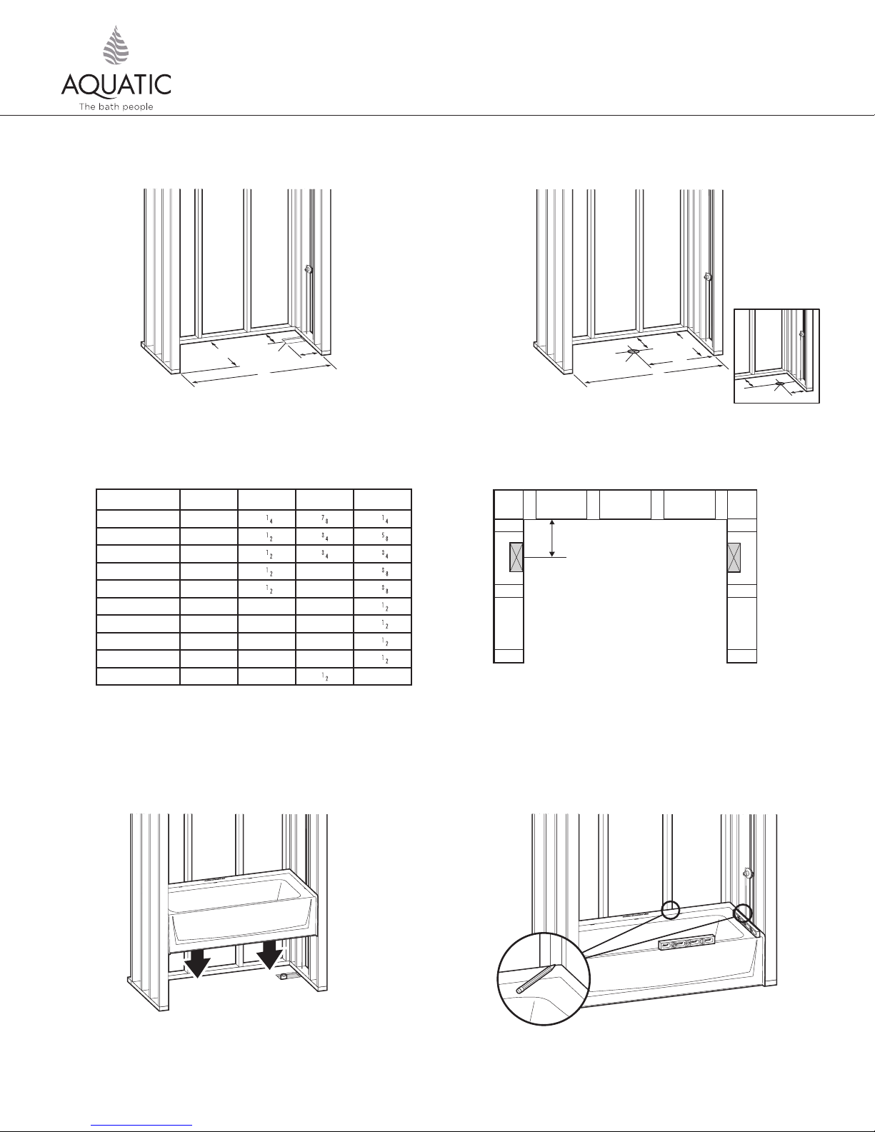
Check dimensions. For tub-showers, refer to Diagram 1A; for showers, refer to Diagram 1B.
NOTE: If you’re adding additional accessories such as a grab bar–additional framing may be needed for support.
Models A B C D
6030CT/CTM 60” 311⁄4
6030CTMIN/CTMM 60” 311⁄2
6032CTMIN/CTMM 60” 331⁄2
6036CT/CTM 60” 371⁄2
6042CT/CTM 60” 431⁄2
3232CPAN 32” 32” 16” 151⁄2
3636CPAN 36” 36” 18” 171⁄2
4834CPAN 48” 34” 24” 161⁄2
6034CPAN 60” 34” 30” 161⁄2
6030CPAN 60” 30” 81⁄2
Pre-install unit to ensure framing pocket is plumb, square and a level
installation can be achieved (see steps 3 through 9).
Adjust framing as needed – Shim where necessary.
C
AA
AA
” 27⁄8
” 23⁄4
” 23⁄4
” 2 173⁄8
” 2 203⁄8
” 141⁄4
” 145⁄8
” 153⁄4
” 14”
32
”
C
”
”
”
”
”
”
”
”
Additional stud may be required for vertical backwall flange.
Stud @ 7
for easier installation.
7
⁄8” CL from back, on both sides. Stud can be turned
77⁄8"
DD
B
B
C
6"Dia.
L
C
AA
DD
CC
6"Dia.
*Review Tech Data at a2bath.com for more detail.
Note: 6030CTS is shown for illustrational purposes.
4
Lift and place the base into framing.
Customer Service (800) 945-2726 • www.aquaticbath.com
5
Level and mark all sides. Front apron should be firmly on the floor.
— 3 —
Page 4
INSTALLATION PROCEDURE, CONT.
Installation Instructions
4-Piece A2 Composite Shower System Models
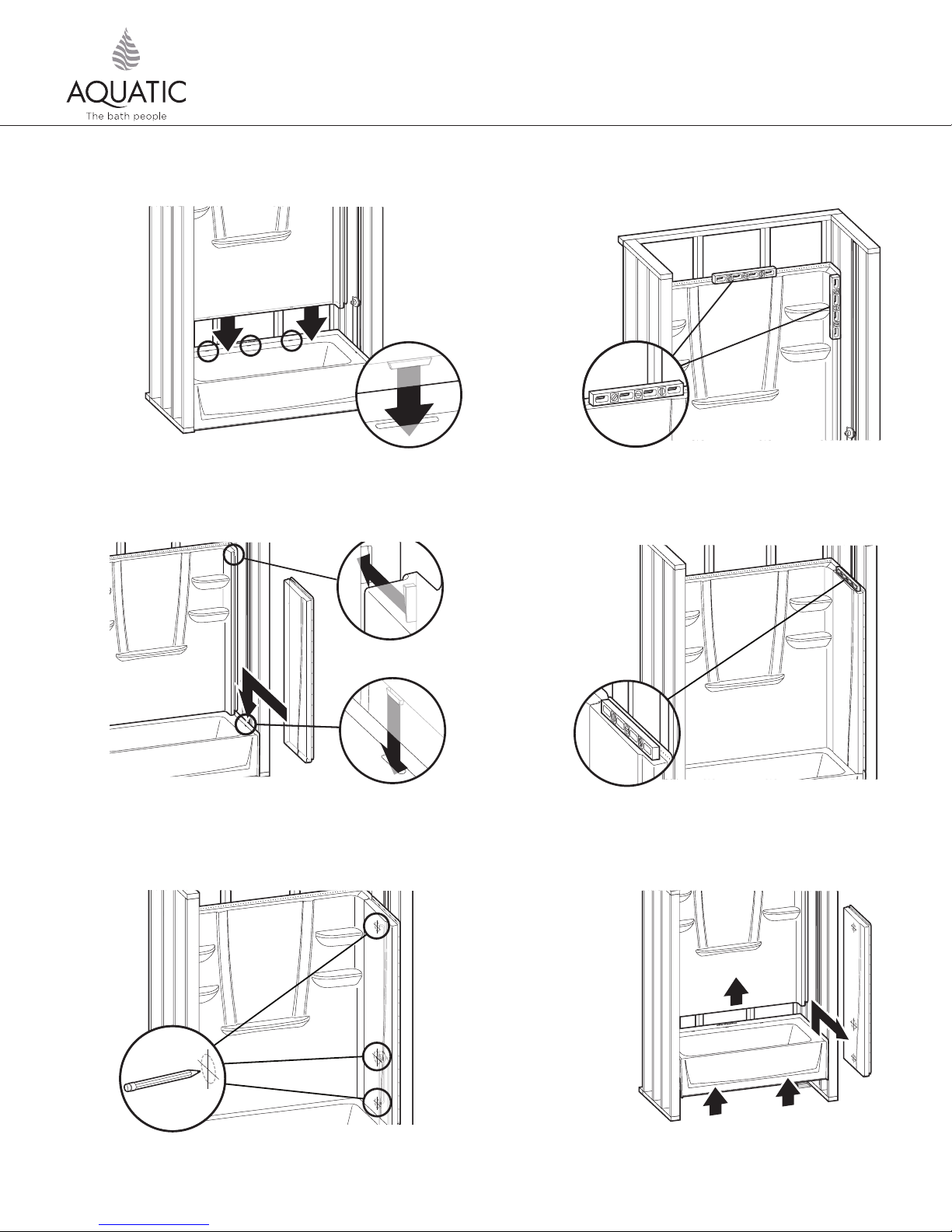
6
Lift and place the back wall, making sure locking tabs are engaged.
8
7
Level back wall vertically & horizontally. Shim if necessary.
9
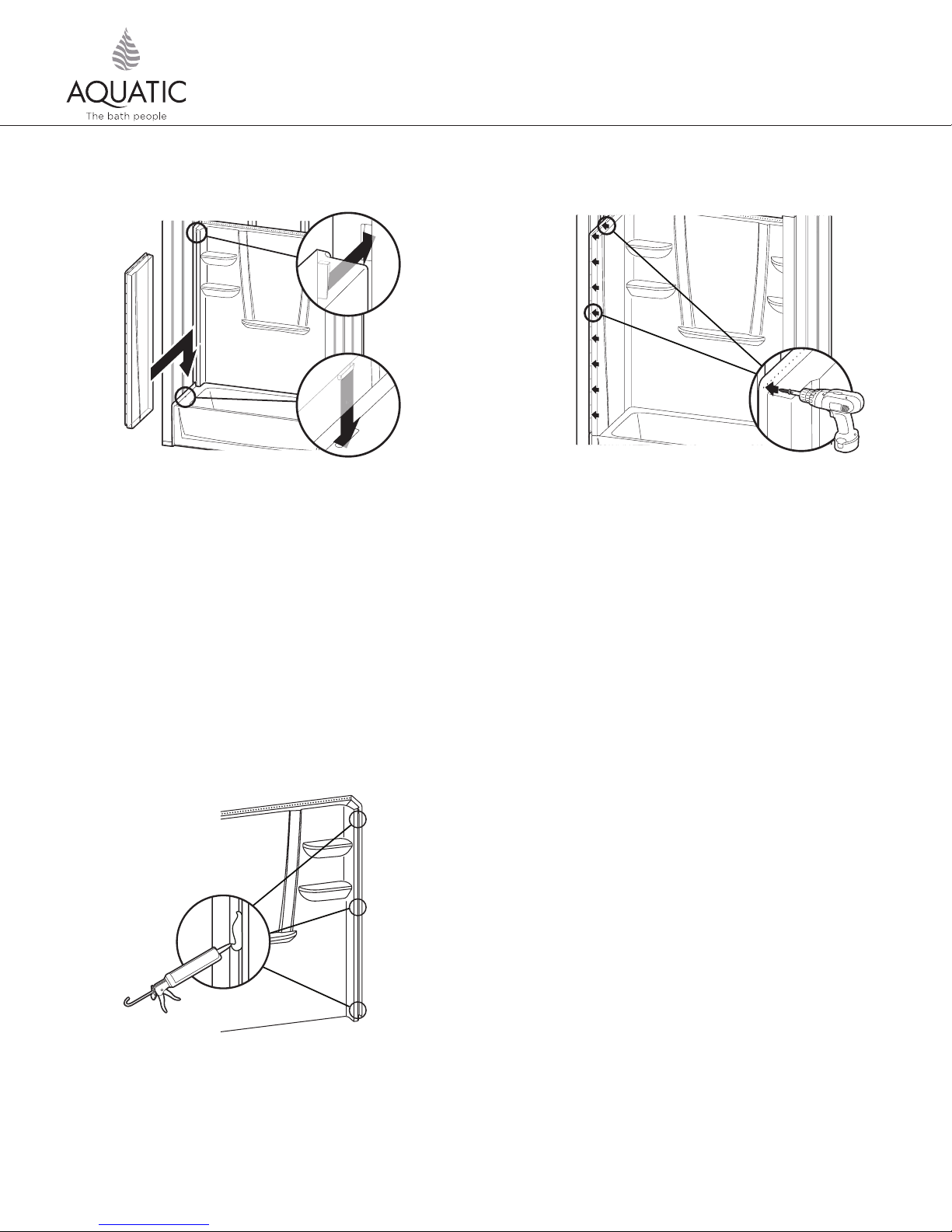
Slide right side wall into position. Be sure locking mechanism is engaged.
10
Customer Service (800) 945-2726 • www.aquaticbath.com
Check for level. Shim if necessary.
11
— 4 —
Page 5
INSTALLATION PROCEDURE, CONT.
Installation Instructions
4-Piece A2 Composite Shower System Models
12
Using a hole saw (fine tooth or abrasive grit cutting edge), make necessary
openings for filler and valves, drilling from inside (smooth side) out.
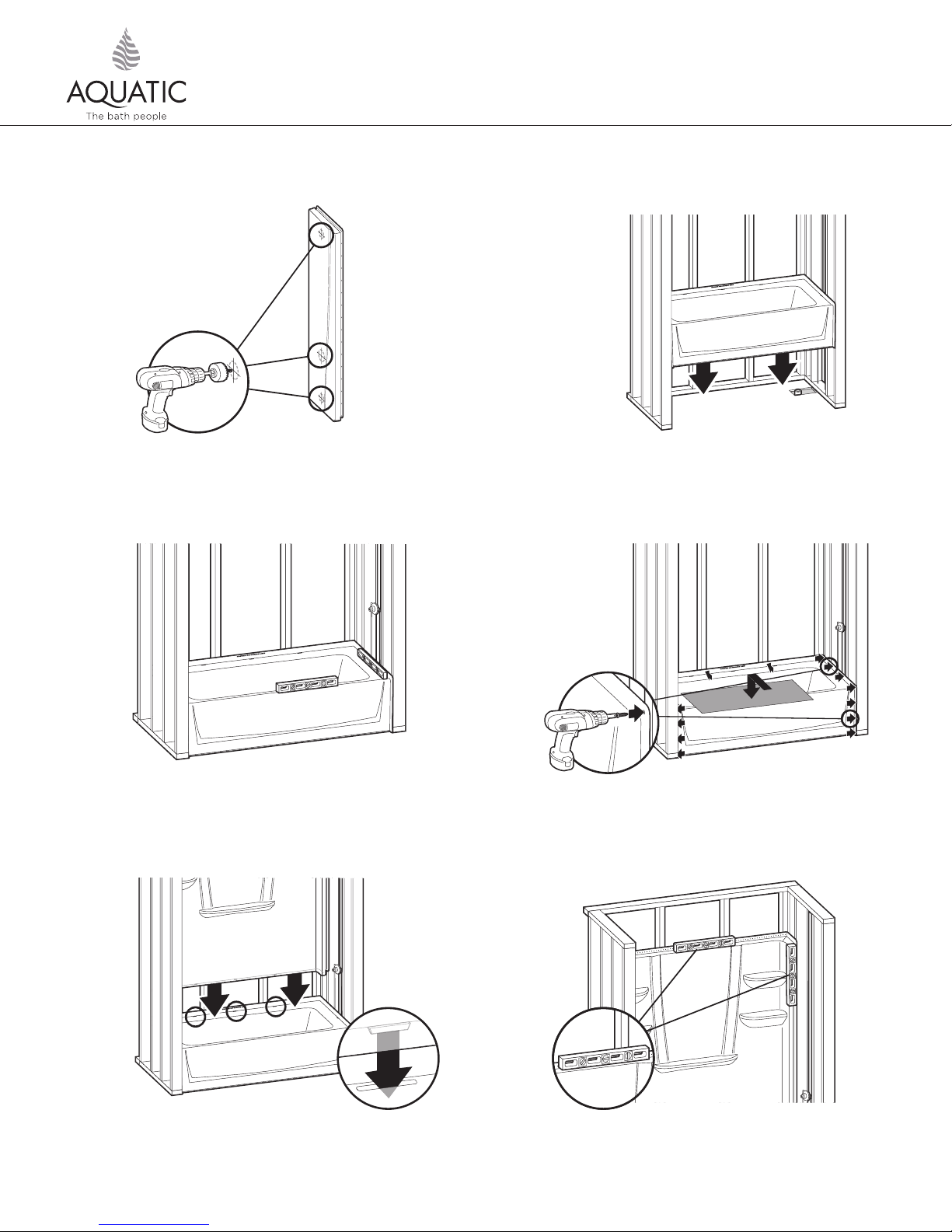
14
13
Install drain assembly per manufacturer’s instructions. Place base into
framing pocket.
15
Level lengthwise and widthwise using 3 ft. (915mm) level
by shimming if necessary. The unit must be set level.
16
Lift and place back wall, making sure locking tab is engaged.
Customer Service (800) 945-2726 • www.aquaticbath.com
Pre-drill horizontal flanges along top of base section and fasten into each
corresponding stud. Pre-drill both (vertical) side flanges and fasten to side
studs 8” (200mm) on center. Place cardboard to protect finish.
17
Level back wall vertically & horizontally. Shim if necessary.
— 5 —
Page 6
INSTALLATION PROCEDURE, CONT.
Installation Instructions
4-Piece A2 Composite Shower System Models
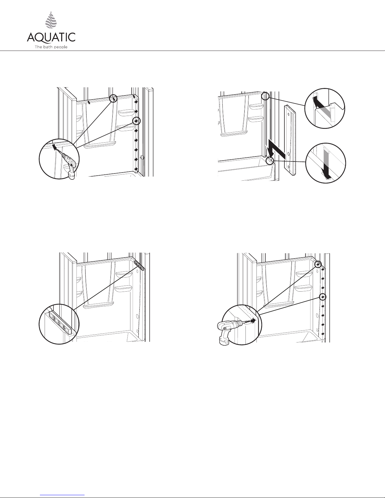
18
Fasten flanges along top of back wall with fasteners of choice (see PreInstallation Planning #12) into each corresponding stud. Pre-drill both
(vertical) side flanges and nail fasten to side studs 8” (200mm) on center.
NOTE: A stud should be added if adding accessories. Must have at least 1
fire block to secure vertically.
20
19
Slide right side wall into position. Be sure locking mechanism is engaged.
NOTE: Finish caulking is not required, however, if using caulk, weep channel
must remain clear of obstruction to allow for proper drainage of the unit.
21
Check for level. Shim if necessary.
NOTE: To accommodate any stud variation, you may have to add a bead of
waterproof adhesive such as 100% silicone to eliminate any potential free play.
*See illustration 1A.
Customer Service (800) 945-2726 • www.aquaticbath.com
Fasten flanges along top of right side wall with fasteners of choice
(see Pre-Installation Planning #12) into each corresponding stud. Fasten
side (vertical) flanges to side studs 8” (200mm) on center.
— 6 —
Page 7
INSTALLATION PROCEDURE, CONT.
Installation Instructions
4-Piece A2 Composite Shower System Models
22
Slide left side wall into position. Be sure locking mechanism is engaged.
NOTE: To accommodate any stud variation, you may have to add a bead of
waterproof adhesive such as 100% silicone to eliminate any potential free play.
*See illustration 1A.
23
Fasten flanges along top of left side wall with fasteners of choice
(see Pre-Installation Planning #12) into each corresponding stud.
Fasten side (vertical) flanges to side studs 8” (200mm) on center.
NOTE: Finish caulking is not required, however, if using caulk,
weep channel must remain clear of obstruction to allow for proper
drainage of the unit.
1A
*If free play is observed in sidewalls of unit, a small amount of 100%
silicone can be added to location in question.
Customer Service (800) 945-2726 • www.aquaticbath.com
— 7 —
Page 8

Installation Instructions
4-Piece A2 Composite Shower System Models
CLEAN-UP
CAUTION: SOME CLEANING PRODUCTS ARE NOT SUITABLE FOR USE. READ ALL LABELS CAREFULLY. DO NOT USE if labels say heat or solvent
based cleaning fluids.
NOTE: Do not remove warranty/maintenance adhered label. Warranty/User maintenance label must be left for occupant (Required by
ANSIZ124).
1. To prevent staining, remove all debris before plumbing leak test. Drain and wipe clean immediately after the inspection process. Use
sponge with warm water and liquid detergent. Rinse, drain and wipe clean. Do not use abrasive cleansers that might mar, dull or scratch
the finish such as scouring powders, steel wool, metal scrapers, or sandpaper.
2. If drywall mud or plaster gets on your fixture, it may be carefully removed with a wooden scraper. Roofing tar or paints may be removed
with rubbing alcohol or paint thinner. Lacquer thinner should never be used on the fixture.
3. Plaster and latex paint may be removed with warm water, liquid detergent and brittle brush or plastic scraper. Do not use metal scraper
or utensil to remove plaster or paint from finish.
4. Dull areas and light scratches can be restored to high gloss by buffing with a soft cloth with white or cream-colored automotive rubbing
compound, followed by the application of coat or good quality white automotive polish (or similar) and buff with a soft cloth. DO NOT
WAX standing surfaces of the unit bottom (this includes textured, slip resistant standing surfaces), which could result in greater risk of
slipping and personal injury.
5. Major gouges require professional repair.
6. See user maintenance instructions and label for more details.
USER MAINTENANCE INSTRUCTIONS
IMPORTANT! Use only recommended cleaners and procedures described herein. Use of other materials and methods may damage your bath
fixture and void the warranty.
1. For normal cleaning, never use abrasive cleaners such as scouring powders or pads, steel wool, scrapers, sandpaper or anything else
that could scratch or dull the surface of your fixture. Use warm water and liquid detergents or non-abrasive cleansers, such as Soft Scrub
Gel or Comet Gel. Read all labels carefully and DO NOT USE if they say “not suitable for use with fiberglass.”
2. To keep your Aquatic fixture sparkling clean, apply a coat of good quality automotive paste wax or polish and buff to a high shine with
a soft cloth or towel. Repeat every six months for easier cleaning and long lasting protection. DO NOT WAX standing surfaces of the unit
bottom (this includes textured, slip resistant standing surfaces), which could result in greater risk of slipping and personal injury.
3. To restore a scratched or dull unit, use an automotive polishing compound applied with a clean cotton rag. Rub scratches and dull areas
vigorously. Wipe off residues. Follow with automotive wax treatment described above. DO NOT WAX standing surfaces of the unit
bottom (this includes textured, slip resistant standing surfaces), which could result in greater risk of slipping and personal injury.
4. To remove adhesive, try 3-M® natural cleaner, De-Solv-It® or similar materials. If residues remain, saturate small white cotton rag with nail
polish remover and rub vigorously until the adhesive dissolves and disappears. These solvents are highly flammable and must be used
sparingly and with caution. Do not allow solvent to go down the drain. Make sure not to contact plastic drain grates or other synthetic
materials.
5. Rubber mats: If you use rubber “anti-skid” mat, make sure to remove it from the unit after each use to avoid harm to the surface finish.
6. Hard Water: Water in certain regions, if not wiped up after bathing/showering, may cause fading of some Aquatic fixture colors.
This is a natural occurrence beyond Aquatic’s control and Aquatic is not responsible for any fading caused from hard water.
(See Warranty)
CAUTION: When using any cleaning or polishing materials, make sure to read and follow all package instructions carefully. Wear rubber
gloves at all times and avoid contact with eyes, skin, clothing, rugs and furnishings. Make sure all residues are rinsed off thoroughly.
LITID1360
Customer Service (800) 945-2726 • www.aquaticbath.com
— 8 —
Page 9

Instrucciones de instalación
Modelos de sistema de regadera de 4 piezas de resina compuesta
INFORMACIÓN GENERAL DE INSTALACIÓN
Gracias por elegir Aquatic. Para asegurarse de obtener el mejor funcionamiento del mueble Aquatic, lea y siga las
instrucciones y precauciones. Revise cuidadosamente el nuevo mueble Aquatic para asegurarse de que no se haya dañado en
el envío. Si encuentra algún daño, informe de inmediato al proveedor. Si el mueble Aquatic está dañado, no debe instalarlo
bajo ninguna
circunstancia. Aquatic y el distribuidor de Aquatic no se responsabilizarán por los costos de desinstalación o reinstalación del
mueble si debe reemplazarse debido a que se instaló dañado. No realice modificaciones en el mueble Aquatic, ya que esto
podría afectar negativamente la seguridad y el funcionamiento del mismo y anulará la garantía. No cumplir con cualquiera
de las instrucciones de instalación y precauciones puede anular la garantía. Si tiene alguna pregunta sobre la instalación y el
mantenimiento del mueble Aquatic, póngase en contacto con el Servicio técnico al 1-800-945-2726.
Elementos incluidos:
2
A
Tina-regadera
Herramientas necesarias
Taladro
Broca de taladro
de 3/16”
Punta de
destornillador Phillips
Sierra perforadora
tornillos autorroscantes con
cabeza con arandela de 10x11⁄2”
o clavos galvanizados para techo de 11⁄2”
Customer Service (800) 945-2726 • www.aquaticbath.com
Regadera
Martillo Nivel
Cinta
métrica
— 9 —
Anteojos de
seguridad
masilla/sellador para realizar la instalación.
NOTA: NO se necesita
Page 10

Instrucciones de instalación
Modelos de sistema de regadera de 4 piezas de resina compuesta
ANTES DE EMPEZAR LA INSTALACIÓN, LEA COMPLETAMENTE TODAS LAS INSTRUCCIONES.
PLANIFICACIÓN PREVIA A LA INSTALACIÓN
1. Revise los documentos del trabajo y las dimensiones preliminares de Aquatic. Verifique todas las dimensiones clave en relación con
las condiciones de trabajo reales. DEBE ASEGURARSE DE QUE LAS DIMENSIONES PRELIMINARES SEAN CORRECTAS Y ESTÉN A
ESCUADRA.
2. Ubique los montantes según sea necesario y, si se debe realizar una remodelación, agregue montantes en cada extremo para proveer
una superficie vertical para la colocación de los clavos para los rebordes laterales para clavos del mueble Aquatic.
2
A
3. Asegúrese de que la cavidad con el armazón de montaje sea del tamaño adecuado, esté a escuadra y vertical. Revise también que el
piso esté nivelado. Puede necesitar usar cuñas entre la estructura del montante y el mueble.
4. NO instale el producto directamente sobre un envigado descubierto del piso. El producto no debería necesitar ningún apoyo adicional
si el contrapiso está a escuadra y a nivel con el armazón de montaje. Si el contrapiso no está a nivel, puede necesitar usar cuñas o
colocar material de relleno y cimentación para proveer una superficie de apoyo adicional.
5. Si se requiere usar una cavidad del armazón de montaje resistente al fuego, se debe colocar el material de acabado aprobado antes
de instalar la unidad, de acuerdo con los requisitos de seguridad contra incendio del código de construcción local y/o las Normas
mínimas de propiedad de la FHA y el HUD. NOTA: La cavidad del armazón de montaje terminada debe tener las dimensiones interiores
que se muestran en el diagrama para poder instalar la unidad.
6. Se recomienda usar yeso industrial, mezcla de mortero o lechada liviana (en adelante, denominados “materiales de relleno y
cimentación”) para proveer un soporte inferior más firme.
7. Provea una apertura en el piso de 6” (150 mm) para la conexión de desagüe y un IPS de 2” (50 mm).
8. Para garantizar la instalación correcta de la unidad, se debe cumplir con todos los códigos de plomería y construcción locales. Los
códigos de construcción locales son distintos para cada región, y es su responsabilidad asegurarse de que todas las instalaciones de
plomería estén completas y en conformidad con el código pertinente.
9. Para evitar obstrucciones, asegúrese de que las líneas de suministro y la tubería de las válvulas no sobresalgan en la cavidad del
armazón de montaje durante el proceso de instalación. Además, el caño de desagüe no debe sobresalir del nivel del piso antes de la
instalación.
10. En el lado interior del panel para las tuberías de agua (wet wall) de la unidad, anote la ubicación del codo de suministro y la válvula
mezcladora. (Consulte “Conectores de la tina y regadera” debajo.)
11. Para evitar raspar la unidad durante la instalación, cubra el piso de la unidad con un cartón u otro material.
12. Sujetadores para: Marco de madera: clavos galvanizados de 1 1⁄2
Muros de concreto o bloque: clavos para concreto de 1” y pistola para clavos. Paredes con montantes de acero (calibre 18): perfore
los rebordes y los montantes con una broca de carburo de 5⁄32
una perforación preliminar, cualquiera sea el sujetador que use.use.
13. Si va a instalar una puerta de regadera, consulte las instrucciones de instalación del fabricante de la puerta de la regadera para tener
en cuenta cualquier consideración especial.
14. NOTA: En algunas regiones, la normativa especifica dimensiones mínimas para aberturas de puertas y puede requerirse el uso de
puertas de vaivén para las cabinas de regaderas. (Las puertas corredizas pueden no proveer una apertura del ancho requerido.)
15. El modelo 3232CS no lleva el sello UPC y no está aprobada por algunos códigos de plomería municipales debido a sus dimensiones
interiores. Revise los códigos de construcción de su localidad.
Conectores de la tina y regadera: Si va a colocar conectores en la tina o en la regadera, desde puntos de referencia estables (montantes de
la pared, piso) mida la ubicación de la salida de agua y las válvulas. Anote las medidas:
Tubería de llenado de la tina: ____________________________________ Válvula: ______________________________________
Brazo de regadera: _____________________________________________ Válvula: ______________________________________
(Marque las dimensiones únicamente si el brazo de la regadera conecta al área de la pared del mueble de baño.)
Customer Service (800) 945-2726 • www.aquaticbath.com
” o tornillos autorroscantes con cabeza con arandela de #10 x 1 1⁄2
” y use tornillos para metal de #12 x 1”. NOTA: Debe realizar siempre
— 10 —
”.
Page 11

Instrucciones de instalación
Modelos de sistema de regadera de 4 piezas de resina compuesta
PROCEDIMIENTO DE INSTALACIÓN
1A 1B
2
A
Verifique las dimensiones. Para tinas-regaderas, consulte el Diagrama 1A; para regaderas, consulte el Diagrama 1B.
NOTA para 1B: Si debe agregar accesorios adicionales, como una barra de seguridad, puede necesitar usar un armazón de montaje adicional como soporte.
2
Instale de manera provisoria la unidad para asegurarse de que la cavidad
del armazón de montaje esté a escuadra y vertical y que se puede realizar
una instalación nivelada (consulte los pasos 3 al 9).
Modelos A B C D
6030CT/CTM 60” 311⁄4
6030CTMIN/CTMM 60” 311⁄2
6032CTMIN/CTMM 60” 331⁄2
6036CT/CTM 60” 371⁄2
6042CT/CTM 60” 431⁄2
3232CPAN 32” 32” 16” 151⁄2
3636CPAN 36” 36” 18” 171⁄2
4834CPAN 48” 34” 24” 161⁄2
6034CPAN 60” 34” 30” 161⁄2
6030CPAN 60” 30” 81⁄2
DD
C
B
B
6"x12"
C
AA
AA
6"Dia.
DD
B
B
C
C
AA
DD
CC
6"Dia.
3
” 27⁄8
” 23⁄4
” 23⁄4
” 2 173⁄8
” 2 203⁄8
” 141⁄4
” 145⁄8
” 153⁄4
” 14”
”
”
”
”
”
”
”
”
”
Levante y coloque la base en el armazón de montaje.
Realice los ajustes necesarios en el armazón de montaje y use cuñas donde
sea necesario.
4
Nivele y marque todos los lados. El panel frontal deben apoyarse
firmemente sobre el piso.
Customer Service (800) 945-2726 • www.aquaticbath.com
5
Levante y coloque el panel posterior, asegurándose de que se
enganchen las pestañas de sujeción.
— 11 —
Page 12

Instrucciones de instalación
Modelos de sistema de regadera de 4 piezas de resina compuesta
PROCEDIMIENTO DE INSTALACIÓN, CONTINUACIÓN
2
A
6
7
Nivele el panel posterior en sentido horizontal y vertical. Use cuñas
si es necesario.
8 9
Deslice el panel lateral derecho hasta colocarlo en posición. Asegúrese de
que se enganche el mecanismo de sujeción.
Verifique que la unidad quede nivelada. Use cuñas si es necesario.
10
Retire el panel posterior, el panel lateral derecho y la base.
Customer Service (800) 945-2726 • www.aquaticbath.com
Marque la ubicación de las tuberías en el panel de la regadera. Consulte
“Conectores de la tina y regadera” para obtener las medidas.
11
Con una sierra perforadora (de diente fino o con borde abrasivo) realice
las aberturas necesarias para la tubería de llenado y las válvulas,
perforando desde adentro (el lado liso) hacia fuera.
— 12 —
Page 13

Instrucciones de instalación
Modelos de sistema de regadera de 4 piezas de resina compuesta
PROCEDIMIENTO DE INSTALACIÓN, CONTINUACIÓN
12A 12B
Instale el montaje de desagüe de acuerdo a las instrucciones del fabricante. Si lo desea, coloque material de relleno y cimentación. Si va a aplicar materiales
de relleno y cimentación, siga estas instrucciones: Mezcle el material de relleno y cimentación. Coloque tres o cuatro montículos de mezcla en el contrapiso
alrededor del agujero de desagüe, pero a cierta distancia de éste. Los montículos deben tener la altura suficiente para que cuando se coloque la unidad la
mezcla se aplaste y se esparza. (Para la tina/regadera, consulte el diagrama 12A. Para la regadera, consulte el diagrama 12B.)
13 14
2
A
Coloque la base en la cavidad del armazón de montaje.
15
Perfore previamente los rebordes horizontales en la parte superior
de la sección de la base y clave o atornille a todos los montantes
correspondientes. Perfore previamente los dos rebordes laterales (verticales)
y clave o atornille a los montantes laterales de 8” (200 mm) en el centro.
Coloque un cartón para proteger el acabado.
Customer Service (800) 945-2726 • www.aquaticbath.com
Nivele bien dando unos ligeros golpes. Para nivelar la unidad, use un
nivel de 3 pies (915 mm) a lo largo y a lo ancho de la unidad y, según
lo necesite, acuñe o presione para aplanar los materiales de relleno y
cimentación. La unidad debe quedar nivelada.
16
Levante y coloque el panel posterior, asegurándose de que se enganche la
pestaña de sujeción.
— 13 —
Page 14

Instrucciones de instalación
Modelos de sistema de regadera de 4 piezas de resina compuesta
PROCEDIMIENTO DE INSTALACIÓN, CONTINUACIÓN
17 18
2
A
Nivele el panel posterior en sentido horizontal y vertical. Use cuñas
si es necesario.
19
Deslice el panel lateral derecho hasta colocarlo en posición. Asegúrese de
que se enganche el mecanismo de sujeción. NOTA: No se requiere usar
sellado/masilla, pero, si lo hace, asegúrese de no obstruir los canales de
escurrimiento para que la unidad desagote de manera apropiada.
Clave o atornille los rebordes de toda la parte superior del panel posterior
con los sujetadores que prefiera (consulte el punto 12 de Planificación
previa a la instalación) a cada montante correspondiente. Perfore
previamente los dos rebordes laterales (verticales) y ajuste con clavos a los
montantes laterales de 8” (200 mm) en el centro. NOTA: Si va a colocar
accesorios adicionales, debe agregar otro montante. Debe tener como
mínimo 1 cortafuegos que debe asegurarse en sentido vertical.
20
Verifique que la unidad quede nivelada. Use cuñas si es necesario.
Customer Service (800) 945-2726 • www.aquaticbath.com
— 14 —
Page 15

Instrucciones de instalación
Modelos de sistema de regadera de 4 piezas de resina compuesta
PROCEDIMIENTO DE INSTALACIÓN, CONTINUACIÓN
2
A
21
Clave o atornille los rebordes de toda la parte superior del panel
lateral derecho con los sujetadores que prefiera (consulte el punto
12 de Planificación previa a la instalación) a todos los montantes
correspondientes. Clave o atornille los rebordes laterales (verticales)
a los montantes laterales de 8” (200 mm) en el centro.
23
22
Deslice el panel lateral izquierdo hasta colocarlo en posición. Asegúrese de
que se enganche el mecanismo de sujeción. NOTA: No se requiere usar
sellado/masilla, pero, si lo hace, asegúrese de no obstruir los canales de
escurrimiento para que la unidad desagote de manera apropiada.
Clave o atornille los rebordes de toda la parte superior del panel
lateral izquierdo con los sujetadores que prefiera (consulte el punto
12 de Planificación previa a la instalación) a todos los montantes
correspondientes. Clave o atornille los rebordes laterales (verticales) a los
montantes laterales de 8” (200 mm) en el centro.
Customer Service (800) 945-2726 • www.aquaticbath.com
— 15 —
Page 16

Instrucciones de instalación
Modelos de sistema de regadera de 4 piezas de resina compuesta
LIMPIEZA
PRECAUCIÓN: Algunos productos de limpieza no son apropiados para el mueble. Lea cuidadosamente la etiqueta del producto. NO USE si
la etiqueta indica que el producto es un líquido limpiador con solventes o que actúa con calor. NOTA: No retire la etiqueta adherida de
garantía/mantenimiento. La etiqueta de garantía/mantenimiento del usuario debe dejarse colocada para el ocupante (requisito ANSIZ124).
1. Quite toda la suciedad antes de realizar la inspección de plomería para verificar que no haya filtraciones. Desagote y limpie con un
trapo inmediatamente después de realizar el proceso de inspección. Use una esponja con agua tibia y detergente líquido. Enjuague,
vacíe y limpie con un trapo. No use limpiadores abrasivos que puedan estropear, quitar brillo o rayar el acabado de la unidad, como
polvos desengrasantes, lana de acero, espátulas de metal y papel de lija.
2
A
2. Si quedan restos de tablarroca o yeso pegados en el mueble, puede quitarlos con cuidado con una espátula de madera. Los restos de
brea o pintura pueden quitarse frotando alcohol o diluyente de pintura. Nunca debe usar diluyente de laca en el mueble.
3. Puede quitar los restos de yeso y pintura al látex con agua tibia, detergente líquido y un cepillo suave o espátula de plástico. No use
una espátula metálica ni otro elemento de metal para quitar el yeso o la pintura del acabado.
4. Para devolver el alto brillo a la zonas opacas y borrar los rayones leves, con un paño suave, lustre la unidad con pasta para pulir
para autos color crema o blanco y después aplique una capa de pulidor blanco para autos (o similar) de buena calidad y lustre
con un paño suave. NO USE CERA sobre las superficies para pararse de la base de la unidad (incluye las superficies texturizadas
antiderrapantes), ya que aumenta significativamente el riesgo de resbalarse y sufrir lesiones.
5. Se requiere un profesional para reparar rayones más profundos.
6. Para más información, lea las instrucciones y la etiqueta de mantenimiento para el usuario.
INSTRUCCIONES DE MANTENIMIENTO PARA EL USUARIO
IMPORTANTE: Use solo los productos de limpieza recomendados y los procedimientos que se describen en este documento. El uso de otros
materiales y métodos puede dañar el mueble de baño y anulará la garantía.
1. Para la limpieza normal, nunca use limpiadores abrasivos como polvos o paños desengrasantes, lana de acero, espátula, papel de
lija ni ningún otro producto que pueda rayar o quitar al brillo de la superficie del mueble. Use agua tibia y detergentes líquidos o
limpiadores no abrasivos, como Soft Scrub Gel o Comet Gel. Lea todas las etiquetas y NO USE si la etiqueta indica que el producto no
es apto para usarse con fibra de vidrio.
2. Para mantener el mueble Aquatic impecablemente limpio, aplique una capa de cera o pulidor para autos de buena calidad y lustre
hasta sacar brillo con un paño o toalla suave. Repita cada seis meses para facilitar la limpieza y proteger la unidad por mucho tiempo.
NO USE CERA sobre las superficies para pararse de la base de la unidad (incluye las superficies texturizadas antiderrapantes), ya que
aumenta significativamente el riesgo de resbalarse y sufrir lesiones.
3. Para devolver el brillo a las zonas opacas y borrar rayones, con un poco de algodón limpio, aplique un compuesto para pulir autos.
Frote con fuerza las partes con rayones y sin brillo. Quite los residuos. Aplique el tratamiento con cera para autos que se describe
arriba. NO USE CERA sobre las superficies para pararse de la base de la unidad (incluye las superficies texturizadas antiderrapantes),
ya que aumenta significativamente el riesgo de resbalarse y sufrir lesiones.
4. Para quitar restos de pegamento use los productos de limpieza 3-M® Natural Cleaner, De-Solv-lt® o similares. Si aún quedan restos,
empape un poco de algodón blanco con quitaesmalte para uñas y frote con fuerza hasta que se disuelva y desaparezca el pegamento.
Estos solventes son muy inflamables y deben usarse cono moderación y precaución. No deje que caiga solvente en el desagüe.
Asegúrese de que el solvente no entre en contacto con las rejillas plásticas del desagüe ni con otros materiales sintéticos.
5. Alfombras de goma: Si usa una alfombra de goma antiderrapante, asegúrese de retirarla de la unidad cada vez que termine de usarla
para evitar que se dañe la superficie.
6. Agua dura: El agua de ciertas regiones, si no se seca después usar la unidad, puede quitar el color del mueble Aquatic. Este es un
proceso natural fuera del control de Aquatic y Aquatic no se responsabiliza de ningún tipo de pérdida de color de la unidad por el
efecto del agua dura. (Consulte la garantía)
PRECAUCIÓN: Al usar productos de limpieza o pulido, asegúrese de leer y seguir todas las instrucciones. Use guantes de goma en todo
momento y evite el que el producto entre en contacto con los ojos, la piel, la ropa, alfombras y el mobiliario. Asegúrese de enjuagar bien
los restos del producto.
Customer Service (800) 945-2726 • www.aquaticbath.com
— 16 —
Page 17

Instructions d’installation
Modèles de système de douche en composite A
INFORMATION GÉNÉRALE POUR L’INSTALLATION
Nous vous remercions d’avoir choisi Aquatic. Pour assurer la performance maximale de votre appareil Aquatic, veuillez lire et suivre les
instructions et mises en garde. Inspectez attentivement le nouvel appareil Aquatic à la recherche de tout dommage survenu en cours de
transport. Dans l’éventualité d’un tel dommage, signalez-le immédiatement à votre fournisseur. Un appareil Aquatic endommagé ne doit
être installé en aucune circonstance. Ni Aquatic ni son distributeur commercial ne seront tenus responsables des coûts de démontage ou de
réinstallation si un remplacement s’avère nécessaire en raison de l’installation d’un appareil endommagé.
N’apportez pas de modifications à l’appareil Aquatic. Cela pourrait compromettre la sécurité et la performance de l’appareil Aquatic et
annuler la garantie. Tout non-respect des instructions d’installation et mises en garde peut annuler la garantie. Pour des questions concernant
l’installation et l’entretien de l’appareil Aquatic, communiquez avec les services techniques au 1-800-945-2726.
Articles inclus
2
en 4 pièces
Baignoire/douche Douche
Outils nécessaires
Perceuse
Mèche de 4,76 mm
(3/16 po)
Embout de
tournevis Phillips
Scie cylindrique
Vis à tête à embase
autotaraudeuse n° 10de 4 cm
(1 ½ po) OU clous à toiture
galvanisés de 4 cm (1 ½ po)
Customer Service (800) 945-2726 • www.aquaticbath.com
Marteau Niveau
Ruban à mesurer
— 17 —
Lunettes
de sécurité
REMARQUE : AUCUN produit de
calfeutrage n’est nécessaire
pour cette installation.
Page 18

Instructions d’installation
Modèles de système de douche en composite A
VEUILLEZ LIRE EN ENTIER TOUTES LES INSTRUCTIONS D’INSTALLATION AVANT DE COMMENCER L’INSTALLATION.
PLANIFICATION AVANT L’INSTALLATION
1. Prenez connaissance de ce guide ainsi que des dimensions pour l’installation de l’unité Aquatic, vérifiez toutes les principales dimensions
sur le lieu de l’installation. ASSUREZ-VOUS QUE LES DIMENSIONS POUR L’INSTALLATION SONT APPROPRIÉES ET À ANGLE DROIT.
2. Localisez les montants selon les besoins et, dans le cas d’un remodelage, ajoutez si nécessaire des montants à chaque extrémité pour
fournir une surface de clouage verticale aux rebords de clouage de l’appareil Aquatic.
3. Vérifiez que l’encadrement fourni est de bonne taille, à angle droit et d’aplomb; vérifiez que la surface au sol est plane. Il est possible
de devoir utiliser des cales entre les montants de l’encadrement et l’appareil.
4. N’INSTALLEZ PAS le produit au dessus de solives de plancher apparentes. Le produit ne devrait pas nécessiter de soutien additionnel si le
faux plancher est à angle droit et de niveau avec la charpente. Il peut être nécessaire d’ajouter des cales ou un matériau de fondation
comme support additionnel si le faux plancher est inégal.
5. Si un encadrement pare-feu est nécessaire, le matériel de finition approuvé doit être mis en place avant l’installation de l’unité pour
se conformer aux exigences de sécurité incendie du code de construction local et/ou aux normes de propriété minimum FHA/HUD.
REMARQUE : Les dimensions intérieures finies de l’encadrement doivent correspondre aux dimensions indiquées sur le diagramme de
construction brute pour permettre l’installation de l’unité.
6. Il est recommandé d’utiliser un plâtre industriel, un mortier ou un coulis ultra léger (désignés sous le nom de matériaux de fondation) pour
assurer un meilleur support du fond.
2
en 4 pièces
7. Assurez-vous d’avoir une ouverture de plancher de 150 mm (6 po) pour les raccords IPS et de vidange de 50 mm (2 po).
8. Pour garantir une installation adéquate, assurez-vous que toute la plomberie est complète et conforme au code. Les codes du bâtiment
locaux varient selon le lieu et vous êtes responsable de vous assurer que la plomberie est complète et conforme au code.
9. Pour éviter toute obstruction, assurez-vous que l’arrivée d’eau et les robinets de drainage ne saillent pas dans l’encadrement pendant
l’installation. De plus, la tuyauterie de vidange ne doit pas excéder le niveau du plancher avant l’installation.
10. Prenez note de l’emplacement du coude d’amenée d’eau et du robinet mitigeur à l’intérieur de la paroi de plomberie du produit. (Voir
« Raccords de baignoire et de douche » ci-dessous.)
11. Afin d’éviter des éraflures lors de l’installation, recouvrez le plancher de l’unité à l’aide d’un morceau de carton ou d’un autre matériau
de protection.
12. Pièces de fixation pour : encadrement en bois : clous de toiture galvanisés de 4 cm (1 ½ po) ou vis à tôle autotaraudeuse à tête rondelle
nº 10 de 4 cm (1 ½ po). Murs en béton ou briques : clous de 2,5 cm (1 po) et marteau pour béton. Montants en acier (calibre 18)
: percez les brides et montants à l’aide d’une mèche au carbure de 0,4 cm (5⁄32
REMARQUE : Prépercez toujours, quelle que soit la fixation utilisée.
13. Si vous installez une porte de douche, suivez les instructions particulières d’installation du fabricant.
14. REMARQUE : si le Code du bâtiment local exige une ouverture minimum, il pourrait être nécessaire d’installer des portes de douche à
charnières. (Les portes coulissantes peuvent ne pas permettre une ouverture suffisante).
15. 3232CS n’a pas de code UPC et n’est pas approuvé par certains codes de plomberie municipaux en raison des dimensions internes.
Vérifiez votre code du bâtiment local.
Raccords de baignoire et de douche : En présence de raccords de montage sur la baignoire ou la douche, mesurez l’emplacement du bec et
des robinets à partir de points de référence stable (montants du mur arrière, plancher). Inscrivez les mesures :
po) et utilisez des vis à tôle nº 12 de 2,5 cm (1 po).
Robinet de baignoire : _______________________________________ Vanne : _______________________________________
Bras de douche : ____________________________________________ Vanne : _______________________________________
(Inscrivez les dimensions seulement lorsque le bras de douche est fixé dans la zone de la paroi des accessoires de baignoires.)
Customer Service (800) 945-2726 • www.aquaticbath.com
— 18 —
Page 19

Instructions d’installation
Modèles de système de douche en composite A
INSTRUCTIONS D’INSTALLATION
1A 1B
2
en 4 pièces
DD
C
B
B
6"x12"
Vérifiez les dimensions. Pour les bains-douches, reportez-vous au schéma 1A; pour les douches, reportez-vous au schéma 1B.
REMARQUE : Il peut être nécessaire de renforcer la charpente si vous ajoutez des accessoires additionnels, telle une barre d’appui.
2
Préinstallez l’unité pour vous assurer que l’encadrement est
d’aplomb et qu’une installation sur une surface de niveau peut être
réalisée (reportez-vous aux étapes 3 à 9).
Modèles A B C D
6030CT/CTM 60” 311⁄4
6030CTMIN/CTMM 60” 311⁄2
6032CTMIN/CTMM 60” 331⁄2
6036CT/CTM 60” 371⁄2
6042CT/CTM 60” 431⁄2
3232CPAN 32” 32” 16” 151⁄2
3636CPAN 36” 36” 18” 171⁄2
4834CPAN 48” 34” 24” 161⁄2
6034CPAN 60” 34” 30” 161⁄2
6030CPAN 60” 30” 81⁄2
C
AA
AA
” 27⁄8
” 23⁄4
” 23⁄4
” 2 173⁄8
” 2 203⁄8
” 141⁄4
” 145⁄8
” 153⁄4
” 14”
6"Dia.
3
”
”
”
”
”
”
”
”
”
Soulevez et placez la base de la baignoire dans l’encadrement.
DD
AA
B
B
C
C
DD
CC
6"Dia.
Ajustez l’encadrement au besoin. Installez des cales au besoin.
4
Soulevez et marquez tous les côtés. Le tablier avant de la baignoire
devrait être bien positionné sur le sol.
Customer Service (800) 945-2726 • www.aquaticbath.com
5
Soulevez et mettez la paroi du fond en place, en vous assurant
que les attaches bloquantes sont bien engagées.
— 19 —
Page 20

INSTRUCTIONS D’INSTALLATION (SUITE)
Instructions d’installation
Modèles de système de douche en composite A
2
en 4 pièces
6
Soulevez la paroi arrière verticalement et horizontalement. Placez
des cales de nivellement au besoin.
7
Faites glisser la paroi de droite en place. Assurez-vous que le mécanisme
de blocage est engagé.
8 9
Vérifiez le nivellement. Placez des cales de
nivellement au besoin.
10
Enlevez la paroi du fond, la paroi de droite et la base.
Customer Service (800) 945-2726 • www.aquaticbath.com
Marquer l’emplacement de la plomberie sur la paroi de la douche.
Consultez « Raccords de baignoire et de douche » au sujet des
mesures.
11
À l’aide d’une scie cylindrique (arête à dents fines ou en particules
abrasives), percez les ouvertures requises pour le robinet et les valves en
perçant de l’intérieur (côté lisse) vers l’extérieur.
— 20 —
Page 21

Instructions d’installation
Modèles de système de douche en composite A
INSTRUCTIONS D’INSTALLATION (SUITE)
12A 12B
Installez la vidange conformément aux directives du fabricant. Si nécessaire, appliquez des matériaux de fondation. Les éléments suivants s’appliquent lors
de l’utilisation de matériau de fondation : Mélangez le matériau de fondation. Placez trois ou quatre monticules de plâtre sur le sous-plancher autour, mais
en évitant l’orifice de vidange. Les monticules doivent être assez élevés pour que le plâtre se déplace et s’étale lorsque l’unité est mise en place. (Pour une
baignoire/douche, reportez-vous au schéma 12A. Pour une douche, reportez-vous au schéma 12B.)
2
en 4 pièces
13 14
Placez la base dans l’encadrement.
15
Frappez légèrement vers le bas jusqu’à ce que l’unité soit de niveau.
Assurez-vous que la baignoire est à niveau sur la longueur et la largeur en
utilisant un niveau de 915 mm (3 pi), en utilisant des cales ou en étalant le
matériau de fondation. La baignoire doit être à niveau.
16
Prépercez les brides horizontales le long de la partie supérieure de la base
et fixez-les dans chaque montant correspondant. Prépercez les deux brides
(verticales) latérales et fixez-les aux montants latéraux en les espaçant de
200 mm (8 po). Recouvrez de carton pour protéger la finition.
Customer Service (800) 945-2726 • www.aquaticbath.com
Soulevez et mettez la paroi du fond en place, en vous assurant que
l’attache bloquante est bien engagée.
— 21 —
Page 22

Instructions d’installation
Modèles de système de douche en composite A
INSTRUCTIONS D’INSTALLATION (SUITE)
17 18
2
en 4 pièces
Soulevez la paroi arrière verticalement et horizontalement. Placez
des cales de nivellement au besoin.
19
Faites glisser la paroi de droite en place. Assurez-vous que le mécanisme
de blocage est engagé. REMARQUE : il n’est pas nécessaire d’utiliser de
calfeutrage. Cependant, si vous utilisez du calfeutrage, un canal doit être
libre d’obstruction pour permettre une bonne vidange.
Fixez les brides le long du dessus du mur du fond à l’aide des attaches
choisies (voir la section 12 de la rubrique « Préparation avant l’installation »
à chaque montant correspondant. Prépercez les deux brides (verticales)
latérales et fixez-les aux montants latéraux en les espaçant de 200 mm
(8 po). REMARQUE : Si vous ajoutez des accessoires, ajoutez un montant.
Vous devez avoir au moins un bloc anti-feu pour le fixer verticalement.
20
Vérifiez le nivellement. Placez des cales de nivellement au besoin.
Customer Service (800) 945-2726 • www.aquaticbath.com
— 22 —
Page 23

INSTRUCTIONS D’INSTALLATION (SUITE)
Instructions d’installation
Modèles de système de douche en composite A
2
en 4 pièces
21
Fixez les brides le long du dessus du mur latéral droit à l’aide des attaches
choisies (voir la section 12 de la rubrique « Préparation avant l’installation »
à chaque montant correspondant. Prépercez les deux brides (verticales)
latérales et fixez-les aux montants latéraux en les espaçant de 200 mm
(8 po).
23
22
Glissez la paroi gauche en place. Assurez-vous que le mécanisme de
blocage est engagé. REMARQUE : il n’est pas nécessaire d’utiliser de
calfeutrage. Cependant, si vous utilisez du calfeutrage, un canal doit être
libre d’obstruction pour permettre une bonne vidange.
Fixez les brides le long du dessus du mur latéral gauche à l’aide des
attaches choisies (voir la section 12 de la rubrique « Préparation avant
l’installation » à chaque montant correspondant. Prépercez les deux brides
(verticales) latérales et fixez-les aux montants latéraux en les espaçant de
200 mm (8 po).
Customer Service (800) 945-2726 • www.aquaticbath.com
— 23 —
Page 24

Instructions d’installation
Modèles de système de douche en composite A
NETTOYAGE
ATTENTION : Certains produits de nettoyage ne conviennent pas. Lisez attentivement toutes les étiquettes. NE LES UTILISEZ PAS si l’étiquette
indique qu’ils doivent être chauffés ou que les fluides sont à base de solvants. REMARQUE : Ne retirez pas l’étiquette autocollante de
garantie/d’entretien. L’étiquette de garantie/d’entretien doit être laissée en place pour l’utilisateur (exigé par la norme ANSIZ124).
1. Pour éviter les taches, retirez tous les débris avant de tester la plomberie pour des fuites. Rincez et nettoyez immédiatement après
l’inspection Utilisez une éponge, de l’eau tiède et un détergent liquide. Rincez, laissez égoutter et essuyez. N’utilisez pas d’agents
abrasifs tels que des poudres à récurer, de la laine d’acier, un grattoir en métal, du papier abrasif ou autre qui pourrait abîmer le lustre
ou égratigner le fini de la baignoire.
2. Si du plâtre ou du gypse tombe sur votre accessoire de bain, il peut être soigneusement enlevé avec un grattoir en bois. Le goudron à
toiture ou la peinture peuvent être enlevés avec de l’alcool à friction ou un diluant à peinture. N’utilisez jamais un diluant à peinturelaque sur l’accessoire de bain.
3. Le plâtre et les taches de peinture au latex peuvent être enlevés avec de l’eau tiède, un détergent liquide et une brosse douce ou un
grattoir de plastique. N’utilisez pas de grattoir ou autre objet en métal pour enlever le plâtre ou la peinture sur le fini.
4. Les surfaces ternes et petites rayures peuvent être réparées avec de la peinture à rayures de voiture de couleur blanche ou crème, suivie
d’une couche de vernis blanc pour voitures de bonne qualité, et polies avec un tissu doux. NE CIREZ PAS les surfaces verticales ou le
fond (y compris les surfaces antidérapantes texturées), car ceci pourrait augmenter le risque de chute et de blessures corporelles.
5. Les rayures importantes doivent être réparées par un professionnel.
2
en 4 pièces
6. Reportez-vous à l’étiquette d’entretien de l’utilisateur pour plus de détails.
INSTRUCTIONS D’ENTRETIEN PAR L’UTILISATEUR
IMPORTANT! Ne suivez que les procédures et n’utilisez que les nettoyants recommandés décrits dans ce document. L’utilisation d’autres
fournitures, produits et méthodes pourrait endommager votre accessoire de bain et annuler la garantie.
1. Pour un nettoyage normal, n’utilisez jamais de nettoyants abrasifs comme les poudres ou tampons à récurer, la laine d’acier, les
grattoirs métalliques, le papier abrasif ou quoi que ce soit pouvant marquer, abîmer le lustre ou érafler le fini de votre accessoire de
bain. Utilisez plutôt de l’eau chaude et du détergent ou un produit doux qui n’est pas abrasif, comme le gel Soft Scrub et le gel Comet.
Lisez soigneusement les étiquettes et N’UTILISEZ PAS LE PRODUIT si elles indiquent « non recommandé pour la fibre de verre ».
2. Pour que votre accessoire de bain Aquatic soit propre et conserve son brillant, appliquez une couche de cire en pâte ou poli pour
automobile de bonne qualité et lustrez avec une serviette ou un chiffon doux. Répétez tous les six mois pour faciliter le nettoyage et
prolonger la protection. NE CIREZ PAS les surfaces verticales ou le fond (y compris les surfaces antidérapantes texturées), car ceci
pourrait augmenter le risque de chute et de blessures corporelles.
3. Pour restaurer une unité éraflée ou dont le lustre est abîmé, appliquez de la pâte à polir pour automobile au moyen d’un chiffon propre
en coton. Frottez vigoureusement les éraflures et les zones abîmées. Retirez les résidus. Appliquez ensuite la cire pour automobile,
comme indiqué ci-dessus. NE CIREZ PAS les surfaces verticales ou le fond (y compris les surfaces antidérapantes texturées), car ceci
pourrait augmenter le risque de chute et de blessures corporelles.
4. Pour enlever l’adhésif, essayez le nettoyant naturel 3-M®, le De-Solv-It® ou des produits semblables. Si vous n’arrivez pas à éliminer tous
les résidus, enduisez un petit chiffon blanc en coton de dissolvant pour vernis à ongles et frottez vigoureusement jusqu’à ce que l’adhésif
se dissolve et disparaisse. Ces dissolvants sont très inflammables et ils doivent être utilisés avec prudence et modération. Ne laissez
pas couler de dissolvant dans la canalisation. Veillez à ce que le dissolvant n’entre pas en contact avec les grilles de canalisation en
plastique ni aucun autre matériau synthétique.
5. Tapis en caoutchouc : Si vous utilisez un tapis de caoutchouc antidérapant, assurez-vous de l’enlever de l’unité après chaque utilisation
afin d’éviter d’endommager le fini.
6. Eau dure : dans certaines régions, l’eau peut causer la décoloration des surfaces de certains accessoires de bain Aquatic si elle n’est
pas essuyée après le bain ou la douche. Aquatic n’est aucunement responsable de ce phénomène naturel et de toute décoloration qui
en découle. (Reportez- vous à la garantie)
ATTENTION : lisez et suivez attentivement les instructions qui figurent sur l’emballage du produit nettoyant ou de la cire que vous utilisez.
Portez des gants en caoutchouc et évitez tout contact avec les yeux, la peau, les vêtements, les chiffons et le mobilier. Rincez soigneusement
pour éliminer tous les résidus.
LITID1360
Customer Service (800) 945-2726 • www.aquaticbath.com
— 24 —
 Loading...