

Page 1
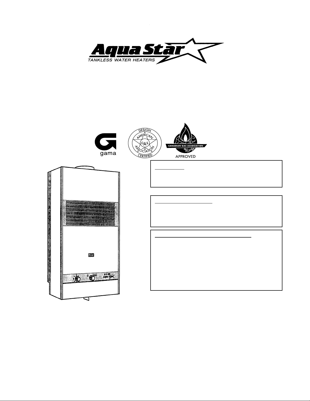
INSTALLATION AND OPERATING INSTRUCTIONS
FOR AUTOMATIC INSTANTANEOUS TYPE WATER HEATERS
FOR USE WITH NATURAL AND LIQUEFIED PETROLEUM GAS
MODEL 80 VP AND MODEL 80VPS
Suitable for water (potable) heating and space heating
WARNING: If the information in this manual is not
followed exactly, a fire or explosion may result
causing property damage, personal injury or death.
FOR YOUR SAFETY
Do not store or use gasoline or other flammable,
combustible or corrosive vapors and liquids in
the vicinty of this or any other appliance.
WHAT TO DO IF YOU SMELL GAS
• Do not try to light any appliance.
• Do not touch any electrical switch; do not use
any phone in your building.
• Immediately call your gas supplier from a
neighbor's phone. Follow the gas supplier's
instructions.
• If you cannot reach your gas supplier, call the
fire department.
- Installation and service must be performed
by a qualified installer , service agency or
the gas supplier .
Upon completion of the installation, these instructions should be handed to the user of the appliance for
future reference. *REPLACEMENT MANUAL MUST BE PURCHASED
FEA TURING: Variable Power - Modulating Gas V alve - Thermostatic Control with Temperature Dial Selector
Page 2

TABLE OF CONTENTS
Specifications ..............................................................................Page 3
Rules for Safe Operation.............................................................Page 4-5
General Overview of Aquastar ....................................................Page 6
Locating the Heater for Safe Proper Combustion........................Page 7
Installation ...................................................................................Page 8
Connecting Gas and Water Lines & Pressure Relief Valve .........Page 9-10
Vent Pipe Connection..................................................................Page 10
Safety Before Lighting.................................................................Page 11
Lighting Instructions ....................................................................Page 11
Setting Water Temperature..........................................................Page 12
Maintenance & Service ...............................................................Page 12-14
Trouble Shooting.........................................................................Page 14-18
Cleaning Pilot Assembly..............................................................Page 19
Calibration and Thermostat Test..................................................Page 20-21
Description of Operation and Parts Layout Diagrams .................Page 22-26
Gas Line Size, Vent Size & Height Guide Lines..........................Page 27
This well engineered, tankless gas water
heater has all the features a water heater
should have:
The instantaneous principle of heating water is
very simple. Cold water enters the heater when
a hot water faucet is opened. This flow of water
causes the gas valve to open. Gas flows to the
burners and is ignited by the pilot flame. The heat
exchanger then absorbs the heat generated by
the burners and transfers it to the cold water as it
travels through the heat exchanger. When the hot
water is turned off, the gas valve automatically
closes and the burners shut off. Your hot water
faucet is an ignition key for hot water . You now
have complete control over your hot water energy
use. [See pages 22-26 for detailed Description
of Operation and Parts Layout Diagrams].
FEATURES
• Automatic thermostatic control for steady
hot water temperature. Burner output is
proportional to water flow for maximum
energy efficiency .
• Automatic thermostatic control for steady
hot water temperature.
• Safety thermocouple at pilot and burner.
• Automatic Energy Cut-Off mechanism.
• Built-in gas shut-off valve.
• Stainless steel burners with stabilized blue
flame.
• Built-in corrosion resistant draft inducer.
• Long working life insured by heavy-duty
high quality materials.
• Compact space saver: mounts on wall
with four screws.
• Easy installation.
• 2.2 gpm (removable) flow restrictor to
ensure water flow will never exceed heater
capacity .
2
Page 3
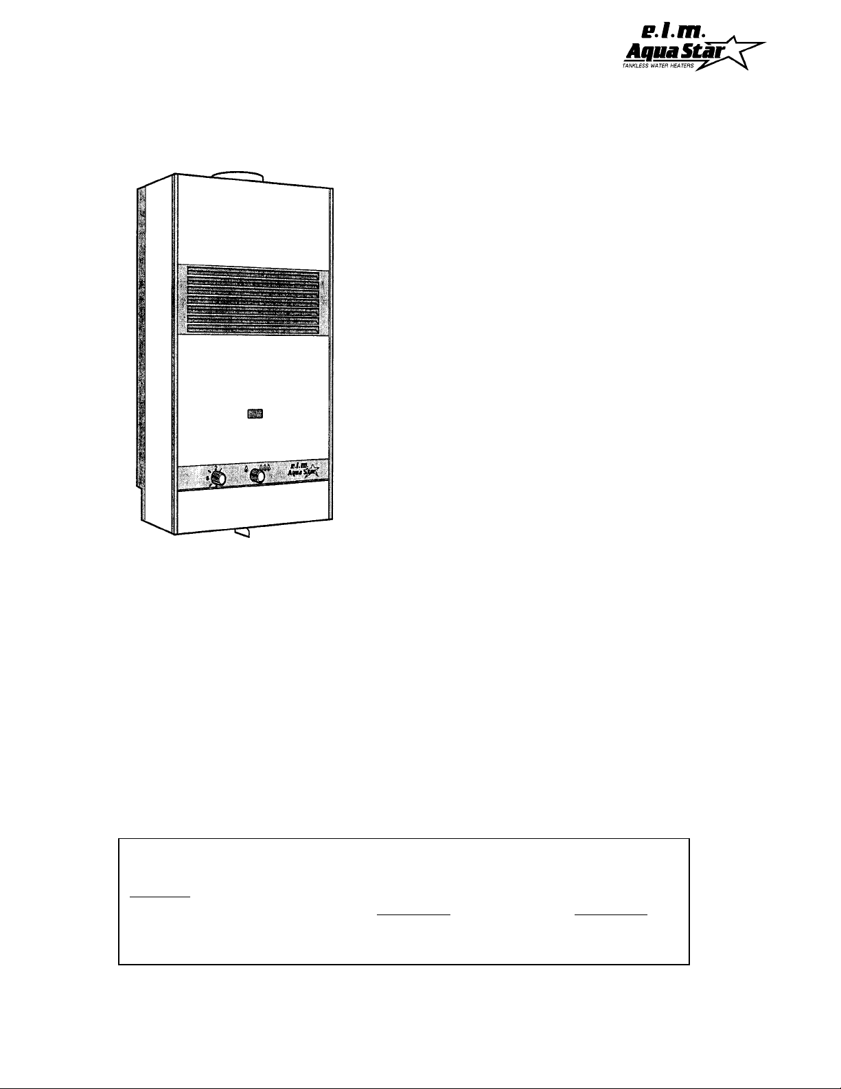
AquaStar 80 VP and 80 VP "S" Specifications:
Gas input..................................max: 77,500 Btu
Water Connection........................1/2" sweat fitting
H x W x D..........................................27" x 12" x 9"
Vent.......................................................................4"
Gas Connection...........................3/4" NPT thread
Min. Water Pressure....................................15 Psi
Max. Water Pressure................................150 Psi
Shipping Weight..............................................33 lb
Net Weight......................................................27 lb
GPM at 90ºF rise...........................................1.32*
GPM at 45ºF rise...........................................2.64*
Min. Water Flow ....................................3/4 gal/min
LP GAS Pressure inlet...............min.: 10"W.C.***
LP GAS Manifold pressure....................8.9" W.C.
Natural Gas Pressure inlet..........min.: 4.7"W.C.***
Natural Gas Manifold Pressure...............3.2"W.C.
min: 25,000 Btu
max.: 14"W.C.**
max.: 14"W.C.**
* Figured on a 55ºF cold inlet temperature
** Inlet gas pressure must not exceed this value
***For purposes of input adjustment
SETTING THE INLET GAS PRESSURE FOR HIGH ALTITUDES
The pressure regulator provided with the heater is set to deliver the proper gas pressure (as
indicated on the rating plate and in the manual) for altitude up to 2500 feet (758 meters) above sea
level. On appliances being installed above 2500 ft/ 758 m elevation, the inlet gas pressure should
be reset at installation to the value shown below for the altitude of the installation.
NOTE: The gas pressures specified below refer to pressures taken at the test pressure
nipple on the manual gas valve as shown in fig.3 page 9. These readings should be taken
while the heater is operating at full output --i.e. maximum water flow with the temperature
setting on #8.
MAXIMUM INLET GAS FLOW PRESSURE SETTING
AL TITUDE NATURAL GAS LIQUID PROPA NE
inches W.C. inches W.C.
0' - 2,500 FT / 758 M 3.90" 9.75"
2,500 ft - 4,000ft / 758m - 1212m 3.00" 7.35"
3
Page 4
CAUTION: RULES FOR SAFE OPERATION
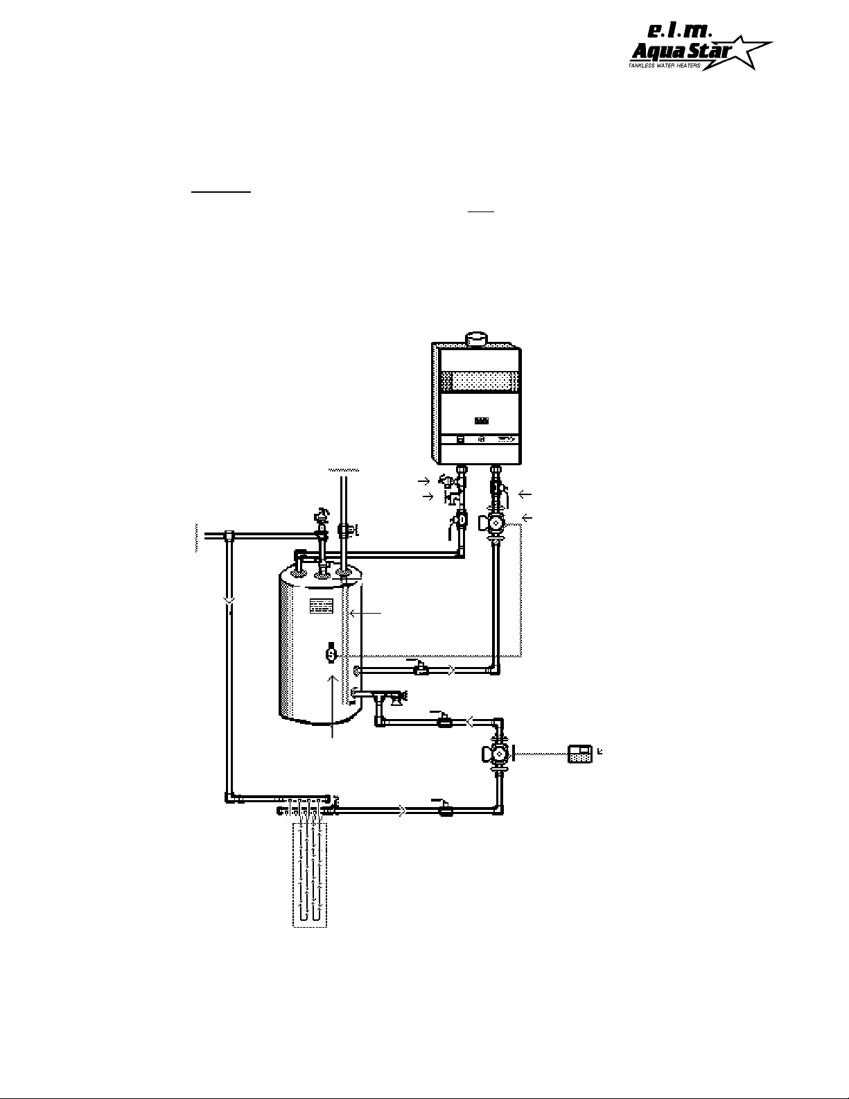
If you are using the AquaStar for combined space heating and potable water heating (
schematic diagram below),
all piping and other components connected to the system must
see
be suitable for potable water, (b) toxic chemicals such as those commonly used for boiler
treatment to prevent corrosion and freezing must not be introduced into the system, and
(c) if the space heating requires water temperatures higher than those required for domestic, potable water, a mixing valve or other similar device must be provided to reduce
scald hazard potential. DO NOT CONVERT AN EXISTING, CLOSED HOT WATER HEA TING
SYSTEM TO A COMBINATION SPACE AND POTABLE WATER HEATING SYSTEM USING
THE AQUASTAR OR ANY OTHER HEAT SOURCE.
Cold
Water
Hot
Water
Out
Pressure
In
Relief
V alve
Boiler Drain
Full Port
Ball V alve
Full Port
Ball V alve
Pump (Grundfos
UP26-99BF ,
T aco 001 1B
or equivalent)
Dip Tube
Secondary
Pump
Aquastat
Sensor
Radiant Floor,
Low T emperature
Fan Coil Units,
Baseboard Heaters,
Indirect Water Heater ,
Snow Melt, or
Root-zone Grid
Fig. 1 Schematic Diagram of Combination Potable Water and Space Heating System
Room
Thermostat
4
Page 5

RULES FOR SAFE OPERA TION
1. Y ou should follow these instructions when you
install your heater.
In the United States: The installation must conform with local codes or , in the absence of local
codes, the National Fuel Gas Code ANSI Z223.1/
NFPA 54.
In Canada: The installation should conform with
CGA B149.(1,2) INST ALLA TION CODES and/
or local installation codes.
2. Carefully plan where you install the heater. Correct combustion air supply and flue pipe installation are very important. If a gas appliance is
not installed correctly , fatal accidents can result
from lack of air , carbon monoxide poisoning or
fire.
3. The place where you install the heater must
have enough ventilation. The National Fire Codes
do not allow water heater installation in bathrooms, bedrooms or any occupied rooms normally kept closed. See the section on Pages 7-8
on Locating the Heater.
4. Y ou must vent your heater. See section on V ent
Pipe Connection, Page 10, paragraph 6 and
V enting Guide on page 27.
6. Keep water heater area clear and free from
combustibles and flammable liquids. Do not locate the heater over any material which might
burn, such as carpet.
7. Correct gas pressure is critical for the optimum
operation of this heater (see specifications on
page 3). Gas piping must be sized to provide
the required pressure at the maximum output of
the heater. Check with your local gas supplier,
and see gas line size requirements on page 27.
8. As a precaution, shut off your heater if you plan
to be away for several days.
9. Should overheating occur and the gas supply
fail to shut off, turn off the manual gas control
valve to the appliance.
10. See instructions on setting the water tempera-
ture, page 12.
11. Do not use this appliance if any part has been
under water. Immediately call a qualified service
technician to inspect the appliance and to replace
any part of the control system and any gas control which has been under water.
5. The appliance and its individual shutoff valve
must be disconnected from the gas supply piping system during any pressure testing of that
system at pressures in excess of 1/2 psig
(3.5kPa).
The appliance must be isolated from the gas
supply piping system by closing its individual
manual shutoff valve during any pressure testing
of the gas supply piping system at test pressures
equal to or less than 1/2 psig (3.5kPa). The
appliance and its gas connection must be leak
tested before placing the appliance in operation
5
Page 6
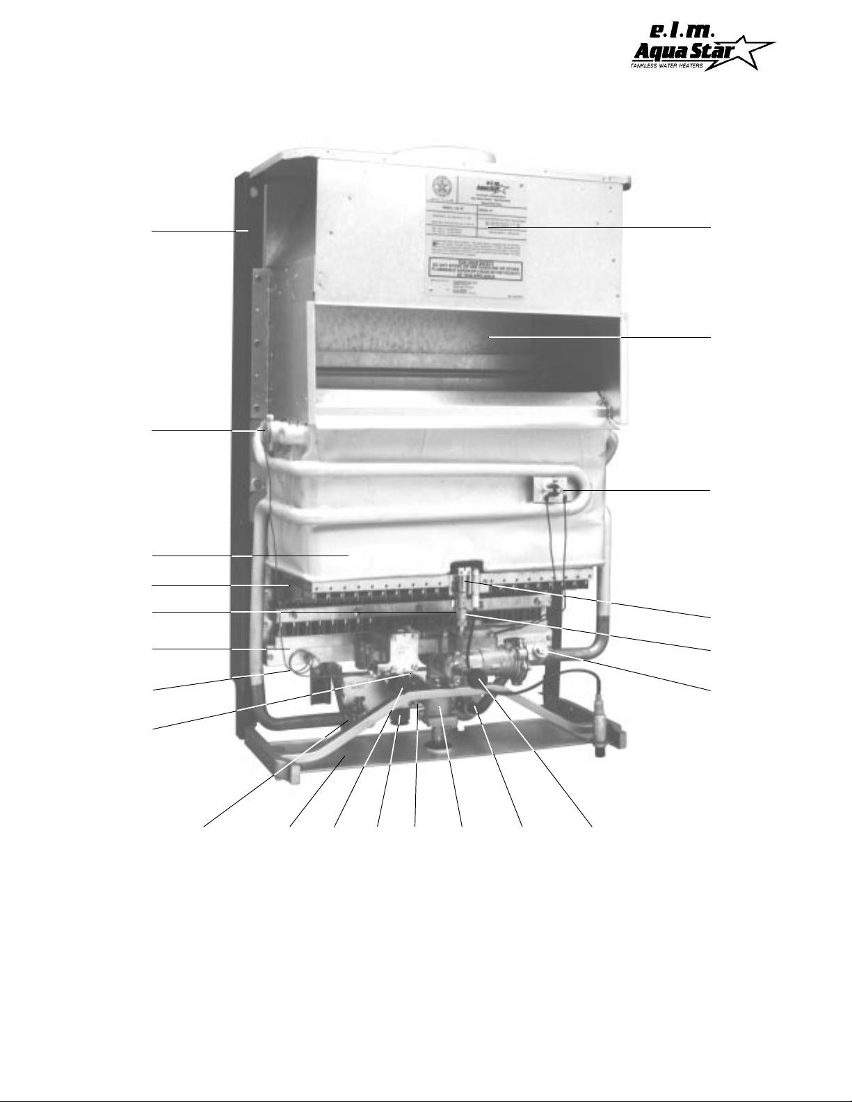
Fig. 2 Parts of AquaStar 80
D
A
B
C
E
X
W
V
T
F
G
J
I
A. hanging frame and back
support
B. thermostatic sensor
C. heat exchanger
D. thermocouple
E. burners
F. burner manifold
G. gas pressure testing nipple
H. temperature selector knob
Y
H
I. hot water outlet
J. thermostat adjustment screw
K. gas inlet
L. manual gas valve
M. cold water inlet screen
P. pilot starting button
R. water valve venturi piston
S. pilot filter
S
R
L
PMZK
T. pilot
V. overheat shut off sensor
W. draft hood
X. rating plate-serial #
& gas type, etc.
Y. incandescent particles tray
Z. gas pressure testing nipple
or gas valve
6
Page 7

LOCATING YOUR HEATER FOR SAFE PROPER COMBUSTION
Carefully select the location of your new heater. For your safety and for proper heater operation,
you must provide an abundant supply of combustion air and install a proper vent. The heater
may still operate even when improperly installed. However, an improper installation will be less
efficient and may damage the heater. Improper installation can even result in human sickness or
death due to oxygen deprivation and carbon monoxide poisoning. Follow the guidelines below:
1. Y ou must not install this appliance in bathrooms,
bedrooms, unvented closets or any occupied
rooms normally kept closed.
2. Simultaneous operation of appliances such as
exhaust fans, ventilation systems, clothes dryers,
fireplaces or wood stoves may create a vacuum
effect in your home. This can cause dangerous
combustion by-products to spill back into your
home rather than venting to the outside through
the flue.
3. A simple test for proper ventilation is to
inroduce smoke (as from a candle) near the louvers on the front of the heater. Have all appliances mentioned in the above paragraph operating at the same time. Have all doors and windows to the outside shut. If the heater does not
suck the smoke into the louvers while the heater
is operating, you need to supply additional combustion air to the heater and/or improve the vent
system.
4. Observe the following instructions concerning
additional combustion air .
Appliances located in unconfined spaces:
a) An unconfined space is one in which
the volume is greater than 50 cubic feet
per 1000 Btu per hour of the combined
rating of all appliances installed in the
space. That would be 6250 cubic feet
for the AquaStar 125 alone.
b) In unconfined spaces in buildings of
conventional frame, masonry , or metal
construction, infiltration is normally adequate to provide air for combustion, ventilation, and dilution of flue gasses.
Appliances located in confined spaces:
The confined space shall be provided
with two permanent openings, one commencing within 12 inches of the top and
one commencing within 12 inches of the
bottom of the enclosure. Each opening
shall have a minimum free area of one
square inch per:
-1,000 Btu/hr if all air is taken from inside
the building.
-2,000 Btu/hr if all air is taken from the
outside by horizontal ducts.
-4,000 Btu/hr if all air is taken from the
outside by direct openings or vertical
ducts.
Louvers, grills and screens have a blocking effect. If the effective free area is not
known, assume 20% to 25% for wood louvers and 60% to 75% for metal louvers.
Refer to the National Fuel Gas Code for
complete information. In buildings of tight
construction, all air should be taken from
outside.
5. Place your heater as close to a vent or chim-
ney as possible. Y our hot water lines should be
kept short to save energy. It is always best to
have hot water lines insulated.
6. Having a floor drain or sink nearby is handy in
case you need to drain water from your heater.
7. Place the heater in a location where water
leaks will do NO DAMAGE to adjacent areas or
lower floors. CONTROLLED ENERGY CORP
IS NOT RESPONSIBLE FOR WATER DAMAGE.
7
Page 8

8. For alcove installation, maintain the following
minimum clearances from all construction for servicing and proper operations:
Alcove Closet
A. Top 6 inches 12 inches
B. Front OPEN 6 inches
C. Back 0 inches 0 inches
D. Sides 1 inch 1 inch
(Left side 6" for service)
E. Floor 6 inches* 12 inches*
F. Flue 6 inches 6 inches
(single wall only)
*Do not install over floor covering which is combustible,
such as carpet.
Minimum clearance to combustible materials
should not be less than 6" for single wall flue pipe.
Note that this can be reduced if combustible
materials are protected as per table VI of the
National Fuel Gas Code or if Type B gas vent is
used. (Follow the minimum clearances for the
vent type. We recommend the use of T ype B gas
vent.
9. WARNING: THIS WATER HEATER DOES
NOT STORE ANY HOT W ATER. DO NOT INSTALL IN AN AREA WHERE IT COULD
FREEZE. This heater is neither designed for
nor approved for outside installation.
10. The heater must be level before you begin
the piping.
INST ALLA TION
Before installing the unit, be certain your heater
is for your type of gas - Propane or Natural Gas.
Identification labels for type of gas are found on
the shipping box, on the right side panel and on
the rating plate which is located in upper part of
draft hood seen by removing front panel (See
"X" Fig. 2, page 6). Also, each gas orifice is
stamped with a number (75 for LPG and 1 15 for
Natural Gas).
1. Hanging the heater on the wall
Place the paper pattern or template (supplied with
heater) on the wall where you plan to hang your
heater. Use the adhesive tape which is included
in the package to stick the pattern to the wall.
Keep in mind that the heater needs to have certain minimum clearances (See paragraph 7 on
this page), and that the heater must be level. Drill
four holes into the wall at the studs (16 inches on
center) as indicated on the template. Use a 1/8
inch drill if screws are to go directly into wood or
1/4 inch if plastic anchors are to be used.
WARNING: Be sure to remove the paper
template before hanging the heater on the
wall.
After the paper template is removed, insert the
mounting screws into the two upper holes. Leave
1/2 inch between the wall and the screw head, in
order to have enough space for your unit to slip
over. The bottom screws will secure the Water
and Gas Connecting Strip Assembly to the wall.
Next remove the front panel. T o do this, remove
the temperature selector knob (H) and the pilot
starting button by pulling them out. Unscrew the
screws under each front corner. Lift the panel up
and pull out. At this point, you can either screw
the two large screws to fasten the Water and Gas
Connecting Strip Assembly to the wall using the
pre-drilled holes and connect your pipes directly
to the water heater, or you can remove the heater
from the Water and Gas Connecting Strip Assembly in order to connect the piping, and then reconnect the heater later. If you decide to connect
the pipes directly , skip the next section and go to
#3, "Connecting the Gas Line."
2. T o Disconnect Heater From the Water and
Gas Connecting Strip Assembly (Optional)
Refer to figure 3 (following page). Unscrew each
brass union nut at the three points marked in figure 3. Be careful not to lose the washers. Remove your heater from the Water and Gas Connecting Strip. Now you can make your water and
gas connections as explained in the following
sections. When all connections have been made,
re-hang the heater on the upper screws and reconnect the brass union nuts making certain that
the washers are properly in place.
8
Page 9
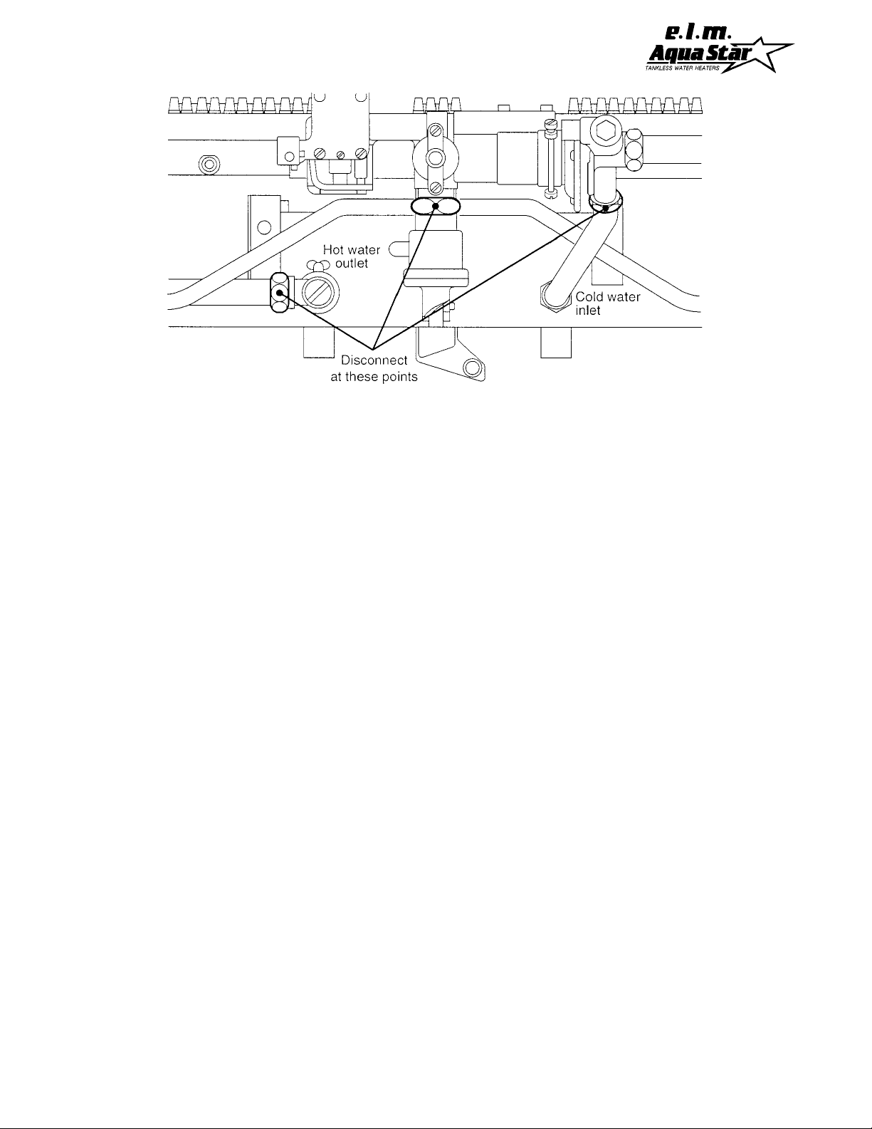
Fig. 3 T o Disconnect Heater From Wall Hanging Strip
3. Connecting the Gas Line
In the United States: The installation must conform with local codes or, in the absence of local
codes, the National Fuel Gas Code ANSI Z223.
1/NFP A 54.
In Canada: The installation should conform with
CGA B149 INSTALLATION CODES and/or local installation codes.
IMPORT ANT An appliance gas pressure regulator has been supplied with this unit. This regulator must be installed on the gas line within 6 feet
of the heater. National Fuel Gas Code requires
that a sediment trap be installed on gas appliances not so equipped. The 3/4" NPT gas inlet
elbow fitting supplied with the heater connects to
the manual gas shutoff valve with a washer gasket. No pipe dope or thread tape should be used
at this joint. The 3/4" NPT side of the fitting has a
hex shoulder to help you avoid twisting the elbow
and requires pipe dope or thread tape to make
its seal. The 3/4" size is the minimum for use
with Natural Gas and must not be reduced. Propane gas line size requirements are less than
those for Natural Gas. Provided the propane gas
line is less than 20 feet and serves only the
AquaStar, it can be reduced to 5/8". When
threading the gas pressure regulator to the gas
piping, the indicator arrow on the regulator must
be pointed in the direction of gas flow.
NOTE: The regulator supplied with the
heater is an appliance level regulator designed for low inlet pressure (less than 1/2
LB or 15"W.C.). DO NOT connect to an unregulated or high pressure propane line.
When your connections are made, check for gas
leaks at all joints (not just ones you made). Apply
some soapy water to all gas fittings and gas valve.
Soap bubbles are a sign of a leak.
NOTE: Do not apply soap solution to pilot filter
screen or pilot orifice area. If you have a leak,
shut off the gas. After verifying that required gaskets are in place, tighten appropriate fittings to
stop leak. Turn the gas on and check again with
a soapy solution. Never test for gas leaks using
a match or flame.
4. Connecting the water lines
Although water piping throughout your structure
may be other than copper , copper piping should
be used for at least three feet before and after
the heater (follow local codes if more stringent).
Keep water inlet pipe to at least 1/2 inch diameter to allow the full flow capacity. Remember
that piping and water pressure must allow sufficient flow to activate the heater when drawing hot
water from the top floor. If the hot and cold connections are reversed, the heater will not function.
9
Page 10

Sweat your cold water pipe to the AquaStar inlet
elbow fitting. NOTE: The inlet filter screen and
water flow restrictor can be damaged by heat
if the cold water inlet elbow is attached to
the AquaStar when it is sweated to the cold
water inlet pipe. The inlet and outlet elbow fit-
tings seal by means of a union connection with a
washer type gasket at the joint. Although these
fittings have 1/2" threads, NPT fittings should not
be substituted for these elbows and no pipe dope
or thread tape is to be used at the joints. Be certain there are no loose particles or dirt in the piping. Blow out or flush out the lines before connecting to the AquaStar.
5. Connecting the pressure relief valve
A temperature and pressure relief valve must be
installed on the hot water line, close to the heater.
No valve is to be placed between the relief valve
and the heater. Installation shall be made in such
a manner that the discharge from the temperature and pressure relief valve will be conducted
to a suitable place for disposal when relief occurs. No reducing coupling or other restriction
may be installed in the discharge line. The discharge line must be installed such that it allows
complete drainage of both the valve and the line.
The location of the relief valve must be readily
accessible for servicing or replacement. To accommodate the pressure relief valve, a suitable
fitting connected to an extension of a "T" fitting
can be sweated to the line. Make the T-fitting
extension long enough to ensure that the temperature probe does not interfere with the water flow.
The relief pressure of the valve must not exceed
150 psig. The relief temperature of the valve must
not exceed 210ºF and the discharge capacity
must be at least 125,000 Btu per hour.
6. Vent pipe connection. W ARNING: Do not
reduce the vent pipe size.
This appliance must be vented to the outside following all local ordinances and specifications for
installing a gas appliance vent or chimney . The
venting system must be constructed so as to
develop a positive flow adequate to remove flue
gasses to the outdoors under all operating conditions.
The appliance must be located as close as practicable to a chimney or vent. The vent pipe sections must be fastened with sheet metal screws.
Keep in mind the minimum clearance from the
top of your heater. Remember also that single
wall vent pipe connectors require a 6 inch clearance from combustibles. National Fuel Gas Code
specifies double wall - Type "B" - vent pipe be
used in cold climates and for gas vents running
through attics. We consider double wall vent pipe
preferable in all circumstances. The vent connector should have as much vertical rise as possible (minimum 12") before any horizontal run.
Any vent section greater than 45 degrees from
vertical is considered horizontal. Horizontal sections of vent connectors must slope upwards at
least 1/4 inch for every foot of its horizontal length.
Keep the horizontal section short and avoid too
many elbows.
Note: Although the AquaStar has the same venting requirements as other Category I gas appliances, certain features and specific use characteristics make it more important to have a venting system which exceeds minimum standards.
AquaStar thermostats modulate burner output.
Therefore, when operating at less than full output, the heater does not have its full heating capacity to warm the flue pipes to create a natural
draft. Most gas appliances have longer duty
cycles than are typical of instantaneous heaters.
For these it is considered sufficient if the appliance can overcome a downdraft within the first
five minutes of operation. An instantaneous "on
demand" heater like the AquaStar may have
frequent operating cycles of less than a minute.
If venting and air supply are inadequate to provide a positive draft as soon as the heater turns
on, the heater may not remain on long enough to
establish a positive draft. See venting guide on
page 27.
10
Page 11
FOR YOUR SAFETY READ BEFORE LIGHTING
WARNING: If you do not follow these instructions exactly, a fire or explosion
may result causing property damage, personal injury or loss of life.
A. This appliance has a pilot which must be
lighted by hand. When lighting the pilot,
follow these instructions exactly .
B. BEFORE LIGHTING smell all around the
appliance area for gas. Be sure to smell
next the floor because some gas is
heavier than air and will settle on the floor.
WHA T TO DO IF YOU SMELL GAS
• Do not try to light any appliance.
• Do not touch any electrical switch; do
not use any phone in your building.
• Immediately call your gas supplier from
a neighbor's phone. Follow the gas
suppliers's instructions.
LIGHTING INSTRUCTIONS
1. STOP! Read the safety information
above.
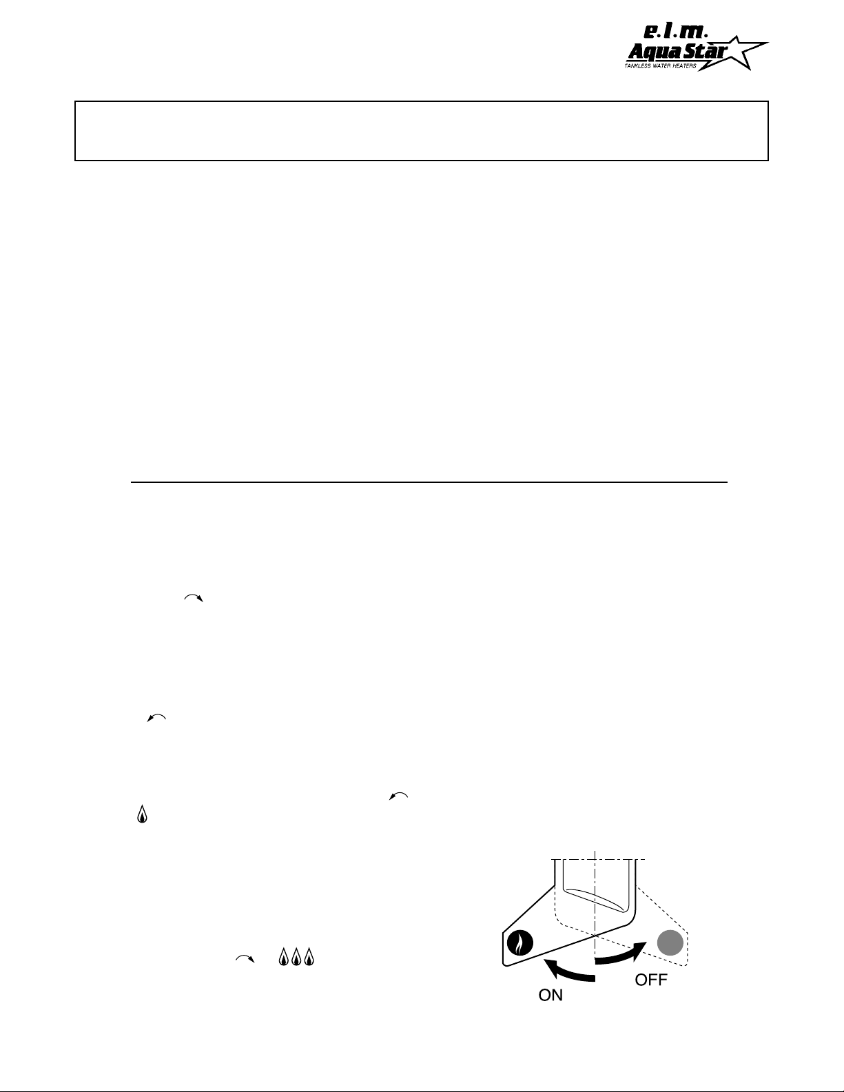
2. Push in gas control handle slightly and turn
clockwise to "RED DOT" position.
3. Wait five (5) minutes to clear out any gas.
If you smell gas, STOP! Follow "B" in the
safety information above. If you don't smell
gas, go to next step.
4. Turn handle on gas control counterclockwise to "RED FLAME" position.
5. Check that manual gas valve handle is on
"RED FLAME" position. Push in center
PILOT LIGHTING knob on the front of the
AquaStar and twist counterclockwise
to .Push knob all the way in and hold it
in. While holding knob in, light the pilot
with a match through pilot viewing open
ing in front of the heater. Check that pilot
• If you cannot reach your gas supplier,
call the fire department.
C. Use only your hand to push in or turn the
gas control knob. Never use tools. If the
knob will not push in or turn by hand, don't
try to repair it, call a qualified service tech
nician. Attempted forceful repair may re
sult in a fire or explosion.
D. Do not use this appliance if any part has
been under water. Immediately call a
qualified service technician to inspect the
appliance and to replace any part of the
control system and any gas control which
has been under water.
In the United States: The installation must conform with local codes or , in the absence of local
codes, the National Fuel Gas Code ANSI Z223.
1/NFP A 54. In Canada: The installation should
conform with CGA B149 INSTALLATION
CODES and/or local installation codes.
If knob does not pop out when released, stop
and immediately call your service technician or
gas supplier. If the pilot will not stay lighted after
several tries, turn the gas control handle off to
"RED DOT" position and call your service technician or gas supplier.
TO TURN OFF GAS TO APPLIANCE
Turn gas control shut off handle to the "RED DOT"
symbol. Do not force.
is lighted. Keep the center knob pressed
all the way in for at least 10 seconds after
pilot is lighted. Release push knob and
turn it clockwise to
If pilot goes out, wait 5 minutes before
relighting.
11
Page 12
SETTING THE W ATER TEMPERA TURE
The AquaStar 80 water heater contains a flow
restrictor set at 3 1/4 gpm. Its purpose is to assure that the hot water temperature will always
be within a comfortable range regardless of how
high one may turn on the hot water faucet or how
many faucets may be turned on. Y our AquaStar
model 80 also has an automatic thermostatic control with a manual temperature setting (Fig. 2 letter H p. 6). For energy efficient operation, we
recommend operating this heater at the lowest
temperature which you require in your application. This will provide a more consistent temperature over a wider range of flow . Lower temperature settings help prevent temperature fluctuations
that may occur when other water outlets are used
simultaneously or overall water pressure changes
or excessive cold water has to be added. In hard
water areas, reducing the water temperature
greatly reduces the potential for mineral scale
build-up in the heat exchanger .
What is the best temperature setting?
Because AquaStar water heaters can deliver
endless hot water at the exact temperature which
you have selected, there is no need to set it for
very hot water and then mix in cold. It just doesn't
make sense to overheat water then mix in a lot
of cold water to cool it off. Remember you cannot run out of hot water with an AquaStar, so set
the dial for the (exact) temperature that you need.
Note: 105ºF is the maximum recommended
for a hot bath. The temperature you select will
hold over a range of water flow rates. (See chart,
Fig. 6, page 18). Y ou may further vary the temperature by signficantly changing the flow rate,
particularly at the highest temperature settings.
Position "5" on the temperature dial is the preferred starting point for setting the temperature
control. This setting provides approximately
130ºF depending on the flow rate.
Positions "2" and "3" provide approximately
105ºF , adequate for a shower depending on flow
rate.
Positions "4" through "6" are intermediate settings between warm and very hot.
Position "8" allows for the hottest temperature of
about 150ºF up to about 1.8 gallons per minute.
WARNING: 150ºF can cause third degree
burns.
model "S" version heater. The model "S"
is a specifically modified AquaStar which will
not overheat if inlet water is already hot.
MAINTENANCE AND SERVICE
Approximately once a year, the AquaStar should
be checked, cleaned and serviced as necessary .
The following operations must be performed by
a qualified service person:
Vent System: Should be checked annually.
Clean and repair as needed.
Water V alve (Part #34343): The water valve on
this heater should be serviced periodically depending on hardness of water and conditions of
use or whenever signs of corrosion appear at the
gas and water valve joint. Servicing the water
valve consists of replacing the Push Rod Assembly (part #21 107), the Diaphragm (part# 32570),
and the Water V alve Spring Loaded Piston (part
#34542).
Drainage: Drain the heater if there is any danger of freezing. Shut off the water supply , open
all hot water faucets, and disconnect the lowest
AquaStar fittings and the connections to the water valve (Fig 2, (R), page 6). Loosen the 2 retaining screws at the connection to the gas valve
and rotate the water valve 360o to empty all the
water. The pressure-temperature relief valve operation should be checked. Perform a manual
operation of this valve at least once a year ensuring that a drain is nearby to receive any discharge (see section 5, page 10). Take precautions to avoid contact with hot water coming out
of discharge opening and to prevent water damage. Do not plug the relief valve. If the relief
12
Page 13
valve discharges by itself, a problem exists and
service is required. This could be due to a defective relief valve or to overheating.
Pilot Flame: The pilot flame should burn with
a clean sharp blue flame and should resemble
Fig.4 below. If the flame is yellow, or if the
central button Fig. 2 (P) has to remain depressed for a long time in order to keep the pilot
lighted, the pilot may need to be cleaned or the
orifice replaced.
- to thermocouple
to burners -
Fig. 4 Characteristic Pilot Flame
To clean the pilot:Turn off the gas at the unit
Fig. 2 (L). Remove the front panel (unscrew
screws at bottom of corners of front panel, pull
out and lift panel off). Disconnect the Pilot Tube
Fig. 2 (S) at its base and blow gently through it
(
see diagram of Pilot Assembly, page 19).
Be
careful not to lose the pilot orifice and
washers. Remove and clean pilot filter by
peeling off the outer layer . Do not use any wire
or sharp object to clean orifices. Natural gas
orifices are large enough that you can usually
clean them by blowing through them. LP orifices
are too small to clean and should be replaced.
Do not enlarge the orifice.
Wash the stainless steel burners if they are dirty .
Burners can be detached from the heater by removing the pilot tube and the thermocouple assembly and disconnecting the Energy-Cut-Off.
(Do not lose the retaining clip) The burners
are secured to the main frame by two screws on
either side. Do not remove the five screws across
the front of the burner assembly . Also examine
heat exchanger fins for dirt. Brush and vacuum if
dirty . Burnt edges at the bottom of the heat exchanger shroud are a sign of inadequate air supply , poor venting or some other combustion problem. The cause of this situation must be corrected:
contact your installer , service agency or the gas
supplier.
WARNING: Accumulation of dust and lint on
the heat exchanger fins will reduce air flow
and could cause corrosion of the copper
heat exchanger. Keep the appliance area clean
and free from combustible materials, gasoline and
other flammable liquids and vapors. Do not obstruct the flow of combustion air and ventilation
air. If installed near a dryer , make sure the dryer
is properly vented, and that the AquaStar vents
properly when the dryer is operating.
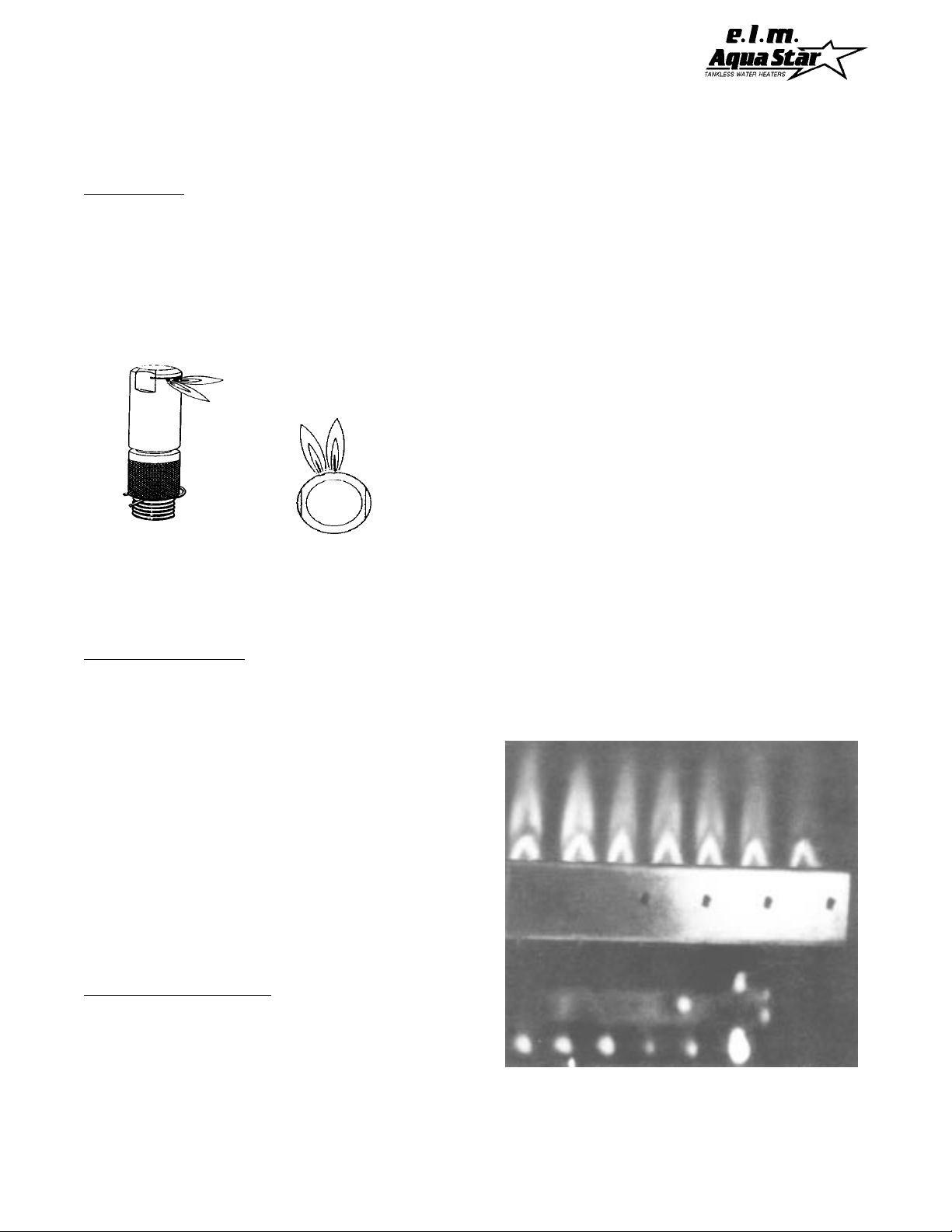
Main Burner Flames: The main burner flames
should be blue, with a more intense blue cone in
the center core.
column.
Y ellow flames could be a sign of wrong
Compare with Fig 5 in opposite
size gas orifices or dirty burners. If some burners have yellow flames while others have good
flames, it is likely that dust, lint or spider webs
have partially clogged the burner venturi.
Fig 5. Characteristic Burner Flame Pattern
13
Page 14

Mineral Scale Buildup:AquaStars, when operated at high temperatures or in hard water areas,
may need periodic descaling. To check the inside of the heat exchanger for scaling, remove the
heat exchanger by first removing the thermostat sensing element (B), page 6. If you note mineral
buildup, flush with a descaling solution. Consult your dealer or call CEC for instructions.
TROUBLE SHOOTING
Letter references, e.g. "L" in this section refer to
Fig. 2 on page 6.
Introduction: The AquaStar burners are ignited
by a water flow valve. Numerous water related
problems can cause this water valve to malfunction such as:
1. insufficient water flow volume to activate the
burners at their minimum flow requirement
2. dirt in the water flow valve causing the valve to
malfunction
3. sediment buildup in faucet aerators or shower
heads
4. uneven pressures between cold and hot (with
single lever faucets)
5. plumbing cross-overs
These water related problems can cause the
heater to deliver less than its full output, or to shut
down completely .
SPECIFIC PROBLEMS AND ANSWERS
Note: Problems are stated in upper case, bold
face. Most common causes for the problems follow in order of likelihood of occurence. For most
of the suggested solutions, it will be necessary to
take the front cover of the heater off. To do this,
pull the knobs off and remove the screws at front
bottom corners, then lift and pull the front panel
off. It is also advisable to remove the bottom tray:
pull off the plastic handle of the manual gas valve
and loosen the side panel bottom screws and then
pull the tray down.
PILOT WILL NOT LIGHT
1. No gas to the AquaStar
A. Gas cock on gas line may not be open.
B. AquaStar manual shut off valve at base of
heater is not open. Turn handle to red flame symbol.
2. In-line AquaStar gas regulator jammed
(usually with LP gas)
Replace or unjam the regulator. Note: The regulator furnished with the heater is designed for low
gas pressure. Excessive pressure will lock it up.
This problem usually happens if the gas pressure
between the gas tank and the water heater has
not been reduced. See page 3 of your manual
for specified gas pressures.
T o unjam a regulator , remove the nickel size screw
plug on the front. Inside you will see another large
screw. Draw a line down the threads to mark the
location of the screw. Remove the screw and push
on the bottom of the hole with the eraser side of a
pencil or similar object. This will release the diaphragm. Reinsert the screw and screw it down
to the end of the mark you made.
3. Pilot orifice cloggged and/or air screen
dirty , or pilot filter is dirty .
Clean the pilot orifice and/or pilot filter screen.
Disconnect the pilot tube (T) by unscrewing it. Be
careful not to misplace the small washers. The
diagram on page 19 shows how the parts of the
pilot assembly fit together.
Natural gas orifices are large enough that you can
usually clean them by blowing through them. The
LP orifice is so small that it is best to replace it.
Never try to enlarge the hole, or use a sharp
hard object for cleaning.
The pilot gas filter is made from a layered material. If it becomes too dirty , a portion of the filter
can be separated and peeled off. The clean portion should be loosely reinserted into the pilot
burner brass filter chamber. Be careful when reinstalling the pilot burner to aim the burner so that
the smaller right hand pilot flame touches the thermocouple tip.
14
Page 15

4. Pilot orifice may not be correct for your
type of gas.
Pilot orifice is stamped: #18 for LP and #35 for
NG.
5. Air in the Gas Line
Note: Normally this is a problem only at the time
of installation if the pipes have been worked on,
a propane tank has been allowed to empty, or
the heater has been shut down for a long time.
Bleed all the air trapped in the gas line. Because
of the very small pilot orifice (especially on LP
gas models), bleeding out all the air could take
several minutes. Hold the pilot push button
pushed in until all the air has escaped, and the
gas has arrived.
PILOT LIGHTS BUT FLAME GOES OUT
WHEN BUTTON IS RELEASED
1. Pilot push button was not pushed in far
enough or was not held in long enough
Push pilot button in, turn it to the left, then push it
in all the way. Hold it pushed in for at least 20
seconds to give time for the pilot flame to properly heat the tip of the thermocouple before releasing it.
See Lighting Instructions, Page 1 1.
2. Pilot flame improperly aimed or is too weak
so it is not properly heating the tip of the thermocouple
The pilot flame has two flames, one aimed at the
thermocouple and the other aimed at an angle
towards the burners (
Fig. 4, page 13).
see pilot flame diagram,
It is extremely important that
the flame directed on the thermocouple head be
aimed right at it, and that the pilot flame be a sharp
blue flame. If the pilot assembly has been taken
apart for cleaning, the pilot flame may no longer
be properly aimed.
3. Poor circuit connections at the ECO
(Energy Cut-Off)
Oxidation or looseness of the ECO screw connections can result in millivolt current loss through
the thermocouple safety circuit. Clean terminals
with very fine sand paper or an eraser and retighten terminal screws. (See letter V in Fig 2,
page 6).
4. Faulty Energy Cut Off (ECO)- Part 34209
If cleaning and retightening the screws on the thermocouple wires attached to the ECO did not fix
the problem, test the ECO by disconnecting a
wire from one side of it and reconnecting it to the
other side so both wires are making good contact. Relight the pilot. If the pilot flame now remains on, replace the ECO. If the flame still goes
out when the button is released, the ECO is not
defective. Go to the next step (#5 below).
5. Poor thermocouple connection at the electromagnet (part #20883)
Note: The electromagnet is located directly be-
hind the pilot push button assembly at the rear of
the gas control. Tighten the thermocouple connection to the electromagnet. The connection is
a large brass collar and a nut at the back of the
gas valve directly opposite the pilot push button
assembly. The thermocouple end is a 12 mm
(15/32") nut which screws into a 16 mm (5/8")
hex fitting on a brass collar. This large brass collar must be snug before you tighten the smaller
nut in order to avoid twisting and damaging the
thin copper thermocouple tube. Tighten the thermocouple nut snug but not too tight.
6. Faulty thermocouple or electromagnet
(parts #20887 and 20883).
Unless these parts are at least 8-10 years old,
it is very unlikely that they are faulty . Before
testing, reconfirm that #2 is absolutely correct, and all connections are clean and tight.
T o test the thermocouple, disconnect the thermocouple from the electromagnet and disconnect
the thermocouple wires from the ECO.
15
Page 16

Attach a multimeter lead on the thermocouple
copper tubing below the head, and attach the other
meter lead on the ends of both the wires. Light
the pilot and take a reading on the meter. If it
reads less than 24 mv , replace the thermocouple.
If the reading is 24 mv or over, the thermocouple
is good.
T o test the electromagnet, reconnect the thermocouple and take another reading. The reading
should drop to about 14 mv. If it does not, replace the electromagnet.
MAIN BURNERS DO NOT IGNITE WHEN
HOT WATER IS TURNED ON
a bad washer at a single lever faucet, incorrect
piping or an automatic mixing valve in the line
which permits hot and cold water to mix in the
plumbing. The crossover will create a back pressure in the system preventing the pressure drop
in the AquaStar - i.e. cold water is entering the
water valve from both sides and the burners will
not come on. T o confirm there is no crossover in
the plumbing, shut off the cold water supply to the
AquaStar. Open your hot water taps. There
should not be any water flowing. If there is water
flowing, there is a crossover in the plumbing. This
is a plumbing problem, not an AquaStar problem. Please contact your plumber.
1. Pilot is not on.
Light the pilot. See lighting instructions.
2. Pilot lighting push button not turned to
proper position
When the pilot flame is on , be sure that the push
button is released fully and is turned to the right
on the burner position (3 flames symbol).
3. Cold incoming water connection made to
wrong side of heater
Make sure cold water inlet connection is on the
right side of heater when you are facing the heater.
4. Water flow rate at hot water tap is too low .
Note: The AquaStar model 80 requires 3/4 gal-
lons per minute flow to activate the burners. This
is a flow which fills a quart jar in 20 seconds.
5. Cold water inlet screen on heater is dirty .
Remove this screen (M in Figure 2, page 6) and
clean it.
6. Crossover in household plumbing
The AquaStar burner activates when there is sufficient water pressure drop in the AquaStar water valve assembly when a hot water faucet is
opened. If there is a plumbing crossover, the
necessary pressure drop in the AquaStar will not
occur. A plumbing crossover can be caused by
7. Water valve parts may be dirty or components damaged.
Note: If #4 is OK, skip this.
Water valve and component parts must be totally
free of dirt. In hard water areas, mineral deposits can eventually (3-5 years) corrode water valve
parts to a point where they will need replacing.
Note: there is a small bleed hole under the gas
valve at the seam where it is connected to the
water valve assembly . Any sign of corrosion at
this location is a sign that the water valve assembly components need to be replaced immediately.
Water valve for Model 125 (34343)
consists of parts #21107, 32570 and 34542.
Contact service person to service the water valve.
PILOT LIGHTS BUT GOES OUT DURING OR
IMMEDIATELY AFTER HOT WATER USE
1. Thermostat calibration is incorrect
The thermostat is not maintaining the proper
burner output for the water flow and the heat exchanger is overheating. When this happens, the
ECO safety trips and shuts off the main gas supply . After the heat exchanger cools, the ECO resets and the pilot can be relighted. In order to
check the calibration, see page 20. If the thermostat cannot be calibrated properly , it is defective and must be replaced (see page 21).
16
Page 17

2. Gas pressure too low
Very low gas pressure may be caused by low
delivered gas pressure, by a jammed gas regulator or by undersized gas lines. If the gas lines
are undersized, there may still be the specified
static gas line pressure. However, when the water valve opens, the pressure will drop sharply,
causing the pilot flame to go out. Have a gas
service person confirm the gas pressure both
statically and at maximum Btu input. Specifications for your heater are on page 3.
3. Burners are not shutting down immediately when hot water is turned off
If burners don't shut off
immediately
when hot
water is turned off, the heater will overheat and
the ECO will shut off the gas. Replace all three
parts in the water valve assembly (parts #21 107,
34542, 32570. (See Letter R, Fig 2, page 6).
2. Water flow through the heater is higher
than the capacity of the AquaStar to heat it
If the AquaStar flow restrictor has been removed,
the flow through the heater might be higher than
its capacity to heat it. Reduce the flow to a range
within which the heater can maintain temperature.
See flow chart on Page 18. AquaStar water heaters have a (removable) flow restrictor to assure
that the maximum volume flowing through the
heater remains in the range that the heater can
heat to a suitable temperature, regardless of how
many faucets are being used. This is to ensure
that the flow is never higher than what the heater
can heat to a suitable temperature. The AquaStar
model 80 flow restrictor is set for a maximum of
2.2 gallons per minute. Note: In private well in-
stallations, the high and low cycling control of your
water pump may be set too low or the pressure
tank may be water logged.
WATER IS TOO HOT
1. T emperature setting is too high
Unlike storage tank heaters which need to be set
at a higher temperature than is needed in order
to stretch the volume of hot water by mixing in
cold water, an AquaStar can be set for the exact
temperature needed and give endless hot water
without need for mixing in cold water. We recommend setting the temperature selector dial on
#4 or #5. For more information, see section on
Setting Water Temperature, Page 12.
2. Inlet water temperature is too high (as with
preheated water)
Note: Only the Model "S" AquaStar should be
used if the inlet water is preheated.
3. Thermostat is not functioning properly
(See #1 under PILOT LIGHT GOES OUT DURING OR AFTER HOT WA TER USE)
WATER IS NOT HOT ENOUGH
3. BTU input is too low due to insufficient gas
pressure
It is extremely important for a tankless water
heater to have the right size gas line to obtain the correct gas pressure.
See specifications for correct gas pressures on
page 3. Unlike storage tank water heaters, the
burners of a tankless water heater must be very
powerful to heat water instantaneously since they
do this only at the time hot water is actually being
used. It is
imperative
that the gas pressure requirement be met exactly . Insufficient gas pressure will directly affect the water temperature.
Static gas pressure in the line can be measured
at the pressure test nipple located on the
AquaStar manual shut-off valve (Letter L, Fig 2,
Page 6). Manifold pressure may be tested at the
manifold presure test nipple (Letter G).
4. BTU input is too low due to insufficient gas
supply
Make sure your main gas line is fully opened. If
using LP gas, minimum size of the propane tank
should be 100 pounds for best results.
1. T emperature dial is set too low
Change the setting.
17
Page 18
5. Cold water is mixing with the hot water
between the AquaStar and the outlet
Compare water temperature at outlet of AquaStar
and at the tap. Check for automatic mixing valve
plumbing crossover (see #6 - MAIN BURNERS
DO NOT IGNITE WHEN HOT WA TER IS ON).
6. Parts in water flow valve (#34343) are
corroded
The gas valve will not open fully if water valve
parts are corroded. Replace all three parts in
water valve (#32570, #21 107, #34542).
HOT WATER TEMPERA TURE FLUCTUATES
1. T emperature setting is too high
Setting the temperature too high will make it necessary to add a great deal of cold water to make
the temperature safe and comfortable for contact
with the skin. Adding cold to the hot water flow at
the tap reduces the flow of water through the
AquaStar causing the thermostat to reduce the
Btu input or the water valve to shut off if the flow
through the AquaStar falls below 3/4 gallon/
minute. We recommend setting the temperature
selector dial on #4 or #5. See section on Setting
Water Temperature, Page 12.
2. Unbalanced pressure in water lines
The added restriction caused by theAquaStar in
the hot water system can result in uneven pressures between the cold and the hot. In such cases
when mixing cold water at the tap, the lower hot
water pressure may be overpowered by a much
higher cold water presure, which may cause the
AquaStar burners to shut down. Make sure faucet aerators or shower heads are free of minerals. Check that the flow restrictor and filter of the
AquaStar are clean
3. Cold water is mixing with the hot water
between the AquaStar and the outlet
Compare water temperature at outlet of the
AquaStar with the temperature at the tap. If different, check for automatic mixing valve or plumbing crossover (see #6, MAIN BURNERS WILL
NOT IGNITE) Where automatic "anti-scald"
valves are required by code, lower the temperature setting on the AquaStar as much as possible
and balance the pressure betwen cold and hot
water after the AquaStar.
4. Inlet water pressure is erratic due to inadequate supply water pressure or saturated
pressure tank on well system
Check the inlet water pressure and correct if necessary .
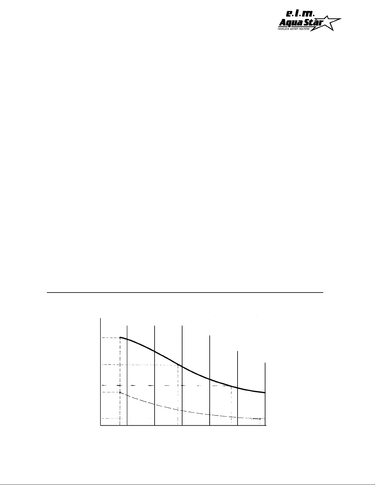
Fig. 6 Temperature/Flow Chart AquaStar 80
F°
155
150
145
140
135
130
125
120
115
110
105
100
HOT WATER TEMPERATURE
95
90
85
FLOWS IN GALLONS PER MINUTE -based on ground water temperature of 55ºF
*Range described above will be lower if inlet temperature is below 55ºF
1.0
1.5
2.0
2.5
18
T emperature chart of hot water
at different flow rates with
selector on position 8 ______
and position 2 _ _ _ _ _ _ _ _
3.0 3.5
Page 19
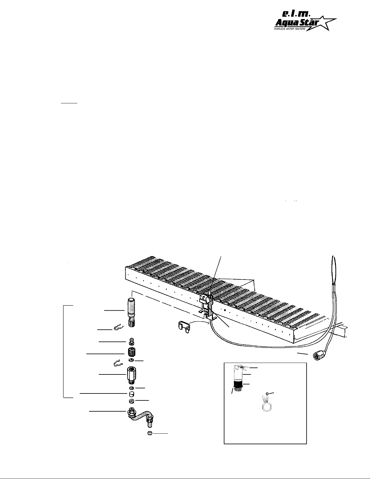
CLEANING THE PILOT ASSEMBLY
AquaStar models 80/125/170
A. Removing Pilot
1.Hold Gas Pilot Filter Housing in place with one
wrench.
2. Unscrew Pilot Tube nut with second wrench.
3.Save the little white Gasket for reassembly.
4. Pivot the tube to the left (loosen base fitting if needed).
5. Remove upper “hairpin” retaining clip.
6. Pull Pilot Assembly downward out of bracket.
B. Cleaning the Pilot
1. Separate the chrome Pilot Burner from the brass Gas
Pilot Filter Housing. Save the white Gasket for
reassembly.
2. Examine the Filter material for dirt. Blowing from the
top gets the filter material out of the brass housing.
Since the material is layered; dirty layers can be
removed. The remaining portion of the filter can be
loosely reinserted into the housing. Do not pack the
material into the housing as this can obstruct gas flow
to the pilot.
3. Check that the Air-Pilot Screen is clean and
unobstructed.
4. The pilot injector (orifice) must not be enlarged. The
natural gas orifice is large enough that you can
visually inspect and clean it. The LP orifice, however,
is so small that it is difficult to inspect or clean. We
recommend that you change the LP orifice if you
suspect that it might be partially obstructed. If you do
not have a replacement orifice, you may blow through
it or use a non-residue aerosol cleaning agent (like
that used for electronics) can be sprayed through
the orifice.
5. Clean any combustion residue from the Pilot Burner
tip. Make certain that both holes and the slit are clean.
C. Reinstalling Pilot Burner to Main Burner Bracket
1. Insert injector into base of Pilot Burner. Reattach
Filter Housing to base of Pilot Burner, making sure
to have the Gasket in between.
Be certain that the brass Gas Pilot Filter Housing is
snug to the Pilot Burner — use two wrenches to
tighten.
2. Pilot holes face in towards Main Burners. Slide Pilot
Burner ALL the way up into the bracket.
a) Insert Hairpin Retaining Clip to hold Pilot Burner in
bracket. Pivot the Pilot Tube back into position below
Filter Housing.
b) Insert the other Gasket between tube and Filter
Housing.
c) Use two wrenches to tighten Pilot Tube to Filter
Housing.
1) One wrench should hold Pilot Burner in right most
position, making sure right side flame is aimed
precisely on tip of Thermocouple.
2) Use second wrench to tighten Pilot Tube nut — DO
NOT OVER-TIGHTEN
Thermocouple
Pilot
Assembly
Pilot Burner
Hairpin
Retaining Clip
Pilot Injector
Screen
Pilot
Filter Housing
Filter
Pilot Tube
Gasket
Screen
Gasket
Thermocouple
Retaining Clip
Compression Ring
Main
Burners
Pilot Burner
Retaining Bracket
T o Electromagnet
Pilot Flames
Pilot Burner
Air Screen
Thermocouple
Screen
Retaining
Clip
View of Pilot Flame
as seen from
above
NOTE: Pilot flame must be
sharp blue, not soft and yellow
T o E.C.O.
19
Page 20
CALIBRATION AND THERMOSTAT TEST
SYMPTOMS OF A DEFECTIVE OR IMPROPERLY CALIBRATED THERMOSTAT:
The hot water is too hot. Usually this results in the heater shutting down on overheat
safety . The pilot frequently goes out and needs to be relighted.
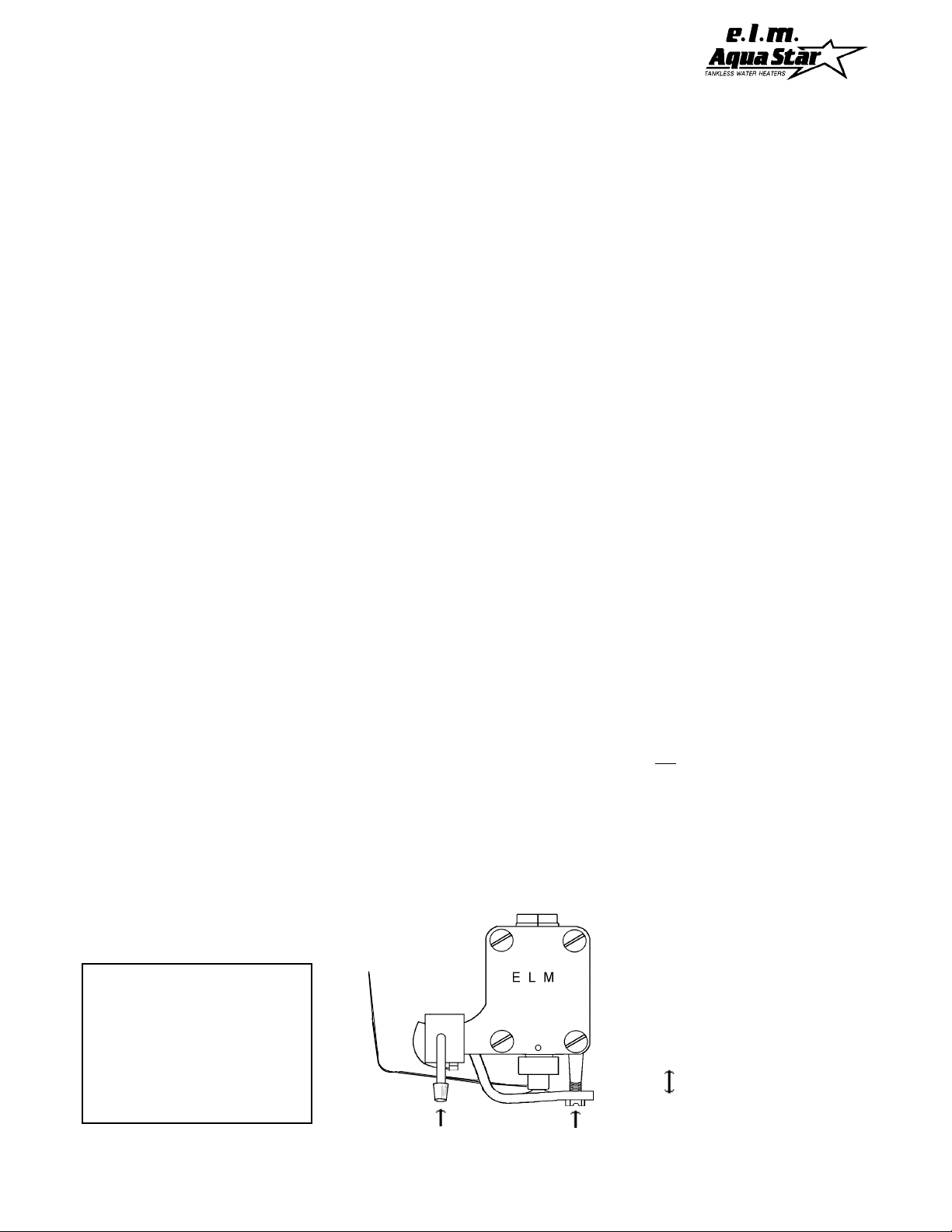
PROCEDURE TO CALIBRATE THERMOSTAT
(See diagram for correct location of screw to recalibrate)
1.Turn calibration screw in clockwise all the way , compressing the spring.
2.Back out screw 1 1/2 full turns. When set at the factory , the space from top to
bottom portion of the spring should be approximately 5/32" or 4mm.
NOTE: Turning the screw in (up) reduces the burner flames. Unscrewing it increases the
flames. If a thermostat is in good condition, and the calibration screw is properly
adjusted, the water temperature should be 145° (± 5) when temperature dial setting is
set at #8 and water is flowing at the minimum burner activating flow of
3/4 of a gallon a minute (Model 125/80) or 1.1 gpm (Model 170).
NOTE: Sometimes as a thermostat gets old (5 yrs or so), the space on the screw
adjustment may be too loose. In that case, turn the screw in another half or full turn more
if need be. It is important that you do not back this screw out so far that the burner
flames do not modulate and burners are always on full. Without modulation, the heater
will overheat and shut down.
TEST PROCEDURE TO CONFIRM THERMOSTAT IS WORKING PROPERLY
1. Turn AquaStar temperature setting to #8. This is all the way to the right, clockwise.
2. Turn on a hot water tap at the flow which will turn the AquaStar burners on. If the heater is working
correctly , this minimum activation flow will be 3/4 of a gallon a minute, for Model 125/80 and 1.1 for
Model 170. This is a flow that can fill up a quart jar in 20 sec. for the Model 125/80 and 15 sec. for the
Model 170. If the necessary flow to activate burners needs to be higher than the required minimum, see
water valve trouble shooting in your manual. The burners will come on at maximum fire and, within a
minute or so the burner flames will stabilize to a lower flame. Water temperature should be around
145°± 5. (This is scalding and too hot to put your hand under.) You should not be able to hold on to the
hot water pipe on the left side of the AquaStar.
3. Next turn the temperature dial all the way to the left to the lowest setting #2. Burner flames will become
quite small and should remain small. Water temperature, after a minute or so, should stabilize at about
105°± 5. Holding the hot water pipe should be comfortable.
4. Leaving temperature setting at #2, now , increase water flow on higher. Y ou should see the burner
flames increase in size, and then decrease when you reduce the water flow.
5. Note: If all of the above performs according to this description, the thermostat is working correctly .
Thermostat
Tubing to
Heat Exchanger
Note: Unless setting #8 (145°
± 5, this is scalding hot water)
is needed for some rare occasion we highly recommend running the heater on setting 4 or
5. This will also avoid the need
to mix a lot of cold water.
T emperature Dial
Thermostat
Piston
Assembly
Spring
Calibration Screw
Correct height
of spring - 5/32"
or 4mm
20
Page 21
PROCEDURE FOR REPLACING A THERMOSTAT
TO REMOVE THERMOSTAT:
A. Your replacement thermostat
comes as part of a kit. The kit
includes additional replacement
components to ensure a successful
installation. When removing the old
thermostat be certain to remove all
its components ("O" Ring, and Steel
Wedge) prior to installing the
replacement thermostat.
1. Shut off gas to the heater by
turning the handle on the main gas
valve.
2. Shut off the water supply to the
heater and open a faucet on the
lowest floor to drain the line and
relieve the pressure.
3. Remove the front panel, the left
panel, and the bottom tray.
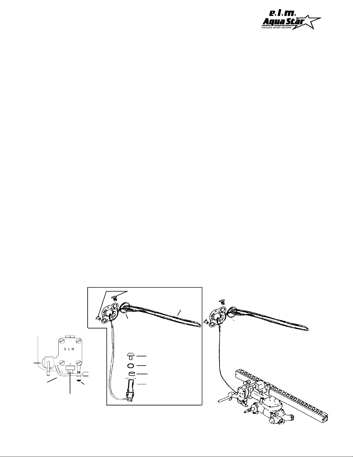
4. Remove the L-Shaped Lever,
spring and screw (see fig.A). Screw
is covered with a grey cap on newer
models. Back out the screw all the
way, being careful not to lose the
spring, and then remove the L-lever.
(Set these three parts aside as a unit,
ready to reinstall).
5. Pull down on the thermostat
piston assembly to remove it from
the gas valve.
NOTE: There is a Steel Wedge and
an "O" Ring which should come out
with the piston assembly. If they do
not, reach up with tweezers and/or a
magnet for the Steel Wedge and
remove them. Be especially careful
not to push the Steel Wedge into the
valve housing.
6. Remove the two screws at the
other end of the thermostat (located
on the upper left side of the heat
exchanger) and slide the capillary
sensor out of the heat exchanger.
Note: You should have a basin ready
to collect the water that will then be
released from the heat exchanger.
TO INSTALL NEW
THERMOSTAT:
B. When working with the
thermostat, be careful not to damage
it: The copper capillary tube is
hollow and can be damaged if
crimped or bent too sharply.
Retaining screw
1. Insert the capillary sensor into the
heat exchanger. Be sure that the rubber gasket seats properly and then
retighten the two screws.
2. Slide the new Brass Collar over the
piston.
3. Slide the "O" Ring over the piston
so that it seats above the Brass
Collar.
4. Place the Steel Wedge into the
piston cup. Position it so it is oriented with a flat side facing you. A
dab of grease or silicone will help it
stay in place.
5. Slide the assembly into the valve
housing, ensuring that the Steel
Wedge does not shift to an angled
position.
6. Reinstall the L-Shaped Lever,
spring and screw. Be sure the left
side of the L-lever is positioned over
the cam. Tighten the screw in all the
way so the spring is compressed.
Now calibrate the thermostat.
7. To calibrate the thermostat properly , continue with the calibration and
thermostat test on the following page.
fig.A
Thermostat
Tubing to
Heat Exchanger
Cam
L-Shaped Lever
Thermostat
Piston
Assembly
Spring
Screw
Grey cap
Rubber Gasket
Steel Wedge
"O" Ring
Brass Collar
Piston Cup
Thermostat assembly
Capillary Sensor
Into Left Side of
Heat Exchanger
Complete Gas Block Assembly
21
Page 22

DESCRIPTION OF OPERATION OF AQUASTAR 80/125 MODELS
WATER PATH
Cold water entering the Cold Water Inlet passes through
a nylon mesh Water Filter Screen (#21) which filters out
dirt and debris. Water then passes through the Water
Flow Restrictor (#8) which prevents water flow from
exceeding 3.25 gallons per minute. The flow control is
there to help ensure that water does not flow through the
heat exchanger faster than the burners can heat it. The
restrictor can be removed if needed.
From the Flow Restrictor the water moves up to #3, the
Water Flow Sensor. This entire unit is also known as the
Water Valve Assembly. The spring pressure of the
Venturi Piston (#23) diverts most of the water flow into the
diaphragm chamber. The only way out of the diaphragm
chamber is through a smaller hole, the venturi. Water
squirting through the venturi creates a pressure buildup
on the high pressure side of the diaphragm chamber. The
water pressure is lower on the other side of the venturi
hole. A small tube transfers this reduced pressure to the
low pressure side of the diaphragm chamber.
The pressure differential moves the diaphragm which
exerts force on the Push Rod (#25). At 3/4 gallons per
minute, the pressure differential becomes sufficient to
overcome the spring pressure of the Gas Flow Valve (#7)
opening the gas valve.
The water then moves through the Heat Exchanger (#1)
where it absorbs approximately 80% of the heat from the
burners. The balance of the heat is exhausted with the
flue gases. Located midway through the Heat Exchanger,
a Water Temperature Probe (#17) senses water
temperature. It works with the Gas Flow Valve (#6) to
regulate the amount of gas to the burners.
Before the water leaves the Heat Exchanger it passes the
Overheat Sensor Switch (#19). This is a safety device
which causes other gas controls to shut off all the gas
if the Heat Exchanger overheats.
GAS FLOW PATH
The appliance Gas Regulator (#24) at the inlet to the
heater ensures that gas pressure fluctuations don’t overpressure the heater. The Manual Gas Flow Shut-off
Valve (#14) provides a quick gas shut off right on the
heater.
The gas shut-off safety devices are integrated with the
pilot light. An Electro-Magnet in the Gas Valve ensures
that gas flows to the burner only when there is a pilot light
to ignite it. The Pilot Knob (#15) shuts gas off to the
burners while you light the pilot. You must hold the Pilot
Knob in at the single flame position long enough for it to
heat the Thermocouple (#12).
The water activated gas valve (#7) opens and shuts in
response to water flow. On heaters fueled with LP Gas,
a Slow Ignition Device (#4) gradually increases gas flow
for ignition. The Natural Gas models have no such device
because Natural Gas is delivered at a much lower
The Thermocouple (#12) produces a very small amount
of electricity (0.03 volts) when it is exposed to a flame.
This electricity is just enough to hold open the springloaded Electromagnet Gas Flow Shut-off Valve (#13). If
the thermocouple is not hot enough, the spring closes the
valve. Pushing #15 in the single flame position, allows
gas to flow to the pilot. Gas can’t go to the burners until
the pilot has been lighted and the knob has been turned
to the three flame position and released.
If a malfunction causes the Heat Exchanger to get too
hot, the Overheat Sensor Switch (#19) interrupts the
electrical circuit between the thermocouple and
electromagnet. This safety feature shuts off the gas to
both burners and the pilot. Manual relighting is required
once the problem is corrected.
The Thermostatic Gas Flow Modulator (#5) works with
the Water Temperature Probe (#17) to modulate the
amount of gas delivered by the thermostatically controlled
Gas Flow Valve, (#6). Initially the water in the Heat
Exchanger is cold, the Gas Flow Valve allows a full flow
of gas to the Burners (#2). Then depending on the flow
rate, inlet water temperature and/or the Thermostatic
Temperature Selector (#20), the Gas Flow Valve (#6)
adjusts gas flow anywhere from 25,000 /125,000 Btu's
(Model 125) and 25,000/77,500 (Model 80).
Special “S” version heaters have the ability to further
modulate gas flow so that the effective output approaches
0. This permits the AquaStar 80/125 vpS to work
effectively and safely with pre-heated water.
22
Page 23
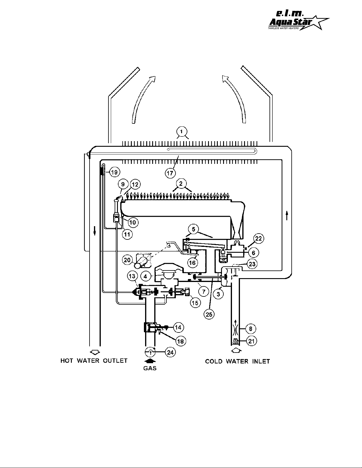
DIAGRAMATIC LAYOUT
1. HEAT EXCHANGER
2. BURNERS
3. WATER FLOW RESTRICTOR
4. FLOW IGNITION DEVICE (LPG ONLY)
5. THERMOSTATIC GAS FLOW MODULATOR
6. GAS FLOW VALVE (THERMOSTATIC CONTROLLED)
7. GAS FLOW VALVE (WATER FLOW CONTROLLED)
8. COLD WATER INLET AND BUILT IN FLOW
CONTROL (REMOVABLE)
9. PILOT LIGHT
10 . PILOT LIGHT ORIFICE
1 1 . PILOT LIGHT GAS FILTER
12 . THERMOCOUPLE
13. ELECTROMAGNET GAS FLOW SHUT-OFF
VALVE
14. MANUAL GAS FLOW SHUT-OFF VALVE
1 5. PILOT STARTER KNOB
16. THERMOSTATIC MODULATOR
ADJUSTING SCREW
23
17. WATER TEMPERATURE PROBE (THERMOSTAT
SENSOR)
18 . GAS LINE PRESSURE TEST NIPPLE
19 . OVERHEAT SENSOR SWITCH
20. THERMOSTATIC WATER TEMPERATURE
SELECTOR
21. WATER FILTER SCREEN
22. GAS PRESSURE TESTING NIPPLE
23. VENTURI PISTON
24 . GAS REGULATOR
25. PUSH ROD ASSEMBLY
Page 24
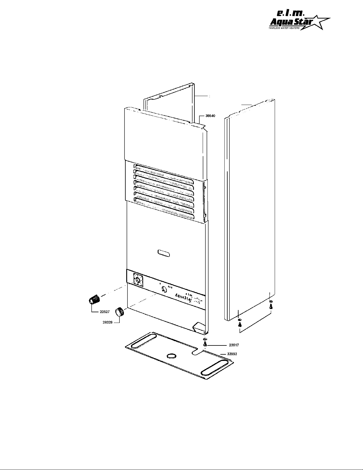
HOUSING COMPONENTS DIAGRAM
AQUASTAR 80
38798
38799
SPARE PARTS LIST
38798 - RIGHT SIDE PANEL
38799 - LEFT SIDE PANEL
22527 - TEMPERATURE
SELECTOR KNOB
23617 - PANEL RETAINING
SCREW
28329 - PILOT STARTER KNOB
24
36540 - FRONT PANEL
33993 - INCANDESCENT
PARTICLE TRAY
Page 25
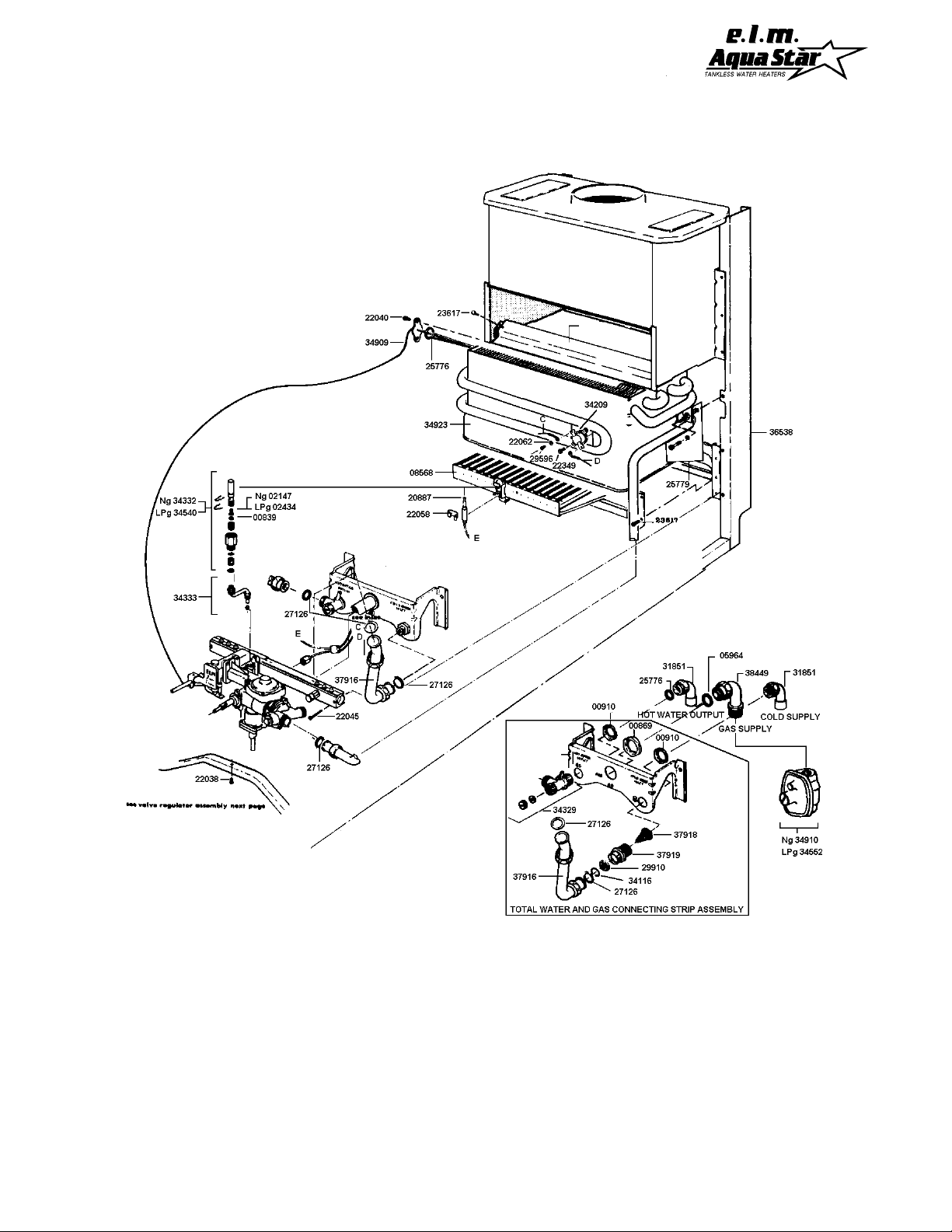
INTERIOR COMPONENTS DIAGRAM
AQUASTAR 80
SPARE PARTS LIST
00839 - PILOT WASHER
00869 - RETAINING NUT FOR GAS INLET FITTING
00910 - RETAINING NUT FOR COLD INLET AND HOT
WATER OUTLET
02147 - NG GAS PILOT INJECTOR
02434 - LP GAS PILOT INJECTOR
05964 - GAS FITTING WASHER
08565 - BURNER ASSEMBLY
20887 - THERMOCOUPLE
22040 - THERMOSTAT SENSING ELEMENT
RETAINING SCREW
22045 - BURNER MANIFOLD RETAINING SCREW
22058 - THERMOCOUPLE RETAINING CLIP
22062 - WASHER
22349 - SCREW
23617 - REAR BURNER SHIELD RETAINING
SCREW
25687 - DRAFT HOOD DEFLECTING STRIP
25776 - WASHER
25779 - HEAT EXCHANGER FRAME RETAINING
SCREW
27126 - WASHER
29596 - THERMOCOUPLE / ELECTROMAGNET
LEAD WIRE TERMINAL RETAINING
SCREW
29910 - INLET WATER FLOW RESTRICTOR
31851 - COLD & HOT WATER ELBOW
34116 - CLIP
34209 - OVERHEAT THERMOSTATIC SENSOR
(ECO)
34296 - WATER & GAS FITTING RETAINING STRIP
25
34316 - FRAME
34329 - HOT WATER RETURN LINE FITTING
34332 - NG TOTAL PILOT ASSEMBLY
34333 - PILOT TUBE ASSEMBLY ("S" TUBE)
34540 - LP TOTAL PILOT ASSEMBLY
34552 - LP GAS REGULATOR
34923 - HEAT EXCHANGER
37916 - WATER VALVE TO COLD INLET CONNECT-
ING COPPER TUBING
37918 - WATER FILTER
37919 - COLD WATER INLET FITTING
38449 - COPPER ELBOW GAS FITTING
Page 26
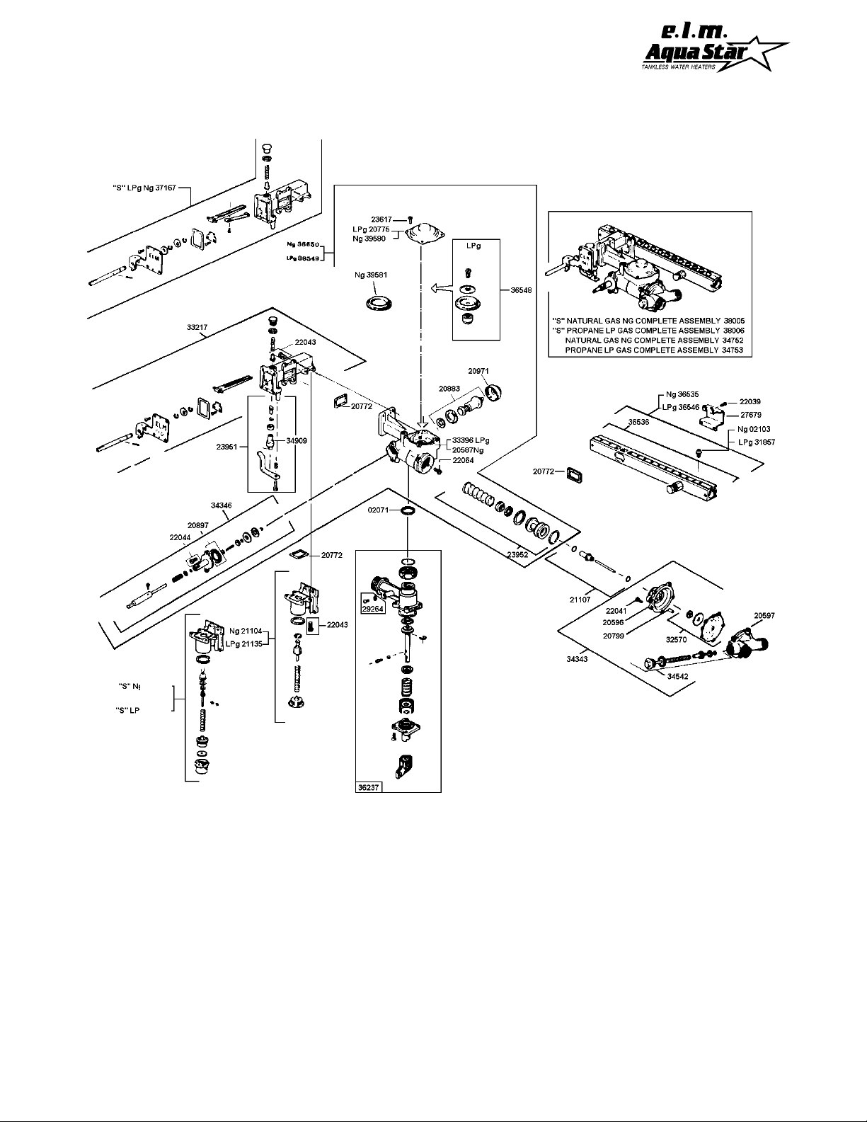
VALVE ASSEMBLY COMPONENTS DIAGRAM
AQUASTAR 80
37613
37614
SPARE PARTS LIST
02071 - MANUAL GAS VALVE GASKET
02103 - INJECTORS - NG
20596 - WATER VALVE COVER
20597 - WATER VALVE HOUSING
20772 - CORK GASKET
20775 - REGULATOR COVER
20799 - CENTERING TUBE
20883 - ELECTROMAGNET WITH WASHER
20897 - THERMOCOUPLE PUSH ROD COVER CORK
WASHER
20971 - ELECTROMAGNET RETAINING COVER
21104 - NG MODULATING THERMOSTATIC VALVE
ASSEMBLY CONNECTOR
21107 - WATER VALVE PUSH ROD
21108 - NG VALVE HOUSING
21135 - LP GAS THERMOSTATIC MODULATING
VALVE ASSEMBLY
22039 - SCREW FOR MANIFOLD CLAMP
22041 - WATER VALVE RETAINING SCREW
22043 - THERMOCOUPLE PUSH BUTTON COVER
RETAINING SCREW
22064 - TIGHTENING SCREW FOR WATER VALVE
23617 - REGULATOR COVER SCREW
23951 - THERMOSTAT SETTING COVER
ASSEMBLY
23952 - GAS VALVE ASSEMBLY
31857 - LP GAS INJECTORS
32570 - WATER VALVE RUBBER MEMBRANE
33217 - THERMOSTAT MODULATING VALVE
ASSEMBLY
34343 - COMPLETE WATER VALVE ASSEMBLY
34346 - THERMOCOUPLE AND ELECTROMAGNET
PUSH BUTTON
34542 - WATER VALVE SPRING LOADED PISTON
26
34752 -NG COMPLETE BLOCK ASSEMBLY
34753 - LP COMPLETE BLOCK ASSEMBLY
36103 - GAS PRESSURE TEST NIPPLE
36535 - BURNER MANIFOLD WITH NG INJECTORS
36536 - GAS MANIFOLD WITHOUT INJECTORS
36546 - BURNER MANIFOLD WITH LP INJECTORS
36548 - LP GAS SLOW IGNITION MEMBRANE
ASSEMBLY
36549 - LP MAIN VALVE ASSEMBLY
36650 - NG MAIN VALVE ASSEMBLY
37167 - MODEL "S" GAS MAIN VALVE ASSEMBLY
37613 - MODEL "S" NG MODULATING THERMO-
STATIC VALVE ASSEMBLY CONNECTOR
37614 - MODEL "S" LP GAS MODULATING
THERMOSTATIC VALVE ASSEMBLY
CONNECTOR
38005 - MODEL "S" NG GAS BLOCK ASSEMBLY
38006 - MODEL "S" LP GAS BLOCK ASSEMBLY
39580 - NG REGULATOR COVER
39581 - O RING
Page 27
INSTINST
INST
INSTINST
ALLAALLA
ALLA
ALLAALLA
TION CHECKLISTTION CHECKLIST
TION CHECKLIST
TION CHECKLISTTION CHECKLIST
Gas Line Size*
Natural Gas
Nominal Iron Pipe Size* 1/2" 3/4" 1"
Model 80 25" 100' 150'
125 NR 40' 125'
17 0 NR 25' 80'
Liquid Propane
Semi-rigid Tubing 1/2" 5/8" 3/4" 7/8"
Model 80 15' 50' 100'
125 NR 20' 50' 100'
17 0 NR NR 35' 70'
*Flex tubing greatly reduces capacity and, therefore, is not recommended.
Minimum Vent Size* and Height
Model Min. Diameter Min. Height Alternative
80 4 " 10' 6' with 5" vent
1 25 5 " 10' 6' with 6" vent
1 70 6 " 10' 6' with 7" vent
*WARNING: Vent size must not be restricted. Installation must comply with
national and local codes.
Water Pressure
For installation on well systems, insure that your water pressure is
between 30 - 50 psi.
27
Page 28

GENERAL
Controlled Energy Corporation (CEC) will furnish a replacement heat
exchanger and will furnish a replacement of any other part, which fails
in normal use and service within the applicable periods specified below,
in accordance with the terms of this warranty. The CEC replacement
will be warranted for the unexpired portion of the original warranty.
This warranty will be valid only for water heaters in the possession of
the original consumer purchaser as recorded on the warranty card.
THE HEAT EXCHANGER
If the Heat Exchanger fails within TEN (10) years after the original
installation and operation, CEC will furnish a replacement heat
exchanger. However, if the water heater is installed in other than a
single family dwelling, or is used as a circulating heater in any
application, this heat exchanger warranty is limited to TWO (2) years
from date of original installation and operation.
ALL OTHER PARTS
If any other part fails within TWO (2) years after original installation
and operation, CEC will furnish a replacement part free of charge.
SHIPPING COSTS
In addition to supplying the replacement part (s), CEC will pay
transportation costs for these parts to a convenient delivery point near
you selected by CEC, such as a local AQUASTAR dealer or distributor .
28
 Loading...