

Page 1

INSTALLATION AND OPERATING
MODELS:
MCA1001 MCA1001M
MCA1501 MCA1501M
MCA2001 MCA2001M
INSTRUCTIONS
MCA SERIES RESIDENTIAL
IRON REDUCTION SYSTEMS
Installer, please leave with homeowner.
Homeowner, retain for future reference.
INSTR2804 0312
Page 2
SAFETY INFORMATION
Read, understand, and follow all safety information contained in these instructions prior to installation and use of the Aqua-Pure® MCA Series Iron Reduction Systems. Retain these instructions for future reference.
Intended use:
The Aqua-Pure MCA Series Iron Reduction Systems are intended for use in reducing dissolved and precipitated iron in water in homes and have not been
evaluated for other uses. These systems are intended for indoor installations near the entry point of a home water line, and must be installed by qualifi ed
professional installers according to these installation instructions.
EXPLANATION OF SIGNAL WORD CONSEQUENCES
WARNING
CAUTION
CAUTION
To reduce the risk associated with choking:
• Do not allow children under 3 years of age to have access to small parts during the installation of this product.
To reduce the risk associated with ingestion of contaminants:
• Do not use with water that is microbiologically unsafe or of unknown quality without adequate disinfection before or after the system.
To reduce the risk of physical injury:
• Shut off inlet water supply and depressurize system as shown in manual prior to service.
To reduce the risk associated with a hazardous voltage:
• If the home electrical system requires use of the cold water system as an electrical safety ground, a jumper must be used to ensure a suffi cient ground connection across
the iron reduction system installation piping — refer installation to qualifi ed personnel.
• Do not use the system if the power cord is damaged — contact qualifi ed service personnel for repair.
To reduce the risk associated with back strain due to the heavy weight of the various system components:
• Follow safe lifting procedures.
Indicates a potentially hazardous situation, which, if not avoided, could result in death or serious injury and/or property damage.
Indicates a potentially hazardous situation, which, if not avoided, may result in minor or moderate injury and/or property damage.
Indicates a potentially hazardous situation, which, if not avoided, may result in property damage.
WARNING
CAUTION
To reduce the risk associated skin, eye, and respiratory tract irritation from gravel and fi lter media during installation:
• Gravel and several types of fi lter media may be used in this product, depending upon the application. During installation, dust may cause irritation to skin, eyes, and
respiratory tract.
• Utilize a NIOSH-approved dust fi lter mask, protective gloves, and appropriate eye protection when handling and pouring gravel and fi lter media.
• To request an MSDS relating to this product, call 203-238-8965 or go to www.3M.com, select country, and use the search engine to search MSDS. For emergen-
cies, call 800-364-3577 or 651-737-6501 (24 hours).
CAUTION
To reduce the risk associated with property damage due to water leakage:
• Read and follow Use instructions before installation and use of this water treatment system.
• Installation and use MUST comply with existing state or local plumbing codes.
• Protect from freezing, relieve pressure and drain system when temperatures are expected to drop below 40°F (4°C).
• Do not install on hot water supply lines. The maximum operating water temperature of this iron reduction system is 100°F (38°C).
• Do not install if water pressure exceeds 100 psi. If your water pressure exceeds 80 psi (552 kPa), you must install a pressure limiting valve. Contact a plumbing
professional if you are uncertain how to check your water pressure.
• Do not install where water hammer conditions may occur. If water hammer conditions exist you must install a water hammer arrester. Contact a plumbing professional if you are uncertain how to check for this condition.
• Where a backfl ow prevention device is installed on a water system, a device for controlling pressure due to thermal expansion must be installed.
• Do not use a torch or other high temperature sources near system.
• On plastic fi ttings, never use pipe sealant or pipe dope. Use PTFE thread tape only, pipe dope properties may deteriorate plastic.
• Take care when using pliers or pipe wrenches to tighten plastic fi ttings, as damage may occur if over tightening occurs.
• Do not install in direct sunlight or outdoors.
• Install system in such a position as to prevent it from being struck by other items used in the area of installation.
• Ensure all tubing and fi ttings are secure and free of leaks.
• SHUT OFF FUEL OR ELECTRIC POWER SUPPLY TO WATER HEATER after water is shut off.
• Do not install system where water lines could be subjected to vacuum conditions without appropriate measures for vacuum prevention.
• Do not apply heat to any fi tting connected to bypass or control valve as damage may result to internal parts or connecting adapters.
• Install on a fl at/level surface. It is also advisable to sweep the fl oor to eliminate objects that could pierce the media tank.
To reduce the risk associated with property damage due to plugged water lines:
• Pay particular attention to correct orientation of control valve. Water fl ow should match arrow on control valve. The Inlet and Outlet of other water treatment
equipment products will vary depending on the control valve brand used.
• Failure to follow instructions will void warranty.
IMPORTANT NOTES
Page 3

TABLE OF CONTENTS
IMPORTANT NOTES
SECTION DESCRIPTION
1 GENERAL INFORMATION
2 BEFORE INSTALLATION
3 INSTALLATION
4 BACKWASHING INSTRUCTIONS
5 MAINTENANCE
6 TROUBLESHOOTING
7 SPECIFICATIONS AND OPERATING DATA
8 LIMITED WARRANTY
SECTION 1: GENERAL INFORMATION
®
Congratulations on your purchase of an Aqua-Pure
dissolved, precipitated and bacterial iron from your water supply. Contrary to conventional methods, your Aqua-Pure MCA Series Iron Reduction System
requires NO chemicals (either added to the water supply or the fi lter). This unique process requires ONLY periodic backwashing for a few minutes to fl ush
out entrapped iron that has accumulated in the media tank.
When properly installed, the Aqua-Pure MCA Series Iron Reduction System will provide many years of virtually trouble-free service. Read this manual all
the way through fi rst, and then follow the instruction steps in the proper sequence.
MCA Series Iron Reduction System! The Aqua-Pure MCA Series Iron Reduction System reduces
Description and Operation of the System:
The Aqua-Pure MCA Series Iron Reduction System consists of two major components which are:
1) A HYDRO-CHARGER located between the well head and the pressure tank, which adds a small amount of air to the iron-laden water whenever the
well pump runs.
2) A backwashing type fi lter containing a special media that causes the iron in the “Hydro-Charged” water to precipitate throughout the media bed (rather
than on the surface as in chemical oxidizing fi lters). This process produces an iron reduction capacity of 30,000 to 50,000 parts per million (ppm) compared to 6,000 to 8,000 ppm for chemical oxidation processes. The media DOES NOT require a chemical regenerant (such as potassium permangante)
for oxygen enrichment, salt, chlorine or any other chemicals.
Your Iron Reduction System automatically adjusts the pH to neutral or higher on acid water WITHOUT an acid neutralizer (a required piece of equipment
with chemical oxidation fi lters whenever the pH is less than 6.7). The ability to raise pH when it is below neutral (7 or less) greatly enhances the MCA
Series Iron Reduction System’s ability to reduce iron effi ciently.
IMPORTANT NOTES
Replenishment of the component of the fi lter media that adjusts pH, “ph-Plus®”, may be required periodically, the frequency of which is dependent on
the raw water pH, the manganese (Mn) concentration in the water (if any) and the water consumption rate.
Periodic backwashing of the media bed fl ushes the precipitated iron to the drain and readies the fi lter for use again. The duration of the backwash
procedure will vary depending on several factors, but generally totals just 10 minutes (factory setting). The frequency of backwashing depends on iron
concentration and water usage, and ranges from daily to once every 12 days. The volume of water consumed during the entire backwashing procedure
is approximately 50 gallons (1 cu. ft. models).
1-1
Page 4

CAUTION
SECTION 2: BEFORE INSTALLATION
Inspecting And Handling Your Iron Reduction System:
Inspect the equipment for shipping damage. If damaged, notify the transportation company and request a damage inspection.
Handle the fi lter unit with care. Damage can result if dropped or if set on sharp, uneven projections on the fl oor. Do not turn the fi lter unit upside down.
CAUTION
To reduce the risk associated with property damage due to water leakage:
• Installation must comply with existing state or local plumbing codes.
Make Sure Your Water Has Been Thoroughly Tested:
An analysis of your water should have beeb made prior to the selection of your water conditioning equipment. Your dealer should have performed this service
for you, and may send a sample to the factory for analysis and recommendations.
Check Your Pumping Rate and Water Pressure:
Two water system conditions must be checked carefully to avoid unsatisfactory operation or equipment damage:
1) MINIMUM water pressure required at the iron reduction system inlet is 20 psi (138 kPa).
CAUTION
To reduce the risk associated with property damage due to water leakage:
• Do not install if water pressure exceeds 100 psi. If your water pressure exceeds 80 psi (552 kPa), you must install a pressure limiting valve. Contact a plumbing professional if you are uncertain how to check your water pressure.
NOTE: Call your local water department or plant operator to obtain pressure readings. If you have a private well, the gauge on the pressure tank will
indicate the high and low system pressure. Record your water pressure data below:
Water Pressure:
Low psi High psi
CAUTION
To reduce the risk associated with property damage due to water leakage:
• Do not install system where water lines could be subjected to vacuum conditions without appropriate measures for vacuum prevention.
The installer is required to take appropriate measures if there is the possibility a vacuum condition may occur. This would include the installation
of an appropriate device in the supply line to the system, i.e., a vacuum breaker or backfl ow prevention device. Vacuum damage voids the factory
warranty.
2) The pumping rate of your well must be suffi cient for satisfactory operation and BACKWASHING of the iron reduction system. (See Specifi cations
And Operating Data, Section 7).
IMPORTANT NOTE
If sediment is present, the installation of a sediment pre-fi lter is recommended. Even if sediment is not currently present or at a level high enough to
be objectionable, a pre-fi lter can help increase the effi ciency of the softener and help reduce the amount of maintenance required.
2-1
Page 5
To measure the pumping rate of your pump, follow these instructions:
IMPORTANT NOTE
a. Make certain no water is being drawn. Open spigot nearest pressure tank. When pump starts, close spigot and measure time (in seconds) to refi ll
pressure tank (when pump shuts off). This fi gure represents CYCLE TIME.
b. With the pressure tank full, draw water into a container of known volume, measure the number of gallons drawn until the pump starts again. This
is DRAW-DOWN. Divide this fi gure by CYCLE TIME and multiply the result by 60 to arrive at the PUMPING RATE in gallons per minute (gpm). To aid in
your calculation, insert the data in the following formula:
DRAW-DOWN ______ (gals.) ÷ CYCLE TIME ______ (secs.) x 60 = PUMPING RATE ______(gpm)
EXAMPLE:
CYCLE TIME is 65 secs.; DRAW-DOWN is 6 gals.; then PUMPING RATE equals: 6 gals. ÷ 65 secs. x 60 = 5.5 gpm
IMPORTANT NOTE
The addition of the Hydro-Charger to the pumping system or plumbing and other water treatment devices (such as an acid neutralizer) may reduce the
fl ow rate at the fi lter drain to an inadequate level to properly backwash the fi lter. If you are uncertain whether your fl ow rate is adequate, contact your
dealer BEFORE installing your MCA Series Iron Reduction System, so that corrective action, if required, may be taken.
Installation Site Selection:
Select the location of your iron reduction system with care. Various conditions which contribute to proper location are as follows:
1) Locate as close as possible to water supply source.
2) Locate as close as possible to a drain.
3) Locate in correct relationship to other water conditioning equipment (Figure 1, page 3-1).
4) Locate the iron reduction system in the supply line BEFORE the water heater. Temperatures above 100°F (38°C) will damage the iron reduction
system and void the factory warranty.
5) DO NOT install the iron reduction system in a location where freezing temperatures occur. Freezing may cause permanent damage and will also
void the factory warranty.
6) Allow suffi cient space around the installation for easy servicing.
7) Provide a non-switched 110V, 60Hz power source for the control valve.
WARNING
To reduce the risk associated with ingestion of contaminants:
• Do not use with water that is microbiologically unsafe or of unknown quality without adequate disinfection before or after the system.
CAUTION
To reduce the risk associated with property damage due to water leakage:
• Protect from freezing, relieve pressure and drain system when temperatures are expected to drop below 40°F (4°C).
• Do not install on hot water supply lines. The maximum operating water temperature of this iron reduction system is 100°F (38°C).
• Do not install in direct sunlight or outdoors.
2-2
Page 6
The Importance Of Your Pressure Tank:
IMPORTANT NOTES
IMPORTANT NOTE
The pressure tank found on private well systems becomes an integral part of the MCA Series Iron Reduction System by providing necessary mixing and
“residence time” to the “Hydro-Charged” water. While the MCA Series Iron Reduction System will perform satisfactorily with either a captive-air (bladder)
type pressure tank or a standard air-to-water type with an air volume control (air-relief valve), the bladder type requires more careful adjustment of the
Hydro-Charger to prevent gases from collecting in the pressure tank and the head area of the media tank.
IMPORTANT NOTES
A properly sized pressure tank of either style will require a minimum pump cycle of 60 seconds to refi ll from the well pump on-to-off pressure settings.
If cycle time of pump is less than 60 seconds, pressure tank is too small, causing excessive wear on the pump and probable failure of the fi lter system.
Under more severe operating conditions (low pH, high iron, manganese and small concentrations of sulfur), a standard air-to-water type pressure tank
with an air-relief valve MUST be used (if bladder type tank is already in place, do not remove it. Install the air-to-water pressure tank between the HydroCharger and the bladder type-tank).
IMPORTANT NOTE
If your pressure tank (or any part of your water system) is not functioning properly, corrective action MUST be taken BEFORE installation of your MCA
Series Iron Reduction System.
Facts to Remember While Planning The Installation:
1) All installation procedures MUST conform to local and state plumbing codes.
2) If lawn sprinklers, a swimming pool, or geothermal heating/cooling or water for other devices/activities are to be treated by the iron reduction
system, a larger model MUST be selected to accommodate the higher fl ow rate plus the backwashing requirements of the iron reduction system.
Consult your Dealer/Installer or our Customer Service Department at 1-800-222-7880 for alternative instructions if the pumping rate is insuffi cient.
3) Remember that the iron reduction system INLET is attached to the pipe that supplies water (i.e. delivers water from the well pump or after the
water meter) and the OUTLET is the line that runs toward the water heater.
CAUTION
To reduce the risk associated with property damage due to plugged water lines:
• Pay particular attention to correct orientation of control valve. Water fl ow should match arrow on control valve. The Inlet and Outlet of other water treatment
equipment products will vary depending on the control valve brand used.
4) Before beginning the installation review the existing piping system and to determine the size, number and type of fi ttings required.
WARNING
To reduce the risk associated with a hazardous voltage:
• If the home electrical system requires use of the cold water system as an electrical safety ground, a jumper must be used to ensure a suffi cient ground connec-
tion across the iron reduction system installation piping — refer installation to qualifi ed personnel.
5) Sweep the fl oor to eliminate objects that could pierce the media tank.
2-3
Page 7
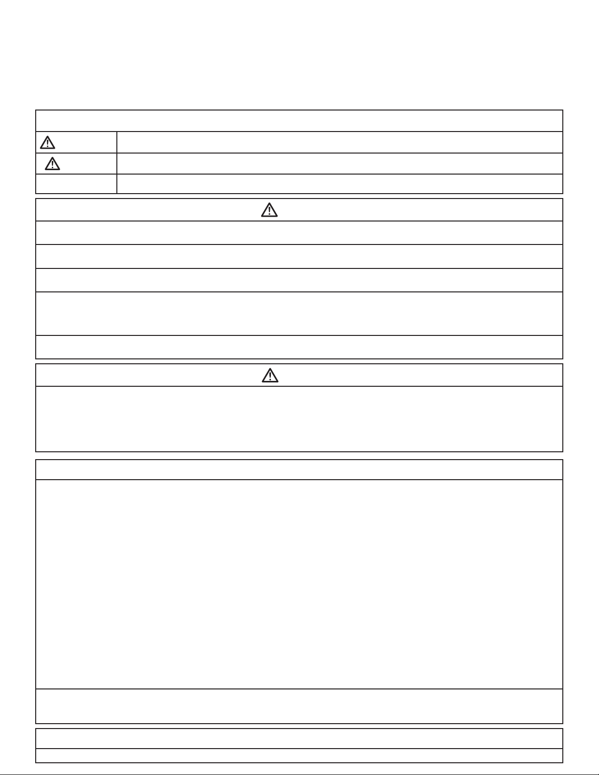
SECTION 3: INSTALLATION
Proper installation sequence of Iron Reduction System is very important. Refer to the diagram before for your particular supply.
TREATED
SOFT WATER
BRINE
TANK
TREATED
SOFT WATER
TREATED WATER
BRINE
TANK
WATER
SOFTENER
TREATED WATER
WASTE DRAIN
IRON
REDUCTION
SYSTEM
PRESSURE
WATER
SOFTENER
WASTE DRAIN
REDUCTION
WASTE DRAIN
IRON
SYSTEM
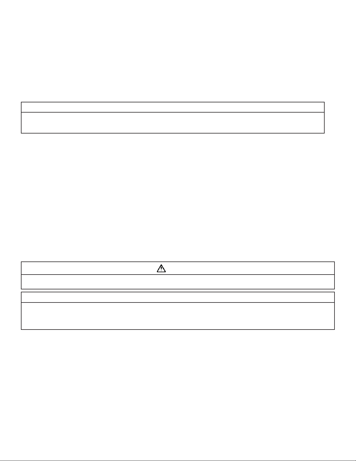
TYPICAL WELL INSTALLATION
TO
110 V
OUTPUT
WASTE DRAIN
SECONDARY
PRESSURE
TANK
SECONDARY
PRESSURE
SWITCH.
SOLENOID
HYDRO-CHARGER
TYPICAL SPLIT-STREAM INSTALLATION
TANK
PRESSURE
SWITCH.
LAWN SPRINKLERS
HIGH DEMAND
VALV E
WATER FOR
OR OTHER
PRESSURE
CHECK VALVE
HYDRO-CHARGER
CHECK VALVE
PRIMARY
TANK
PRESSURE
PRIMARY
SWITCH.
RAW
WELL
WATER
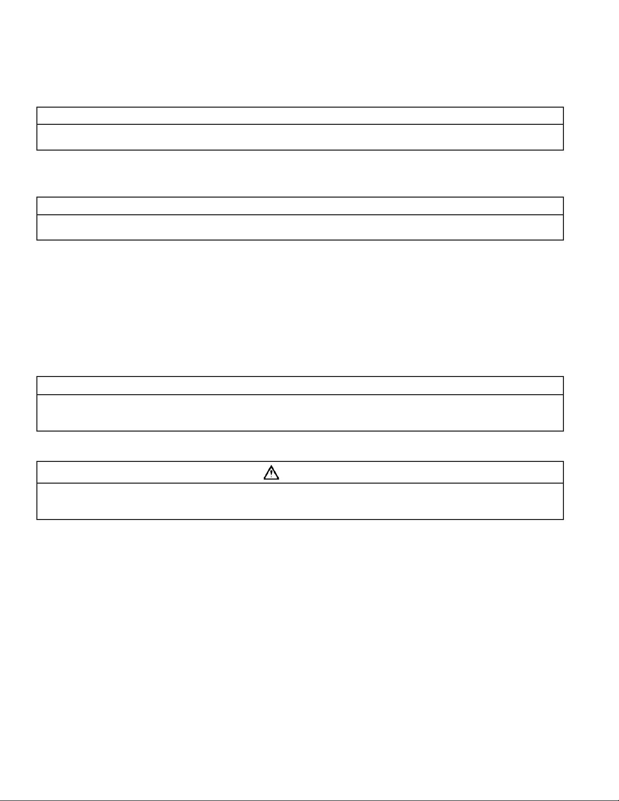
RAW
WELL
WATER
TREATED
SOFT WATER
BRINE
TANK
TREATED WATER
WATER
SOFTENER
WASTE DRAIN
IRON
REDUCTION
SYSTEM
WASTE DRAIN
PRESSURE
PRESSURE
SWITCH.
TANK
TO
110 V
OUTPUT
SOLENOID
VALV E
HYDRO-CHARGER
WATER FOR
LAWN SPRINKLERS
OR OTHER
HIGH DEMAND
CHECK VALVE
METER
RAW
WATER
TYPICAL PUBLIC WATER SUPPLY INSTALLATION
Figure 1
CAUTION
To reduce the risk associated with property damage due to water leakage:
• Read and follow Use instructions before installation and use of this water treatment system.
• Installation and use MUST comply with existing state or local plumbing codes.
To reduce the risk associated with property damage due to plugged water lines:
• Pay particular attention to correct orientation of control valve. Water fl ow should match arrow on control valve. The Inlet and Outlet of other water treatment
equipment products will vary depending on the control valve brand used.
3-1
Page 8
Step 1
CAUTION
IMPORTANT NOTES
IMPORTANT NOTE
Shut off all water at main supply. On a private well system, turn off power to pump and drain pressure tank. Make certain pressure is relieved from
complete system by opening nearest faucet to drain system.
CAUTION
To reduce the risk associated with property damage due to water leakage:
• When water supply is shut off, shut off fuel or electric power to water heater.
Step 2
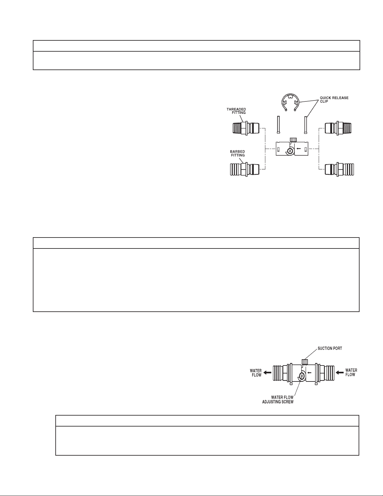
Cut main supply line as required to fi t Hydro-Charger in plumbing between well pump and pressure tank (Hydro-Charger may be installed in a vertical
or horizontal position). The Hydro-Charger has been supplied with both 1” threaded
and 1” barbed (insert) fi ttings to allow for installation with various types of piping
materials. When using the threaded nipples, use thread tape only. When using barbed
(insert) fi ttings, appropriate pipe clamps must be used. Once installed, the quick release nipples allow the Hydro-Charger to be rotated, so the air draw adjustment screw
is accessible for adjustment by a small bladed screwdriver. Allow at least 10 inches of
straight run of 1” pipe on both inlet and outlet side of the Hydro-Charger. Refer to Figure 2 for correct assembly. The quick release nipples also acts as a union to facilitate
the Hydro-Charger removal, inspection and cleaning as needed. With an installation on
PVC pipe and copper tubing it may require the addition of a normal plumbing union to
aid in removal from the plumbing due to the rigidity of that type of material. Make certain the directional arrows on the Hydro-Charger points toward the pressure tank and
the pressure control switch is located on the pressure tank side of Hydro-Charger as
in Figure 1. Rapid cycling of pump may occur if the pressure control switch is located
on well side. If a check valve is located between Hydro-Charger and pressure tank,
it may prevent the Hydro-Charger from performing properly. Relocate to well side of
Hydro-Charger.
Figure 2: HYDRO-CHARGER INSTALLATION
Step 3
Turn back on the power to the well pump and pressurize the water lines to allow for adjustment of the Hydro-Charger. Check for leaks and adjust as
necessary.
IMPORTANT NOTES
• Do not apply heat near Hydro-Charger, as damage may occur. On badly scaled, older plumbing systems, it may be advantageous to install a WYE
Strainer to help prevent plugging of the Hydro-Charger nozzle with scale or debris. The use of a WYE Strainer must precede the Hydro-charger
on the inlet side by a minimum of 10”.
• If existing water system includes a captive-air type pressure tank (bladder) and it is desirable to install an additional air to water type with an air
release (not as a split steam type installation) install an air to water type pressure tank between the Hydro-Charger and the existing captive air
type pressure tank.
• Before proceeding with Hydro-Charger installed, re-verify adequate pumping rate pumping by following the procedure described in Section
2. After verifi cation of adequate fl ow, depressurize system as described previously.
• If installation is to be split streamed prior to fi lter vessel or is a public water supply see Figure 1, or refer to Special Instructions on page 3-5.
Step 4
Set Hydro-Charger by following these steps:
a) Open nearest faucet until well pump starts, then close faucet.
b) Place a fi nger lightly over the suction port (Figure 3). A slight suction should be de-
tected for approximately one third (1/3) of pumping cycle time. (Do not confuse with
one third (1/3) of pressure range).
c) If suction is too short, increase by turning air adjustment screw (Figure 3), clockwise.
To decrease duration, turn counterclockwise.
d) Repeat steps (a) through (c) until proper setting is obtained. The optimum cycle time
is 60 seconds or more, with an air draw of 20 seconds minimum.
Figure 3
IMPORTANT NOTE
When the duration of the suction is too long, the cold water may have a milky appearance caused by excess air in the water system. Correct this condition by reducing the duration of suction. This condition is commonly associated with bladder type pressure tanks. In extreme
cases where elimination of excess air prevents system from performing satisfactorily, it may be necessary to install an air to water pressure
tank with an air release valve.
3-2
Page 9

Step 5
CAUTION
If media is already in the media tank proceed to Step 6.
If media is shipped separately, follow these steps to center the distributor tube and load the fi lter media into the media tank to ensure the successful
installation of your MCA Series Iron Reduction System.
a. Remove the control valve by rotating the valve head assembly to the left or counter-clockwise and set aside to reassemble after media is loaded into
the tank.
b. Tilt media tank to a 45 degree angle until gravel shifts to the side of the tank and dimple at bottom of media tank is visible. This will allow you to place the
distributor tube basket assembly in the dimple on the bottom of the media tank.
c. Place media tank back in upright position and ensure gravel at the bottom of the media tank is level. Place centering tool on the distributor tube that is pro-
vided in the parts bag.
d. Locate the fi lter media that will be used in the iron reduction system and load into the media tank. Note: Never add media above line indicated on
side of tank. You may have received more media than required for the initial fi ll, save extra media for future replenishment. When fi nished adding
media, remove centering tool. Using a pail or garden hose slowly fi ll the media tank to the top to displace any air from the tank. Use a clean rag to
wipe the opening of the media tank to remove any dust or sediment before moving to the next step.
e. Place the control valve on top of the media tank. Engage the threads of the control valve into the threads of the media tank. Turn the valve clockwise
until it seats onto the media. Ensure a water tight seal by turning the valve another quarter turn.
CAUTION
To reduce the risk associated skin, eye, and respiratory tract irritation from gravel and fi lter media during installation:
• Gravel and several types of fi lter media may be used in this product, depending upon the application. During installation, dust may cause irritation to skin, eyes,
and respiratory tract.
• Utilize a NIOSH-approved dust fi lter mask, protective gloves, and appropriate eye protection when handling and pouring gravel and fi lter media.
• To request an MSDS relating to this product, call 203-238-8965 or go to www.3M.com , select country, and use the search engine to search MSDS. For emergencies, call 800-364-3577 or 651-737-6501 (24 hours).
Step 6
Turn off the electrical source to the water well pump or the close the water shut off
valve on a municipal water supply to the dwelling once again. Depressurize the water
system by opening the nearest faucet to drain water from the water system in order to
allow the installation of the MCA Series Iron Reduction System.
Step 7
Determine location and cut the water line on the supply side of the pressure tank as
required to fi t the plumbing to the control valve connection fi ttings. You may want to install a separate three valve bypass prior to the control valve in case the supplied bypass
valve requires maintenance in order to provide undisturbed water use.
YOKE
CONTROL VALVE BODY
FILL PORT
ADAPTER
OUT
Step 8
Assemble and attach bypass valve to the control valve. See Figure 4 if needed. Make
certain the water enters inlet and discharges through the outlet side of the bypass
valve. Arrows can be viewed on the bypass valve to confi rm the correct fl ow path.
At this time make certain the bypass valve is in the bypass position and leave in that
position until instructed to place in the service position. Refer to Figure 4 for proper
operation.
SERVICE
ROTATE
KNOBS
Figure 4 . INLET/OUTLET CONNECTIONS
CAUTION
To reduce the risk associated with property damage due to water leakage:
• Do not use torches or other heat sources near plastic plumbing, as damage may occur.
• Take care when using pliers or pipe wrenches to tighten plastic fi ttings, as damage may occur.
• On plastic fi ttings, use thread sealing tape only. Never use pipe sealant or pipe dope on plastic fi ttings, as damage may occur.
IN
BYPASS
BYPASS
BYPASS VALVE
CLIP & SCREW
FLAT CAP
DRAIN LINE
ELBOW
FLOW CONTROL ASSEMBLY
SET SCREW
BYPASS
Step 9
Loosen set screw and pull out drain line fl ow control (DLFC) assembly from valve body (see Figure 4). Unscrew drain line elbow from DLFC. Apply PTFE
tape to threads. Reassemble to valve body, making certain DLFC assembly is fully inserted into valve body before tightening set screw.
Attach drain line to drain line fi tting. To prevent back pressure from reducing fl ow rate below minimum required for backwash, drain line must be sized
according to run length and relative height. Be careful not to bend fl exible drain tubing sharply enough to cause “kinking” (if kinking occurs drain line
MUST be replaced!).
3-3
Page 10

Typical examples of proper drain line diameters are:
IMPORTANT NOTES
1 )1/2 in. ID up to 15 ft. when discharge is lower than inlet.
2) 5/8 in. ID up to 15 ft. when discharge is slightly higher than inlet.
3) 3/4 in. ID when drain is 25 ft. away and/or drain is installed overhead.
Some areas prohibit the use of fl exible drain lines. Check with local code offi cials prior
to installation.
Step 10
Position the drain line over the waste drain pipe and secure fi rmly. To prevent back siphoning of sewer water or grey water, provide an air gap of at least two inches or 2 times
the pipe diameters between the end of drain line tubing and waste drain (Figure 5). Do
not raise the drain line more than 10 feet above the fl oor. Check with local code offi cials
to ensure you conform to local, state and national plumbing codes.
EQUIPMENT
DRAIN LINE
AIR GAP
2" REF.
DRAIN
Step 11
Open the valve on the water supply as required to pressurize the water lines to the dwelling or fuel source. The power to the water heater or boiler needs to be established once water has been allowed to fl ow back into the device, if it was
drained at any time during the installation. Plug the control valve into a properly grounded 110/120V 60 Hz non switched electrical outlet. Check with
your local code enforcement offi ce to determine if it meets local codes.
Figure 5. DRAIN
Step 12
Turn back on the power source to well pump and slowly open the shut off valve to pressurize the water system. If on a public or community water supply
open the main shut off valve to the dwelling.
Step 13
Set the time of day by referring to Page 4-3 “How To Set The Time-Of-Day”.
Step 14
Check for leaks on all connections, correct as required.
Step 15
Manually initiate backwash of the Iron Reduction System by referring to the “How To Manually Backwash Your Filter At Any Time” on page 4-3.
Step 16
Once the valve is in the backwash position slowly open the inlet side of the bypass valve to allow water to fl ow into the fi lter vessel. Water should start
to fl ow into the drain. Allow for any air that might have been trapped to leave the fi lter and go to drain. This will be detected by changes in noise in the
drain line or is visible in the semi-transparent tubing. Once the air is entirely gone slowly increase the water fl ow to drain by opening the inlet side of the
bypass valve until fully open. Refer to Figure 4 for correct positioning. At the end of fi lling, the water should be clear. If not, allow the valve to complete
the manual backwash process and initiate once again. It is very important to allow the unit to purge all fi nes from the media in the fi lter vessel to the
waste drain prior to using the water. Once the fl ushing process has been completed you now can open the outlet side of the bypass valve to allow for
fi ltered water to fl ow into the dwelling.
IMPORTANT NOTES
Due to the nature of the MCA Series Iron Reduction media, on start up it sometimes requires 2 or 3 days for the Aqua-Pure® MCA Series Iron Reduction
System to reduce Iron and Manganese below staining levels. Do not be alarmed if this occurs. During the initial start up and subsequent fi rst couple
automatic backwash cycles, a small amount of fi ne white and beige media may be observed in the drain water and or drain area. This is normal and
benefi cial for the effi cient operation of your Aqua-Pure MCA Series Iron Reduction System.
Step 17
The frequency of backwash is factory preset at every 4 days. If the iron content is greater than 5 ppm, is red water or bacterial iron, the unit should be
washed more frequently. See tables to determine the frequency. Also if the water has tannin-lignin or hydrogen sulfi de present, the fi lter should backwash every day. Refer to Section 4 for backwashing instructions and frequency.
INSTALLATION IS NOW COMPLETE AND SYSTEM IS READY FOR SERVICE
3-4
Page 11

SPECIAL INSTRUCTIONS FOR SPLIT-STREAM AND
IMPORTANT NOTE
PUBLIC WATER SUPPLY TYPE INSTALLATIONS:
For split-stream type installations, a secondary pressure tank must be installed as in Figure 1. On public water supply type installations, a pressure tank
must be installed as in Figure 1.
The pressure tank should be of same capacity as would normally be installed if water system were a standard private well type. Also note both applications require a normally-closed solenoid valve. Follow standard installation procedures above with following additions and modifi cations.
1) Install pressure tank (See Figure 1) or secondary pressure tank (See Figure 1) as indicated by appropriate diagram.
2) Install normally-closed solenoid valve, 110/120V, 60Hz after water meter on public water supply installations or after a line split for untreated water
on split stream installations.
3) On both types installation, install hyrdo-charger between pressure tank (secondary pressure tank on split-stream type installation) and normallyclosed solenoid valve.
4) Install pressure switch after hydro-charger and wire it to solenoid valve (secondary pressure switch on split-stream). Set high pressure on pressure
switch (which controls opening and closing of solenoid valve) 2 to 3 psi lower than low pressure on primary pressure switch. EXAMPLE: if primary
pressure switch is set at 40/60 psi, set secondary pressure switch 20/38 psi.
For public water supply type installations, contact your local water department or plant operator and ask what the normal low system pressure is. Set
high pressure on pressure switch 2 to 3 psi lower than this fi gure.
IMPORTANT NOTE
Failure to set pressure switch as described above will not allow proper closing of solenoid valve during periods of low system pressure. Improper
function of solenoid valve will cause total failure of system.
Replenishing Media:
CAUTION
To reduce the risk associated skin, eye, and respiratory tract irritation from gravel and fi lter media during installation:
• Gravel and several types of fi lter media may be used in this product, depending upon the application. During installation, dust may cause irritation to skin,
eyes, and respiratory tract.
• Utilize a NIOSH-approved dust fi lter mask, protective gloves, and appropriate eye protection when handling and pouring gravel and fi lter media.
• To request an MSDS relating to this product, call 203-238-8965 or go to www.3M.com , select country, and use the search engine to search MSDS. For
emergencies, call 800-364-3577 or 651-737-6501 (24 hours).
1) Pressure must be relieved on water treatment system by turning the bypass valve to the bypass position. Then initiate an immediate manual backwash cycle as described on Page 4-3.
2) Disconnect the power cord from the electrical outlet.
3) Remove the drain line from the control valve. Remove the control valve by rotating the valve head assembly to the left or counter-clockwise and set
aside to reassemble after media is loaded into the tank.
4) Insert fl exible tubing down the distributor tube and siphon the water from the media tank to aid in adding or replacing fi lter media. Remove fl exible
tubing. Cover the distributor tube with centering tool to prevent media from entering the distributor tube. Add the media you are using to the line on
the side of the media tank. Remove centering tool. Then refi ll the media tank with water utilizing a hose or clean bucket. Dispose of spent media in
accordance with federal, state, and local regulations.
5) Prior to reattaching valve head assembly to the tank, inspect the o-ring for wear. If none, lubricate with silicone grease or water. Reattach valve head
assembly by rotating to the right or clockwise until valve head assembly is seated to the tank hand tight.
6) Reattach the bypass valve to the control valve and slowly open the bypass. Allow the iron reduction system pressurize and set for the required time
period.
7) Plug the control valve into the electrical outlet and set the time of day on the display.
8) Once the saturation time has been achieved, manually initiate an immediate backwash (see Page 4-3). Backwash the media until the water runs
clear. Observe the color of the water in the drain line discharge to determine if is has washed long enough. The water should be fairly clear and
absent of fi nes before quitting the cleaning process. If not, proceed to regenerate the unit again until the water runs clear to the waste drain.
9) Re-bedding of media tank is now complete.
3-5
Page 12

Draining Water From Filter:
IMPORTANT NOTE
1) Stage program wheel on control valve powerhead to backwash position to relieve pressure.
IMPORTANT NOTE
Lift end of drain line to retain water in the line. DO NOT allow drain line to empty. If drain connection is to a rigid pipe, disconnect it at the drain
line fl ow control and attach a length of fl exible tubing for this operation.
2) Stage program wheel to space between backwash and rapid rinse.
3) Lower end of drain line. Filter will now siphon itself empty of water. You can terminate the siphoning action at any time by staging the control valve
to service position.
3-6
Page 13

SECTION 4: BACKWASHING INSTRUCTIONS
Periodic backwashing of the Aqua-Pure® MCA Series Iron Reduction System bed is required to fl ush out the entrapped iron that has accumulated. This
procedure is performed automatically at 1:00 a.m. for a period of approximately 10 minutes, and will not interfere with a standard softener regeneration
cycle which is usually set for 2:00 a.m.
To Set Backwash Frequency:
To determine and set backwash frequency, follow these instructions:
1) Select backwashing frequency schedule corresponding to your model.
2) Locate box intersected by number of persons in your family and iron concentration of water (if iron concentration is between two numbers in sched-
ule, use higher number.)
3) Number in box represents number of times, in 12 days, timer should be set to regenerate. Refer to “How To Set Time Control” (page 4-3) to set timer.
Example: You have a 1 cubic foot Iron Reduction System, 4 in family and 8 ppm iron. Refer to schedule and locate box intersected by 4 in family and
8 ppm iron. The fi gure “1” in box indicates a backwash frequency of one time per 12 days (if a “2,” “3,” or “4” were in box, frequencies of twice,
three times and four times per twelve days respectively would be indicated.)
NOTE: The backwashing frequency schedules are based on average water consumption rates and are merely guides. They are NOT intended to be
used if water used by outside spigots, a swimming pool, geothermal heat pump, or other high water usage devices or activities are to be treated by
your MCA Series Iron Reduction System. If your application includes any of these, and you have already determined your MCA Series Iron Reduction
System is capable of handling the fl ow rates involved, refer to the next paragraph for instructions on setting backwash frequency.
If your water contains a high iron concentration, manganese, tannins or hydrogen sulfi de it may be advisable to increase the backwash frequency up to
daily, if necessary. It should be noted, however, that increasing the frequency or duration of backwashing WILL NOT overcome an insuffi cient pumping
rate.
4-1
Page 14

BACKWASHING FREQUENCY SCHEDULES
MCA1001, MCA1001M
Persons in
Family
1 1111111111
2 1111122222
3 1122223333
4 1122233444
5 1122334466
6 1223346666
2468101214161820
MODELS: MCA1501, MCA1501M
Persons in
Family
1 1111111111
2 1111112222
3 1111222333
4 1212223344
5 1212233446
6 1222333466
7 22333466612
8 233346661212
2468101214161820
IRON CONTENT - (PPM)
IRON CONTENT - (PPM)
MODELS: MCA2001, MCA2001M
Persons in
Family
1 111111111111
2 111111122222
3 111222222233
4 112222233333
5 122223333444
6 122333344466
7 123334446666
8 123344466666
9 23344466661212
10 234446666121212
5 1012141618202224262830
IRON CONTENT - (PPM)
4-2
Page 15

SERVICE
POSITION
INDICATOR.
HOW TO SET TIME CONTROL
24 HOUR GEAR.
MANUAL BACKWASH KNOB.
TO SET TIME OF DAY-
4
AM
6
PRESS RED BUTTON AND
TURN LARGE DIAL UNTIL
3
TIME IS AT ARROW.
2
1
9
8
7
TO MANUALLY
START CYCLE-
TURN KNOB
CLOCKWISE.
12
11
10
6
7
9
10
11
12
5
6
7
PM
8
9
10
11
12
1
2
5
4
3
2
1
TIME
3
4
of DAY
5
5
6
7
PM
8
9
10
11
12
1
2
3
TIME
of DAY
4
5
4
AM
6
TO SET TIME OF DAYPRESS RED BUTTON AND
TURN LARGE DIAL UNTIL
3
TIME IS AT ARROW.
2
1
9
8
7
TO MANUALLY
START CYCLE-
TURN KNOB
CLOCKWISE.
12
11
10
6
7
9
10
11
12
5
4
3
2
1
POINTER
RED TIME
SET BUTTON.
SKIPPER WHEEL.
(SHOWS EVERY OTHER DAY
BACKWASHING.)
SCREW
HOW TO SET DAYS ON WHICH FILTER TO BACKWASH:
Rotate the skipper wheel until the number “1” is at the red pointer. Set the days that backwash is to occur by sliding tabs on the skipper wheel outward
to expose trip fi ngers. Each tab is one day. Finger at red pointer is tonight. Moving clockwise from the red pointer, extend or retract fi ngers to obtain the
desired backwashing schedule:
HOW TO SET THE TIME-OF-DAY:
1) Press and hold the red button in to disengage the drive gear.
2) Turn the large gear until the actual time of day is opposite the time of day pointer. Unit will now be set to backwash at 1:00 a.m. (See below to adjust
this time.)
3) Release the red button to again engage the drive gear.
HOW TO MANUALLY BACKWASH YOUR FILTER AT ANY TIME:
Turn the manual backwash knob to the right until the knob engages the program wheel. This slight movement of the knob will start the backwash program.
The backwash knob will make one revolution in approximately three hours and stop in the position shown in the drawing. Even though it takes three hours
for the knob to complete one revolution, the backwash cycle of your unit might be only 12 to 20 minutes in duration.
Filtered water may be drawn after rinse water stops fl owing to drain.
HOW TO ADJUST BACKWASH TIME:
1) Disconnect the power source.
2) Locate the three screws behind the manual backwash knob by pushing the red button in and rotating the 24 hour dial until each screw appears in
the cut out portion of the manual backwash knob.
3) Loosen each screw slightly to release the pressure on the time plate from the 24 hour gear.
4) Locate the backwash time pointer on the inside of the 24 hour dial in the cut out.
5) Turn the time plate so the desired backwash time aligns next to the raised arrow.
6) Push the red button in and rotate the 24 hour dial. Tighten each of the three screws.
7) Push the red button and locate the pointer one more time to ensure the desired backwash time is correct.
8) Reset the time of day and restore power to the unit.
4-3
Page 16

HOW TO SET THE BACKWASH CYCLE PROGRAM:
IMPORTANT NOTE
The backwash cycle program on your fi lter has been factory preset. However,
portions of the cycle or program may be lengthened or shortened in time to suit
local conditions.
To expose cycle program wheel, grasp timer in upper left-hand corner and pull,
releasing snap retainer and swing timer to the right.
To change the backwash cycle program, the program wheel must be removed.
Grasp program wheel and squeeze protruding lugs towards center, lift program
wheel off timer. (Switch arms may require movement to facilitate removal.)
HOW TO CHANGE THE LENGTH OF
THE BACKWASH TIME:
The program wheel as shown in the drawing is in the service position. As you
look at the numbered side of the program wheel, the group of pins starting at
zero determines the length of time that your unit will backwash.
FOR EXAMPLE: If there are three pins in this section, the time of backwash will
be six minutes (2 min. per pin). To change the length of backwash time, add or
remove pins as required. The number of pins times two equals the backwash
time in minutes.
HOW TO CHANGE THE LENGTH
OF RAPID RINSE TIME:
The second group of pins on the program wheel determines the length of time
that your fi lter will rapid rinse (2 min. per pin.)
To change the length of rapid rinse, add or remove pins at the higher numbered
end of this cycle as required (See note below). The number of pins times two
equals the rapid rinse time in minutes.
The backwash cycle is complete when the outer micro-switch drops off the last
pin in the rapid rinse group of pins. The program wheel, however, will continue to rotate until the inner micro-switch drops into the notch on the program
wheel.
IMPORTANT NOTE
There must always be two empty holes between the backwash & rapid rinse cycles for proper cycle staging.
Return program wheel to timer and return timer to closed position engaging snap retainer in back plate. Make certain all electrical wires locate above
snap retainer post.
HOW TO MANUALLY CYCLE PROGRAM:
Manually cycling control is useful when it is desirous to check control functions. Slowly rotate programming wheel counter clockwise until valve drive
motor engages. Release program wheel until motor stops. Control will be in backwash cycle. Continue rotating wheel repeating above procedure and
motor will drive piston to the second (intermediate) position. Repeating procedure will cause motor to drive piston to rapid rinse position. Control may be
returned to service by rotating program wheel to home position (micro-switch lever will drop into notch on program wheel).
4-4
Page 17

SECTION 5: MAINTENANCE
IMPORTANT NOTE
Plumbing System Clean-Up
For your new system to operate properly, you may need to clean the entire plumbing system of the precipitated iron that has collected in it or iron “bleed”
(staining) will continue to be a problem. The plumbing system includes all water treatment equipment (such as iron reduction systems), water heaters, toilets,
and dishwashers. Please refer to the appropriate equipment owner’s manual for instructions.
General Maintenance
Periodic media replenishment will be required if your raw water has a pH below 7 and/or a manganese content over 0.2 ppm. The frequency of replenishment
will depend on raw water pH; hardness; iron; manganese; amount of water used; and the size of the fi lter selected.
Should your raw water have a low pH, it is recommended that you check the media level every 6-12 months. To check the level follow these steps:
1) Place light behind media tank and observe media level. If media is down 2-3 inches below line on side of tank, disconnect control valve from bypass
valve. Remove control valve from media tank by grasping the control valve and turn counter clockwise. Cover the distributor tube with centering tool to
prevent media from entering the distributor tube. Add ph-Plus® and reattach valve. Manually backwash fi lter to mix ph-Plus into media bed.
If you are unable to see through tank with light proceed to #2.
2) Turn bypass valve to “bypass” position.
3) Manually stage fi lter into “backwash” to relieve water pressure.
4) Disconnect control valve from bypass valve. Remove control valve from media tank by grasping the control valve and turn counter clockwise.
5) Using a yard stick, measure media level. Remember media should be down 16-17 inches from the top of the media tank.
6) If media is down 2-3 inches, siphon water from tank and add ph-Plus to return the level to the proper depth.
When the media level is below 20 inches from the tank top, replenish it with the original media blend.
IMPORTANT NOTE
When adding media, cover the distributor tube with centering tool to prevent media from entering the distributor tube.
Over time it is best to schedule maintenance frequently enough so only a couple of bottles of ph-Plus is required to replenish the fi lter. ph-Plus is sold in 3.5
pound bottles by your dealer.
Always backwash fi lter immediately following media replenishment.
Another maintenance step which may be required is resetting the timer to the proper time of day. It may be in error due to power outages and/or changes due
to daylight savings time. This should be checked at least every six months.
Special Service Instructions:
Under normal circumstances removal of the valve should not be required. However, if it must be removed, disconnect the plumbing attached to the bypass valve
fi rst. Then, rotate the valve head assembly to the left or counter-clockwise. Before attempting any disassembly, pressure should be relieved by shutting off water to
the system and opening a faucet. Upon reassembly, all o-rings should be lubricated with silicone grease. Reattach valve head assembly by rotating to the right or
clockwise until valve head assembly is seated to the tank hand tight. Reconnect the plumbing to the bypass valve.
5 -1
Page 18

PROBLEM CAUSE SOLUTION
A. Water clear when drawn,
turns red upon standing
(Stain producing)
B. Water red when drawn
from tap.
C. Excessive pressure loss
through fi lter
D. “Milky” or “bubbly” water
(appears to contain small
bubbles)
E. Filter backwashing at
wrong time of day.
SECTION 6: TROUBLESHOOTING
1. Insuffi cient air-draw by Hydro-Charger. 1. Check Hydro-Charger adjustment. If unable to adjust for
2. Bypass open or leaking.
3. Media bed overloaded with precipitated iron due to
backwash, or failure to backwash due to problem with
control timer or unplugged control valve power cord.
4. Presence of manganese or tannins. 4. Recheck water analysis.
5. Flow rate excessive for model. 5. Re-read Section 2: Facts to Remember While Planning
6. Check-valve located between Hydro-Charger and
pressure tank.
7. Pumping cycle too short, limiting residence time in
pressure tank (may be water-logged).
8. pH of treated water too low (should be 7.0 or higher;
with manganese, pH must be 8.2)
9. Unaccounted for and/or excessive water use from a
leak in the plumbing system.
1. Media bed overloaded with precipitated iron due to
insuffi cient backwash fl ow rate.
2. Media bed overloaded with precipitated iron due to
insuffi cient backwash, or failure to backwash due to
problem with control timer or unplugged control valve
power cord.
3. Hydro-Charger drawing too much air, causing early
precipitation of iron.
4. Hydro-Charger installed too far from pressure tank or
pressure tank installed too far from media tank causing iron to precipitate before tank fi lter.
5. Solenoid valve (Split-Stream or Public Water Supply
type installations) problem or inadequate supply system pressure/fl ow rate.
1. Media bed overloaded with precipitated iron. 1. Refer to Section B above.
2. Control inlet/outlet valve(s) not fully open. 2. Fully open inlet/outlet valves.
3. Sand, silt, or mud collecting in media bed. 3. Check well for these conditions.
4. Media bed not properly “classifi ed.” 4. Manually backwash to reclassify.
5. “Cementing” or “channeling” of fi lter media. 5. Prod (stir) media bed to break up hardened layer. In-
1. Excess Hydro-Charger air-draw. 1. Check adjustment for duration of draw in excess of one-
2. Excess gases in water (carbon dioxide, hydrogen sulfi de, methane).
1. Unit out of time. 1. Re-time unit.
2. Skipper wheel incorrectly set. 2. Properly set skipper wheel (see Section 4.)
long enough draw, check pumping rate.
2. Close bypass valve and/or repair as necessary.
3. Upon correction of problem (increase backwash frequency if problem determined to be insuffi cient frequency), manually backwash until backwash water starts to
clear (in more severe iron-fouling cases, media bed may
need chemical cleaning — contact dealer.)
Your Installation.
6. Relocate check-valve.
7. Correct condition.
8.
Replenish ph-Plus
®
component in media
(contact dealer).
9. Correct leak to resolve the issue.
1. a. Recheck well pumping rate and repair or replace as
required.
Check for obstructions or kink in drain line.
b.
Check for improper drain line fl ow controller (see
c.
specs.) Upon correction of this problem, if manually
backwashing does not clear bed of iron, media bed
may need chemical cleaning — contact dealer.
2. Upon correction of problem (increase backwash frequency if problem determined to be insuffi cient frequency), manually backwash until backwash water starts to
clear (in more severe iron-fouling cases, media bed may
need chemical cleaning — contact dealer).
3. Reduce Hydro-Charger air-draw.
4. Relocate closer to fi lter.
5. Repair or replace as necessary.
crease backwash frequency to prevent occurrence.
third pumping cycle (see Section 3, Step 10).
2. May require draining of water system or installation of
air-relief control on pressure tank. A PT-Plus pressure
tank may be installed in conjunction with a pre-existing
bladder tank.
6-1
Page 19

SECTION 7: SPECIFICATIONS & OPERATING DATA
ITEM MCA1001
Nominal Media Volume, cu. ft. (cu. mtr.) (1)
Gravel Underbed, lbs. (kg)
Nominal Capacity, (ppm-gal)
Flow Rates, gpm (lpm) (2)
Service (10 min. or less)
Pressure Loss @ Flow Rates, psi (kPa)
Continuous (no duration limit)
Service (10 min. or less)
Backwash Flow Rate, gpm (lpm) (3)
Inlet/Outlet Pipe Size, inches (cm) (4)
Media tank Diameter x Height, inches (cm)
Minimum Space Required, inches (cm)
Width
Depth (w/Bypass)
Height (Including Valve)
Approximate Shipping Weight, lbs. (kg)
MCA1501
MCA1001M
1.0 (0.03) 1.5 (0.04) 2.0 (0.06)
13 (5.9) 13 (5.9) 18 (8.2)
30,000 45,000 60,000
5 (18.9) 6 (22.7)
2 (13.8)
5 (34.5)
5.0 (18.9)
10 x 44
(25.4 x 111.8)
12 (30.5)
16 (40.6)
56 (142.2)
157 (71.2) 210 (95.2) 264 (119.7)
MCA1501M
2 (13.8)
7 (48.3)
5.0 (18.9)
10 x 54
(25.4 x 137.2 cm)
12 (30.5)
16 (40.6)
75 (190.5)
MCA2001M
(30.5 x 132 cm)
MCA2001
7.0 (26.5)
2 (13.8)
8 (55.2)
7.0 (26.5)
12 x 53
12 (30.5)
16 (40.6)
75 (190.5)
Maximum operating temperature 100º F (38º C)
Electrical requirements 110V/60Hz
Operating pressure 20-100 psi.
Specifi cations are subject to change without notice.
NOTES:
1) Replenishment of pH adjusting component of media may be required periodically, the frequency of which is dependent on raw water pH, manganese
concentration and water consumption rate. Consult dealer for more information..
2) For satisfactory performance, indicated durations should not be exceeded. Flow rates specifi ed are adequate for normal residential applications.
Do not use Service or Peak fl ow rates if treated water is to supply a geothermal heat pump, swimming pool, etc. (contact dealer before selecting
equipment). Service fl ow rates have been tested against NSF Standard 42 and have a rated pressure drop of less than 10 psi.
3) For system to operate properly, pumping rate of well pump MUST be suffi cient to backwash unit at rate specifi ed.
7-1
Page 20

COMPONENT PARTS LIST
Ref
No.
1 Control Valve, Complete,
Less Bypass Valve C210500-003-1A C210500-003-1A C210700-003-1A
2
Adapter Assy., Threaded-CEC (Incl. Ref. 3) 52-87001 52-87001 52-87001
3 O-ring (Included with Item #2)
4 Media Tank w/ Base 6236001-1044 6236001-1054 6236001-1252
5 Distributor Tube 62364-35 62364-40 62364-39
6 Fillter Media Standard Models
7 Gravel Underbed QC-15P QC-15P QC-18P
8 Hydro-Charger, Complete HC10 HC10 HC10
9 Air Check Cap HC10-2 HC10-2 HC10-2
10 Air Check HC10-10 HC10-10 HC10-10
11 O-ring; Bypass Screw HC10-4 HC10-4 HC10-4
12 Bypass Screw HC10-5 HC10-5 HC10-5
13 Screw Retainer HC10-6 HC10-6 HC10-6
14 Nipple; 1” NPT (Qty 2, Includes Items #16 & 18) PKNPL100 PKNPL100 PKNPL100
15 Nipple; 1” Barbed (Qty 2, Includes Items #16 & 18) PKNPL100-BARB PKNPL100-BARB PKNPL100-BARB
16 O-ring ORG-214 ORG-214 ORG-214
17 Nipple Kit (Includes Items #14, 15, & 16) IKIT-BARB IKIT-BARB IKIT-BARB
18 Quick Release Clip QRC20 QRC20 QRC20
Repair Kit (Includes Items #16 & 17) HC10-RK HC10-RK HC10-RK
Description
Manganese Models (M)
MCA1001
MCA1001M
MCA1501
MCA1501M
10381 10381 10381
MC-050P (2)
MC-050MP (2)
MC-050P (3)
MC-050MP (3)
MC-050MP (4)
MCA2001
MCA2001M
MC-050P (4)
18
1
8
2
4
3
1616
9
14
5
15
6
7
16
7-2
10
11
12
13
17
14
15
16
Page 21

CEC1000 SERIES BACKWASH CONTROL
7-3
Page 22

ONLY THOSE PARTS CIRCLED IN DRAWING ON PREVIOUS PAGE AND/OR LISTED BELOW ARE STOCK ITEMS.
ALL OTHERS ARE SPECIAL ORDER, NON-RETURNABLE.
BACKWASH CONTROL 12 Day Timer
REF. PART NO. DESCRIPTION
A
B 10090x Adapter Coupling Assy. (Incl. 2 ea. Ref Items 18-33, E & F) (Specify Model)
C 10070 Control Valve Body Assy. (Incl. Ref Items 18-33, E & F) (Specify Model)
D 60705 Drain Line Flow Control Assy. (Specify Size)
E 60121C Seal Kit
F 60090 Piston Kit
H 60407-BW Power Head Assy., 1/Cover (Incl. Ref. Items 34-72 & F)
J 60304B-13 Timer Assy. (1:00 a.m. Init) (Incl. Ref Items 37-65)
K 13007X 24-Hour Gear Assy. (Incl. Ref. Items 54-59)
L 14381X Skipper Wheel Assy. (Incl. Ref Items 58 & 60-65)
M 60050 Drive Motor Assy., Complete (Specify Model) (Incl. Ref. Items 66 & N)
N 60160-00 Drive Cam Assy. - White
O 10025X FAS Switch Assy. (Optional) (Incl. Ref. Items 66 & 68)
P 19367 Cover Mounting Screw
2 18660 O-Ring
3 18661 O-Ring (ORG-218)
13 18706-02 3/4” NPT Adapter Yoke
14 13709 Adapter Coupling
15 13305 Coupling O-Ring
16 13255 Adapter Clip
17 13314 Screw-Adapter Coupling
18 15058 Control Valve Body - CEC1000
19 12112 Hex Head Machine Screw
20 11893 Injector Flat Cap - CEC1000
21 11475 Injector Body Gasket
22 11180 Flow Control Retainer Screw
23
24 12338 Drain Ftg. Elbow (1/2” Thread to Hose)
27 BLT0015 Hex Head Cap Screw
28 11710 Inside Tube O-Ring
29 11208 Seal O-Ring
34 11838 Power Cord, 7 ft.
35 13547 Strain Relief - Flat Cord
41 15493 Roll Pin
45 18743 Timer Motor, 110V/60Hz
56 13278 Screw-Motor Mounting
52 10896 Micro-Switch
53 15320 Micro-Switch
66 10218 Micro-Switch
67 10909 Connecting Rod Pin
68 10338 Drive Roll Pni
69 10231 Box Mounting Screw
73 14779-5P Control Cover (Specify Model)
60049/18706X
60049/18706-02X
18706 1” NPT Adapter Yoke
12092
12408
1” Bypass Valve Assy. (Incl. Ref Items 2, 3, 13, 15, 16 & 17)
3/4” Bypass Valve Assy. (Incl. Ref Items) (Optional)
DLFC Button (Listed by Model Series:
5.0 GPM (1001, 1501)
7.0 GPM (2001)
7-4
Page 23

WIRING DIAGRAM FOR VALVE DRIVE MOTOR AND TIMER
CEC1000 SERIES VALVES
DRIVE CAM SWITCH
SERVICE
DRIVE CAM
BACKWASH
GREEN
BLACK
YELLOW
BLACK
RAPID RINSE
BRINE
& RINSE
BROWN
RED
BLACK
SERVICE CAM
SWITCH
SERVICE CAM
BRINE AND
RINSE
VALVE MOTOR
BROWN
TIMER MOTOR
PROGRAM
WHEEL
PROGRAM
RE-SET
SWITCH
BLACK
RED
BLUE
BACKWASH
BLACK
YELLOW
BLACK
RAPID RINSE
BRINE TANK
FILL
WHITE
PLUG-120 V.-A.C.-60 CYCLE
WHITE
BLUE
BLACK
PROGRAM SWITCH
7-5
Page 24

SECTION 8: LIMITED WARRANTY
Limited Warranty: 3M Purifi cation Inc. warrants this Product to be free from defects in material and workmanship during normal use for the warranty period set forth below. The
warranty period commences from the date of purchase. This warranty does not cover failures resulting from abuse, misuse, alteration or damage not caused by 3M Purifi cation Inc.
or failure to follow installation and use instructions. No warranty is given as to the service life of any fi lter cartridge, membrane, or media as it will vary with local water conditions and
water consumption.
3M PURIFICATION INC. MAKES NO OTHER WARRANTIES OR CONDITIONS, EXPRESS OR IMPLIED, INCLUDING, BUT NOT LIMITED TO, ANY IMPLIED WARRANTY OR CONDITION OF MERCHANTABILITY OR FITNESS FOR A PARTICULAR PURPOSE OR ANY IMPLIED WARRANTY OR CONDITION ARISING OUT OF A COURSE OF DEALING, CUSTOMER
OR USAGE OF TRADE.
If the Product is found defective within the warranty period, your exclusive remedy and 3M Purifi cation Inc.’s sole obligation shall be, at 3M Purifi cation Inc.’s option, to replace or
repair the Product or refund the purchase price of the Product. This warranty does not cover labor. The remedy stated in this paragraph is Customer’s sole remedy and 3M Purifi cation
Inc.’s exclusive obligation.
Warranty Period:
• One (1) year on the entire product unit
• Five (5) years on the media tank only (does not include internal component parts)
• Five (5) years on the control valve
• Five (5) years on salt storage container and components*
Limitation of Liability: 3M Purifi cation Inc. will not be liable for any loss or damage arising from this 3M Purifi cation Inc. product, whether direct, indirect, special, incidental, or
consequential, regardless of the legal theory asserted, including warranty, contract, negligence or strict liability. Some states and countries do not allow the exclusion or limitation of
incidental or consequential damages, so the above limitation or exclusion may not apply to you.
Warranty Claims:
To obtain warranty service, call 1-877-238-9119 or mail your request to: 3M Purifi cation Inc., 400 Research Parkway, Meriden, CT 06450. Proof of purchase (original sales receipt)
must accompany the warranty claim, along with a complete description of the Product, model number and alleged defect. This warranty gives you specifi c legal rights, and you may
have other rights which may vary from state to state, or country to country.
Water softeners only
*
3M Purifi cation Inc.
400 Research Parkway
Meriden, CT 06450
1-800-222-7880
www.3Mpurifi cation.com
3M is a trademark of 3M Company.
Aqua-Pure is a trademark of 3M Company used under license.
pH-Plus is a trademark of Arch Chemicals, Inc.
© 2012 3M Company. All rights reserved.
8-1
 Loading...