

Page 1

MODELS:
CSX100
CSX200
INSTALLATION AND OPERATING
INSTRUCTIONS
CSX SERIES SULFUR REDUCTION SYSTEMS
Installer, please leave with homeowner.
Homeowner, retain for future reference.
INSTR2190 1111
Page 2
SAFETY INFORMATION
WARNING
CAUTION
CAUTION
CAUTION
Read, understand, and follow all safety information contained in these instructions prior to installation and use of the AquaPure® CSX Series Sulfur Reduction System. Retain these instructions for future reference.
Intended use:
The CSX Series Sulfur Reduction Systems are intended for use in reducing sulfur levels in water in homes and have not been evaluated for other uses.
These systems are intended for indoor installations near the entry point of a home water line, and must be installed by qualifi ed professional installers
in accordance with these installation instructions and local plumbing codes.
EXPLANATION OF SIGNAL WORD CONSEQUENCES
WARNING
CAUTION
Indicates a potentially hazardous situation, which, if not avoided, could result in death or serious injury and/or property
damage.
Indicates a potentially hazardous situation which, if not avoided, may result in minor or moderate injury and/or property
damage.
CAUTION
Indicates a potentially hazardous situation, which, if not avoided, may result in property damage.
WARNING
To reduce the risk associated with choking:
• Do not allow children under 3 years of age to have access to small parts during the installation of this product.
To reduce the risk associated with ingestion of contaminants:
• Do not use with water that is microbiologically unsafe or of unknown quality without adequate disinfection before or after the system.
To reduce the risk of physical injury:
• Shut off inlet water supply and depressurize system as shown in manual prior to service.
To reduce the risk associated with a hazardous voltage:
• If the home electrical system requires use of the cold water system as an electrical safety ground, a jumper must be used to ensure a suffi cient ground connection across the fi lter installation piping — refer installation to qualifi ed personnel.
• Do not use the system if the power cord is damaged — contact qualifi ed service personnel for repair.
To reduce the risk associated with back strain due to the heavy weight of the various system components:
• Follow safe lifting procedures.
CAUTION
To reduce the risk associated with skin, eye, and respiratory tract irritation from gravel and fi lter media during installation:
• Gravel and several types of fi lter media may be used in this product, depending upon the application. During installation, dust may cause irritation to skin, eyes,
and respiratory tract.
• Utilize a NIOSH-approved dust fi lter mask, protective gloves, and appropriate eye protection when handling and pouring gravel and fi lter media.
• To request an MSDS relating to the media included with this product, call 203-238-8965 or go to www.3M.com, select country, and use the search engine to
search MSDS. For emergencies, call 800-364-3577 or 651-737-6501 (24 hours).
To reduce the risk associated with skin, eye, and respiratory tract irritation from water treatment chemicals:
• Several types of water treatment chemicals may be used in this product, depending upon the application. During installation and use, exposure may cause irritation to skin, eyes, and respiratory tract.
• Utilize a NIOSH-approved dust fi lter mask, protective gloves, and appropriate eye protection when handling and pouring water treatment chemicals.
• To request an MSDS relating to the media included with this product, call 203-238-8965 or go to www.3M.com, select country, and use the search engine to
search MSDS. For emergencies, call 800-364-3577 or 651-737-6501 (24 hours).
Page 3

CAUTION
IMPORTANT NOTES
To reduce the risk associated with property damage due to water leakage:
• Read and follow Use instructions before installation and use of this water treatment system.
• Installation and use MUST comply with existing state or local plumbing codes. Use fl exible tubing connections to connect the valve to household plumb-
ing (as shown in schematic).
• Protect from freezing, relieve pressure and drain system when temperatures are expected to drop below 33°F (0.6°C).
• Do not install system where water lines could be subjected to vacuum conditions without appropriate measures for vacuum prevention.
• Do not install on hot water supply lines. The maximum operating water temperature of this fi lter system is 110°F (43.3°C).
• Do not install systems in areas where ambient temperatures may go above 110°F (43.3°C).
• Do not install if water pressure exceeds 125 psi (862 kPa). If your water pressure exceeds 80 psi (552 kPa), you must install a pressure limiting valve.
Contact a plumbing professional if you are uncertain how to check your water pressure.
• Do not install where water hammer conditions may occur. If water hammer conditions exist you must install a water hammer arrester. Contact a plumb-
ing professional if you are uncertain how to check for this condition.
• Where a backfl ow prevention device is installed on a water system, a device for controlling pressure due to thermal expansion must be installed.
• Do not use a torch or other high temperature sources near plastic fi ttings or plastic plumbing.
• On plastic fi ttings, never use pipe sealant or pipe dope. Use PTFE thread tape only, pipe dope properties may deteriorate plastic.
• Take care when using pliers or pipe wrenches to tighten plastic fi ttings, as damage may occur if over tightening occurs.
• Do not install in direct sunlight or outdoors.
• Mount system in such a position as to prevent it from being struck by other items used in the area of installation.
• Ensure all tubing and fi ttings are secure and free of leaks.
• SHUT OFF FUEL OR ELECTRIC POWER SUPPLY TO WATER HEATER after water is shut off.
• Do not apply heat to any fi tting connected to Bypass or Control Valve as damage may result to internal parts or connecting adapters.
• Install on a fl at/level surface. It is also advisable to sweep the fl oor to eliminate objects that could pierce the media tank.
To reduce the risk associated with property damage due to plugged water lines:
• Pay particular attention to correct orientation of control valve. Water fl ow should match arrow on control valve. The Inlet and Outlet of other water treatment
equipment products will vary depending on the control valve brand used.
IMPORTANT NOTES
• Failure to follow instructions may result in water leakage and will void warranty.
Page 4

IMPORTANT NOTE
TABLE OF CONTENTS
SECTION DESCRIPTION
1 GENERAL INFORMATION
2 BEFORE INSTALLATION
3 INSTALLATION
4 FINE TUNING THE CSX SULFUR REDUCTION SYSTEM
5 TROUBLESHOOTING
6 SPECIFICATIONS AND OPERATING DATA
7 COMPONENT LISTS
8 LIMITED WARRANTY
• Professional Installation Required: Installation requires shutting water off to home, cutting home water supply pipe and
connecting piping and fittings. Specialized tools and skills are required.
SECTION 1: GENERAL INFORMATION
Congratulations on your purchase of an Aqua-Pure® CSX Series Sulfur Reduction System! The sulfur reduction system reduces the levels of hydrogen sulfi de
gas (sulfur) from your water supply. Contrary to conventional methods, your sulfur reduction system requires NO retention tank, or chemical regenerant.
When properly installed, operated and maintained, the sulfur reduction system will provide many years of dependable service. Read this manual carefully and
follow the installation steps in the proper order. Failure to follow instructions will void warranty.
DESCRIPTION AND OPERATION OF THE SYSTEM:
The sulfur reduction system consists of two major components:
1) An automatic backwashing type media tank containing a special media that traps the precipitated sulfur from the water and functions on the principal of
depth fi ltration rather than surface fi ltration. The media DOES NOT require a chemical regenerant (such as potassium permanganate) for oxygen enrichment, as is necessary for a greensand fi lter system. Periodically the media tank backwashes automatically for a few minutes (generally 14 minutes) which
fl ushes the precipitated sulfur to the drain.
2) The second component consists of an electronic feed pump and solution tank for feeding a sulfur reduction media into the water supply line. When the
sulfur reduction media comes into contact with the hydrogen sulfi de gas, it causes the hydrogen sulfi de gas to form a precipitate. The precipitate is then
collected in the media tank as described above. The sulfur reduction media contains no chlorine, and therefore requires no holding tank or activated
carbon post-treatment fi ltration.
IMPORTANT NOTE
If this installation has a hydrogen sulfi de gas concentration of 10 ppm or higher and/or high daily water consumption (such as in a large family), it
may be more economical to install an aerator ahead of the sulfur reduction system. The aerator pretreatment will reduce the hydrogen sulfi de gas
concentration by as much as 50 to 75%, thus reducing the consumption of sulfur reduction media by a like amount. If the result of multiplying the
number of people in the family by the sulfur concentration (in ppm) exceeds 50 (Example: 6 people x 12 ppm = 72), an atmospheric aerator may be
recommended. Contact your dealer for more information.
1-1
Page 5

SECTION 2: BEFORE INSTALLATION
IMPORTANT NOTE
IMPORTANT NOTE
Inspecting And Handling Your Filter System:
Inspect shipping carton and the equipment for shipping damage. If damaged, notify
the transportation company and request a damage inspection. Because your fi lter
system may be shipped in more than one carton, refer to the chart to determine the total
number of cartons you should have for your particular model.
NOTE: Sulfur reduction media (generally a case of four (4) one gallon bottles; PN SS0104)
is not included as an integral part of the system, but is sold as a separate item by the
manufacturer.
Handle the media tank with care. Damage can occur if dropped or set on sharp, uneven
projections on the fl oor. Do not turn the media tank upside down. Installation must
comply with state and local laws and regulations.
COMPONENT CSX100 CSX200
Media tank - 1
Media - 2
Feed Pump - 1
Solution Tank & Parts - 1
Total Cartons 1 5
MAKE SURE YOUR WATER HAS BEEN THOROUGHLY TESTED:
An analysis of your water should be made prior to the selection of your water conditioning equipment. Your dealer will generally perform this service for
you, and may send a sample to the factory for analysis and recommendations. Enter your analysis below for a permanent record.
IMPORTANT NOTE
Hydrogen sulfi de gas (H2S) must be tested for at the well site. For accuracy, the sample must be drawn with the pump RUNNING, and the test be completed within ONE minute after the sample is drawn.
Analysis of your Water
It is extremely important to have your water tested for the following items prior to installation of this fi lter system into your home. Record your results below
for future reference:
CONTAMINANT YOUR WATER
Hardness ___________gpg
Iron (Fe) ___________ppm
Manganese (Mn) ___________ppm
pH ___________
Tannins (Humic Acid) ___________ppm
Hydrogen Sulfi de (H2S) ___________ppm
Other____________________ ___________ppm
Other____________________ ___________ppm
IMPORTANT NOTE
The test for hydrogen sulfi de gas (H2S) must be completed at the well site. For accuracy, the sample must be drawn with the pump RUNNING, and the
test be completed within ONE (1) minute after the sample is drawn.
Check Your Water Pressure And Pumping Rate
Two water system conditions must be checked carefully to avoid unsatisfactory operation or equipment damage. Failure to check water system conditions
may result in unit failure and will void warranty:
1) Minimum water pressure required at the media tank inlet is 20 psi (138 kPa).
CAUTION
To reduce the risk associated with property damage due to water leakage:
• Do not install if water pressure exceeds 125 psi (862 kPa). If your water pressure exceeds 80 psi (552 kPa), you must install a pressure limiting
valve. Contact a plumbing professional if you are uncertain how to check your water pressure.
2-1
Page 6
IMPORTANT NOTE
IMPORTANT NOTE
CAUTION
If you have a municipal or a community water supply and daytime water pressure is 80 psi (552 kPa) or more, nighttime pressure may exceed 125 psi (862
kPa). Call your local water department or plant operator to obtain pressure readings. If you have a private well, the gauge on the pressure tank will indicate
high and low system pressure. Record your water pressure data below:
WATER PRESSURE
Low__________psi High__________psi
CAUTION
To reduce the risk associated with property damage due to water leakage:
• Do not install system where water lines could be subjected to vacuum conditions without appropriate measures for vacuum prevention.
2) The pumping rate of your well pump must be suffi cient for satisfactory backwash. Refer to Section 6, Page 6-1 for the backwashing requirements. To measure
the pumping rate of your pump, follow these instructions:
a) Make certain no water is being drawn. Open spigot nearest pressure tank. When pump starts, close spigot and measure time (in seconds) to refi ll
pressure tank (when pump shuts off). This fi gure represents CYCLE TIME
b) With the pressure tank full, draw water into a container of known volume, measure the number of gallons drawn until the pump starts again. This is
DRAW-DOWN. Divide this fi gure by CYCLE TIME and multiply by 60 to arrive at the PUMPING RATE in gallons per minute (gpm). To aid in your calculation, insert the data in the following formula:
DRAW-DOWN ______ ÷ CYCLE TIME ______ x 60 = PUMPING RATE ______
(gals.) (secs.) (gpm)
EXAMPLE: CYCLE TIME is 63 secs.; DRAWDOWN is 8 gals.; then PUMPING RATE equals:
8 gals. ÷ 63 secs. x 60 = 7.6 gpm
Installation Site Selection:
Select the location of your fi lter system with care. Various conditions which contribute to proper location are as follows:
1) Locate as close as possible to water supply source.
2) Locate as close as possible to a drain.
3) Locate in correct relationship to other water conditioning equipment (Figure 1, page 3-1).
4) Locate the fi lter system in the supply line BEFORE the water heater. Temperatures above 110°F (43.3°C) will damage the system and void the
factory warranty.
5) DO NOT install the media tank in a location where freezing temperatures occur. Freezing may cause permanent damage and will also void the
factory warranty.
6) Allow suffi cient space around the installation for easy servicing.
7) Provide a non-switched 110V, 60Hz (220V, 50Hz for specifi ed systems) power source for the control valve.
WARNING
To reduce the risk associated with ingestion of contaminants:
• Do not use with water that is microbiologically unsafe or of unknown quality without adequate disinfection before or after the system.
CAUTION
To reduce the risk associated with property damage due to water leakage:
• Protect from freezing, relieve pressure and drain system when temperatures are expected to drop below 33°F (0.6°C).
• Do not install on hot water supply lines. The maximum operating water temperature of this fi lter system is 110°F (43.3°C).
• Do not install in direct sunlight or outdoors.
2-2
Page 7

The Importance Of Your Pressure Tank:
CAUTION
A PROPERLY SIZED PRESSURE TANK WILL REQUIRE A MINIMUM PUMP CYCLE OF 60 SECONDS TO REFILL FROM PUMP ON-TO-OFF PRESSURE SETTINGS.
Note: If your pressure tank (or any part of your water system) is not functioning properly, corrective action MUST be taken before installation of your fi lter system.
CAUTION
To reduce the risk associated with property damage due to water leakage:
• Do not install system where water lines could be subjected to vacuum conditions without appropriate measures for vacuum prevention.
Facts To Remember While Planning Your Installation:
1) All installation procedures MUST conform to local and state plumbing codes.
2) If lawn sprinklers, a swimming pool, or geothermal heating/cooling or water for other devices/activities are to be treated by the water softener, a larger
model MUST be selected to accommodate the higher fl ow rate plus the backwashing requirements of the water softener. Consult your Dealer/Installer or
our Customer Service Department at 1-800-222-7880 for alternative instructions if the pumping rate is insuffi cient.
3) Remember that the water softener INLET is attached to the pipe that supplies water (i.e. delivers water from the well pump or after the water meter)
and the OUTLET is the line that runs toward the water heater.
CAUTION
To reduce the risk associated with property damage due to plugged water lines:
• Pay particular attention to correct orientation of control valve. Water fl ow should match arrow on control valve. The Inlet and Outlet of other water treatment
equipment products will vary depending on the control valve brand used.
4) Before beginning the installation review the existing piping system and to determine the size, number and type of fi ttings required.
5) The injection point for feeding sulfur reduction media MUST be located between the well pump and the pressure tank. The injection fi tting MUST enter the
bottom of the supply line, rather than side or top entry. (Figure 4 on page 3-3)
6) The solution tank should be located in as close proximity to the injection point as possible.
WARNING
To reduce the risk associated with a hazardous voltage:
• If the home electrical system requires use of the cold water system as an electrical safety ground, a jumper must be used to ensure a suffi cient ground connection
across the water softener installation piping — refer installation to qualifi ed personnel.
7) Sweep the fl oor to eliminate foreign objects that could pierce the solution tank or the media tank, causing them to leak.
8) Hydrogen sulfi de gas can be very corrosive to copper and galvanized pipe, therefore installation should be performed using PVC or other approved plastic.
The pressure tank should be a captive-air type rather than a galvanized air-water type for this reason.
2-3
Page 8
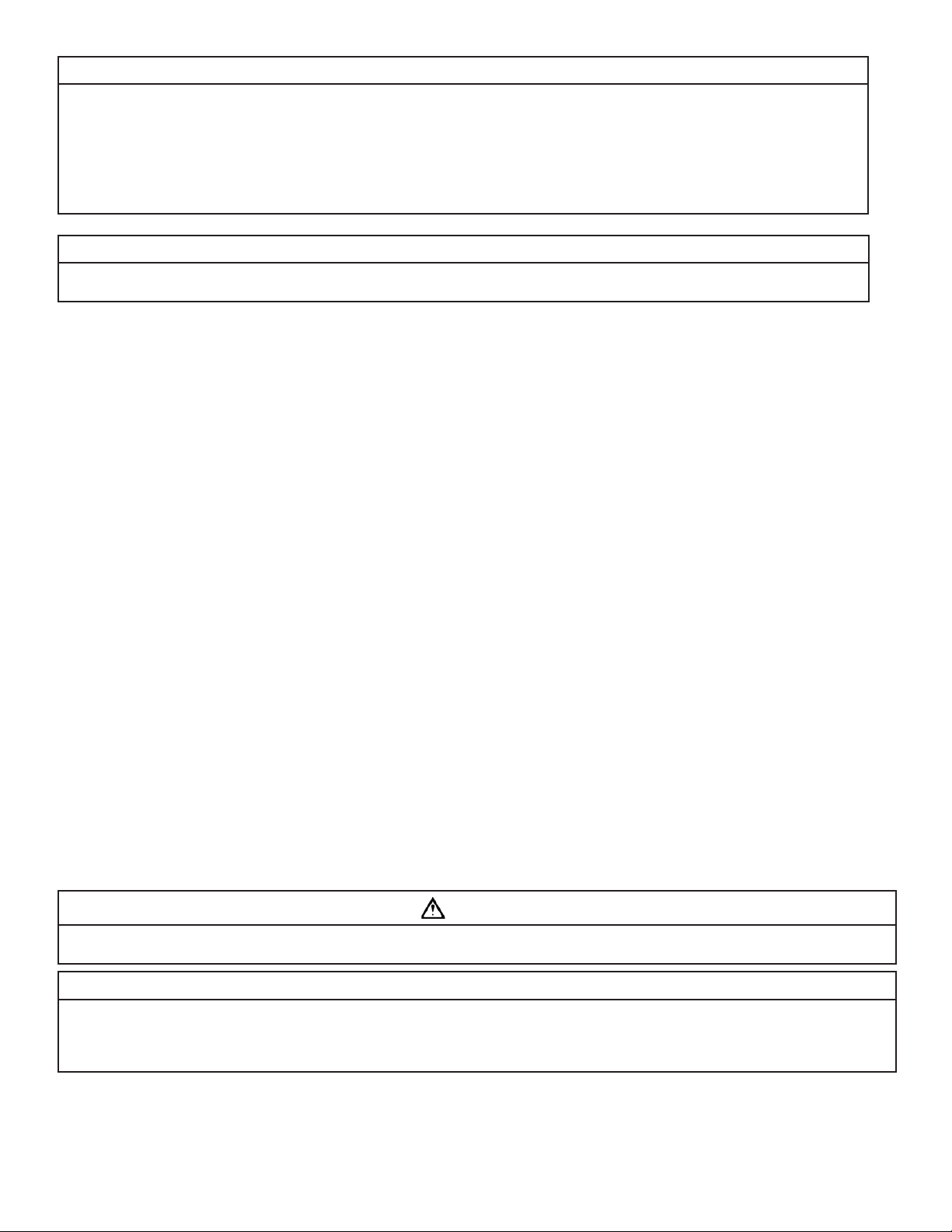
SECTION 3: INSTALLATION
Proper installation sequence of water conditioning equipment is very important. Refer to the following diagram for your particular water supply.
110/115V
SOFT WATER
RECEPTACLE
FLOW SWITCH
BRINE
TANK
TREATED WATER
WASTE DRAIN
SOFTENER SX SERIES
WASTE DRAIN
FILTER
TEST VALVE
TO WELL PUMP
CONTROLLER
FEED PUMP
PRESSURE
TANK
WASTE DRAIN
SOLUTION
PRESSURE
TRANSDUCER
TANK
VARIABLE SPEED / CONSTANT PRESSURE PUMP INSTALL
TO MAGNETIC START
FOR WELL PUMP
FROM FLOAT SWITCH
PRESSURE
CHECK VALVE
INJECTOR
ASSEMBLY
RE-PUMP
TO
SWITCH
WELL
WATER
OPTIONAL
H
S
2
AERATOR
SYSTEM
CHECK VALVE
UNTREATED WATER
FOR SPRINKLERS
OR OTHER HIGH DEMAND
INCOMING
WELL
WATER
UNTREATED WATER
FOR SPRINKLERS
OR OTHER HIGH DEMAND
CHECK VALVE
PRESSURE
TANK
CHECK VALVE
PRIMARY PRESSURE SWITCH
SOFT WATER
110/115V
RECEPTACLE
FLOW SWITCH
BRINE
TANK
TREATED WATER
WASTE DRAIN
SOFTENER SX SERIES
WASTE DRAIN
FILTER
TEST VALVE
WASTE DRAIN
AERATION
TANK
TO WELL PUMP
CONTROLLER
PRESSURE
TRANSDUCER
SOLUTION
TANK
FEED PUMP
INJECTOR
ASSEMBLY
SPLIT-STREAM INSTALLATION
Figure 1
CAUTION
To reduce the risk associated with property damage due to plugged water lines:
• Pay particular attention to correct orientation of control valve. Water fl ow should match arrow on control valve. The Inlet and Outlet of other water
treatment equipment products will vary depending on the control valve brand used.
INCOMING
WELL
WATER
3-1
Page 9
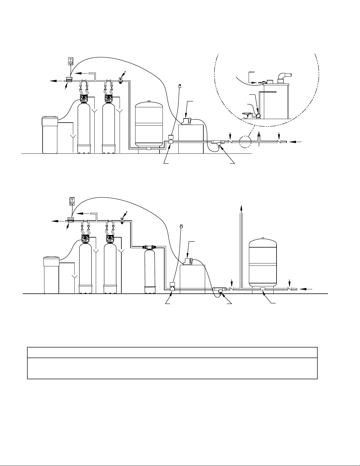
Step 1
CAUTION
CAUTION
To reduce the risk associated with skin, eye, and respiratory tract irritation from gravel
and fi lter media during installation:
• Gravel and several types of fi lter media may be used in this product, depending upon the
application. During installation, dust may cause irritation to skin, eyes, and respiratory tract.
• Utilize a NIOSH-approved dust fi lter mask, protective gloves, and appropriate eye protection
when handling and pouring gravel and fi lter media.
• To request an MSDS relating to the media included with this product, call 203-238-8965 or go
to www.3M.com, select country, and use the search engine to search MSDS. For emergencies, call 800-364-3577 or 651-737-6501 (24 hours).
a) Remove the control valve by rotating the valve head assembly to the left or counter-clock-
wise and set aside to reassemble after media is loaded into the tank. Before loading the
MEDIA into the tank, the distributor tube must be all the way to the bottom of the tank. IThe
distributor should be removed and the gravel dumped out and saved. The distributor should
then be replaced in the empty tank making sure it rests on the bottom. Use the centeringtool
provided to hold the riser tube (not shown) in the center and prevent media from entering
the distributor tube. Material lodged in the distributor tube can enter the control valve, thus
damaging it. First pour the gravel removed earlier back into the media tank, followed by the media. Using a water hose or clean pail fi ll the media tank
with water to just short of the threads on media tank.
b) Lubricate the o-ring on the adapter base with silicone grease. Reinstall the control valve making sure the riser tube fi ts into the valve body tube adaptor
protruding from the bottom of valve body, being careful not to pinch the o-ring.
c) Locate the bypass valve assembly and connection fi ttings shipped with the sulfur reduction unit. Assemble the connection fi ttings and attach to the bypass
valve as shown in Figure 3.
Figure 2. FILLING MEDIA TANK
Step 2
Shut off all water at main supply valve. On a private well system, turn off power to the pump and drain the pressure tank. Make certain pressure is relieved
from the complete system by opening the faucet closest to the system.
CAUTION
To reduce the risk associated with property damage due to water leakage:
• SHUT OFF FUEL OR ELECTRIC POWER SUPPLY TO WATER HEATER after water is shut off.
Step 3
The feed pump and solution tank require assembly prior to use (Figure 4).
a) Unpackage feed pump.
b) Install injection assembly in water supply line prior to pressure tank and pressure switch. Note: The position of the installation position and direction of
the injection assembly as shown in Figure 4.
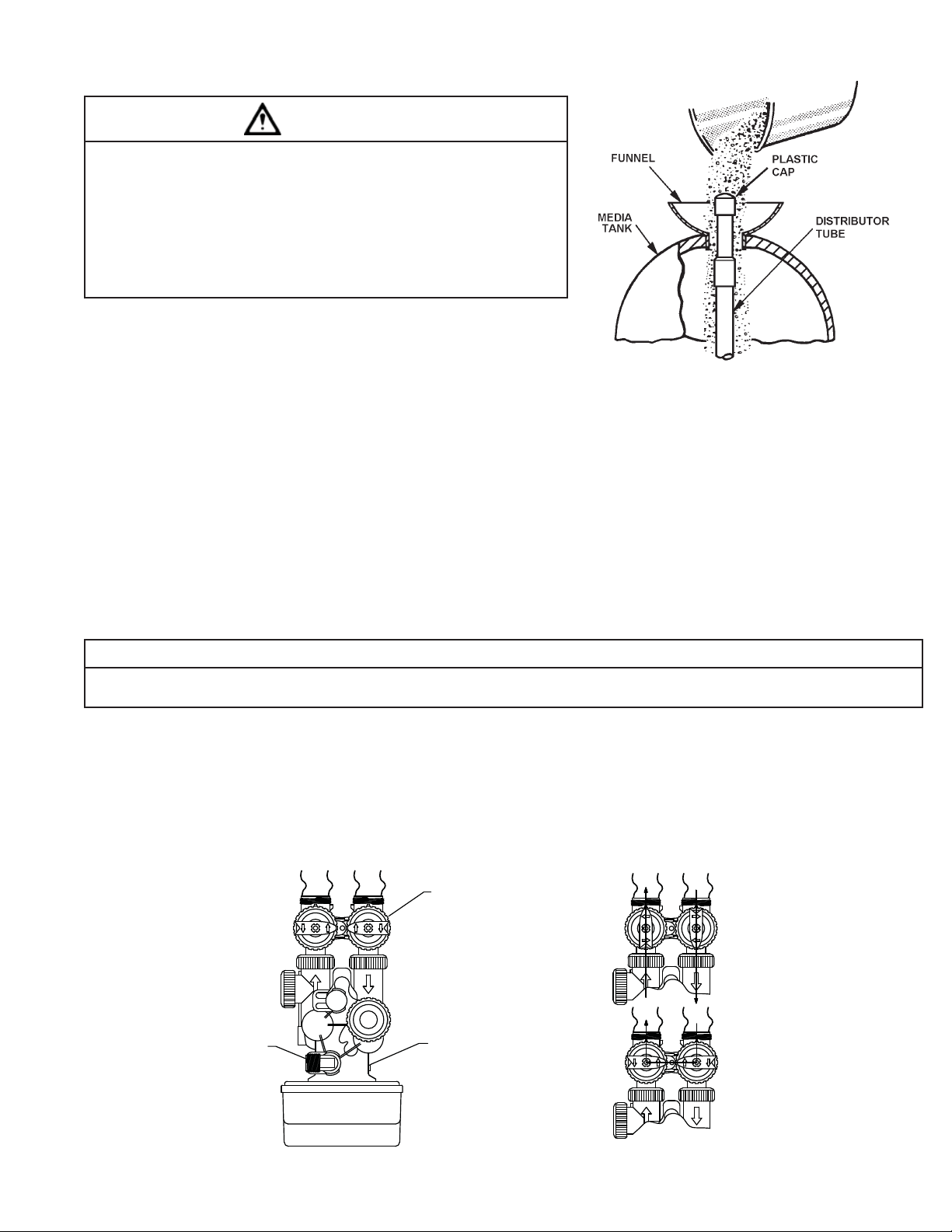
INOUT
OFF
OFF
OFF
OFF
BYPASS VALVE
Treated
Water Exits
Supply Water
OFF
OFF
OFF
Enters
OFF
NORMAL OPERATION
DRAIN LINE FLOW
CONTROL ASSEMBLY
CONTROL
VALVE BODY
Supply (Untreated)
Water Exits
Figure 3. FILTER ASSEMBLY TOP VIEW
3-2
Supply Water
OFF
OFF
OFF
Enters
OFF
BYPASS OPERATION
Page 10

c) Attach bleed valve to top of feed pump head. The white nut on discharge (top) of feed pump must be removed. The bleed valve can now be attached,
make sure to use o-ring provided.
d) Lower the precut suction line tubing assembly (clear tube with foot valve assembly and ceramic weight) into the opening of the solution tank. Feed the
tubing into the proper hole in the top of the solution tank. The foot valve assembly when properly placed should be about 1” to 1.5” off the bottom of the
solution tank.
e) Mount the feeder pump to the top of the solution tank. Before securing the feeder pump to the solution tank, remove the compression nut from the check
valve assembly and slide over suction tubing to determine the approximate length of the tubing. Trim as necessary. Secure tubing to check valve assembly
by tightening the fi tting using your hands only.
f) Attach bleed return line (short white tubing) to connection on side of bleed valve and feed down into solution tank through pre-drilled hole.
g) Attach discharge line (remaining long white tubing) to connection on top of bleed valve. Cut and attach this line to the Injection Assembly installed in Step 3b.
h) The installation of the feed pump requires a means to disconnect the feed pump from the power supply should service or maintenance to the feed pump
be required. While not required, it is suggested that the voltage of the feed pump match the voltage of the water pump. The feed pump that is shipped
with the standard unit is rated for 120 volt while most well pumps are rated for 240 volts.
Figure 4. FEEDER SYSTEM SCHEMATIC
IMPORTANT NOTE
Electric feed pump must be connected to the same voltage as the well pump or power supply. (Do not cut feed pump power cord.)
Step 4
Cut main supply line as required to fi t plumbing to inlet and outlet of bypass valve.
Step 5
Attach plumbing. DO NOT apply heat to any fi ttings connected to bypass or control valve, as damage may result to internal parts or connecting adapters. Make
certain water fl ow enters through inlet and discharges through outlet.
3-3
Page 11

CAUTION
CAUTION
To reduce the risk associated with property damage due to water leakage:
• Do not use a torch or other high temperature sources near fi lter system, cartridges, plastic fi ttings or plastic plumbing.
• On plastic fi ttings, never use pipe sealant or pipe dope. Use PTFE thread tape only, pipe dope properties may deteriorate plastic.
• Take care when using pliers or pipe wrenches to tighten plastic fi ttings, as damage may occur if over tightening occurs.
IMPORTANT NOTE
If installation is to be a split stream prior to media tank (Figure 1) refer to Special Service Instructions following STEP 14.
Step 6
Attach drain line to drain line fi tting. To prevent back pressure from reducing fl ow rate below minimum required for backwash, the drain line MUST BE sized according to run length and relative height. Be careful not
to bend fl exible drain tubing sharply enough to cause “kinking” (if kinking occurs drain line MUST BE replaced).
Typical examples of proper drain line diameters are:
1) 1/2” ID up to 15 ft. when discharge is lower than inlet.
2) 5/8” ID up to 15 ft. when discharge is slightly higher than the inlet.
3) 3/4” ID when drain is 25 ft. away and/or drain is installed overhead.
Some areas prohibit the use of fl exible drain lines. Check your local pluming code prior to installation.
Step 7
Position drain line over drain and secure fi rmly. To prevent back-siphoning of sewer water, provide an air-gap
of at least 2 in. or 2 pipe diameters between end of drain hose and drain (Figure 5). Do not raise drain line
more than 10 ft. above fl oor.
Figure 5. DRAIN
Step 8
CAUTION
To reduce the risk associated with skin, eye, and respiratory tract irritation from water treatment chemicals:
• Several types of water treatment chemicals may be used in this product, depending upon the application. During installation and use, exposure may cause irritation to
skin, eyes, and respiratory tract.
• Utilize a NIOSH-approved dust fi lter mask, protective gloves, and appropriate eye protection when handling and pouring water treatment chemicals.
• To request an MSDS relating to the media included with this product, call 203-238-8965 or go to www.3M.com, select country, and use the search engine to search
MSDS. For emergencies, call 800-364-3577 or 651-737-6501 (24 hours).
Pour two (2) gallons of sulfur reduction media into the solution tank. Under most operating conditions sulfur reduction media should be diluted with an equal amount
of sulfur-free (preferably soft) water. In some situations, however, where a high sulfur concentration and/or a high pumping rate exists, the sulfur reduction media
must be used in undiluted form in order to provide a high enough feed rate to precipitate all the sulfur. To determine if the sulfur reduction media should be diluted
or undiluted, multiply the pumping rate of your well pump by the Hydrogen sulfi de gas (H
Pumping Rate ______ x Hydrogen Sulfi de (H2S) ______ = __________
(gpm) (ppm) (Number)
* Refer to CHECK YOUR WATER PRESSURE PUMP RATE, Section 2 for proper method of determining pumping rate.
If the resulting number is less than 90, dilute the sulfur reduction media with an equal amount of water. If the number is 90 or above, do not dilute the sulfur reduction media. (EXAMPLE: 8 gpm pumping rate x 8 ppm sulfur = 64. 64 is less than 90 - therefore, dilute the sulfur reduction media with an equal amount of water
free of hydrogen sulfi de gas. This is the starting point for setting the correct feed rate).
S) concentration as determined by your water analysis (Page 2-1):
2
Step 9
Normally the feed pump operates only when the well pump runs; however, to facilitate calibrating the feed pump, remove the feed pump power cord from the special
receptacle controlled by the pressure switch and plug it into any 110/115V power sourc. To prime pump, turn knob on bleed valve to “BLEED” position and allow
pump to run until solution appears in bleed return line. Turn knob on bleed valve to “PUMP” position and continue running feed pump until discharge tube fi lls to
injection assembly, then plug feed pump power cord into special receptacle controlled by the pressure switch.
3-4
Page 12

IMPORTANT NOTE
If an air bubble appears in the discharge line of the feed pump, remove the discharge line at the injection point, hold the tube vertical to allow air bubble
to be discharged and replaced with sulfur reduction media. Unplug the feed pump, place fi nger over the end of the feed line, replace tubing to the injection
point quickly. taking care to minimize any fl uid loss during reconnection. Plug feed pump back into receptacle.
Step 10
Set feed pump stroke length to 50%. Make certain that fi lter bypass valve is in bypass position (Figure 3). Turn on power to well pump. Allow water system to repressurize. After system has pressurized check for leaks in plumbing.
Step 11
Open a cold water faucet, so that well pump continues to run at 1/2 pressure; i.e., 30 psi if system operates at 20/40 psi. Draw sample of water from test cock.
Adjust feed pump rate just enough to eliminate sulfur odor in water coming from test cock. (Dark brown color of sample water is normal and is caused by precipitated
sulfur and will be reduced by the sulfur reduction system). Refer to Section 4 on dilution procedures to fi ne tune sulfur reduction media feed rate and concentration
(dilution) for most effi cient and economical setting. Close cold water faucet.
IMPORTANT NOTE
Should a sulfur odor persist even when the dial setting is at its maximum, reread STEP 8. Also, check to determine if the odor is in the hot water only, and,
if it is, the hot water heater may need to be drained and cleaned.
Step 12
a) Make certain the bypass valve inlet and outlet knobs are in “bypass” position. After all plumbing connections have been completed, open main water
shut-off valve and restore power to well pump. Check for leaks and correct as necessary.
b) Plug the control valve power cord into 110v/60Hz, non-switched power source. Program the control valve (refer to page 3-1).
NOTE: Backwashing settings for the control valve are factory preset. The control valve design permits adjustment of the salt setting. This adjustment
may be necessary when unusual operating conditions exist, such as high concentrations of iron, manganese or hardness and/or high fl ow rates or daily
water consumption.
c) Manually set the control to backwash position. Press and hold the REGEN button for 3 seconds. The valve will advance to the backwash position. Unplug
power cord to prevent the unit from advancing automatically.
d) Partially open the inlet knob on bypass valve (Figure 3). This will allow the unit to fi ll slowly from the bottom up, reducing air entrapment. Allow the unit
to fi ll slowly, failure to do so could result in loss of resin to the drain. Once a steady stream of water, with no air sputtering, is fl owing to the drain, the
inlet and outlet bypass knobs can be fully opened (refer to Figure 3).
e) Plug the power cord back into the power source. Press the REGEN button and wait for the valve to advance to the next backwashing position. Repeat the
process until the valve is in the Service Position (Time of Day will be on the display).
f) Test for residual copper, the fi nal amount of copper that should be present in the fi lter water supply is < 0.5 ppm.
Step 13
Set the TIME-OF-DAY (see HOW TO SET TIME OF DAY). The backwashing frequency is factory preset for every other day. This frequency need not be adjusted unless the sulfur reduction is great enough to require daily backwashing. Refer to HOW TO CHANGE THE BACKWASHING PROGRAM SETTINGS if change is required.
NOTE: Should you experience a water system pressure loss or bleed-through of the precipitant prior to a scheduled backwash, put the system into a manual backwash and increase the frequency of backwashing.
IMPORTANT INSTRUCTIONS: If water is supplied by a public or community source, or water line is split-streamed anywhere ahead of the media tank (See Figure 1):
SPECIAL SERVICE INSTRUCTIONS:
Under normal circumstances removal of the valve should not be required. However, if it must be removed, disconnect the plumbing attached to the bypass valve
fi rst. Then, rotate the valve head assembly to the left or counter-clockwise. Before attempting any disassembly, pressure should be relieved by shutting off water to
the system and opening a faucet. Upon reassembly, all o-rings should be lubricated with silicone grease. Reattach valve head assembly by rotating to the right or
clockwise until valve head assembly is seated to the tank hand tight. Reconnect the plumbing to the bypass valve.
3-5
Page 13

SECTION 4: FINE TUNING THE CSX SULFUR REDUCTION SYSTEM
IMPORTANT NOTES
CAUTION
In order to make the installation and operation of your sulfur reduction system the most economical, a brief discussion of the concept of dilution must be undertaken. Dilution is defi ned as the reduction of concentration of a particular constituent by the addition of another. In the case of sulfur reduction media, the dilution
is performed with the addition of treated water. The idea of dilution rate and ratio may be best demonstrated by several examples.
EXAMPLE 1
CAUTION
Initial concentration: 1 Gallon of sulfur reduction media
If we add: 1 Gallon of water
Total solution: 2 Gallons of mixture
In the fi nal 2 gallons of mixture, 1/2 (1 gallon out of 2 gallons) is sulfur reduction
media. This can be stated two different ways. First, the dilution ratio is 1:1 (1
gallon sulfur reduction media/1 gallon water) or secondly, by saying a 50% dilution was performed (1/2, i.e. 50%, of the fi nal mixture is sulfur reduction media).
EXAMPLE 2
Initial concentration: 1 Gallon of sulfur reduction media
If we add: 3 Gallons of water
Total Solution: 4 Gallons of mixture
In this example, we end up with 1 gallon of sulfur reduction media in 4 gallons of mixture, therefore 1/4 or 25% of the fi nal mixture is sulfur reduction media.
Again this can be stated two different ways, fi rst, the dilution ratio is 1:3 (1 gallon /3 gallons water) and secondly by saying a 25% dilution was performed (1/4,
i.e. 25%, of the fi nal mixture is sulfur reduction media).
To reduce the risk associated with skin, eye, and respiratory tract irrita-
tion from water treatment chemicals:
• Several types of water treatment chemicals may be used in this product,
depending upon the application. During installation and use, exposure may
cause irritation to skin, eyes, and respiratory tract.
• Utilize a NIOSH-approved dust fi lter mask, protective gloves, and appropriate eye protection when handling and pouring water treatment chemicals.
• To request an MSDS relating to the media included with this product, call
203-238-8965 or go to www.3M.com, select country, and use the search
engine to search MSDS. For emergencies, call 800-364-3577 or 651-7376501 (24 hours).
EXAMPLE 3
Suppose we have performed a 1:1 (50%) dilution by mixing 1 gallon of sulfur reduction media with 1 gallon of water. We now have a total of 2 gallons of mixture.
After performing the dilution, we decide the mixture is not concentrated enough, so we add 1 gallon of sulfur reduction media to the 2 gallon mixture. The ratio
of sulfur reduction media to water is now 2:1 (2 gallons of sulfur reduction media/1 gallon of water) and the total amount of mixture is now 3 gallons. The sulfur
reduction media is now diluted 2/3, 66.7% (2 gallons sulfur reduction media/3 gallons mixture).
IMPORTANT NOTES
A ratio relates the different components of a mixture, when they all have the same units of measure, i.e. gallons of sulfur reduction media to gallons of water,
ounces of sulfur reduction media to ounces of water, pounds of sulfur reduction media to pounds of water, etc. In the examples above the ratios were expressed as 1:1, 1:3 and 2:1.
A dilution rate relates one component to the total mixture.
The fi nal amounts of sulfur reduction media and water mixed together in your installation should be recorded below.
Mixture Ratio
____ gallons sulfur reduction media _____1.0____
____ gallons water ____________
These two numbers can be used to determine the mixture ratio. By dividing the gallons of water by the gallons of sulfur reduction mediaan easy to remember
ratio can be found (see following example).
EXAMPLE 4
Suppose a fi nal mixture contains 2 gallons of sulfur reduction media and 4 gallons of water:
Ratio = 2:4 then Mixture Ratio = 2/2:4/2 = 1.0:2.0
Suppose we now wish to make up 12 gallons of solution, we would mix 4 gallons of sulfur reduction media with 8 gallons of water. This mixture contains 1 gallon
of sulfur reduction media for every 2 gallons of water, therefore our ratio of 1:2 is maintained.
Any amount of solution can be mixed using the following formulas.
Desired Gallons of Solution
Mixture Ratio of sulfur reduction media+ Mixture Ratio of Water = Gallons of sulfur reduction media Required
Desired gallons of solution - gallons of sulfur reduction media= gallons of water
Using the above example:
4-1
Page 14

Desired gallons of solution = 12
Mixture ratio of sulfur reduction media = 1.0
Mixture ratio of water = 2.0
12 12
1.0 + 2.0 = 3.0 = 4 gallons of sulfur reduction media required
12 - 4 = 8 gallons of water required
EXAMPLE 5
Desired gallons of solution = 10
Mixture ratio of sulfur reduction media= 1.0
MIXTURE RATIO OF WATER = 2.0
10 10
1.0 + 2.0 = 3.0 = 3.33 gallons of sulfur reduction media required
10 - 3.33 = 6.67 gallons of water required
EXAMPLE 6
A ratio of 1:1 exists and we have 1 gallon of sulfur reduction media and 1 gallon of water for a total of 2 gallons of mixture, the dilution rate of sulfur reduction
media is 1/2 or 50%, since there is 1 gallon of sulfur reduction media in 2 gallons of mixture.
A ratio of 1:3 gives 4 gallons of mixture, so the dilution rate of sulfur reduction media is 1/4 or 25%.
A ratio of 2:1 gives 3 gallons of mixture, so the dilution rate of sulfur reduction media is 2/3 or 66.7%.
It should be noted that the dilution is stated as: 1 gallon of sulfur reduction media is diluted with 1 gallon of water (1:1 ratio), 1 gallon of sulfur reduction media
is diluted with 3 gallons of water (1:3 ratio) or 2 gallons of sulfur reduction media is diluted with 1 gallon of water (2:1 ratio). It would be just as correct to
state: 3 gallons of water is diluted with 1 gallon of , but the ratio should now be changed from 1:3 to 3:1. The dilution rate can be stated for any component in
a mixture, but care should be taken when it is referred to in the ratio form.
Now that we have discussed the ideas of dilution rate and ratio, we can discuss the fi ne-tuning of the system to the most economical operating condition.
The basic, underlying idea of the fi ne-tuning process is to have the highest feed pump stroke frequency at the highest dilution rate of the solution. The decision whether or not to dilute can be based roughly on the stroke frequency percentage at the point where the sulfur odor disappears. If the percentage is
50% or less, the solution can be diluted 50%. After the dilution, the feed pump should once again be adjusted to the point where the smell disappears. This
adjustment process should be repeated until the feed rate exceeds 75%. There is no need to adjust the feed pump to a precise setting each time. Since the
hydrogen sulfi de gas concentration will vary from day-to-day, the best, most precise setting today may not be tomorrow. The feed pump should be adjusted
until it is set above 75%.
If upon initial installation you fi nd the feed rate is above 75% and you are feeding undiluted sulfur reduction media, it may be more economical to include an
aerator in the treatment system. An aerator will reduce the sulfur concentration 50 - 75%, depending on its effi ciency and could reduce the cost of operation
for the system substantially.
Although we have discussed the concepts of dilution in specifi c relation to the system, the same ideas hold true in other instances where dilutions may be
necessary. These situations could include chlorination, soda ash addition for pH adjustment or even when conducting tests on water samples.
4-2
Page 15

USER DISPLAYS
HOW TO CHANGE THE BACKWASHING PROGRAM SETTINGS
Step 1) Begin in normal mode and press SET + ▲ for three seconds simultaneously.
Step 2) Set the hours for backwashing using ▲ or ▼. Press SET and proceed to step 3.
Step 3) Set the minutes for backwashing using ▲ or ▼. Press SET and proceed to step 4.
Step 4) Set the days for backwashing between 1 and 99. Press SET to exit Installer Displays and Settings.
GENERAL OPERATION
When operating, the system will either display the current time of day or the days remaining until the next backwashing. Use ▲ or ▼ to toggle between the
two displays. If the remaining days is at 1, the system will regenerate at the preset time.
An arrow will appear pointing to REGEN when the system calls for backwashing.
BACKWASHING MODE
When the system is regenerating, untreated water will be used. Therefore, systems are typically set to regenerate during times of low water usage—such as
when the household is asleep.
During backwashing, the arrow will point to REGEN and the display will change to Backwashing Cycle Display, indicating the time remaining. The system
automatically runs through the steps of backwashing; upon completion, treated water is ready for use.
HOW TO MANUALLY INITIATE BACKWASHING
If a system needs to be regenerated before the next scheduled time, manual backwashing can be initiated. This may be necessary during times of heavy water
usage, including house guests or heavy laundry days.
To initiate a manual backwashing at the preset delay time, press ▲ and ▼ simultaneously. Release. An arrow will point to REGEN if backwashing is expected
“tonight.” To cancel, press ▲ and ▼ simultaneously. Release.
To initiate an immediate manual backwashing, press ▲ and ▼ simultaneously for three seconds. This request cannot be cancelled. (If a softener brine tank
does not contain salt, add salt and wait at lease two hours before initiating backwashing.
HOW TO SET TIME OF DAY
STEP 1
Step 1) Press SET
Step 2) Use ▲ and ▼ to adjust the current time hour. Time display will be 12 hour with PM indicator with
60 Hz line frequency detection on power-up. Time display will be 24 hour without the PM indicator with 50 Hz line frequency on power-up. Press SET and proceed to step 3.
SET
STEP 2
Regen
Min. Fill
Regen
Time
Time
PM
Days To
Regen
SET
Step 3) Use ▲ and ▼ to adjust the current time minutes. Press SET to exit Set Time of Day.
STEP 3
Power Loss
If power is lost for more than 8 hours, the current time of day will need to be reset. If the system is in the
middle of backwashing upon power loss, the control will continue backwashing at the point of interruption
when power is restored.
Regen
Min. Fill
Regen
Time
SET
Time
PM
Days To
Regen
Error Message
Contact the OEM for assistance if the display shows “E1,” “E2,” “E3” or “E4.” These messages are indications
the valve did not function properly.
4-3
Regen
Min. Fill
Regen
Time
SET
Time
PM
Days To
Regen
Page 16

Problem Cause Solution
1. Correct time of day not shown.
2. Error followed by a code number.
Error Code E1 — Unable to recognize start of
backwashing.
Error Code E2 — Unexpected stall
Error Code E3 — Motor ran too long. Timed
out trying to reach next cycle position
If other codes appear, contact factory.
3. Excessive pressure drop through fi lter
system.
4. Inadequate hydrogen sulfi de gas reduction
5. Regenerates at wrong time of day.
6. Water runs to drain in the service position.
7. Discoloration in treated water.
8. Taste in treated water.
9. Media in aerators at the faucets.
10. Water leaking from media tank.
SECTION 5: TROUBLESHOOTING
A. Transformer is unplugged. 1. Reconnect transformer.
B. No power at outlet. 1. Repair or use working outlet.
C. Damaged transformer. 1. Replace transformer.
D. Damaged PC board. 1. Replace PC board.
E. Outlet on a switched circuit. 1. Use a non-switched circuit.
R. Power outage. 1. Reset time of day.
G. Damaged PC board. 1. Replace PC board.
H. Time of day set wrong. 1. Reset to the correct time.
A. Valve just serviced.
B. Foreign material stuck in valve. 1. Check piston and spacer stack for obstruction.
C. Excessive piston resistance. 1. Replace piston and spacer assembly.
D. Position not in the home position.
A. Filter system not backwashing. 1. Drive motor not operative.
B. Inadequate pumping rate. 1. Verify pumping rate meets or exceeds minimum pumping for model
C. Drain line inadequate. 1. Drain line too long or too high or too small of diameter, refers to
A. Hydrogen sulfi de gas greater than 15 ppm. 1. Install a H2S Aerator ahead of existing CSX unit.
B. Low solution feed. 1. Increase solution feed rate.
C. Feed Pump not operating. 1. Feed pump not plugged into power supply.
A. Wrong time of day displayed. 1. Reset the time of day.
B. Past power outage. 1. Reset the time of day.
C. Time of backwashing set wrong. 2. Reset the time of backwashing.
A. Wrong time of the day displayed. 1. Correct time of day.
B. Past power outage. 1. Correct time of day.
C. Time of backwashing set wrong. 1. Correct time of backwashing.
A. Insuffi cient reduction of hydrogen sulfi de gas prior to
fi lter unit.
B. Too high of solution feed . 1. Retest hydrogen Sulfi de gas in incoming water and reduce concen-
C. Inadequate pump rate 1. Recheck pumping rate to verify minimum gpm.
D. Drain line issue 1. Verify the drain line meets the minimum requirements listed on page
A. Sulfur in feed water. 1. Treat with the appropriate treatment product. Contact technical
B. Organics in treated water. 1. Treat with the appropriate treatment product. Contact technical
A. Unit installed backwards. 1. Ensure that the piping enters to inlet side of bypass and exits on
B Distributor is damaged. 1. Remove distributor tube from media tank and inspect. Replace as
C. Media was loaded in distributor tube while loading
fi lter unit.
A. Media tank was subjected to a vacuum condition. 1. Replace media tank and check to see that either a check valve or
B. Media tank has been damaged. 1. Contact installing contractor to have evaluated and replaced.
C. Pin hole in media tank. 1. Contact installing contractor to have evaluated and replaced.
2. Check circuit breaker in main power box.
1. Press SET HOUR and
source from PC board.
1. Press SET HOUR and
PC board.
2. Drain line is kinked, blocked or frozen.
3. Drain line fl ow control in blocked with debris, scale or gravel.
being used.
manual for minimum requirements.
2. Increase solution concentration.
2. Fuse on circuit board of feed pump needs to be replaceg.
3. Circuit board on feed pump damaged.
1. Increase the rate of solution feed
2. Increase the concentration of solution
tration of solution or reduce feed rate.
3-4 of this manual.
services for equipment recommendations.
services for equipment recommendations.
the outlet side. (Refer to red handles on bypass to check for fl ow
direction.)
needed.
1. Remove distributor tube from media tank, clean and reinstall correctly. Cover distributor tube with plug included.
back fl ow prevention device is installed and operating.
for 3 seconds or momentarily unplug power
or momentarily unplug power source from
5-1
Page 17

11. Time of day fl ashes on and off.
12. Valve stalled in backwashing.
13. Valve does not regenerate automatically
when the
and buttons are pushed.
14. Valve does not regenerate automatically,
but does when
and are depressed.
A. Power has been off for more than eight (8) hours. 1. Reset the time of day.
B. SET HOUR was pressed. 1. Reset the time of day.
A. Motor not operating. 1. Replace motor.
B. No power at the outlet 1. Repair outlet or use a working one.
2. Check circuit breaker at the main power box.
C. Damaged transformer. 1. Replace transformer.
D. Damaged PC board. 1. Replace PC board.
E. Broken drive gear or drive cap assembly. 1. Replace gear or drive cap assembly.
F. Broken piston retainer. 1. Replace main piston assembly.
G. Broken main piston. 1. Replace main piston assembly.
A. Transformer unplugged. 1. Connect transformer and the PC board power
B. No power at outlet. 1. Restore or repair power source.
C. Broken drive gear or drive cap assembly. 1. Replace gear or drive cap assembly.
D. Damaged PC board. 1. Replace PC board.
A. Programming error. 1. Review programming of control valve.
B. Damaged PC board. 1. Replace PC board.
5-2
Page 18

SECTION 6: SPECIFICATIONS AND OPERATING DATA
ITEM CSX100 CSX200
Nominal Media Volume, cu. ft. (cu. mtr.) 1.0 (0.03) 2.0 (0.06)
Gravel Underbed, lbs (kg) 13 (5.9) 18 (8.2)
Operating Flow Rate, gpm (lpm) (Note 1)
Service (intermittent)
Peak (10 minutes max. duration)
Pressure Loss @ Flow Rates, psi (kPa)
Service
Peak
Backwash Rate, (Note 2), gpm (lpm) 5.3 (20.1) 7.5 (28.4)
Service Pipe Size, inches (cm) 1 (2.5) 1 (2.5)
Tank Diameter x Height, inches (cm)
Minimum Space Required
Width, inches (cm)
Depth, inches (cm)
Height, inches (cm)
Approximate Shipping Weight, lbs (kg) 163 (73.9) 271 (122.9)
Maximum operating temperatures 110°F (43.3°C); Electrical requirements 110 Volt (60 Hz); Operating pressure 20-125 psi (138-862 kPa).
6.0 (22.7)
10.0 (45.5)
5 (0.034)
13 (0.89)
10 x 44
(25.4 x 112)
10 (25.4)
16 (40.6)
53 (134.6)
9.0 (34.1)
13.0 (59.1)
8 (0.055)
14 (0.097)
12 x 54
(30.5 x 138)
12 (30.4)
16 (40.6)
63 (160)
Notes:
(1) For satisfactory performance, indicated durations should not be exceeded; Flow rates specifi ed are adequate for normal residential applications. This
fi lter system is not intended to treat commercial applications.
(2) Indicated pressure loss is for new systems, these losses will increase as the fi lter is used and the longer the duration since last backwashing.
6-1
Page 19

SECTION 7: COMPONENT LISTS
REF
DESCRIPTION CSX100 CSX200
NO.
1 Control Valve, Complete, Less Bypass Valve W217530-003-00Z W217750-003-00Z
1a O-ring Included with Item #3 V3180 V3180
2 Bypass Valve V3006 V3006
3 Media Tank w/Base 6236001-1044 6236001-1054
4 Distributor Tube C37S-16-44 C37S-16-54
5 Media SX-050P (2) SX-050P (4)
6 Gravel Underbed 1/4” x 1/8” QC-12P QC-15P
Note: When ordering replacement or repair components be sure to always specify by the unit or model number to ensure the correct parts are ordered.
OFF
OFF
OFF
OFF
1
Items Not Shown
Description of Item Part Number
Wrench V3193- 01
Funnel U1006
1” Plumbing Connection Fitting
Straight Male NPT Fitting
Straight Brass Sweat Fitting
Adapter Kit - 1” NPT
- 1” Sweat Fittings
V3007-04
V3007-02
V3007-02*
V3007-04*
Cover V3175-WCA
Feed Pump LA30P
15 gal. Solution Tank ST15Z
Injection Assembly TBF1Z
Feed Pump with Injection Assembly
LA30P-S15T-TBF
and 15 gal. Solution Tank
3
1a
4
2
*See assemblies drawing for individual components
5
7-1
Page 20

FILTER DRIVE CAP ASSEMBLY, DOWNFLOW PISTON,
4a
AND SPACE STACK ASSEMBLY
Reference No. Part No. Description Quantity
1 V3005 Spacer Stack Assembly 1
2 V3004 Drive Cap Assembly 1
3 V3178 Drive Back Plate 1
4 V3001 Piston Downfl ow Assembly 1
6 V3135 O-ring 228 1
7 V3180 O-ring 337 1
8 V3105 O-ring 215 Pilot Tube 1
NOT SHOWN V3001 Downfl ow body Assembly 1
3
1
2
4b
4
7
8
6
7-2
Page 21

Front Cover and Drive Assembly
Reference No. Part No. Description Quantity
1 V3175TC-01 Time Clock Front Cover Assembly 1
2 V3107-01 Motor 1
3 V3106-01 Drive Bracket & Spring Clip 1
4 V3818TC Time Clock PC Board 1
5 V3110 Drive Gear 12 x 36 1
6 V3109 Time Clock Cover 1
NOT SHOWN V3002TC Time Clock Drive Assembly 1
NOT SHOWN V3186 AC Adapter 110V - 12V 1
NOT SHOWN V3175-WCA Cover 1
Drawing number parts 2 through 6 may be purchased as a complete assembly, part V3202.
1
4
6
5
3
2
7-3
Page 22

Quick Connect Bypass Valve
Reference No. Part No. Description Quantity
1 V3151 Nut 1” Quick Connect 2
2 V3150 Split Ring 2
3 V3105 O-ring 2
1
2
3
1
2
3
7-4
Page 23

Installation Fitting Assemblies
Quick Connect Assemblies
Part # V3007-02
Reference No. Part No. Description Quantity
1 V3151 1” Quick Connect Nut 2
2 V3150 1” Quick Connect Split Ring 2
3 V3105 1” Quick Connect O-Ring 215 2
4 V3188 1” Brass Sweat Assembly 2
4
3
1
2
Part # V3007-04
Description: 1” Plastic Male NPT Assembly
Reference No. Part No. Description Quantity
1 V3151 1” Quick Connect Nut 2
2 V3150 1” Quick Connect Split Ring 2
3 V3105 1” Quick Connect O-Ring 215 2
4 V3164 1” NPT Quick Connect Plastic Male Assembly 2
4
1
2
3
7-5
Page 24

Quick Connect 3/4” Drain Line Housing
Reference No. Part No. Description Quantity
1 H4615 Elbow Locking Clip 1
2 PKP10T58-BLK 5/8” Insert Sleeve
3 V3192 Quick Connect 3/4” Drain Elbow Nut 1
4 V3158-01 Quick Connect 3/4” Drain Elbow 1
5 V3163 O-ring 019 1
6 V3159-01 Drain Line Flow Control Retainer Assembly 1
7 V3162-027 2.7 gpm Drain Line Flow Control Button 1
7 V3162-032 3.2 gpm Drain Line Flow Control Button 1
7 V3162-53 5.3 gpm Drain Line Flow Control Button 1
Water
Flow
Proper DLFC orientation
directs water flow towards
the washer face with
rounded edge.
2
3
4
5
6
1
7
7-6
Page 25

Limited Warranty: 3M Purifi cation Inc. warrants this Product to be free from defects in material and workmanship during normal use for the warranty period set forth below. The
SECTION 8: LIMITED WARRANTY
warranty period commences from the date of purchase. This warranty does not cover failures resulting from abuse, misuse, alteration or damage not caused by 3M Purifi cation Inc.
or failure to follow installation and use instructions. No warranty is given as to the service life of any fi lter cartridge, membrane, or media as it will vary with local water conditions and
water consumption.
3M PURIFICATION INC. MAKES NO OTHER WARRANTIES OR CONDITIONS, EXPRESS OR IMPLIED, INCLUDING, BUT NOT LIMITED TO, ANY IMPLIED WARRANTY OR CONDITION OF MERCHANTABILITY OR FITNESS FOR A PARTICULAR PURPOSE OR ANY IMPLIED WARRANTY OR CONDITION ARISING OUT OF A COURSE OF DEALING, CUSTOMER
OR USAGE OF TRADE.
If the Product is found defective within the warranty period, your exclusive remedy and 3M Purifi cation Inc.’s sole obligation shall be, at 3M Purifi cation Inc.’s option, to replace or
repair the Product or refund the purchase price of the Product. This warranty does not cover labor. The remedy stated in this paragraph is Customer’s sole remedy and 3M Purifi ca-
tion Inc.’s exclusive obligation.
Warranty Period:
• One (1) year on the entire product unit
• Five (5) years on the media tank only (does not include internal component parts)
• Five (5) years on the control valve
• Five (5) years on salt storage container and components*
Limitation of Liability: 3M Purifi cation Inc. will not be liable for any loss or damage arising from this 3M Purifi cation Inc. product, whether direct, indirect, special, incidental, or
consequential, regardless of the legal theory asserted, including warranty, contract, negligence or strict liability. Some states and countries do not allow the exclusion or limitation of
incidental or consequential damages, so the above limitation or exclusion may not apply to you.
Warranty Claims:
To obtain warranty service, call 1-800-222-7880 or mail your request to: 3M Purifi cation Inc., 400 Research Parkway, Meriden, CT 06450. Proof of purchase (original sales receipt)
must accompany the warranty claim, along with a complete description of the Product, model number and alleged defect. This warranty gives you specifi c legal rights, and you may
have other rights which may vary from state to state, or country to country.
* Water Softeners only
8-1
Page 26

NOTES
Page 27

NOTES
Page 28

3M Purifi cation Inc.
400 Research Parkway
Meriden, CT 06450
1-800-222-7880
www.3Mpurifi cation.com
3M is a trademark of 3M Company.
Aqua-Pure is a trademark of 3M Company used under license.
© 2011 3M Company. All rights reserved.
 Loading...