

Page 1

INSTALLATION AND OPERATING
INSTRUCTIONS
APIF SERIES RESIDENTIAL
IRON AND MANGANESE REDUCTION SYSTEMS
Models
APIF100 APIF100J APIF100M APIF100PT APIF100MPT APIF100MJ
APIF100DM APIF100PTDM APIF100MDM APIF100MPTDM
APIF150 APIF150J APIF150M APIF150PT APIF150MPT APIF150MJ
APIF150DM APIF150PTDM APIF150MDM APIF150MPTDM
APIF200 APIF200J APIF200M APIF200PT APIF200MPT APIF200MJ
APIF200DM APIF200PTDM APIF200MDM APIF200MPTDM
APIF300 APIF300J APIF300M APIF300PT APIF300MPT APIF300MJ
Installer, please leave with homeowner.
Homeowner, retain for future reference.
Page 2
Read, understand, and follow all safety information contained in these instructions prior to installation and use of the APIF Series Residential Iron and Manganese
Reduction System. Retain these instructions for future reference. Failure to follow installation, operation and maintenance instructions may result in property damage
and will void warranty.
Intended use:
The APIF Series Residential Iron and Manganese Reduction Systems are intended for use in homes and have not been evaluated for other uses. These systems are intended
to be installed near the entry point of a home water line, and must be installed by qualifi ed professional installers or licensed plumbing contractors in accordance with state
and local plumbing codes and these installation instructions.
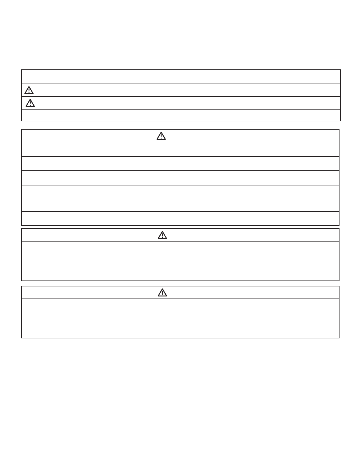
EXPLANATION OF SIGNAL WORD CONSEQUENCES
SAFETY INFORMATION
WARNING
CAUTION
CAUTION
To reduce the risk associated with choking:
• Do not allow children under 3 years of age to have access to small parts during the installation of this product.
To reduce the risk associated with ingestion of contaminants:
• Do not use with water that is microbiologically unsafe or of unknown quality without adequate disinfection before or after the system.
To reduce the risk of physical injury:
• Shut off inlet water supply and depressurize system as shown in manual prior to service.
To reduce the risk associated with a hazardous voltage:
• If the home electrical system requires use of the cold water system as an electrical safety ground, a jumper must be used to ensure a suffi cient ground connection across
the fi lter installation piping — refer installation to qualifi ed personnel.
• Do not use the system if the power cord is damaged — contact qualifi ed service personnel for repair.
To reduce the risk associated with back strain due to the heavy weight of the various system components:
• Follow safe lifting procedures.
Indicates a potentially hazardous situation, which, if not avoided, could result in death or serious injury and/or property damage.
Indicates a potentially hazardous situation, which, if not avoided, may result in minor or moderate injury and/or property damage.
Indicates a potentially hazardous situation, which, if not avoided, may result in property damage.
WARNING
CAUTION
To reduce the risk associated skin, eye, and respiratory tract irritation from gravel and fi lter media during installation:
• Gravel and several types of fi lter media may be used in this product, depending upon the application. During installation, dust may cause irritation to skin, eyes, and
respiratory tract.
• Utilize a NIOSH-approved dust fi lter mask, protective gloves, and appropriate eye protection when handling and pouring gravel and fi lter media.
• To request an MSDS relating to the media shipped with this product, call 203-238-8965 or go to www.3M.com , select country, and use the search engine to search
MSDS. For emergencies, call 800-364-3577 or 651-737-6501 (24 hours).
CAUTION
To reduce the risk associated with skin, eye, and respiratory tract irritation from water treatment chemicals:
• Several types of water treatment chemicals may be used in this product, depending upon the application. During installation and use, exposure may cause irritation
to skin, eyes, and respiratory tract.
• Utilize a NIOSH-approved dust fi lter mask, protective gloves, and appropriate eye protection when handling and pouring gravel and fi lter media.
• To request an MSDS relating to the media shipped with this product, call 203-238-8965 or go to www.3M.com , select country, and use the search engine to search
MSDS. For emergencies, call 800-364-3577 or 651-737-6501 (24 hours).
Page 3

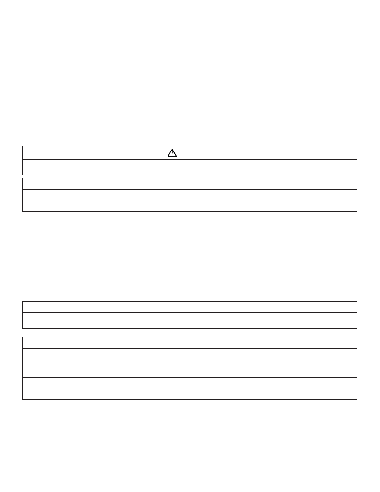
CAUTION
To reduce the risk associated with property damage due to water leakage:
• Read and follow Use instructions before installation and use of this water treatment system.
• Installation and use MUST comply with existing state or local plumbing codes.
• Protect from freezing, relieve pressure and drain system when temperatures are expected to drop below 33°F (0.6°C).
• Do not install on hot water supply lines. The maximum operating water temperature of this fi lter system is 110°F (43.3°C).
• Do not install systems in areas where ambient temperatures may go above 110° F (43.3° C).
• Do not install if water pressure exceeds 125 psi (861 kPa). If your water pressure exceeds 80 psi (552 kPa), you must install a pressure limiting valve. Contact a
plumbing professional if you are uncertain how to check your water pressure.
• Do not install where water hammer conditions may occur. If water hammer conditions exist you must install a water hammer arrester. Contact a plumbing professional if you are uncertain how to check for this condition.
• Where a backfl ow prevention device is installed on a water system, a device for controlling pressure due to thermal expansion must be installed.
• Do not use a torch or other high temperature sources near fi lter system, cartridges, plastic fi ttings or plastic plumbing.
• On plastic fi ttings, never use pipe sealant or pipe dope. Use PTFE thread tape only, pipe dope properties may deteriorate plastic.
• Take care when using pliers or pipe wrenches to tighten plastic fi ttings, as damage may occur if over tightening occurs.
• Do not install in direct sunlight or outdoors.
• Mount system in such a position as to prevent it from being struck by other items used in the area of installation.
• Ensure all tubing and fi ttings are secure and free of leaks.
• SHUT OFF FUEL OR ELECTRIC POWER SUPPLY TO WATER HEATER after water is shut off.
• Do not install system where water lines could be subjected to vacuum conditions without appropriate measures for vacuum prevention.
• Do not apply heat to any fi tting connected to bypass or control valve as damage may result to internal parts or connecting adapters.
• Install on a fl at/level surface. It is also advisable to sweep the fl oor to eliminate objects that could pierce the media tank.
To reduce the risk associated with property damage due to plugged water lines:
• Pay particular attention to correct orientation of control valve. Water fl ow should match arrow on control valve. The inlet and outlet of other water treatment
equipment products will vary depending on the control valve brand used.
• Failure to follow instructions will void warranty.
IMPORTANT NOTES
Page 4

TABLE OF CONTENTS
SECTION DESCRIPTION
1 GENERAL INFORMATION
2 BEFORE INSTALLATION
3 IMPORTANT INSTALLATION INSTRUCTIONS
4 BACKWASHING INSTRUCTIONS
5 TROUBLESHOOTING
6 SPECIFICATION AND OPERATING DATA
7 MAINTENANCE
8 LIMITED WARRANTY
SECTION 1: GENERAL INFORMATION
Congratulations on your purchase of an APIF Series Residential Iron and manganese reduction system! The iron and manganese reduction system reduces dissolved,
precipitated and bacterial iron and manganese, naturally elevates pH and reduces low levels of hydrogen sulfi de gas from your water supply. Contrary to conventional methods, your iron and manganese reduction system requires NO chemicals (either added to the water supply or the fi lter). This unique process requires ONLY
periodic backwashing for a few minutes to fl ush out entrapped iron that has accumulated in the media tank.
When properly installed, operated and maintained, the iron and manganese reduction system will provide many years of dependable service. Read this manual all
the way through fi rst, and then follow the instruction steps in the proper sequence.
The iron and manganese reduction system is intended to be used on residential water systems which use a standard submersible well pump, one that utilizes a
pressure tank and a pressure switch to stop and start the well pump. If you have a jet pump or a constant pressure pump you will need to utilize another product
type to address your iron, manganese and hydrogen sulfi de problems. Please contact our technical department should you have any questions at 1-800-222-7880
and select option 1.
• Professional Installation Required: Installation requires shutting water off to home, cutting home water supply pipe and using a soldering kit to add piping and fittings. Specialized tools and skills are required. Not a do-it-yourself type of project. Professional installation required!
Description and Operation of the System:
The iron and manganese reduction system consists of two major components which are:
1) HYDRO-CHARGER located between the well head and the pressure tank, which adds a small amount of air to the iron-laden water whenever the well pump
runs.
2) A backwashing type fi lter containing a special media that causes the iron in the “hydro-charged” water to precipitate throughout the fi lter bed (rather than on
the surface as in chemical oxidizing fi lters). The media DOES NOT require a chemical regenerant (such as potassium permanganate) for oxygen enrichment,
salt, chlorine or any other chemicals.
Your iron and manganese reduction system automatically adjusts the pH to neutral or higher on acid water WITHOUT an acid neutralizer (a required piece of equipment with chemical oxidation fi lters whenever the pH is less than 6.7). The ability to raise pH when it is below neutral (7 or less) greatly enhances the iron and
manganese reduction system’s ability to reduce iron effi ciently.
IMPORTANT NOTE
• Replenishment of the component of the fi lter media that adjusts pH may be required periodically, the frequency of which is dependent on the raw water pH, the manganese (Mn) concentration in the water (if any) and the water consumption rate.
Periodic regeneration of the fi lter bed fl ushes the precipitated iron to the drain and readies the fi lter for use again. The regeneration cycle includes both a backwash
and rapid rinse position, but generally totals just 10 minutes (factory setting). The frequency of regeneration depends on iron concentration and water usage, and
ranges from daily to once every 99 days. The volume of water consumed during the entire backwashing procedure is approximately 53 gallons at the factory
backwash settings (one (1) cubic foot models).
1-1
Page 5

SECTION 2: BEFORE INSTALLATION
IM P ORTANT NOTES
Inspecting And Handling Your Filter:
Inspect the equipment for shipping damage. If damaged, notify the transportation company and request a damage inspection. Handle the fi lter with care. Damage
can occur if dropped or set on sharp, uneven projections on the fl oor. Do not turn the fi lter upside down. Installation must comply with state and local laws and
regulations.
Make Sure Your Water Has Been Thoroughly Tested:
An analysis of your water should be made prior to the selection of your water conditioning equipment. Your dealer will generally perform this service for you,
and may send a sample to the factory for analysis and recommendations. Enter your analysis below for your permanent record.
Analysis of Your Water:
Hardness gpg Tannins (Humic Acid) ppm
Iron (Fe) ppm Hydrogen Sulfi de (H2S) ppm
Manganese (Mn) ppm Other ppm
pH ppm
IMPORTANT NOTES
Hydrogen sulfi de (H2S) must be tested for at the well site. For accuracy, the sample must be drawn with the pump RUNNING, and the test be completed
within ONE minute after the sample is drawn.
Other ppm
Iron (Fe)
Iron concentrations as low as 0.3 ppm (0.1 ppm under some conditions) will cause staining. The iron concentration, together with the fl ow rate demand and the
consumption rate of the water determines the size of the fi lter system required. The higher these factors are, the larger the required system. The iron and manganese reduction system is capable of reducing the three main types of iron found in water supplies: dissolved iron; precipitated iron; and bacterial iron. There is an
upper limit of 15 ppm iron concentration for the iron and manganese reduction system; special care must be taken when selecting a fi lter model if your water has
a combination of high iron, very low pH and/or manganese levels above 0.2 ppm.
The iron and manganese reduction system is not bactericidal, i.e. it does not remove or kill “bacterial iron”. It reduces the iron upon which the bacteria may live or
which it deposits in your plumbing fi xtures, thus helping to minimize its effects.
Manganese (Mn)
The presence of manganese can be bothersome, even for an iron and manganese reduction system (and is problematic for chemical oxidizing systems because the
chemicals may not allow for the correct pH for Manganese Reduction). As little as 0.05 ppm of manganese can produce a brownish or black stain. The ability of the
iron and manganese reduction system to reduce manganese depends on its concentration and the pH of the water.
The oxidation of manganese is very similar to that of iron, therefore, a pH of 8.2 or higher must be obtained. When this pH level is achieved, the precipitation of
manganese may more readily occur. To accomplish this, models are available where the media contains additional quantities of pH Plus, the pH raising component
(model designations with “M” suffi x). In any application involving manganese, a larger model fi lter is generally recommended (but only if the pumping rate is suffi cient to backwash the larger size).
If, however, the manganese concentration is low (0.1 ppm or less) and the pH is 6.5 or higher, an iron and manganese reduction system containing standard iron and
manganese reduction system media will generally perform satisfactorily, although backwashing should be performed at more frequent intervals. Under more severe
conditions where the pH is very low and/or the manganese concentration is high, an acid neutralizer installed ahead of the iron and manganese reduction system
will maintain the required 8.2 pH level longer than the chem-free media.
pH
The pH of water measures the hydrogen ion concentration. Water with a pH of less than 7.0 is base, above 7.0 it is alkaline, and a pH of 7.0 is neutral. The lower
the pH value, the greater the acidity, and the higher the pH value, the more base. Acidic water (pH less than 7.0) is corrosive to pipes, appliances, etc. A pH of 7.0 or
higher facilitates iron reduction, which is why the iron and manganese reduction system is designed to increase the pH when it is less than 7.0.
The pH increasing component of chem-free media is “sacrifi cial”, that is, it slowly dissolves during the process of increasing pH. The rate at which this occurs is
proportional to the degree of the pH increase and the water consumption rate (i.e., the greater the pH increase and water consumption, the greater the sacrifi cial
rate). Thus, when the pH is increased to 8.2 or more, as is necessary when manganese is present, the sacrifi cial rate is even greater. Under the most severe conditions, the pH Plus component of the media may have to be replenished two to four times per year. On the other hand, if the raw water pH is 7.0 or above and no
manganese is present, the sacrifi cial rate is very slight (see IMPORTANT NOTE, Section 1).
2-1
Page 6

Tannins (Humic Acid)
Tannins (a humic acid), which may be present in some water supplies, are the result of various forms of decaying vegetation (the test for tannins can be performed
by your dealer). Tannins can cause problems in the operation of the iron and manganese reduction system by forming a sticky coating on the media, thus rendering it
incapable of fi ltering the iron. Generally with tannin concentrations of 0.5 ppm or less, more frequent backwashing will help prevent the sticky coating from forming.
It does appear, however, that the level of tannin concentration affects the operation of the chem-free fi lter differently in different geographical areas (in some areas,
the iron and manganese reduction system will perform satisfactorily when tannin concentration is considerably greater than 0.5 ppm). It is therefore recommended
that if the tannin concentration is 0.5 ppm or more, contact your dealer BEFORE installing the system.
Hydrogen Sulfi de (H2S)
Hydrogen sulfi de gas is easily detected by its objectionable “rotten egg” odor. Whenever hydrogen sulfi de is present, backwashing must be performed at more
frequent intervals, and the pumping system MUST include a standard air-to-water pressure tank with an air-relief valve. The air to water pressure tank must be
installed between the hydro-charger and existing pressure tank.
Check Your Water Pressure and Pumping Rate:
Two water system conditions must be checked carefully to avoid unsatisfactory operation or equipment damage:
1) MINIMUM water pressure required at the media tank inlet is 20 psi. If pressure is over 80 psi, a pressure reducing valve must be installed in the
water supply line ahead of the hydro-charger. NOTE: Do not install if water pressure exceeds 125 psi (861 kPa). If your water pressure exceeds 80
psi (552 kPa), you must install a pressure limiting valve. Contact a plumbing professional if you are uncertain how to check your water pressure.
you have a private well, the gauge on the pressure tank will indicate the high and low system pressure. Record your water pressure date below:
If
Water Pressure
Low ________PSI High ________PSI
CAUTION
To reduce the risk associated with property damage due to water leakage:
• Do not install system where water lines could be subjected to vacuum conditions without appropriate measures for vacuum prevention.
2) The pumping rate of your well pump must be suffi cient for satisfactory operation of the hydro-charger and to backwash the fi lter. For model APIF100, the
required rate is 5 gpm (refer to Specifi cations and Operating Data for the backwash requirements for other models). To measure the pumping
rate of your pump, follow these instructions:
a. Make certain no water is being drawn. Open spigot nearest pressure tank. When pump starts, close spigot and measure time (in seconds) to
refi ll pressure tank (when pump shuts off). This fi gure represents Cycle Time.
b. With the pressure tank full, draw water into a container of known volume, measure the number of gallons drawn until the pump starts again.
This is the Draw-Down. Divide this fi gure by Cycle Time and multiply the result by 60 to arrive at the Pumping Rate in gallons per minute (gpm).
To aid in your calculation, insert the data in the following formula:
Draw-Down _______(gallons) ÷ Cycle Time ________(seconds) x 60 = Pumping Rate _______ (gpm)
Example: Cycle Time is 63 seconds; Draw-Down is 8 gallons, then Pumping Rate equals:
8 gallons ÷ 63 seconds x 60 = 7.8 gpm
NOTE: The addition of the hydro-charger to the pumping system or plumbing and other water treatment devices (such as an acid neutralizer) may
reduce the fl ow rate at the drain to an inadequate level to properly backwash the system. If you are uncertain whether your fl ow rate is adequate, contact
your dealer BEFORE installing your iron and manganese reduction system so that corrective action, if required, may be taken.
CAUTION
To reduce the risk associated with property damage due to water leakage:
• Install on a fl at/level surface. It is also advisable to sweep the fl oor to eliminate objects that could pierce the media tank.
• Protect from freezing, relieve pressure and drain system when temperatures are expected to drop below 33°F (0.6°C).
• Do not install on hot water supply lines. The maximum operating water temperature of this fi lter system is 110°F;
• Do not install if water pressure exceeds 125 psi (861 kPa). If your water pressure exceeds 80 psi (552 kPa), you must install a pressure limiting valve. Contact
a plumbing professional if you are uncertain how to check your water pressure;
• Do not install where water hammer conditions may occur. If water hammer conditions exist you must install a water hammer arrester. Contact a plumbing
professional if you are uncertain how to check for this condition;
• Do not install in direct sunlight or outdoors.
2-2
Page 7
Locate Water Conditioning Equipment Correctly:
Select the location of your iron and manganese reduction system with care. Various conditions which contribute to proper location are as follows:
1) Locate as close as possible to water supply source.
2) Locate as close as possible to a drain.
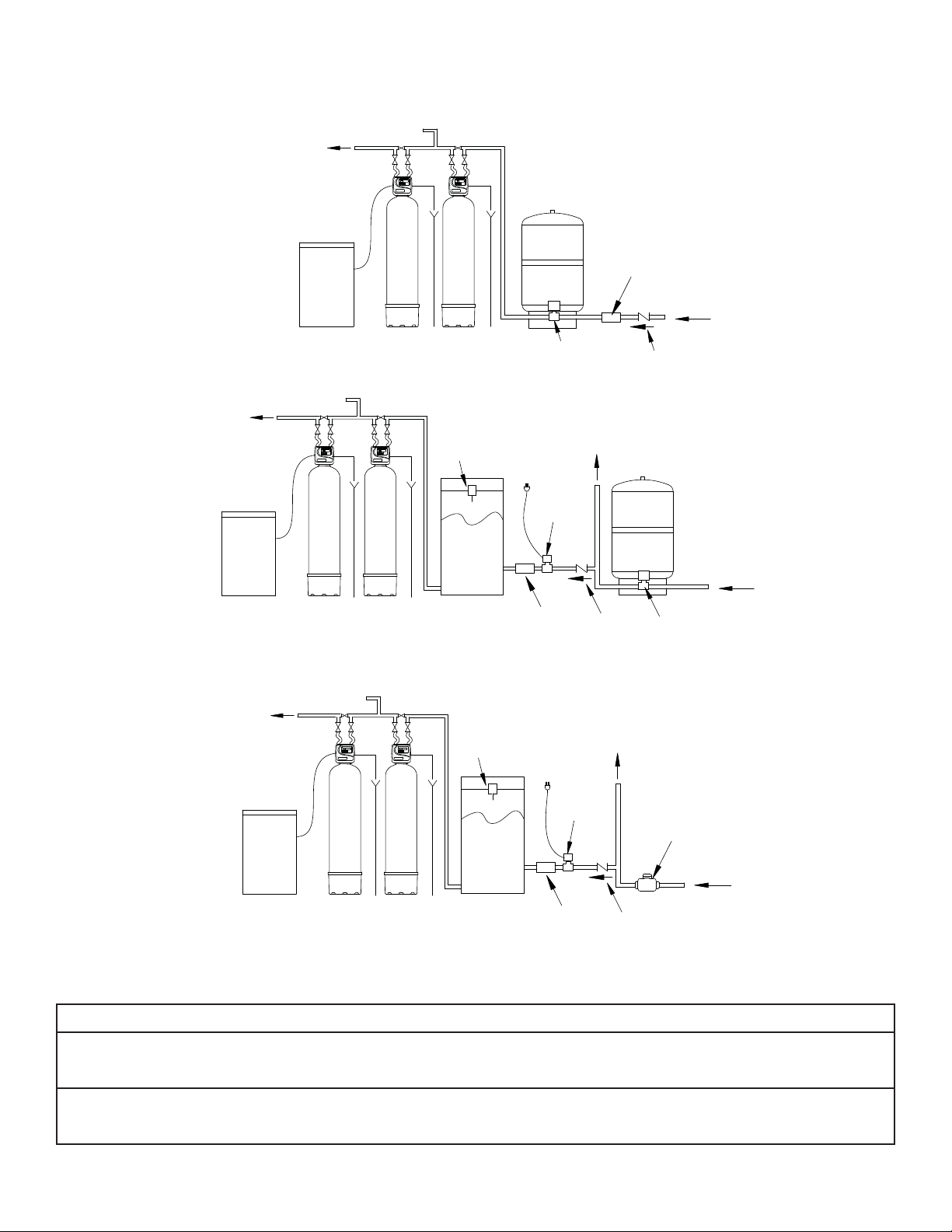
3) Locate in correct relationship to other water conditioning equipment (Figure 1, page 3-1).
4) Locate the system in the supply line BEFORE the water heater. Temperatures above 110°F (43.3°C) will damage the system and void the factory
warranty.
5) DO NOT install the system in a location where freezing temperatures occur. Freezing may cause permanent damage and will also void the factory
warranty.
6) Allow suffi cient space around the installation for easy servicing.
7) Provide a non-switched 110V, 60Hz (220V, 50Hz for specifi ed systems) power source for the control valve.
WARNING
To reduce the risk associated with ingestion of contaminants:
• Do not use with water that is microbiologically unsafe or of unknown quality without adequate disinfection before or after the system.
CAUTION
To reduce the risk associated with property damage due to water leakage:
• Protect from freezing, relieve pressure and drain system when temperatures are expected to drop below 33°F (0.6°C).
• Do not install on hot water supply lines. The maximum operating water temperature of this fi lter system is 110°F (43.3°C).
The Importance of Your Pressure Tank:
The pressure tank found on private well systems becomes an integral part of the iron and manganese reduction system by providing necessary mixing and
“residence time” to the “hydro-charged” water. While the iron and manganese reduction system will perform satisfactorily with either a captive-air (bladder) type
pressure tank or a standard air-to-water type with an air volume control (air-relief valve), the bladder type requires more careful adjustment of the hydro-charger to
prevent gasses from collecting in the pressure tank and the head area of the media tank.
Under more severe operating conditions (low pH, high iron, manganese, and small concentrations of sulfur), a standard air-to-water type pressure tank with an
air-relief valve MUST be used (if a bladder type tank is already in place, do not remove it, install the air-to-water pressure tank between the hydro-charger and the
bladder type tank).
IMPORTANT NOTE
If your pressure tank (or any part of your water system) is not functioning properly, corrective action MUST be taken before installation of your iron
and manganese reduction system.
CAUTION
To reduce the risk associated with property damage due to water leakage:
• Do not use a torch or other high temperature sources near fi lter system, cartridges, plastic fi ttings or plastic plumbing;
• On plastic fi ttings, never use pipe sealant or pipe dope. Use PTFE thread tape only, pipe dope properties may deteriorate plastic;
• Take care when using pliers or pipe wrenches to tighten plastic fi ttings, as damage may occur if over tightening occurs.
To reduce the risk associated with property damage due to plugged water lines:
• Pay particular attention to correct orientation of control valve. Water fl ow should match arrow on control valve. The inlet and outlet of other water treatment
equipment products will vary depending on the control valve brand used.
2-3
Page 8

Facts to Remember While Planning Your Installation:
1) All installation procedures MUST conform to local and state plumbing codes.
2) If lawn sprinkling, a swimming pool, or geothermal heating/cooling or water for other devices/activities are to be treated by the iron and manganese reduction system, a larger model MUST be selected to accommodate the higher fl ow rate plus the backwashing requirements of the iron and manganese
reduction system. Consult your Dealer/Installer or your Dealer/Installer or our Customer Service Department at 1-800-222-7880. for alternative instructions if the pumping rate is insuffi cient.
3) Remember that the iron and manganese reduction system INLET is attached to the pipe that supplies water (i.e. runs to the pump) and the OUTLET
is the line that runs toward the water heater.
CAUTION
To reduce the risk associated with property damage due to plugged water lines:
• Pay particular attention to correct orientation of control valve. Water fl ow should match arrow on control valve. The inlet and outlet of other water treatment
equipment products will vary depending on the control valve brand used.
4) Before commencing the installation it is advisable to study the existing piping system and to determine the size, number and type of fi ttings
required.
WARNING
To reduce the risk associated with a hazardous voltage:
• If the home electrical system requires use of the cold water system as an electrical safety ground, a jumper must be used to ensure a suffi cient ground connection
across the fi lter installation piping — refer installation to qualifi ed personnel.
5) Sweep the fl oor to eliminate objects that could pierce the media tank.
2-4
Page 9
SECTION 3: IMPORTANT INSTALLATION INSTRUCTIONS
Proper installation sequence of water conditioning equipment is very important. Refer to the following diagram for your particular water supply. Failure to follow installation,
operation, and maintenance instructions may result in property damage due to leakage and will void warranty.
TREATED
SOFT WATER
TREATED WATER
TREATED
SOFT WATER
SOFT WATER
BRINE
TREATED
TANK
TREATED WATER
TREATED WATER
BRINE
TANK
WASTE DRAIN
SOFTENER IRON AND
MANGANESE
REDUCTION SYSTEM
WASTE DRAIN
SOFTENER
IRON AND
MANGANESE
REDUCTION SYSTEM
TYPICAL WELL INSTALLATION
AIR
RELEASE
VALV E
SECONDARY
WASTE DRAIN
AIR TO WATER
PRESSURE TANK
SPLIT-STREAM INSTALLATION
AIR
RELEASE
VALV E
WASTE DRAIN
HYDRO-CHARGER
TO
110 V
OUTPUT
PRESSURE
TAN K
PRESSURE
SWITCH
SOLENOID
VALVE
TO
110 V
OUTPUT
WATER FOR
LAWN SPRINKLERS
OR OTHER
HIGH DEMAND
CHECK VALVE
WATER FOR
LAWN SPRINKLERS
OR OTHER
HIGH DEMAND
HYDRO-CHARGER
CHECK VALVE
PRIMARY
PRESSURE
TAN K
PRIMARY
PRESSURE
SWITCH
INCOMING
WELL
WATER
INCOMING
WELL
WATER
SOLENOID
VALVE
CHECK VALVE
METER
INCOMING
WATER
BRINE
TANK
SOFTENER
WASTE DRAIN
IRON AND
MANGANESE
REDUCTION SYSTEM
WASTE DRAIN
SECONDARY
AIR TO WATER
PRESSURE TANK
HYDRO-CHARGER
PUBLIC WATER SUPPLY INSTALLATION
Figure 1
CAUTION
To reduce the risk associated with property damage due to water leakage:
• Read and follow Use instructions before installation and use of this water treatment system.
• Installation and use MUST comply with existing state or local plumbing codes.
To reduce the risk associated with property damage due to plugged water lines:
• Pay particular attention to correct orientation of control valve. Water fl ow should match arrow on control valve. The inlet and outlet of other water treatment
equipment products will vary depending on the control valve brand used.
3-1
Page 10
GRAVEL AND CHEM-FREE MEDIA SCHEDULE
CAUTION
APIF100 Models
Unit Model Number
(APIF100, APIF100DM, APIF100J, APIF100M,
APIF100MDM, APIF100PT, APIF100PTDM,
APIF100MPT, APIF100MPTDM,APIF100MJ)
Filter Media MC-10P
NOTE: If you ordered an “M” model iron and manganese reduction system, the fi lter pack media would be designated by an M at the end of the part
number i.e. MC-10MP.
To load the fi lter media into the media tank please use the follow steps. This is necessary to ensure that the distributor tube has not been pulled up when
the control valve was removed from the top of the media tank.
Step 1
a) Remove from the shipping carton the fi lter unit
b) Carefully remove the control valve from the tank by rotating the valve head assembly to the left (counter-clockwise).
c) Set all items aside for future use. Ensure that the following items have been shipped entirely with the unit to allow for proper and complete installation. I
i. Control valve
ii. Media tank (also a reducing bushing and fl anged adapter on APIF300)
iii. Bypass valve
iv. 1” Male NPT Connection Kit
v. Media (amount will vary by fi lter size)
vi. Distributor Tube
vii. Drain line assembly kit
viii. Parts bag
ix. Hydrocharger
x. Installation and Operating Instructions
xi. Loading funnel
xii. Centering Tool
d) Remove the distributor tube in the tank, set aside and pour the gravel into a clean pail for later use.
e) Reinsert the distributor tube into the tank and ensure the tube is centered in the tank; a dimple is in the center of the tank to help in doing so. Using the
centering tool and cap, cover the distributor tube opening to prevent fi lter media and gravel from entering the distributor tube during the loading of the tank.
f) Threaded Tank Models: APIF100, APIF100J, APIF100PT, APIF100MPT, APIF100MJ, APIF150, APIF150J, APIF150M, APIF150PT, APIF150MPT, APIF150MJ,
APIF200, APIF200J, APIF200PT, APIF200MPT, APIF200MJ, APIF300, APIF300J, APIF300PT, APIF300MPT, APIF300MJ: Place the funnel provided, in the opening
of the media tank to aid in loading the gravel and fi lter media. Pour the QC gravel into the tank slowly. While holding the distributor tube in place, shake the
tank from side to side gently, to aid in leveling the QC gravel. Do not allow gravel to get under the basket of the distributor tube during the loading of gravel.
If this happens, pour out the gravel and remove the distributor tube once again and reload gravel once again. Next locate the fi lter media and slowly pour
into the tank. Again shake the tank from side to side to aid in leveling the media. Next, using a hose or clean pail, fi ll the tank with water to saturate the fi lter
media and expel any air that may be present, remove the extension tube, cap and funnel, and save for future servicing.
g) Dome Hold Tank Models: APIF100DM, APIF100PTDM, APIF100MDM, APIF100MPTDM, APIF150DM, APIF150PTDM, APIF150MDM, APIF150MPTDM, APIF200DM,
APIF200PTDM, APIF200MDM, APIF200MPTDM:
Add media through fi llport cap located on tank using funnel (See FILLING MEDIA TANK below). Fillport cap can be removed by turning a quarter turn counter clockwise.
APIF150 Models
(APIF150, APIF150DM, APIF150J, APIF150M,
APIF150MDM, APIF150PT, APIF150PTDM,
APIF150MPT, APIF150MPTDM, APIF150MJ)
MC-10P
MC-050P
APIF200 Models
(APIF200, APIF200DM, APIF200J, APIF200M,
APIF200DM, APIF200PT, APIF200PTDM,
APIF200MPT, APIF200MPTDM, APIF200MJ)
MC-10P (2) MC-10P (3)
APIF300 Models
(APIF300, APIF300J, APIF300M,
APIF300PT, APIF300MPT, APIF300MJ)
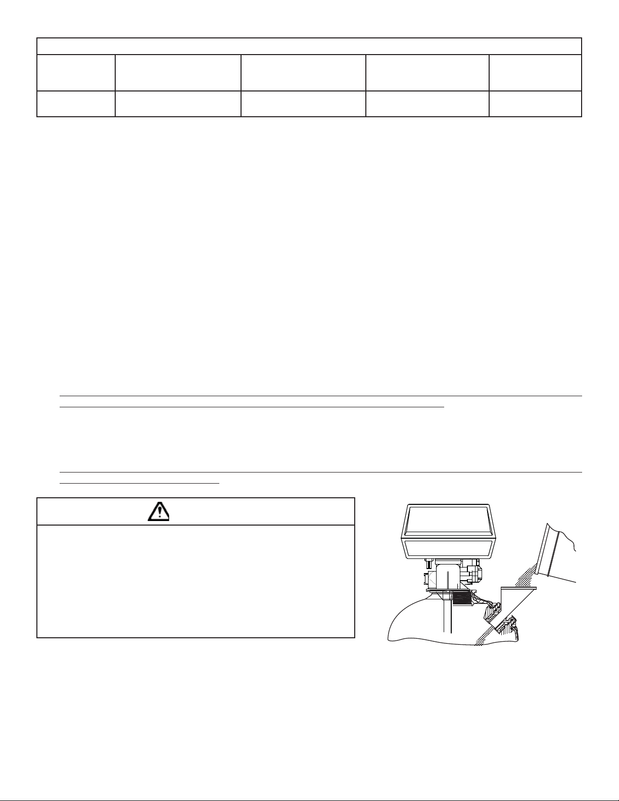
CAUTION
To reduce the risk associated with skin, eye, and respiratory tract irritation from dust
from fi lter media during installation:
• Gravel and several types of fi lter media may be used in this product, depending upon the
application. During installation, dust may cause irritation to skin, eyes, and respiratory
tract, and may affect lungs.
• Utilize a NIOSH-approved dust fi lter mask and appropriate eye protection when handling
and pouring gravel and fi lter media.
• To request an MSDS relating to this product, call 203-238-8965 or go to www.3M.com ,
select country, and use the search engine to search MSDS. For emergencies, call 800-
364-3577 or 651-737-6501 (24 hours).
Reinstall fi llport cap by turning a quarter turn clockwise.
If bypass valve assembly is not factory pre-installed, attach using clips and screws.
FILLING MEDIA TANK
Using a clean dry rag, wipe the opening of the media tank to remove any dust or residue from the opening to receive the control valve. Attach the valve head
to the media tank by rotating the valve head assembly to the right (clockwise).
Step 2
Shut off water at main supply. On a PRIVATE WELL SYSTEM turn off the power to the WELL PUMP and drain PRESSURE TANK. Make certain all water pressure
has been relieved from water system by opening nearest faucet to drain water system. SHUT OFF FUEL SUPPLY TO WATER HEATER OR BOILER.
3-2
Page 11
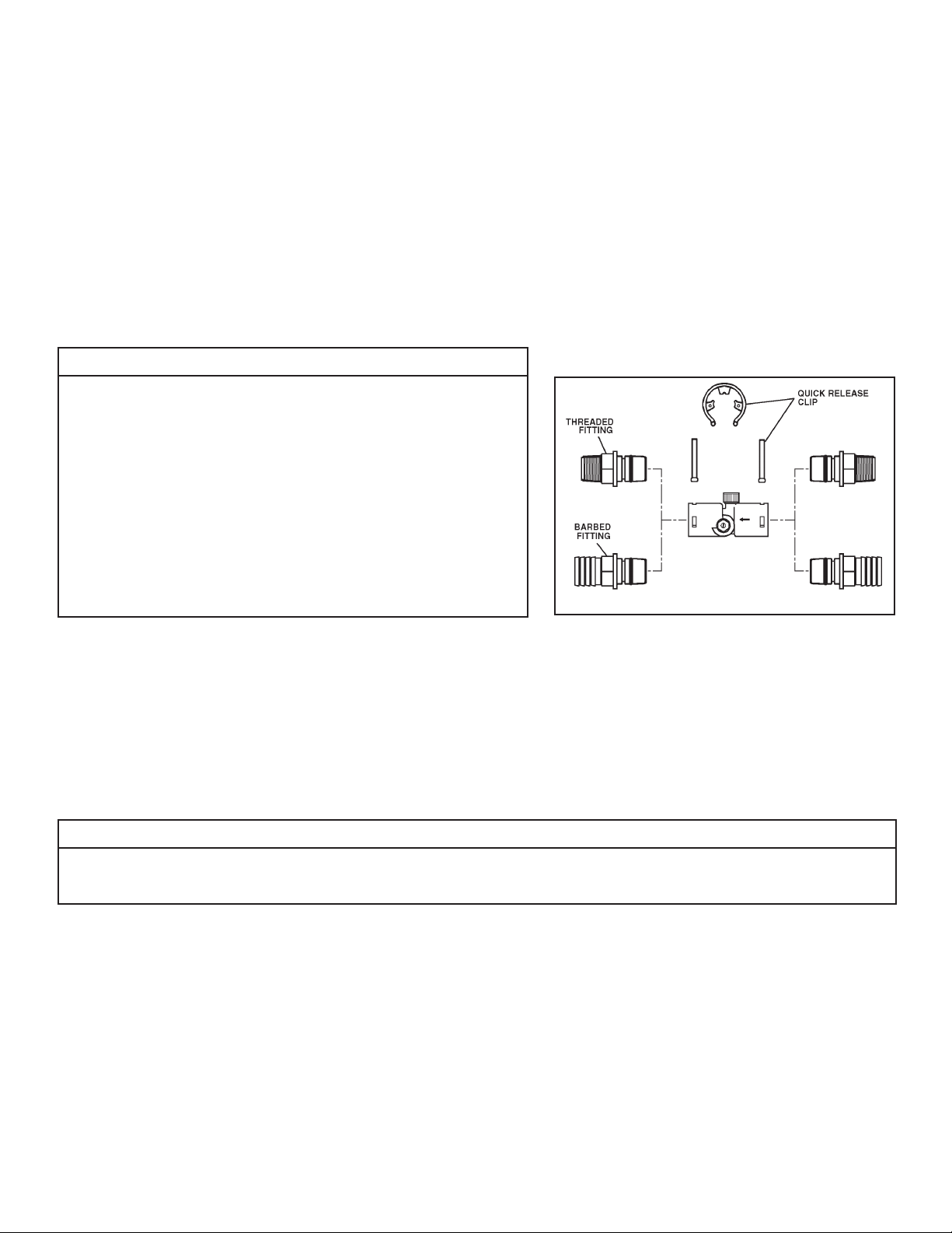
Step 3
Cut main supply line as required to fi t hydro-charger in plumbing between well pump and pressure tank (hydro-charger may be installed in a vertical or
horizontal position). The hydro-charger has been supplied with both 1” threaded and 1” barbed (insert) fi ttings to allow for installation with various types of
piping materials. When using the threaded nipples, use thread tape only. When using barbed (insert) fi ttings, appropriate pipe clamps must be used. Once
installed the quick release nipples allow the hydro-charger to be rotated, so the air draw adjustment screw is accessible for adjustment by a small bladed
screwdriver. Allow at least 10 inches of straight run of 1” pipe on both INLET and OUTLET side of the hydro-charger. Refer to Figure 2 for correct assembly.
The quick release nipples also act as a union to facilitate the hydro-charger removal, inspection and cleaning as needed. With an installation on PVC pipe
and copper tubing it may require the addition of a plumbing union to aid in removal from the plumbing due to the rigidity of that type of material. Make
certain the directional arrows on the hydro-charger point towards the pressure tank and the pressure control switch is located on the pressure tank side
of hydro-charger as in Figure 1. Rapid cycling of pump may occur if the pressure control switch is located on well side. If a check valve is located between
hydrocharger and pressure tank, it may prevent the hydro-charger from performing properly. Relocate to well side of hydro-charger.
Step 4
Turn back on the power to the well pump and pressurize the water lines to allow for adjustment of the hydro-charger. Check for leaks and adjust as necessary.
IMPORTANT NOTES
• Do not apply heat near hydro-charger, as damage may occur. On badly scaled, older
plumbing systems, it may be advantageous to install a WYE STRAINER to help prevent plugging of the hydro-charger nozzle with scale or debris. The use of a WYE
STRAINER must precede the hydrocharger on the inlet side by a MINIMUM OF
10”.
• If existing water system includes a captive-air type pressure tank (bladder) and it is
desirable to install an additional air to water type with an air release (not as a split
steam type installation) install an air to water type pressure tank between the hydro-
charger and the existing captive air type pressure tank.
• Before proceeding with hydro-charger installed, re-verify adequate pumping rate pumping by following the procedure described in SECTION 2. After
verifi cation of adequate fl ow, depressurize system as described previously.
• If installation is to be split streamed prior to tank or is it a public water supply
(see fi gure 1), or refer to special instructions on page 3-11.
Step 5
Set hydro-charger by following the following steps:
a) Open nearest faucet until well pump starts, then close faucet.
b) Place a fi nger lightly over the SUCTION PORT (Figure 4). A slight suction should be detected for approximately ONE THIRD (1/3) of pumping cycle time. (Do not
confuse with ONE THIRD (1/3) of pressure range).
c) If suction is too short, increase by turning air adjustment screw (Figure 4), CLOCKWISE. To decrease duration, turn COUNTER-CLOCK WISE.
d) Repeat steps (a) through (c) until proper setting is obtained. The optimum cycle time is 60 seconds or more, with
an air draw of 20 seconds minimum. Position DRAIN LINE over drain and secure fi rmly. To prevent back-siphoning of sewer water, provide an air gap of at
least 2 inches or 2 pipe diameters between end of drain hose and drain (Figure 6). Do not raise DRAIN LINE more than 10 ft. above fl oor.
Figure 2: Hydro-Charger Installation
IMPORTANT NOTE
When the duration of the suction is too long, the cold water may have a milky appearance caused by excess air in the water system. Correct this condition by reducing the duration of suction. This condition is commonly associated with bladder type pressure tanks. In extreme cases where elimination
of excess air prevents system from performing satisfactorily, it may be necessary to install an air to water pressure tank with an air release valve.
Step 6
Turn off the electrical source to the water well pump or the close the water shut off valve on a municipal water supply to the dwelling once again. Depressurize
the water system by opening the nearest faucet to drain water from the water system in order to allow the installation of the iron and manganese reduction
system.
Step 7
Determine location and cut the water line on the supply side of the pressure tank as required to fi t the plumbing to the control valve connection fi ttings.
You may want to install a separate three valve bypass prior to the control valve in case the supplied bypass valve requires maintenance in order to provide
undisturbed water use.
3-3
Page 12

Step 8
Assemble and attach bypass valve to the control valve. See Figure 3 if needed. Next locate
and assemble the 1” NPT connection fi ttings before attaching them to the bypass valve.
Use the appropriate method of connection to ensure a permanent connection. Please refer
to fi gure 5 to correctly assemble the connection fi ttings. Install the fi tting into the bypass
valve, attach the plumbing to the 1” NPT male connection fi ttings, hand tighten the fi ttings
nuts only. Make certain the water enters inlet and discharges through the outlet side of the
bypass valve. Arrows can be viewed on the bypass valve to confi rm the correct fl ow path. At
this time make certain the bypass valve is in the bypass position and leave in that position
until instructed to place in the service position. Refer to Figure 3 for proper operation.
INOUT
OFF
OFF
DRAIN LINE FLOW
CONTROL ASSEMBLY
NORMAL OPERATIO BN YPASS OPERATION
Treated
Water
Exits
Supply Water
Enters
OFF
OFF
Supply (Untreated)
Water Exits
BYPASS VALVE
CONTROL VALVE BODY
Supply
Water
Enters
OFF
OFF
Figure 3
Figure 4
OFF
OFF
CAUTION
To reduce the risk associated with property damage due to water leakage:
• Do not use a torch or other high temperature sources near fi lter system, cartridges, plastic fi ttings or plastic plumbing;
• On plastic fi ttings, never use pipe sealant or pipe dope. Use PTFE thread tape only, pipe dope properties may deteriorate plastic;
• Take care when using pliers or pipe wrenches to tighten plastic fi ttings, as damage may occur if over tightening occurs.
Step 9
Fitting Installation Instructions
1) The installation fi ttings are designed to accommodate minor plumbing line and fi ttings.
2) Thread tape is the only type of thread sealant allowed to be used; the use of paste of any kind
will void the factory warranty. Do not let the connection fi ttings support the plumbing, properly
support the plumbing as required.
3) Slide the nut on fi rst (closed and against the threads), then slip ring onto the fi tting, ensuring it set
correctly in groove, then the O-ring last. Use silicone lubricant to allow for easier insertion of parts
into one another.
4) Hand tighten the nut only, the use of pliers or wrenches of any type will void the factory warranty
and may cause damage to fi ttings and water will leak in your home or facility.
1
2
3
4
Figure 5
OFF
OFF
OFF
OFF
Use customer supplied fi ttings to adapt the drain line to the control valve. Support of the drain line is required to prevent damage to the drain line elbow which could
lead to a water leak in the dwelling. Suitable drain line material can be Copper, PVC or CPVC pipe, PEX or PE tubing can be used to adapt to the ¾ NPT threads on
the drain elbow for long or high drain lines. Use only thread sealing tape to seal the threads, hand tighten the threaded joint. To utilize polyethylene tubing as a drain
line, remove the supplied nut and fi nd the insert that was shipped in the parts kit bag. Slide the nut over the polyethylene tubing and insert the sleeve into the tubing.
Slide the end of the tubing into the elbow, using your hand thread the nut onto the elbow and hand tighten only. No thread tape is required to seal the threads with
compression fi ttings.
3-4
Page 13

CAUTION
To reduce the risk associated with property damage due to water leakage:
• Take care when using pliers or pipe wrenches to tighten plastic fi ttings, as damage may occur if over tightening occurs.
Typical examples of proper drain line diameters and lengths are:
1/2” ID up to 15 feet when discharge is lower than the inlet.
5/8” ID up to 15 feet when discharging is slightly higher than the inlet.
3/4” ID when drain is 25 feet away and not higher than 4 feet above control valve.
Avoid installing drain line overhead or using fl exible vinyl tubing. Use of either may result in the fi lter not operating properly in reducing iron, manganese or
turbidity. Some areas prohibit the use of fl exible drain lines. Check with the local code offi cials prior to installation to ensure you conform to local, state and
national plumbing codes.
Step 10
Position the DRAIN LINE over the waste drain pipe and secure fi rmly. To prevent back siphoning of
sewer water or grey water, provide an air gap of at least two inches or 2 times the pipe diameters
between the end of drain line tubing and waste drain (Figure 6). Do not raise the DRAIN LINE more
than 10 feet above the fl oor. Check with local code offi cials to ensure you conform to local, state
and national plumbing codes.
Step 11
Plug the control valve into a properly grounded 110 V, 60 Hz non switched electrical outlet. Check
with your local code enforcement offi ce to determine if it meets local codes.
Step 12
Set the time of day by referring to Page 3-8 “How to Set Time of Day”.
EQUIPMENT
DRAIN LINE
DRAIN
AIR GAP
2" REF
Step 13
Open the valve on the water supply as required to pressurize the water lines to the dwelling or fuel
source. The power to the water heater or boiler needs to be established once water has been allowed to fl ow back into the device, if it was drained at any
time during the installation. Turn back on the power or fuel source to either the water heater or boiler if it was drained at any time during the installation.
Check for leaks on all connections before leaving the job site, correct as required.
Figure 6: Drain
Step 14
Manually initiate regeneration of the iron and manganese reduction system by referring to the “How To Manually Initiate Immediate Regeneration” sec-
tion of Control Valve settings on Page 3-8.
Step 15
Once the valve is in the backwash position (C1 appears on the display) slowly open the inlet side of the bypass valve to allow water to fl ow into the tank.
Water should start to fl ow into the drain. Allow for any air that might have been trapped to leave the fi lter and go to drain. This will be detected by changes
in noise in the drain line or is visible in the semi-transparent tubing. Once the air is entirely gone slowly increase the water fl ow to drain by opening the inlet
side of the bypass valve until fully open. Refer to Figure 3 for correct positioning. At the end of C1 position the water should be clear. If not, allow the valve to
complete the manual regeneration process and initiate once again. It is very important to allow the unit to purge all fi nes to the waste drain from the media
in the tank prior to using the water. Once the fl ushing process has been completed you now can open the outlet side of the bypass valve to allow for fi ltered
water to fl ow into the dwelling.
IMPORTANT NOTES
Due to the nature of the iron reduction media, on start up it sometimes requires 2 or 3 days for the iron and manganese reduction system to reduce
Iron and Manganese below staining levels. Do not be alarmed if this occurs. During the initial start up and subsequent fi rst couple automatic regeneration cycles, a small amount of fi ne white and beige media may be observed in the drain water and or drain area. This is normal and benefi cial for the
effi cient operation of your iron and manganese reduction system.
Step 16
The frequency of backwash is factory preset at every 4 days. If the iron content is greater than 5 ppm, is red water or bacterial iron the unit should be washed
more frequently. See tables to determine the frequency. Also if the water has tannin-lignin or hydrogen sulfi de present, the fi lter should backwash every day.
Refer to Section 4 for backwashing instructions and frequency.
3-5
Page 14

BACKWASH FREQUENCY SCHEDULE
Models: APIF100, APIF100DM, APIF100J, APIF100M, APIF100MDM, APIF100PT,
APIF100PTDM, APIF100MPT, APIF100MPTDM and APIF100MJ
Persons
in
Family
1
2
3
4
5
6
246810121416
12 12 12 12 12 12 12 12
12121266666
1212666444
1212664443
1212664333
126643222
IRON CONTENT - (PPM).
Models: APIF150, APIF150DM, APIF150J, APIF150M, APIF150MDM, APIF150PT,
APIF150PTDM, APIF150MPT, APIF150MPTDM and APIF150MJ
Persons
in
Family
1
2
3
4
5
6
7
8
246810121416
12 12 12 12 12 12 12 12
12 12 12 12 12 12 6 6
121212126664
12121266644
12121266443
12121264443
66444322
64443222
IRON CONTENT - (PPM)
3-6
Page 15

Models: APIF200, APIF200DM, APIF200J, APIF200M, APIF200MDM, APIF200PT, APIF200PTDM, APIF200MPT,
APIF200MPTDM and APIF200MJ
Persons
in
Family
5 1012141618202224262830
1 121212121212121212121212
2 1212121212121266666
3 121212666666644
4 12126666644444
5 1266644444333
6 1266444433322
7 1264433332222
8 1264433322222
9 644333222211
10 643332222111
as this is the upper limit of iron we recommend this product to be placed on.
The total amount of iron should not exceed 15 ppm
IRON CONTENT - (PPM)
Models: APIF300, APIF300J, APIF300M, APIF300PT, APIF300MPT, and APIF300MJ
Persons
in
Family
The total amount of iron should not exceed 15 ppm
as this is the upper limit of iron we recommend this product to be placed on.
10 12 14 16 18 20 22 24 26 28 30 32
IRON CONTENT - (PPM)
1 121212121212121212121212
2 1212121212121212121212 6
3 12121212612666666
4 121212666666664
5 12126666664444
6 1266646444433
7 666644446333
8 666444433332
9 664444333222
10 664443332222
Step 17
The installation of your iron and manganese reduction system is now complete. If your water system installation is something other than a private well sys-
tem, please familiarize yourself with the SPECIAL INSTRUCTIONS FOR SPLIT-STREAM AND PUBLIC WATER SUPPLY TYPE INSTALLATIONS on page 3-11.
3-7
Page 16

HOW TO SET TIME OF DAY
STEP 1
SET
STEP 2
Regen
Min. Fill
Regen
Time
STEP 3
Regen
Min. Fill
Regen
Time
Regen
Min. Fill
Regen
Time
SET
SET
SET
Step 1) Press SET
Time
PM
Step 2) Use ▲ and ▼ to adjust the current time hour. Time display will be 12 hour with PM indicator with 60 Hz line fre-
Days To
Regen
quency detection on power-up. Time display will be 24 hour without the PM indicator with 50 Hz line frequency on
power-up. Press SET and proceed to step 3.
Time
PM
Days To
Regen
Step 3) Use ▲ and ▼ to adjust the current time minutes. Press SET to exit Set Time of Day.
Power Loss
Time
If power is lost for more than 8 hours, the current time of day will need to be reset. If the system is in the middle of regeneration
PM
Days To
Regen
upon power loss, the control will continue regeneration at the point of interruption when power is restored.
Error Message
Contact our technical servcie department at 800-222-7880 for assistance if the display shows “E1,” “E2,” “E3” or “E4.” These
messages are indications the valve did not function properly.
Arrow will point to Regen if a
regeneration is expected “Tonight.”
Regen
Min. Fill
Regen
Time
SET
HOW TO MANUALLY INITIATE IMMEDIATE REGENERATION
If a system needs to be regenerated before the next scheduled time, manual regeneration can be initiated. This may be necessary during times of heavy water usage, including house guests or heavy laundry days.
Time
To initiate an immediate manual regeneration, press ▲ and ▼ simultaneously for three seconds. This request cannot be can-
PM
Days To
celled.
Regen
HOW TO MANUALLY INITIATE DELAYED REGENERATION
To initiate a manual regeneration at the preset delay time, press ▲ and ▼ simultaneously. Release. An arrow will point to REGEN
if regeneration is expected “tonight.” To cancel, press ▲ and ▼ simultaneously. Release.
3-8
Page 17

TO SET TIME OF REGENERATION AND DAYS BETWEEN REGENERATION
STEP 1
SET
STEP 2
Regen
Min. Fill
Regen
Time
SET
STEP 3
Regen
Min. Fill
Regen
Time
SET
STEP 4
Regen
Min. Fill
Regen
Time
3 seconds
SET
Time
PM
Days To
Regen
Time
PM
Days To
Regen
Time
PM
Days To
Regen
Follow these steps for inital set-up of or to make adjustments to the time of regeneration and/or the days
between regenerations. The number of days between regenerations may need to be varied based on usage
and water conditions.
STEP 1
Press “SET” and ▲ for approximately 3 seconds. (This step will not appear if the 7-day clock option is
selected.)
STEP 2
Set Regeneration Time Hour. Set the time for regeneration to start using the ▲ and ▼ arrows. Press SET to
go to the next step.
STEP 3
Set Regeneration Time Minutes using the ▲ and ▼ arrows. Press SET to go to the next step.
STEP 4
Set Number of Days between regeneration cycles using the ▲ and ▼ arrows.
STEP 5
Press SET to complete and return to normal operation.
HOW TO CHANGE THE REGENERATION PROGRAM SETTINGS
STEP 1 - Press and hold SET HOUR and buttons simultaneously until the display begins fl ashing (usually
about three (3) seconds).
STEP 2 - Press and hold SET HOUR and
about three (3) seconds).
STEP 3 - Press the SET HOUR to change the display to P8 or P9.
STEP 4 - Press the SET HOUR button fi ve (5) times to return to the display mode. The time of day should be in
the display.
buttons simultaneously until the display begins fl ashing (usually
3-9
Page 18

Control Valve Function and Cycles of Operation
The AC adapter comes with a 15 foot power cord that is designed for use with the control valve. The AC adapter is for dry location use only. If the power
goes out, only the time of day needs to be reset. All other settings are permanently stored in the non-volatile memory.
The following chart shows the time for the backwash and rapid rinse cycles for the three available programming options.
Regeneration Cycles and Times for Different Programs
Program Number Length of Cycle Times (Minutes)
BACKWASH (C1) RAPID RINSE (C4)
P7 6 4
P8 10 6
P9 14 8
Note: Your iron and manganese reduction system is factory preset to program number P7, changing the setting to P8 or P9 is rarely
needed. But if a change is desired, please refer to “How to Change the Regeneration Program Settings” on page 3-9.
USER DISPLAYS
General Operation
When operating, the system will either display the current time of day or the days remaining until the next regeneration. Use ▲ or ▼ to toggle between the two displays. If the remaining days is at 1, the system will regenerate
at the preset time.
An arrow will appear pointing to REGEN when the system calls for regeneration.
Regeneration Mode
When the system is regenerating, untreated water will be used. Therefore, systems are typically set to regenerate
during times of low water usage—such as when the household is asleep.
During regeneration, the arrow will point to REGEN and the display will change to Regeneration Cycle Display,
indicating the time remaining. The system automatically runs through the steps of regeneration; upon comple-
tion, treated water is ready for use.
Arrow will point to Regen
if a regeneration is
expected “Tonight.”
Regen
Min. Fill
Regen
Time
SET
Regen
Min. Fill
Regen
Time
SET
Time
PM
Days To
Regen
Time
PM
Days To
Regen
3-10
Page 19

CAUTION
To reduce the risk associated with property damage due to water leakage:
• Installation and use MUST comply with existing state or local plumbing codes;
Special Instructions for Split-Stream and Public Water Supply Type Installations:
For a split-stream type installation, a secondary air-to-water pressure tank must be installed as in Figure 1. On a public water supply type installation, a pressure
tank must be installed as in Figure 1. It is recommended in both applications to use a standard air-to-water type pressure tank with a deep well air volume control (air release valve). The pressure tank should be of same capacity as would normally be installed if the water system were a standard private well. Also note,
both applications require a 1” normally-closed solenoid valve. Follow standard installation procedures above with the following additions and modifi cations.
1) Install a secondary air-to-water pressure tank in Figure 1 as indicated by the appropriate diagram.
2) Install a normally-closed solenoid valve, 110, 60Hz after water meter and after a line split for untreated water (if there is one). The use of a check valve
in the water line is highly recommended.
3) On both types of installation, install the hydro-charger between the normally-closed solenoid valve and pressure tank (secondary air-to-water pressure
tank on split-stream type installation) maintaining a minimum of 10” on both inlet and outlet of hydrocharger.
4) Install the pressure switch after hydro-charger and wire it to the secondary pressure switch on the split-stream. Power for the secondary pressure
switch should be provided by a separate 110V, 60 Hz source for the split stream installation. For public water supply installation, power for the pressure switch should also be provided by a separate 110V, 60 Hz power source. Set the high pressure on the pressure switch (which controls opening and
closing of solenoid valve) 2 to 3 psi lower than low pressure on primary pressure switch. Example: if the primary pressure switch is set at 40/60 psi, set
the secondary pressure switch at 20/38 psi. For public water supply type installations, contact your local water department or plant operator and ask
what the normal low system pressure is. Set the high pressure on the pressure switch 2 to 3 psi lower than this figure.
IMPORTANT NOTE
Failure to set PRESSURE SWITCH as described above will NOT allow proper closing of SOLENOID VALVE during periods of low system pressure. Improper function of SOLENOID VALVE will cause total failure of system.
Special Service Instructions:
Under normal circumstances removal of valve should never be required. However, if it must be removed, it can be done by rotating the valve head assembly to the
left (counter-clockwise). Pressure should be relieved before attempting any disassembly. Upon reassembly, all O-rings should be lubricated with silicone grease.
3-11
Page 20

Figure 7
Figure 8
Figure 9
Figure 10
3-12
Page 21

Section 4: BACKWASHING INSTRUCTIONS
Periodic regeneration of the iron and manganese reduction system bed is required to fl ush out the entrapped iron that has accumulated. This procedure is performed
automatically at 1:00 a.m. for a period of approximately 10 minutes and will not interfere with a softener regeneration, which is usually set for 2:00 a.m.
TO SET BACKWASH FREQUENCY FOR NORMAL HOUSEHOLD APPLICATIONS:
To determine and set Backwash Frequency, follow these instructions:
1) Select Backwash Frequency Schedule corresponding to your model (page 3-6 and 3-7).
2) Locate box intersected by number of persons in your family and iron content of water (if iron concentration is between two numbers in Schedule,
use higher number.)
3) Number in box represents number of days, between regenerations. Refer to How to Set Time of Regeneration and Days Between Regeneration on page
3-9.
Example: You have model APIF100, 4 people in family, and 8 ppm iron. Refer to Schedule for model APIF100 and locate box intersected by 4 in family and 8 ppm iron. The
fi gure indicates 6 as the the number of days between each regeneration period.
IMPORTANT NOTE
The Backwashing Frequency Schedules are based on average water consumption rates and are merely guides. They are NOT intended to be used if
water is used by outside spigots, a swimming pool, geothermal heat pump, or other high water usage devices or activities.
4-1
Page 22

Section 5: TROUBLESHOOTING - CONTROL VALVE
Problem Possible Cause Solution
1. Timer does not display time of day a. AC adapter unplugged a. Connect power
b. No electric power at outlet b. Repair outlet or use working outlet
c. Damaged AC adapter c. Replace C Adapter
d. Damaged PC board d. Replace PC board
2. Timer does not display correct time of day a. Switched outlet a. Use an unswitched outlet
b. Time of day not set correctly b. Reset time of day
3. Control Valve regeneration at wrong
time of day
4. Error followed by a code number
Error code E1- Unable to recognize
start of regeneration
Error code E2- Unexpected stall
Error code E3- Motor ran too long.
Timed out trying to reach next cycle
position
If other codes appear contact factory
5. Control valve stalled in regeneration a. Motor not operating a. Replace motor
a. Power outages a. Reset control valve to correct time of day
b. Time of day not set correctly b. Reset to correct time of day
c. Time of regeneration incorrect c. Reset regeneration time
a. Control valve has just been serviced a. Press SET HOUR and DOWN for 3 seconds
or unplug power source jack (black wire)
from the circuit board and plug back in to
reset control valve
b. Foreign matter is lodged in control valve b. Check piston and spacer stack assembly
for foreign matter
c. High drive forces on piston c. Replace piston(s) and spacer stack assembly
d. Control valve piston not in home position d. Press SET HOUR and DOWN for 3
seconds or unplug power source jack
(black wire) from the circuit board and
plug back in to reset control valve.
e. Motor not inserted fully to engage pinion, motor
wires broken or disconnected, motor not working
properly.
f. Drive gear label dirty or damaged, missing or broken
gear
g. Drive bracket incorrectly aligned to drive bracket g. Reseat drive bracket properly
h. PC board incorrectly aligned to drive bracket h. Replace PC board
i. PC board incorrectly aligned to drive bracket i. Ensure PC board is correctly snapped on to
b. No electric power at outlet b. Repair outlet or use working outlet
c. Damaged AC adapter c. Replace AC adapter
d. Damaged PC board d. Replace PC board
e. Check motor and wiring. Replace motor if
necessary
f. Replace or clean drive gear
drive bracket
6. Control valve does not regenerate
automatically when UP and DOWN
buttons are depressed and held.
7. Control valve does not regenerate
automatically, but does when UP and
DOWN buttons are depressed and
held
e. Broken drive gear or drive cap assembly e. Replace drive gear or drive cap assembly
f. Broken piston retainer f. Replace piston retainer
g. Broken main or regenerant piston g. Replace main or regenerant piston
a. AC adapter unplugged a. Connect AC adapter
b. No electric power at outlet b. Repair outlet or use working outlet
c. Broken drive gear or drive cap assembly c. Replace drive gear or drive cap assembly
d. Damaged PC board d. Replace PC board
a. Damaged PC board a. Replace PC board
b. Set-up error b. Check control valve set-up procedure
5-1
Page 23

Section 5: TROUBLESHOOTING - FILTER UNIT
Problem Possible Cause Solution
1. Water CLEAR when drawn, turns RED upon standing
(stain producing)
2. Water RED when drawn from tap a. Filter bed overloaded with precipitated iron due to
3. Excessive pressure loss through fi lter a. Filter bed overloaded with precipitated iron. a. Refer to Section 2 above.
a. Insuffi cient air-draw by hydro-charger. a. Check hydro-charger adjustment. If unable to
b. Bypass open or leaking b. Close bypass valve and/or repair as necessary.
c. Filter bed overloaded with precipitated iron due to
insuffi cient backwash, or failure to backwash due
to malfunction of control timer or unplugged
control valve power cord.
d. Presence of manganese or tannins. d. Recheck water analysis
e. Flow rate excessive for model. e. Reread Sec. 2, FACTS TO REMEMBER WHILE
f. Check-valve located between Hydro Charger and
pressure tank, disrupting water fl ow.
g. Pumping cycle too short, limiting residence time in
pressure tank (may be water-logged).
h. pH of treated water too low (should be 7.0 or
higher; with manganese, pH must be 8.2).
insuffi cient backwash fl ow rate.
b. Filter bed over loaded with precipitated iron due
to insuffi cient backwash, or failure to backwash
due to malfunction of control timer or unplugged
control valve power cord.
c. Hydro-charger drawing too much air, causing early
precipitation of iron.
d. Hydro-charger installed too far from pressure tank
or pressure tank located too far from media tank
causing iron to precipitate before media tank.
e. Solenoid valve (SPLIT-STREAM or PUBLIC WATER
SUPPLY type installation) malfunction or inadequate
supply system pressure/fl ow rate.
b. Control inlet/outlet valve(s) not fully open. b. Open as necessary.
c. Sand, silt or mud collecting in fi lter bed. c. Check well for these conditions.
d. Filter bed not properly “classifi ed.” d. Manually backwash to reclassify.
e. “Cementing” or “channeling” of fi lter media. e. Prod (stir) fi lter bed to break up hardened layer.
adjust for long enough draw, check pumping rate.
c. Upon correction of problem (increase backwash
frequency if problem determined to be insuffi cient
frequency), manually backwash until backwash water
starts to clear ( in more severe iron fouling cases, fi lter
bed may need chemical cleaning - contact dealer).
PLANNING YOUR INSTALLATION.
f. Relocate check-valve.
g. Correct condition.
h. Replenish pH Plus component in media (contact dealer).
a 1. Recheck well pumping rate and repair or replace
as required.
2. Check for obstructions or kink in drain line.
3. Check for improper drain line fl ow controller (see
specs.) Upon correction of this problem, if
manually backwashing does not clear bed of
iron, fi lter bed may need chemical cleaning - contact
dealer.
b. Upon correction of problem (increase backwash
frequency if problem determined to be insuffi cient
frequency), manually backwash until backwash
water starts to clear (in more severe iron-fouling
cases, fi lter bed may need chemical cleaning - contact
dealer).
c. Reduce hydro-charger air-draw.
d. Relocate to a location closer to fi lter inlet.
e. Repair or replace solenoid valve and verify adequate
supply system pressure and fl ow rate.
Increase backwash frequency to prevent reoccurrence.
4. “Milky” or “bubbly” water (Appears to contain
small bubbles)
a. Excess hydro-charger air-draw. a. Check adjustment for duration of draw in excess
b. Excess gases in water (carbon dioxide, hydrogen
sulfi de, methane).
5-2
of one-third pumping cycle (see Sec.3, Step 10).
b. May require draining of water system or installation of
air-relief control on the fi ll port cap of valve adapter
base, (contact dealer).
Page 24

Section 6: VALVE SPECIFICATION AND OPERATING DATA
Maximum Service Flow Rate:
Includes Bypass Valve
Maximum Backwash Flow Rate:
Includes Bypass Valve
27 gpm (102.2 lpm) @ 15 psig (103 kPa) drop
27 gpm (102.2 lpm) @ 15 psig (103 kPa) drop
Minimum/Maximum Operating Pressure: 20 psi (138 kPa) - 125 psi (862 kPa)
Minimum/Maximum Operating Temperature: 40°F (4.4°C) - 110°F (43.3° C)
AC Adapter:
Supply Voltage
Supply Frequency
Output Voltage
Output Current
Drain Line Flow Control Unit Size Number on
U.S.
120 V. AC
60 Hz
12 V. AC
500 mA
Backwash Flow
Drain Line
Flow Control
1.0 ft
1.5 ft
2.0 ft
3.0 ft
3
3
3
3
053 5.3 20.1
053 5.3 20.1
075 7.5 28.4
100 10.0 37.9
Inlet/Outlet Tube Opening (a) 1” Universal Elbow
(b) 1” Straight brass sweat fi tting
(c) 1” Plastic male NPT fi tting
Distributor Tube Opening 1.05” OD (3/4 NPS)
Tank Thread 2 1/2”- 8 NPSM to Flanged Adapter
Control Valve Weight 4.5 lbs. (2.0 kg)
PC Board Memory Nonvolatile EEPROM
(electronic erasable programmable read only memory)
Rate (gpm)
Backwash Flow
Rate (lpm)
Note: After completing any valve maintenance involving the drive assembly or the drive cap assembly and pistons, unplug the power source from the
jack on the printed circuit board (black wire) and plug back in. This resets the electronics and establishes the service piston position.
6-1
Page 25

Section 6: SPECIFICATION AND OPERATING DATA
ITEM
Media Volume, cu. ft. (cu. mtr.) (Note 1):
Gravel Underbed, lbs. (kg)
Nominal Capacity, ppm-gal.
Operating Service Flow Rate, gpm (lpm) (Note 2):
Pressure Loss @ Service Flow Rate, psi (kPa)
Backwash Flow Rate, gpm (lpm) Note 3
Service Pipe Size, in. (cm) (Note 4)
Media tank Diameter x Height, in. (cm)
Minimum Space Required, in. (cm):
Width
Depth (w/Bypass)
Height
APIF100
APIF100DM
APIF100J
APIF100M
APIF100MDM
APIF100PT
APIF100PTDM
APIF100MPT
APIF100MPTDM
APIF100MJ
1.0 (0.03)
13 (5.9)
30,000
6 (22.7)
5 (34.5)
5.3 (20.1)
1 (2.5)
10 x 44
(26 x 112)
12 (30)
16 (41)
53 (135)
APIF150
APIF150DM
APIF150J
APIF150M
APIF150MDM
APIF150PT
APIF150PTDM
APIF150MPT
APIF150MPTDM
APIF150MJ
1.5 (0.04)
13 (5.9)
45,000
7 (26.5)
7 (48.2)
5.3 (20.1)
1 (2.5)
10 x 54
(26 x 137)
12 (30)
16 (41)
63 (160)
APIF200
APIF200DM
APIF200J
APIF200M
APIF200MDM
APIF200PT
APIF200PTDM
APIF200MPT
APIF200MPTDM
APIF200MJ
2.0 (0.06)
18 (8.2)
60,000
9 (34.1)
8 (55.1)
7.5 (28.4)
1 (2.5)
12 x 54
(30 x 137)
12 (30)
16 (41)
63 (160)
APIF300
APIF300J
APIF300M
APIF300PT
APIF300MPT
APIF300MJ
3.0 (0.08)
26 (11.8)
90,000
12 (45.4)
10 (68.9)
10 (37.9)
1 (2.5)
14 x 65
(36 x 165)
13 (33)
16 (41)
74 (188)
Approximate Shipping Weight, lbs. (kg)
143 (64.9)
186 (84.4)
257 (116.6)
353 (160.2)
Maximum Operating Temperature 110°F (43.3°C); Electrical requirements 110V/60Hz; Operating Pressure 20 -125 psi (138-861
kPa). Specifi cations subject to change without notice.
IMPORTANT NOTE
1) Replenishment of pH adjusting component of media may be required periodically, the frequency of which is dependent on raw water pH,
manganese concentration and water consumption rate. Consult dealer for more information.
2) For satisfactory performance, indicated durations should not be exceeded. Flow rates specifi ed are adequate for normal residential applications. Do not use Service or Peak fl ow rates when sizing commercial applications or if treated water is to supply a geothermal heat pump,
swimming pool, etc. (contact dealer before selecting equipment). Service fl ow rates have been tested against NSF Standard 42 and have a
rated pressure drop of less than 10 psi.
3) For system to operate properly, pumping rate of well pump MUST be suffi cient to backwash unit at rate specifi ed.
6-2
Page 26

Section 6: COMPONENT PARTS LIST
APIF150
APIF150DM
APIF150J
APIF150M
APIF150MDM
APIF150PT
APIF150PTDM
APIF150MPT
APIF150MPTDM
APIF150MJ
Ref.
No.
Description
APIF100
APIF100DM
APIF100J
APIF100M
APIF100MDM
APIF100PT
APIF100PTDM
APIF100MPT
APIF100MPTDM
APIF100MJ
1 Control Valve, Complete, Less Bypass Valve W217530-003-0N W217530-003-0N W217750-003-0N W217000-003-0N
1a O-ring (Included with Item #1) V3180 V3180 V3180 V3180
2 Bypass Valve V3006 V3006 V3006 V3006
3 Standard Media Tank w/Base 6236001-1044 6236001-1054 6236001-1252 6236001-1465
3a Dome Hole Media Tank w/Base 6238601-1044 6238601-1054 6238601-1252 n/a
4 Distributor Tube 6236435 6236437 6236436 6236438
5 Filter Media Standard Models
Manganese Models (M)
MC050P (2)
MC-050MP
MC-075P (X2)
MC-075MP (X2)
6 Gravel Underbed QC-15P QC-15P QC-18P QC-25P
7 Hydro-charger, Complete HC10 HC10 HC10 HC10
8 Quick Release Clip QRC20 QRC20 QRC20 QRC20
9 Air Check Cap HC10-2 HC10-2 HC10-2 HC10-2
10 Air Check HC10-10 HC10-10 HC10-10 HC10-10
O-ring; Bypass Screw HC10-4 HC10-4 HC10-4 HC10-4
11
Bypass Screw HC10-5 HC10-5 HC10-5 HC10-5
12
Screw Retainer HC10-6 HC10-6 HC10-6 HC10-6
13
14 Nipple; 1” NPT (Qty 2, Includes Items #12 & 20) PKNPL100 PKNPL100 PKNPL100 PKNPL100
15 Nipple; 1” Barbed (Qty 2, Includes Items #12 & 20) PKNPL100-BARB PKNPL100-BARB PKNPL100-BARB PKNPL100-BARB
16 O-ring ORG-214 ORG-214 ORG-214 ORG-214
17 Nipple Kit (Includes Items #12, 18, 19, & 20) IKIT-BARB IKIT-BARB IKIT-BARB IKIT-BARB
22 Repair Kit (Includes Items #14 & 15) HC10-RK HC10-RK HC10-RK HC10-RK
APIF200
APIF200DM
APIF200J
APIF200M
APIF200MDM
APIF200PT
APIF200PTDM
APIF200MPT
APIF200MPTDM
APIF200MJ
MC-050P (4)
MC-050MP
APIF300
APIF300J
APIF300M
APIF300PT
APIF300MPT
APIF300MJ
MC050P (6)
MC-050MP (6)
Items Not Shown
Description of Item Part Number
Wrench V3193-01
Vertical Bypass Adapter V3191-01
Standard Funnel U1006
Dome Hole Funnel 6238731
Tube Extension Device and Cap CENTERTOOL
1” Plumbing Connection Fitting
- Straight Male NPT Fitting
- Straight Brass Sweat Connection
V3007-04
V3007-02
* see assembly drawings for individual components.
1
OFF
OFF
2
OFF
OFF
8
7
1a
9
14
3
10
1616
17
14
4
15
5
16
11
16
15
12
13
6
6-3
Page 27

Section 6: COMPONENTS ASSEMBLIES
4a
IRON AND MANGANESE REDUCTION SYSTEM ASSEMBLIES AND COMPONENTS DRIVE CAP ASSEMBLY,
DOWNFLOW PISTON, AND SPACE STACK ASSEMBLIES
Reference No. Part No. Description Quantity
1 V3005 Spacer Stack Assembly 1
2 V3004 Drive Cap Assembly 1
3 V3178 Drive Back Plate 1
4 V3001 Piston Downfl ow Assembly 1
6 V3135 O-ring 228 1
7 V3180 O-ring 337 1
8 V3105 O-ring 215 Pilot Tube 1
NOT SHOWN V3001 Downfl ow body Assembly 1
3
1
2
4b
4
7
8
6
6-4
Page 28

Section 6: FRONT COVER AND DRIVE ASSEMBLY
Reference No. Part No. Description Quantity
1 V3175TC-01 Time Clock Front Cover Assembly 1
2 V3107-01 Motor 1
3 V3106-01 Drive Bracket & Spring Clip 1
4 V3108TC Time Clock PC Board 1
5 V3110 Drive Gear 12 x 36 1
6 V3109 Time Clock Cover 1
V3002TC Time Clock Drive Assembly 1
NOT SHOWN V3186 AC Adapter 110V - 12V 1
Drawing number parts 2 through 6 may be purchased as a complete assembly, part V3202.
1
4
6
5
3
2
6-5
Page 29

Section 6: QUICK CONNECT BYPASS
Part Number V3006
Reference No. Part No. Description Quantity
1 V3151 Nut 1” Quick Connect 2
2 V3150 Split Ring 2
3 V3105 O-ring 2
Not Shown Part# V3191-01 Vertical Bypass Adapter
V3151 1” Quick Connect Nut 2
V3150 Split Ring 2
V3105 O-ring 215 2
V3191 Vertical Bypass Adapter 1
1
2
3
1
2
3
6-6
Page 30

Section 6: INSTALLATION FITTING AND ASSEMBLIES
Quick Connect Assemblies
Part # V3007-02
1” Copper Brass Sweat Adapter
Reference No. Part No. Description: 1” Brass Sweat Assembly Quantity
1 V3151 1” Quick Connect Nut 2
2 V3150 1” Quick Connect Split Ring 2
3 V3105 1” Quick Connect O-Ring 215 2
4 V3188 1” Quick Connect Brass Sweat Assembly 2
4
3
Reference No.
1 V3151
2 V3150
3 V3105
4 V3164
1
2
Part # V3007-04
1” Plastic Male NPT Assembly
Part No. Description Quantity
1” Quick Connect Nut
1” Quick Connect Ring
1” Quick Connect O-Ring 215
1” NPT Quick Connect Plastic Male Assembly
2
2
2
2
4
1
2
3
6-7
Page 31

Reference
Part No. Description Quantity
No.
1 H4615 Elbow Locking Clip 1
2 PKP10T58S-BLK 5/8” Insert Sleeve 1
3 V3192 Quick Connect 3/4” Drain Elbow Nut 1
4 V3158-01 Quick Connect 3/4” Drain Elbow 1
5 V3163 O-ring 019 1
6 V3159-01 Drain Line Flow Control Retainer Assembly 1
7 V3162-042 4.2 gpm Drain Line Flow Control Button 1
7 V3162-053 5.3 gpm Drain Line Flow Control Button 1
7 V3162-075 7.5 gpm Drain Line Flow Control Button 1
7 V-3262-100 10.0 GPM Drain Line Flow Control Button 1
2
3
4
Water
Flow
Proper DLFC orientation
directs water flow towards
the washer face with
rounded edge.
5
6
1
7
6-8
Page 32

Section 7: MAINTENANCE
Plumbing System Clean-Up
For your new system to operate properly, you may need to clean the entire plumbing system of the precipitated iron that has collected in it or iron “bleed”
(staining) will continue to be a problem. The plumbing system includes all water treatment equipment (such as water softeners), water heaters, toilets, and
dishwashers. Please refer to the appropriate owner’s manual for instructions.
General Maintenance
Depending on your water quality, it may be necessary to perform maintenance on your fi lter system in order to ensure continued performance. This is due to low
pH, high manganese and/or the sacrifi cial nature of the fi lter media. The severity of your pH or the amount of water used will determine how often the fi ltration
system will need to be serviced. pH Plus is a pH boosting material that replenishes the same material that was dissolved into your water to make iron and manganese reduction possible. ph PLUS can be purchased through your Dealer/Installer or our Customer Service Department at 1-800-222-7880.
3M Purifi cation Inc. recommends that you test your treated water pH once a quarter. When iron is the only problem, a water pH needs to be 7.2 higher. When
Manganese and Iron are present, the treated water pH needs to 8.2 or higher. The levels can be checked every three (3) months on location with the use of an
inexpensive pH test kit that can be purchased locally or from 3M Purifi cation Inc. Our part number for this kit is “17N” . When the pH falls below the recommended
level and Iron or Manganese is bleeding through into the fi nished water, it is time to add the pH Plus component to the fi lter. The amount of material to add to a
fi lter is as follows.
Standard bed fi lters
1- 3 ½ pound container of pH Plus for each cubic foot of fi lter material
Manganese bed fi lters (Identifi ed by an “M” in the model number, i.e APIF100M)
2- 3 ½ pound containers of pH Plus for each cubic foot of fi lter material.
Bed Type
APIF100
APIF100DM
Standard Filter Media
Manganese Filter
Media
Step by step procedure to add pH Plus to your iron and manganese reduction system.
1) Turn the inlet and outlet knobs of the bypass valve located on the back side of the control valve. See fi gure 3 in section 3 for proper orientation.
2) Manual initiate a backwash cycle to relieve water pressure from the inside of the fi lter.
3) Disconnect the drain line and set aside.
4) Remove the control valve from the media tank by rotating the valve head assembly to the left (counter-clockwise).
5) Set aside in a secure location for reuse.
6) Using the funnel and centering device supplied with the unit originally, install over the distributor tube and inside the opening of the tank to aid in adding the
pH Plus material.
7) Using a ½ diameter fl exible tubing siphon about 12” of water from the tank to allow for adding the pH Plus.
8) Pour the recommended amount of pH Plus into the fi lter media and add water back to fi lter to expel any air pockets in the tank.
9) Reinstall the control valve back on top of tank by attaching the valve head to the media tank by rotating the valve head assembly to the right (clockwise).
You may want to apply some silicone lubricant to the O-rings, distributor tube and the inside of the tank opening to facilitate for easier installation. Manually
stage control valve to the service position. Refer to Page 3-8, “HOW TO MANUALLY INITIATE IMMEDIATE REGENERATION”.
10) Connect both the bypass and the drain line to the control valve and hand tighten only the connection nuts.
11) Slowly open the inlet side of the bypass and pressurize the fi lter, check for leaks, correct if necessary.
12) Slowly open the outlet side of the bypass and pressurize the dwelling.
13) Manual stage the control to backwash and clean the fi lter media of any fi nes that would be present till clear. Allow the control to complete regeneration cycle
completely and return to service. Refer to page 3-8, “HOW TO MANUALLY INITIATE IMMEDIATE REGENERATION”.
APIF100J
APIF100PT
APIF100PTDM
(1)
APIF100M
APIF100MDM
APIF100MPT
APIF100MPTDM
APIF100MJ
(1)
(Number of Containers to Add)
APIF150
APIF150DM
APIF150J
APIF150PT
APIF150PTDM
(1 ½)
APIF150M
APIF150MDM
APIF150MPT
APIF150MPTDM
APIF150MJ
(1 ½)
Filter Models
APIF200
APIF200Dm
APIF200J
APIF200PT
APIF200PTDM
(2)
APIF200M
APIF200MDM
APIF200MPT
APIF200MPTDM
APIF200MJ
(2)
APIF300
APIF300J
APIF300PT
(3)
APIF300M
APIF300MPT
APIF300MJ
(3)
7-1
Page 33

Section 8: LIMITED WARRANTY
Limited Warranty: 3M Purifi cation Inc. warrants this Product to be free from defects in material and workmanship during normal use for the warranty period set forth below. The
warranty period commences from the date of purchase. This warranty does not cover failures resulting from abuse, misuse, alteration or damage not caused by 3M Purifi cation Inc.
or failure to follow installation and use instructions. No warranty is given as to the service life of any fi lter cartridge, membrane, or media as it will vary with local water conditions and
water consumption.
3M MAKES NO OTHER WARRANTIES OR CONDITIONS, EXPRESS OR IMPLIED, INCLUDING, BUT NOT LIMITED TO, ANY IMPLIED WARRANTY OR CONDITION OF MERCHANTABILITY OR FITNESS FOR A PARTICULAR PURPOSE OR ANY IMPLIED WARRANTY OR CONDITION ARISING OUT OF A COURSE OF DEALING, CUSTOMER OR USAGE OF TRADE.
If the Product is found defective within the warranty period, your exclusive remedy and 3M Purifi cation Inc.’s sole obligation shall be, at 3M Purifi cation Inc.’s option, to replace or
repair the Product or refund the purchase price of the Product. This warranty does not cover labor. The remedy stated in this paragraph is Customer’s sole remedy and 3M Purifi cation
Inc.’s exclusive obligation.
Warranty Period:
• One (1) year on the entire product unit
• Five (5) years on the
• Five (5) years on the control valve
• Five (5) years on salt storage container and components*
Limitation of Liability: 3M Purifi cation Inc. will not be liable for any loss or damage arising from this 3M Purifi cation Inc. product, whether direct, indirect, special, incidental, or
consequential, regardless of the legal theory asserted, including warranty, contract, negligence or strict liability. Some states and countries do not allow the exclusion or limitation of
incidental or consequential damages, so the above limitation or exclusion may not apply to you.
Warranty Claims:
To obtain warranty service, call 1-800-222-7880 or mail your request to: 3M Purifi cation Inc., 400 Research Parkway, Meriden, CT 06450. Proof of purchase (original sales receipt)
must accompany the warranty claim, along with a complete description of the Product, model number and alleged defect. This warranty gives you specifi c legal rights, and you may
have other rights which may vary from state to state, or country to country.
* Water Softeners only
media tank only (does not include internal component parts)
8-1
Page 34

NOTES:
Page 35

NOTES:
Page 36

3M Purifi cation Inc.
400 Research Parkway
Meriden, CT 06450
1-800-222-7880
www.aquapure.com • www.3Mpurifi cation.com
INSTR2188 0313
Aqua-Pure is a trademark of 3M Company used under license.
3M is a trademark of 3M Company.
© 2013 3M Company. All rights reserved.
 Loading...