

Page 1
OWNER’S MANUAL
!!PLEASE NOTE!!
THIS MANUAL MUST BE GIVEN
TO THE HOMEOWNER TO ENSURE
WARRANTY COVERAGE
Aqua Comfort Technologies, LLC - "ACT"
P.O. Box 1520, Sykesville, MD 21784-1520
Tel: (410) 549-6083 / Fax: (410) 549-6082
www.myheatedpool.com
Models: AC-4000 and AC-6000
Page 2

TABLE OF CONTENTS
WELCOME
Safety First................................................................................................................................................ 3
INSTALLATION
General .....................................................................................................................................................
Cell............................................................................................................................................................
Flow Sensor..............................................................................................................................................
Control Box ............................................................................................................................................... 6
Wiring........................................................................................................................................................
STARTUP
**Before Adding Salt/Minerals ..................................................................................................................
Adding Salt ...............................................................................................................................................
How Much Salt to Add .............................................................................................................................
4
5
5
7
10
11
11
**Note: There are many types of acceptable Salts, some which contain other minerals and additives to
improve their quality and performance. Your pool professional will direct you to the right choice for you. For
the purposes of this manual the term salt when used in this manual will refer to any of these choices.
OPERATION
Background & Basic Operation ................................................................................................................
Controls ....................................................................................................................................................
Maintenance / Cleaning............................................................................................................................
Understanding the Chemistry ...................................................................................................................
Saturation Index........................................................................................................................................ 19
TROUBLESHOOTING
Troubleshooting........................................................................................................................................
12
13
15
17
20
WARRANTY
Warranty & Registration ...........................................................................................................................
23
2
Page 3

WELCOME
Congratulations on the purchase of your new Auto-Chlor Chlorine Generator. Your purchase will minimize the
efforts needed to maintain your pool and maximize your enjoyment for many years. Before installation or
operation, please read these instructions carefully. This manual contains easy to follow step-by-step
procedures to properly install and operate your system. A little time spent understanding your system and its
parts will assure successful, trouble-free installation and usage. When working around your pool, please take
care to avoid hazards such as electrical wires and chemicals. CAUTION! Safety comes first!
WARNING SAFETY FIRST
READ AND FOLLOW ALL INSTRUCTIONS
All electrical work must be performed by a licensed electrician and conform to all national, state, and local
codes. When installing and using this electrical equipment, basic safety precautions should always be
followed, including the following:
• DO NOT OPEN THE GENERATOR BOX – NOT A SERVICABLE UNIT
• Disconnect all AC power before installation.
• WARNING – To reduce the risk of injury, do not permit children to use this product.
• The Control Box must be mounted vertically on a flat surface and a minimum of 5 ft (1.5m) horizontal
distance (or more, if local codes require) from the pool/spa.
• In Canada and some other regions, local codes require the unit be connected only to a circuit that is
protected by a ground-fault circuit-interrupter (GFCI). The installer should provide this GFCI
requirement. The GFCI should be tested on a regular basis by pushing the test button. If the GFCI
fails to operate correctly, there is ground current flowing indicating the possibility of an electric shock.
Do not use this unit. Disconnect unit and have a qualified professional correct the problem before
using.
• The power cable must be hardwired to the time clock so that the system cannot operate without the
pump.
• A build-up of flammable fumes can result in a hazardous condition if the Cell is allowed to operate
without flow. This machine must be operated only with an approved in-line flow sensor.
• The Flow Sensor must be installed between the last piece of apparatus and the Cell,
upstream of the cell
• ALWAYS ADD ACID TO WATER, NEVER WATER TO ACID.
• SAVE THESE INSTRUCTIONS.
3
Page 4
INSTALLATION INSTRUCTIONS
3 56 2
7
4
1
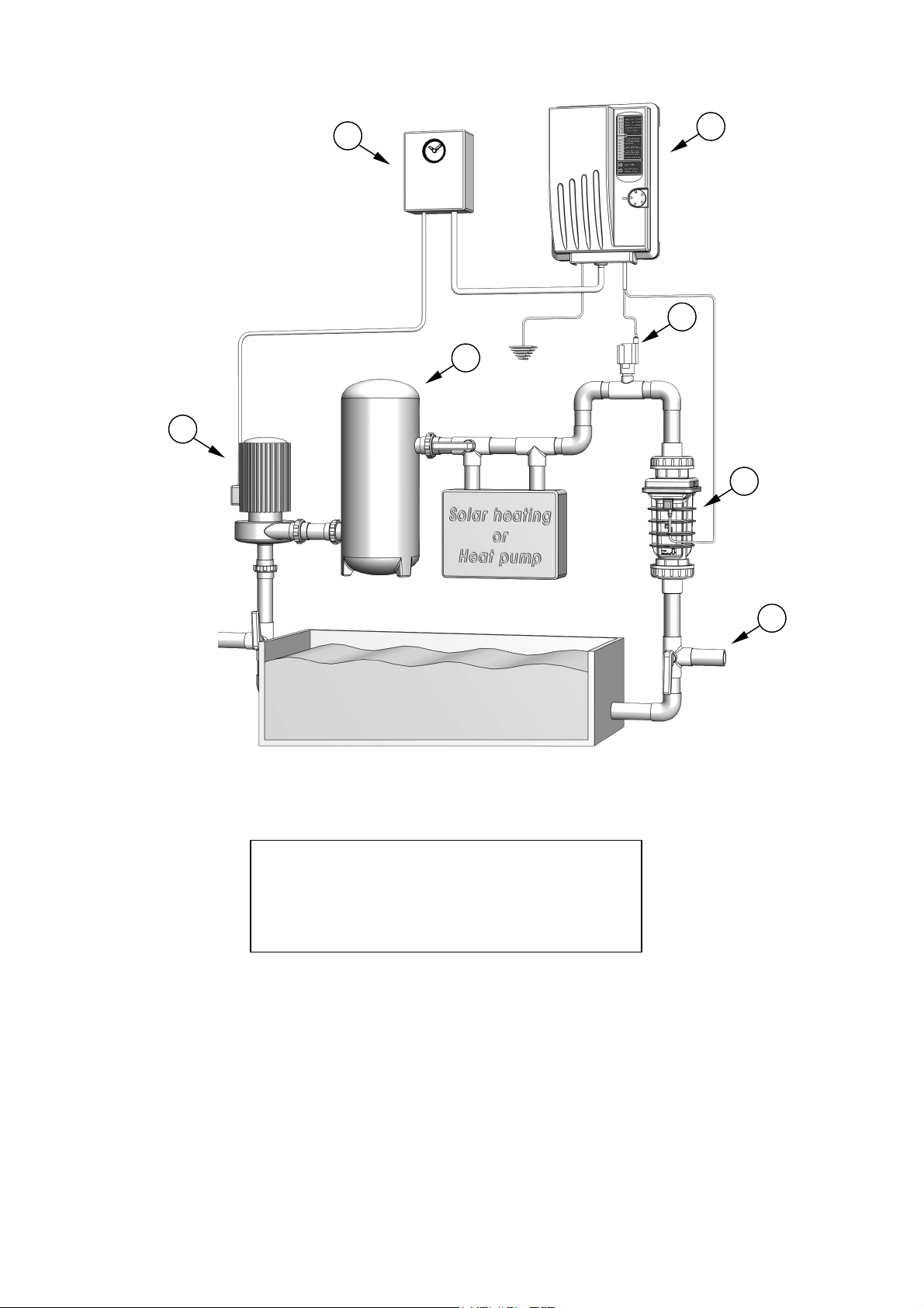
1. Control Box
2. Cell
3. Flow switch
4. Power / Timer
5. Filter
6. Pump
7. Spa line
The system comes in three sections, the Control Box, Cell and Flow Sensor. They are manufactured from the
latest corrosion resistant materials to give you years of trouble free use, and installing them in the most
sheltered position from sun and water will protect them from extreme weather conditions for years to come.
Safety Measures
1. Only operate the system with an approved flow sensor.
2. See safety measures and warnings on page 2 of this manual.
Additional Materials Required
1. PVC solvent cement and priming fluid 6. WD-40
2. Hacksaw or pipe cutters 7. Silicone Sealant (NO NOT USE silicone glue or
3. Screwdrivers petroleum jelly).
4. Drill 8. Pipe adaptors (i.e. reducer couplings) if
5. Teflon Tape (a.k.a. Plumber’s Tape) needed for systems with 1 ½ inch plumbing
4
Page 5
CONFIRM LAYOUT: Lay out equipment pieces to be sure there is enough pipe space
between the last piece of apparatus and the tees in the return line to fit the Flow Sensor and
the Cell. A Vertical installation may be used to save space (see diagrams above).
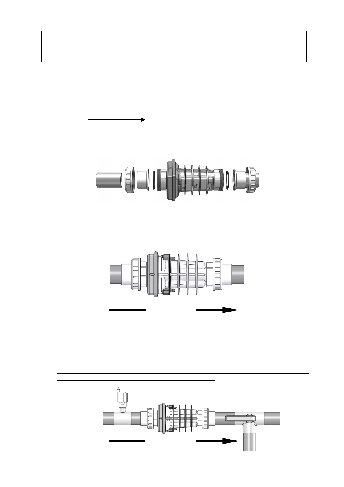
Install the Cell
1. The Cell and Flow Sensor must be installed downstream from the filter and heating devices but before
any tees in the return line. The Cell may be installed horizontally or vertically so long as the Cell is
pointed in the direction of flow and is installed immediately after the enclosed Flow Sensor (see
diagram above).
2. Approximately 15 inches (~380 mm) of available pipe length will be needed for horizontal installations
of the Flow Sensor and Cell. Vertical installations can be made to take less space.
3. On the pipe where the cell will be installed, mark two lines 11 3/4 inches (300mm) apart and cut out
using hacksaw or pipe cutters.
4. Unscrew and remove the barrel unions (i.e. barrel nuts and slip connections) from either end of the
Cell. Thread one of the barrel nuts over the pipe and glue its slip connection to the cut pipe.
5. Hold up the Cell with the second union to gauge the proper distance before threading the second nut
and gluing the second slip.
6. After the glue had sufficient drying time, place the Cell with the o-rings into the opening between the
two ends of the pipe and tighten the unions making sure that the Cell is installed with the arrow
pointing in the same direction as the flow (i.e. water should enter from the side with the blue cap).
Flow direction
Install the Flow Sensor
1. Install the Flow Sensor between the last piece of apparatus and the Cell (if installed after the Cell,
damage to the sensor may result). When possible, install on a horizontal pipe.
2. Mark two lines on the pipe 3 inches (~76 mm) apart and cut with a hacksaw or pipe cutters.
3. Clean and glue the “T” connector (included) to the pipe making sure that the threaded end with the
sensor is on the topside of the pipe.
4. Be sure the arrow on the top of the Flow Sensor is pointing in the direction of flow, and that no glue
touches the paddle inside the sensor as it may cause it to jam.
Flow direction
5
Page 6

Mount the Control Box
3
2
1. The Control Box must be mounted
vertically on a flat surface and a
minimum of 5 ft (1.5m) horizontal
distance (or more, if local codes
require) from the pool/spa.
2. Locate a position for your Control
Box within 10 ft (3½ meters) of
where the Cell will be installed and
within 2 ft of the power supply to
ensure enough wire is available.
3. Because the box acts as a heat sink
dispersing heat from inside the box,
do not block the four sides of the
Control Box. Do Not mount the
system inside a panel or tight
enclosed area.
1. Flow sensor connectors
2. Cell connectors
3. Bonding
4. Power Cord
4. Secure the hanging rack on the wall
using the enclosed screws and anchors. 1/4” (8mm)
drill bit should be used for the anchor holes.
5. Hang the Control Box on the mounted hanging rack.
4
1
6. Hardwire the power cable to the time clock as indicated in the instructions below. *Check the label on
the side of the Control Box for the proper voltage specification on your system (i.e. 120v or 240v).
7. Do not extend the cable leading to the cell. This decreases the system’s efficiency and will void
warranty coverage. Please contact the manufacturer for installations demanding a longer cell cable.
6
Page 7
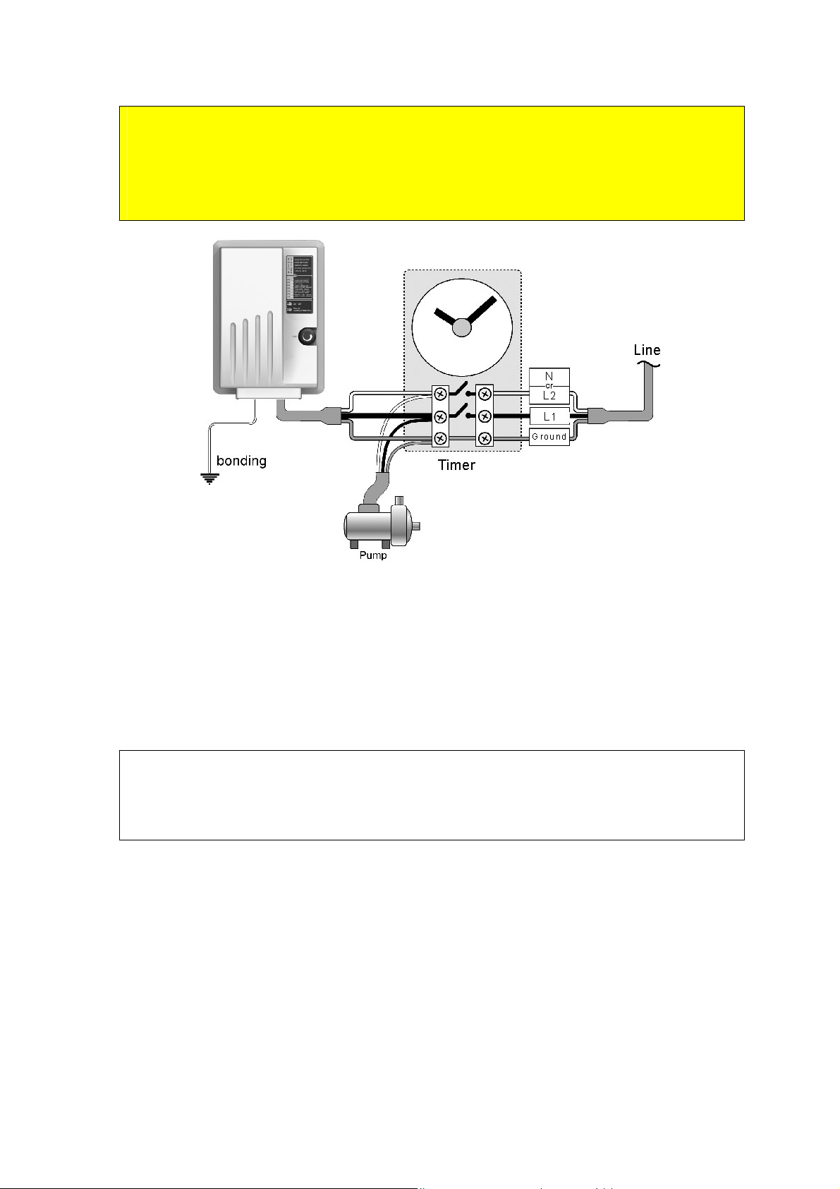
Wiring the Control Box to Standard Timer
CAUTION: Check whether your chlorine generator operates on 120 volts or 240 volts
(see label on the left side of the Control Box), and be sure to wire the system accordingly.
CAUTION: It is critical to wire the chlorine generator in such a way that it can only
operate when the pump is operating (i.e. load side). See instructions below for details.
1. Attach the green ground wire to the grounding lug or bar.
2. Connect the black Load wire from the chlorine generator to Load 1 of the time clock.
3. If wiring a 240 Volt generator, connect the third wire to Load 2 of the time clock. If wiring a 120 Volt
generator, connect the third wire to the Neutral lug or bar on the timer (see label on the left side of the
Control Box to confirm voltage).
4. Bonding is recommended and may be required by local code. The bonding lug is found on the bottom
of the Control Box.
Wiring the Control Box to Automated Systems
CAUTION: Check whether your chlorine generator operates on 120 volts or 240 volts
(see label on the left side of the Control Box), and be sure to wire the system accordingly.
CAUTION: It is critical to wire the chlorine generator in such a way that it can only
operate when the pump is operating (i.e. load side). See instructions below for details.
The Auto-Chlor Chlorine Generator can operate with virtually any automated control system as an auxiliary.
1. Attach the green ground wire to the grounding lug or bar.
2. Connect jumper wires from the Load side of the Circulation Pump Relay to the Line side of an
Auxiliary Relay as depicted in the relevant diagram below (based on the voltage used by the
pump and the chlorine generator) and in accordance with instructions of the automatic
controller manufacturer.
3. Connect the Auto-Chlor Chlorine Generator to the Load 1 & 2 connectors of the Auxiliary
Relay to control the generator’s operation.
4. Bonding is recommended and may be required by local code. The bonding lug is found on
the bottom of the Control Box.
5. Set the chlorine generator to 100% power, and program the Aux Relay to run the chlorine
generator as needed. (e.g. 100%, 50%, 25% of the time the pump is running).
7
Page 8
240Volt Circulation Pump With 240 Volt Chlorine Generator
120Volt Circulation Pump With 120 Volt Chlorine Generator
8
Page 9

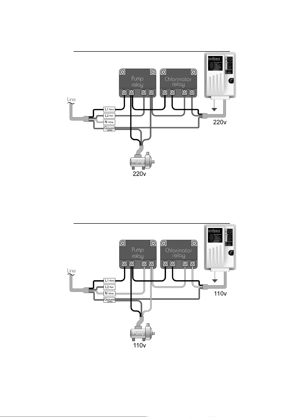
220Volt Circulation Pump With 220 Volt Chlorine Generator
120Volt Circulation Pump With 240 Volt Chlorine Generator
A 240 Volt Chlorine Generator may NOT be connected to a system with a 120 Volt circulation pump.
Wiring the Cell
Connect the two black wires from the Control Box to the two metal studs on the sides of the Cell and tighten
firmly with a screwdriver by hand. To avoid damage to the screws, DO NOT use a power screwdriver. Note
these wires are interchangeable. Push the plastic terminal covers up to cover the terminal connection until
they click into place. This will ensure a watertight connection.
Wiring the Flow Sensor
Find the two 18 AWG wires with the ¼” Quick connect terminals from the Cell cable and push them on their
respective connectors on the Flow Sensor. These wires are interchangeable.
9
Page 10

STARTUP
BEFORE ADDING THE SALT
o Balance the chemicals.
balance. Also, add 1 quart of metal remover and 1 quart of non-copper based algaecide to the pool,
according to the manufacturer’s instructions. This will ensure that the transition to the Auto-Chlor
system will be quick and trouble-free.
o Measure existing salt in your pool.
higher due to residual salt.
o New Pools: Wait 10-14 days, or longer if specified by the pool builder, for plaster to cure before
adding salt or operating the Auto-Chlor Chlorine Generator.
o Biguanide Pools: If installing on a pool using Biguanide sanitizers, all Biguanides must be removed
before system startup.
ADDING THE SALT
1. Determine how much salt is needed from the Salinity Demand Table on the following page. This table
is based on a salt concentration of 3500 ppm (approximately 1/3 of 1%). More may be added for
larger pools (e.g. 4000 ppm) and less for very small bodies of water.
2. Keep the pump on to circulate the water.
3. Distribute the determined amount of salt evenly around the pool. To avoid clogging the filter or
damaging the Control Box and pump, do not add salt through the skimmer or surge tank. Brushing
the bottom helps dissolve the salt.
4. The readout on the chlorine generator may fluctuate until the salt is fully dissolved.
UNACCEPTABLE SALTS
Do Not Use:
Iodized Salt
Salts with anti-caking agents of more than 1%
Rock salt because of the dirt mixed with the rock salt
Calcium chloride; it is not a salt.
See the titled “Understanding the Chemistry” for recommended water
Years of liquid chlorine use may cause the salt reading to be
10
Page 11

SALINITY DEMAND TABLE
(in lbs.)
Salt level before addition in PPM
Water volume in thousands of Galloons
Locate the current salt concentration at the top of the chart (e.g. 1000ppm). Then locate the size of your
pool on the left (e.g. 12,000 gallons). Run these figures down and across until they meet. That number is the
number of pounds of salt required for your pool.
4
6
8
10
12
14
16
18
20
22
24
26
28
30
32
34
36
38
40
42
44
46
48
50
0 500 1000 1500 2000 2500 3000 3500 4500
How much sat to add – in pounds
117 100
175 150 125 100 75 50 25 0 OK
234 200 167 133 100 67 33 0 OK
292 250 209 167 125 83 42 0 OK
350 300 250 200 150 100 50 0 OK
409 350 292 234 175 117 58 0 OK
467 400 334 267 200 133 67 0 OK
525 450 375 300 225 150 75 0 OK
584 500 417 334 250 167 83 0 OK
642 550 459 367 275 183 92 0 OK
701 600 500 400 300 200 100 0 OK
759 651 542 434 325 217 108 0 OK
817 701 584 467 350 234 117 0 OK
876 751 626 500 375 250 125 0 OK
934 801 667 534 400 267 133 0 OK
992 851 709 567 425 284 142 0 OK
1051 901 751 600 450 300 150 0 OK
1109 951 792 634 475 317 158 0 OK
1168 1001 834 667 500 334 167 0 OK
1226 1051 876 701 525 350 175 0 OK
1284 1101 917 734 550 367 183 0 OK
1343 1151 959 767 575 384 192 0 OK
1401 1201 1001 801 600 400 200 0 OK
1460 1251 1043 834 626 417 209 0 OK
83
67 50 33 17 0 OK
CALCULATING THE SIZE OF THE POOL
Rectangular Length x Width x Average Depth x 7.5 Length x Width x Average Depth x 1000
Round Diameter x Diameter x Average Depth x 5.9 Diameter x Diameter x Average Depth x 785
Oval Length x Width x Average Depth x 6.7 Length x Width x Average Depth x 893
Gallons
(dimensions are in feet)
Liters
(dimensions are in meters)
11
Page 12

OPERATING INSTRUCTIONS
BACKGROUND
Auto-Chlor is a chlorine generator for pool and/or spa sanitation. It is the workhorse of chlorine generators.
The system uses a very low concentration of salt, less than the concentration in a human teardrop, and
converts it into free chlorine that kills algae and bacteria in your pool. After killing the algae and bacteria, the
chlorine reverts back into sodium chloride. This process of purification continues, making the need to add
extra sanitizing chemicals to your pool virtually unnecessary.
The level of necessary chlorine in the pool is affected by a number of factors such as sunlight, bather load,
debris and water temperature, all of which increase sanitation and filtration demand.
Filtration
Proper filtration is critical for maintaining clean healthy water. Filtration increases clarity, and the Auto-Chlor
Chlorine Generator increases sanitation and oxidation. It is customarily required in the pool industry that all
the water in the pool pass through the filter at least one and a half (1 ½) times per day (~ 8 hours on most
pools). During very heavy usage, the filter and chlorine generator may be run continuously.
Inadequate filtration: Inadequate filtration reduces water clarity and makes more work for the generator.
Sanitation/Oxidation
The Auto-Chlor Chlorine Generator has little effect on pH, total alkalinity, or stabilizer levels. These must still
be monitored and adjusted to allow the system to have its greatest effect. If you use a good quality pool test
kit and follow the simple instructions outlined in this manual, your Auto-Chlor Chlorine Generator will help you
maintain a sparkling clean, trouble-free pool for many years with minimal effort. See the section titled
“Understanding the Chemistry” for more information.
BASIC OPERATION
The Auto-Chlor Chlorine Generator produces a pure form of chlorine to sanitize and oxidize your pool water.
The chlorine residual needs to be maintained at 1-3 ppm. This may be tested using a standard kit or by your
local pool store.
To generate more chlorine:
1. Turn the Control Knob to a higher setting as necessary, 10% to 100% chlorine production level. See
“Power Meter” in the next section for more details.
2. Ensure sufficient run time (at least 8 hours / 1 ½ turnovers) up to 24 hours per day.
3. Ensure salt level is correct and the Cell is clean (see “Salinity Indicator” in the next section).
4. Ensure proper water balance including pH and stabilizer levels (see “Understanding the Chemistry”
for recommended levels).
5. Point pool jets down and to the side.
* Summer weather increases demands for chlorine.
To decrease chlorine production:
1. Turn the Control Knob to a lower setting, 10% to 100% chlorine production level. (See “Power Meter”
in the next section)
2. Decrease run time as necessary.
Winterizing
Just like the pool plumbing, freezing may damage the system’s Cell and Flow Sensor. If severe or extended
periods of freezing temperatures are possible, drain all water from the pump, filter, and supply and return lines
before any freezing conditions occur.
Spring Start-up
DO NOT turn on the system until the pool water chemistry has been brought to required levels. See “Startup”
section for more information.
12
Page 13

5
3
2
CONTROLS
Control Knob (1) – The Control Knob is used to adjust chlorine production and to turn the unit on or off. To
increase chlorine production, turn the Control Knob up (clockwise). To decrease chlorine production, turn the
Control Knob down (counterclockwise). To turn the unit off, turn the Control Knob down (counterclockwise)
until it clicks.
NOTE: When changing the power setting, the system takes up to 1 minute to ramp up (i.e. soft start).
During this time, the green On/Off Light (4) will flash.
Power Meter (3) – The Power Meter lights indicate the system’s chlorine output (i.e. 10% to 100% production
rate). The higher lights indicate higher chlorine production.
A Solid Red Light (2) above the Power Meter (2) indicates
that the salt level in the pool is on the high side. This does
not harm the Chlorine Generator, but is provided as a
cautionary notice to the user not to add more salt to the
pool. Operation at very high levels (i.e. above 5500ppm)
is not recommended.
A Flashing Red Light (2) above the Power Meter (2)
indicates that the salt level is exceedingly high (i.e. above
7000ppm), and should be reduced immediately by draining
a significant amount of pool water and refilling the pool.
(Please check with your local pool professional prior to
draining the pool)
Flow Light (5) – This red light should NOT be illuminated
during normal operation. When first turning on the
circulation pump, the red Flow Light (5) may turn on and
off until the air is pushed out of the pump lines and
sufficient water flow is achieved. This is normal and
ensures that the generator automatically shuts off if the
pump fails to prime or a blockage occurs. See
Troubleshooting section if the red Flow Light (5) remains
on.
On/Off Light (4) – When the system is turned on and the
pump is operating, the On/Off Light (4) will illuminate
indicating that power is reaching the Control Box. The
color of the On/Off Light (4) indicates the following:
Solid Green – system is operational.
Solid Red – system is not powering the Cell.
Flashing Green – system is performing a “soft
start”; light will turn solid green within 1 minute.
Flashing Red/Green – reversing polarity; light will
turn solid green within 3 minutes.
Flashing Red – output current is below 0.5A;
check whether the cell cable connections are
completely on and tightened.
4
1
13
Page 14

r
t
Salinity Indicator – To check the salt level, turn the Control Knob clockwise to full power and
check the light reading.
100% reading indicates that the salt level is sufficient.
Return the Control Knob to the desired chlorine
production setting depending on the chlorine level in
your pool (10% to 100% production rate).
Red Light - above the Power Meter indicates that the
salt level in the pool is on the high side. This does not
harm the Chlorine Generator, but is provided as a
cautionary notice to the user not to add more salt to
the pool. Operation at very high levels (i.e. above
5500ppm) is not recommended. Slowly turn down the
Control Knob until the desired Power Meter light
illuminates (i.e. desired chlorine production level).
If Power Meter lights go up & down quickly: The salt
level is high. Slowly turn down the Control Knob
(counterclockwise) until the desired Power Meter light
illuminates. If the lights continue to go up and down
after the Control Knob was turned down, the salt level
is exceedingly high, and should be reduced
immediately by draining a significant amount of pool
water and refilling the pool.
local pool professional prior to draining the pool).
Readings between 10% and 80% indicate a low sal
level, except when the Cell is worn or calcified. Check
the Cell to ensure the blades are in good condition and
not coated with calcium buildup. Cleaning the Cell is
recommended if it is calcified or if the readout seems
questionable. Before adding salt, it is advisable to
have the salt level professionally checked.
(Please check with you
14
Page 15

MAINTENANCE
Maintaining your Auto-Chlor Chlorine Generator requires minimal work but will maximize the
performance and life of the system.
POOL WATER TESTING: Pool water should be tested weekly.
Cell Maintenance
Our clear Cell allows for easy regular inspections for calcium build up. Visually check the Cell periodically,
and clean it as necessary (1 to 2 times per year). Advanced self-cleaning technologies, including reverse
polarization and IBT™ help the cell stay cleaner than other self-cleaning cells.
Cell Cleaning
Do Not use metal or other hard objects to clean the cell as this
could scratch the precious coating on the plates and void the
warranty.
CAUTION: Always add acid to water, NOT water to acid
Diluted muriatic acid solution = 10 parts water to 1 part
acid
Note: Follow the instructions of the acid manufacturer.
Cleaning With Optional Cleaning Cap:
1. Remove the cell from the line by undoing the electrical connections from the Cell and the barrel
unions from the cell ends.
2. Remove the black o-rings on the ends of the Cell.
3. Attach the Cell Cleaning Cap to one end of cell.
4. Pour into Cell, either undiluted white distilled vinegar, or a solution of diluted muriatic acid (10 parts
water to 1 part muriatic acid).
5. Wait for foaming to stop (5-10 minutes when using muriatic acid, vinegar takes longer).
6. If muriatic acid was used, safely dispose of it by pouring it into your pool.
7. Rinse cell with water hose.
8. Put the O-ring back in place and re-install the Cell in the line.
9. Reconnect the electrical wires, being sure to tighten the screws on the electrical wires firmly.
15
Page 16

Cleaning Without Optional Cleaning Cap:
1. Remove the cell from the line by undoing the electrical
connections from the Cell and the barrel unions from the cell ends.
2. Remove the black o-rings on the ends of the Cell.
3. Soak entire cell either in undiluted white distilled vinegar or in a
solution of diluted muriatic acid (10 parts water to 1 part muriatic
acid).
4. Wait for foaming to stop (5-10 minutes when using muriatic acid;
vinegar takes longer)
5. If muriatic acid was used, safely dispose of it by pouring it into
your pool.
6. Rinse cell with water hose.
7. Put the O-ring back in place and re-install the Cell in the line.
8. Reconnect the electrical wires, being sure to tighten the screws on
the electrical wires firmly.
Optional
1. Lubricating the o-rings with a rubber lubricant (e.g. silicone) helps improve the seal of the fittings, but
be sure not to use silicone glue, petroleum jelly (such as Vaseline), or other agents that could
deteriorate the o-rings.
2. Smear the two electrical connections on the outside of the cell with electrical lubricant.
16
Page 17

UNDERSTANDING THE CHEMISTRY
Below is a table showing the recommended balance levels followed by a more detailed explanation of the
factors affecting water chemistry. Maintaining these levels will prevent corrosion and scaling and will ensure
maximum enjoyment of the pool. You should test your water periodically. If the water chemistry needs
adjustment, your authorized dealer or most pool stores can supply you with the appropriate chemicals and
procedures. We recommend you either take a copy of the Water Balance Table to the pool store or notify the
pool store that you are using a salt chlorine generator.
FACTORS IDEAL LEVELS
Salt 3000 to 4000 ppm
Free Chlorine 1 to 3 ppm
PH 7.2 to 7.6
Total Alkalinity 110 to 180 ppm (Depending on the Saturation Index)
Stabilizer (Cyanuric Acid) 40-80 ppm
Nitrates 0 ppm
Metals 0 ppm
Phosphates O ppm
Calcium Hardness Determine level for individual pool surface
Saturation Index -0.3 to 0.3 (0 is ideal)
Salt
Salt is the power source of the Auto-Chlor Chlorine Generator. To ensure maximum benefits with the use of
the system, the ideal salt level is 4000 ppm (parts per million). A low concentration of salt can hinder the
generator’s effectiveness. A concentration of salt above 5500 ppm may cause corrosion damage to the pool
fixtures. See the Adding Salt section for more information.
Total Dissolved Solids (TDS) are different from the salt level of the pool, although TDS levels rise by adding
salt to pool water. This does not harm the pool water chemistry or clarity, but the pool water professional that
is testing for TDS must be aware that salt has been added for the chlorine generator system. The pool
professional doing the TDS test will get the accurate TDS level by subtracting the salinity level.
Free Chlorine v. Combined Chlorine: The unpleasant smells and side effects often associated with chlorine
are actually caused by combined chlorine (i.e. chloramines). Combined chlorine is a chlorine molecule that
attacked a noxious particle in the water but has been unable to destroy that noxious particle. This chlorine
particle remains attached to the noxious particle until one of the two is burned off; hence the term “combined
chlorine” (a.k.a. chloramines). To burn off the noxious particle and free up the chlorine again, pool owners
have had to shock the pool periodically, but with the Auto-Chlor Chlorine Generator, the noxious particles are
burned off within the generator’s Cell and the combined chlorine is continuously converted back to free
chlorine.
The free chlorine level in the pool should be maintained at 1 to 3 ppm. This level of free chlorine is
comfortable to swim in with no unpleasant smells, and it maintains proper sanitizing power.
PH is a measure of how acidic or basic a solution is. A scale of 0 to 14 is used to measure pH. Pure water
has a pH of 7 (neutral), acid solutions have a pH of less than 7, and basic (alkali) solutions have a pH of more
than 7. The recommended range is 7.2 to 7.8; chlorine is more effective within this range and the water is
most comfortable for bathers. Water with very high pH levels can cause scaling in the pool, on the walls and in
pipes. Low pH levels cause the water to be aggressive to the pool walls, equipment, and bathers.
To lower pH, add muriatic acid or dry acid, and to raise pH, add soda ash (sodium carbonate). Be sure to
read and follow the respective manufacturer’s instructions.
Total Alkalinity mitigates changes in pH. It is often referred to as the “big brother of pH.” Keeping proper
levels of total alkalinity will help reduce unwanted fluctuations in pH levels. Total alkalinity is also used to
offset high or low levels of calcium hardness (see Saturation Index below). Add muriatic acid or dry acid to
17
Page 18

lower total alkalinity and add baking soda (sodium bicarbonate) to raise total alkalinity. Be sure to read and
follow the respective manufacturer’s instructions.
Stabilizer (cyanuric acid) is necessary in most outdoor pools to maintain appropriate levels of chlorine.
Chlorine stabilizer helps give an appropriate residual chlorine reading of the pool water. Without stabilizer, UV
radiation from the sun destroys most chlorine within 2 hours, but excessive amounts of stabilizer can decrease
the effectiveness of chlorine. Chlorine stabilizer should be maintained at 40-80 ppm to offset the harmful
effect of the sun while maintaining the effectiveness of the chlorine.
Nitrates and Phosphates, generally associated with fertilizer thrown on nearby grass, can put very high
demands on chlorine; most often nitrates and phosphates will bring the chlorine level down to zero (0). You
can have your water tested for nitrates and phosphates by the local pool professional. No nitrates or
phosphates should be in your pool.
pool professional. To reduce Nitrate levels, the pool must be partially or fully drained. (Please check with your
local pool professional prior to draining the pool)
Metals (certain metals) can cause loss of chlorine and can stain your pool. If a water test reveals the
presence of metals, refer to your local pool professional for recommended methods of removal.
New Pool Water in recently filled or newly refinished pools may contain undesirable matter. The ability of the
Auto-Chlor Chlorine Generator to purify your pool could be hindered by this matter so it is best to balance the
pool chemicals first.
Calcium Hardness, like pH and alkalinity, affects the water’s tendency to be aggressive or scale forming.
Lower levels of calcium hardness improve the chlorine generator’s performance and provide softer silkier
water for the swimmers.
Saturation Index determines whether the pool water is balanced, aggressive, or scale forming by
comprehensively taking into account all the relevant factors, including pH level, alkalinity level, calcium
hardness, and temperature. These factors should be tested periodically then plugged into the worksheet on
the following page to verify the proper balance of the pool and make adjustments as necessary.
To reduce phosphate levels, use a phosphate remover from your local
18
Page 19

SATURATION INDEX
Test the water for pH, Alkalinity, Calcium Hardness, and Temperature, then follow the simple steps below:
1. Write your pool’s pH level here: pH: ________
2. Find your Alkalinity level in the chart below, and write the
corresponding Alkalinity Factor here: Alkalinity Factor: ________
Pool Alkalinity 5 25 50 75 100 150 200 300 400
Factor 0.7 1.4 1.7 1.9 2.0 2.2 2.3 2.5 2.6
3. Find your Calcium level in the chart below, and write the
corresponding Calcium Factor here: Calcium Factor: ________
Pool Calcium
(CaCO
Factor 0.3 1.0 1.3 1.5 1.6 1.8 1.9 2.1 2.2
4. Find your pool temperature in the chart below, and write the
corresponding Temperature Factor here: Temperature Factor: ________
Pool Temp 32 37 46 53 60 66 76 84 94 105
Factor 0.0 0.1 0.2 0.3 0.4 0.5 0.6 0.7 0.8 0.9
5. Add the results from steps 1 through 4 above and write the result here: Total of above: ________
)
3
5 25 50 75 100 150 200 300 400
- 12.2
6. Subtract 12.2 from step 5 and write the result here: Saturation Index =
If the Saturation Index above is between –0.3 and +0.3, the water is well balanced.
If the Index is more than 0.3, the water will tend to cause scaling or get cloudy. Alkalinity and pH
should be reduced accordingly, but maintained within recommended levels.
If the Index is less than -0.3, the water will tend to be aggressive toward the pool surface, equipment,
and bathers. Alkalinity and pH should be increased accordingly, but maintained within recommended
levels.
19
____
Page 20

TROUBLESHOOTING
Note: evaluating the possible causes for each problem from top to bottom (first to last) will avoid extra labor.
PROBLEM
1. Chlorine
Level Low
2. Green Pool
3. On/Off Light
is OFF: No
power
4. On/Off Light
is Solid Green
5. Red Flow
Light is Off
6. Flow Light is
Turning On
and Off
7. Flow Light is
Solid Red
8. Power Meter
lights do not reach
100%
POSSIBLE CAUSES
System is turned off. Turn Control Knob to the desired setting.
Control Knob is set too low in
relation to chlorination demand
(e.g. higher number of bathers,
warmer weather, increased debris
in pool).
Low Salinity
Pump operation time too short
Low Stabilizer (Cyanuric Acid)
Chemical Imbalance
Chlorine level too low. See “Chlorine Level Low” above.
System is turned off.
Main fuse blew.
Breaker jumped Check the breaker leading to the pool control.
Power wires cut,
disconnected, or incorrectly wired.
Other malfunction in Control
Box.
System is on. This is
normal.
This is normal.
This is normal at initial start-
up or if air bubbles are in pipes.
Insufficient water flow from
pump to Flow Sensor and Cell.
Obstruction or scale
buildup in Cell.
Flow Sensor was not
installed in the correct
direction.
Flow Sensor is not fully
threaded into the “T”
connector.
Cut wires or insufficient
wire connections.
Control Knob set too low
Dirty Cell, Loose Connection,
or Salinity Low.
WHAT TO DO
Turn Control Knob higher (clockwise) and/or
increase pump operation time.
Check the salinity level.
(See “Salinity Indicator” section).
Run pump at least 8 hours per day (1.5
turnovers of all the pool water).
Check water chemistry; stabilizer should be
between 40-80 ppm. If low, add stabilizer (See
“Understanding the Chemistry”).
Check other chemistry and balance
chemicals. (See “Understanding the Chemistry”).
Turn Control Knob clockwise to the desired
setting.
Check main fuse on bottom of Control Box
and replace if necessary with a 6.3 Amp 250VAC
6x32mm Slow Blow fuse. One extra fuse is
supplied on the bottom-side of the Control Box
cover.
Check for correct wiring.
Contact warranty hotline.
Wait a few minutes for air to clear. If
continuous, see troubleshooting section “Flow
Light is Solid Red” below.
This is normal for a few minutes at initial
startup or if air is in the lines.
Clean filters and strainers.
Check for closed valves, faulty pump, etc.
Clean Cell according to instruction
manual. (See “Maintenance” section)
Turn Flow Sensor so arrow faces
direction of water flow.
Fully thread the Flow Sensor into the T
connector being careful not to damage the
wires or sensors.
Check the connection to ensure proper
wire contact.
Turn Control Knob higher (clockwise).
If the red light above the Power Meter
illuminates or if the lights go up and down,
see
Troubleshooting Section “Salinity High” below.
See Troubleshooting Section “Salinity Low”
below.
20
Page 21

TROUBLESHOOTING
Note: evaluating the possible causes for each problem from top to bottom (first to last) will avoid extra labor.
PROBLEM
9. Salinity Low
10. Salinity
High
11. RED light at
the top of the
Power Meter is lit
12. Lights go up &
down quickly
POSSIBLE CAUSES
Dirty Cell
Loose connection with the
Cell’s connection pegs.
Not enough salt due to
heavy rain, initial
miscalculation, etc.
Worn Cell
Salinity High. Enough salt
has been added causing the red
light above the power meter to
light.
Salinity is very high. Too
much salt has been added causing
the Power Meter Lights to go up
quickly, and then shut down.
Salinity far too high. Way too
much salt has been added causing
the Power Meter to completely
shut down.
Salinity high
Salinity is very high.
WHAT TO DO
Check the Cell to ensure the blades are
in good condition and not coated with calcium
buildup. Cleaning the Cell is recommended if
it is calcified or if the readout seems
questionable. (See “Cell Cleaning” under the
“Maintenance” section).
Ensure the connectors are pushed
completely over the pegs and tighten
connections with a screwdriver.
Add salt into the pool. See the “Adding
The Salt” section for more information.
It is also recommended to periodically
test the salt level by a professional and adjust
according to the “Salinity Demand Table” in
this manual.
If none of the above resolutions worked,
the cell may be worn out.
This does no harm to the Natural Generator,
but simply indicates that the salt level is on the
high side for your information. Slowly turn down
the Control Knob (counterclockwise) until the
desired Power Meter light illuminates.
It is also recommended to periodically test the
salt level by a professional. If above 5500 ppm, it
is recommended to drain part of the pool water
and refill with fresh water. (Please check with your
local pool professional prior to draining the pool)
The salt level is very high. Drain part of the
water and refill the pool to bring the salinity down.
It is also recommended to periodically test the
salt level by a professional. If above 5500 ppm, it
is recommended to drain part of the pool water
and refill with fresh water. (Please check with your
local pool professional prior to draining the pool)
The salt level is exceedingly high. Drain part
of the water and refill the pool to bring the salinity
down.
It is also recommended to periodically test the
salt level by a professional. If above 5500 ppm, it
is recommended to drain part of the pool water
and refill with fresh water. (Please check with your
local pool professional prior to draining the pool)
See Troubleshooting Section “Salinity High”
above.
Drain part of the water and refill the pool to
bring the salinity down. See Troubleshooting
Section “Salinity High” above for more information.
It is also recommended to periodically test the
salt level by a professional. If above 5500 ppm, it
is recommended to drain part of the pool water
and refill with fresh water. (Please check with your
local pool professional prior to draining the pool)
21
Page 22

13. Power Meter
not responding,
but On/Off light is
on
build-up inside
Cell
15. White flakes in
the water
16. Cloudy water
17. Colored Water
18. Algae
Control Knob set too low Turn Control Knob up (clockwise).
Improper salt level. The
system automatically shuts down
the Power Meter when the salt
level is extremely low or extremely
high.
Standard occurrence that
needs to be cleaned approximately
twice/year.
Chemical imbalance.
Normal occurrence when Cell
cleans itself.
May be due to chemical
imbalance or low water flow
Metals in the fill water may
have been oxidized.
Algae may be trying to form.
May be due to low chlorine
levels or a chemical imbalance
Check salt level using a test kit or your local
pool professional. The salt level is likely at an
extreme level. Adjust accordingly.
Clean Cell as instructed in the “Maintenance”
section. 14. Scale
Balance chemicals. (Focus mostly on the
“Saturation Index” in the section titled
“Understanding the Chemistry”).
Keeping the water well balanced reduces this
occurrence. (Focus mostly on the “Saturation
Index” in the section titled “Understanding the
Chemistry”).
Make sure your filtration system is working
properly (i.e. clean filter and/or skimmer).
Make sure circulation time is adequate –
increase pump time if not.
Make sure total alkalinity is balanced.
Shock the water to eliminate build up of any
organic matter.
Make sure pool has free chlorine reading of
1.0 to 3.0 ppm
Check with dealer for more information
Have dealer test the pool water. If high in
metals use a Metal out or Sequestering product at
start-up only.
Increase circulation time if needed and clean
the filter.
Check with your dealer for more information.
Have your water tested for chemical balance
including pH, phosphates, and nitrates.
Use a nonmetallic (polyquat) algaecide per
the directions on the bottle and brush the sides of
the pool often.
Clean the filter and shock the pool with
chlorine daily until water clarity returns.
Check with your dealer for more information.
Our contact information is found on the front cover of this manual. For additional information, please visit our website. For
warranty service, questions, or comments, please contact us directly. Technicians are available from 9:00 AM to 4:00 PM
Eastern Standard Time, Monday through Friday. Please have the following information ready:
1. Model and Serial #
2. Date of installation
3. Installing company or dealer
4. Current salt level and chemical levels
5. Proof of Purchase (bill of sale, cancelled check, or some other appropriate payment record)
22
Page 23

Ten (10) Year Limited Warranty
Models: AC-4000 and AC-6000
WARRANTY
This warranty applies to all AC-4000 and AC-6000 chlorine generators and their factory-supplied components (the “System”) when
purchased from an authorized dealer and used for residential swimming pools or spas. Aqua Comfort Technologies, LLC (“ACT”)
warrants the System to be free from defects in materials and workmanship in the manufacturing process for a period of ten (10) years
from the purchase date, when properly installed and operated in accordance with the relevant manuals. For three (3) years after the
System’s original purchase date, should the System exhibit a manufacturing defect, ACT will install comparable replacement parts
without charge for parts or labor. For the subsequent 7 years, if a part with a manufacturing defect is delivered freight prepaid to
ACT, a comparable replacement part will be sent back for a charge of 60% of the latest list price plus the cost of shipping.
EXCEPTIONS & LIABILITY LIMITATIONS
This warranty is not transferable. Labor coverage is applicable only for installations within a 50-mile radius of an authorized dealer.
ACT and their suppliers, dealers, and distributors SHALL NOT BE LIABLE FOR INCIDENTAL OR CONSEQUENTIAL DAMAGES;
DAMAGE OF ANY SORT OR NATURE RESULTING FROM ABUSE, MISUSE, NEGLIGENCE, LIGHTNING, ABNORMAL WEATHER
CONDITIONS, OR ACT OF GOD; OR DAMAGE CAUSED BY IMPROPER OR UNAUTHORIZED INSTALLATION OR REPAIR. This
warranty applies only to components supplied by the factory and only where such components have been installed and maintained in
compliance with the respective installation and operation manuals and instructions and applicable ordinances and codes. In no event
shall the liability exceed the purchase price of the product. THE CONSUMER SHALL BE LIABLE AT STANDARD RATES FOR ANY
SERVICE VISIT WHERE NO MANUFACTURING DEFECT WAS PRESENT AND FOR ALL SERVICE VISITS REQUESTED AFTER
THE THIRD YEAR FOLLOWING THE ORIGINAL PURCHASE DATE.
PROOF OF PURCHASE
The consumer is responsible for establishing the original purchase date and the purchaser’s identity for warranty purposes. We
recommend that a bill of sale, canceled check, or some other appropriate payment record be kept for that purpose.
The express warranty above constitutes the sole and complete warranty and takes precedence over all other warranties, whether
expressed or implied, including a warranty for fitness for a particular purpose. No sales representative, dealer, distributor, or other
person is authorized to give any warranty on behalf of ACT.
OWNER’S REGISTRATION FORM 10-YEAR LIMITED WARRANTY
Owner’s Name__________________________________________Signature____________________________________
Street Address____________________________________________________City_______________________________
State_________ Zip_________________ Phone # _______________________Date of Purchase__
Authorized Dealer _____________________________ Sales Rep____________________City______________________
State_________ Zip________________ Unit Serial # ______________________
How did you hear about our product? (Please check all that apply)
___ Pool Store Employees ___ Pool Builder ___ Pool Service ___ Direct Mail ___ In-Store Display___ Friend/Relative
___ Magazine ___Newspaper ___ Radio ___ TV ___ Catalog ___ Other:_______________________ ________
Comments: ________________________________________________________________________________________
__________________________________________________________________________________ _______________
* If more space is necessary, please utilize the back of this form.
IN ORDER TO ACTIVATE YOUR WARRANTY Aqua Comfort Technologies, LLC
PLEASE RETURN THIS PORTION TO: P.O. Box 1520 y Sykesville, MD 21784-1520
__/______/ _
23
Page 24

RETURN ADDRESS
______________________________
______________________________
______________________________
AQUA COMFORT TECHNOLOGIES, LLC
ATTN: WARRANTY DEPT. (MBP)
P.O. BOX 1520
SYKESVILLE, MD 21784-1520
24
 Loading...