

Page 1
2300 Controller Quick Start Guide, Rev. 1.2 Page 1
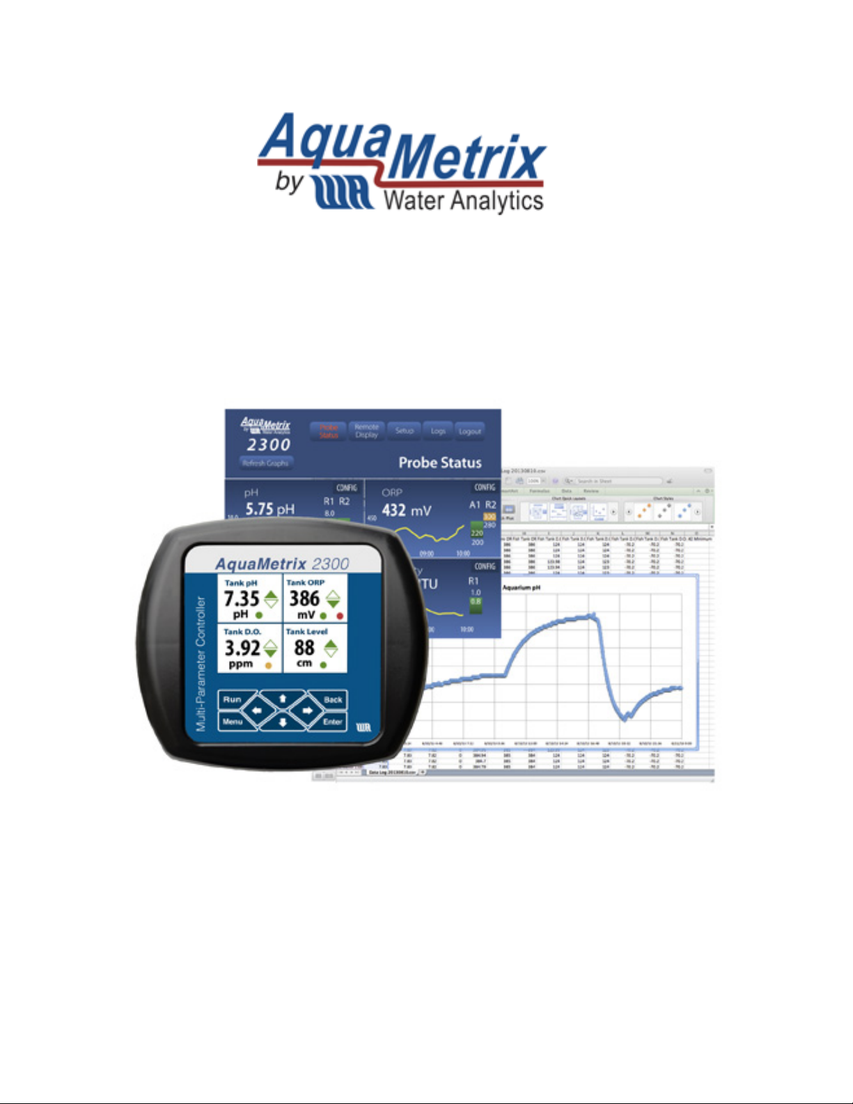
AquaMetrix 2300
Multi-Input Controller
Quick Start Guide
Page 2
2300 Controller Quick Start Guide Page 2
Welcome to the Easy Way of Controlling Your Probes
This guide augments the operation manual, showing you how to mount and configure the standard
2300 Controller. Information on using the controller with additional or non-standard I/O cards can be
found in the operation manual, which is available for download on www.Aquametrix.com.
This Quick Start Guide is written for software-preconfigured 2300’s to allow wiring and start of
basic operation of the controller without hooking up to a network first.
1. Installation
WARNING: If this equipment is used in a manner not specified by the manufacturer as per the Users
Manual and this Quick Start Guide, the protection provided by the equipment may be impaired.
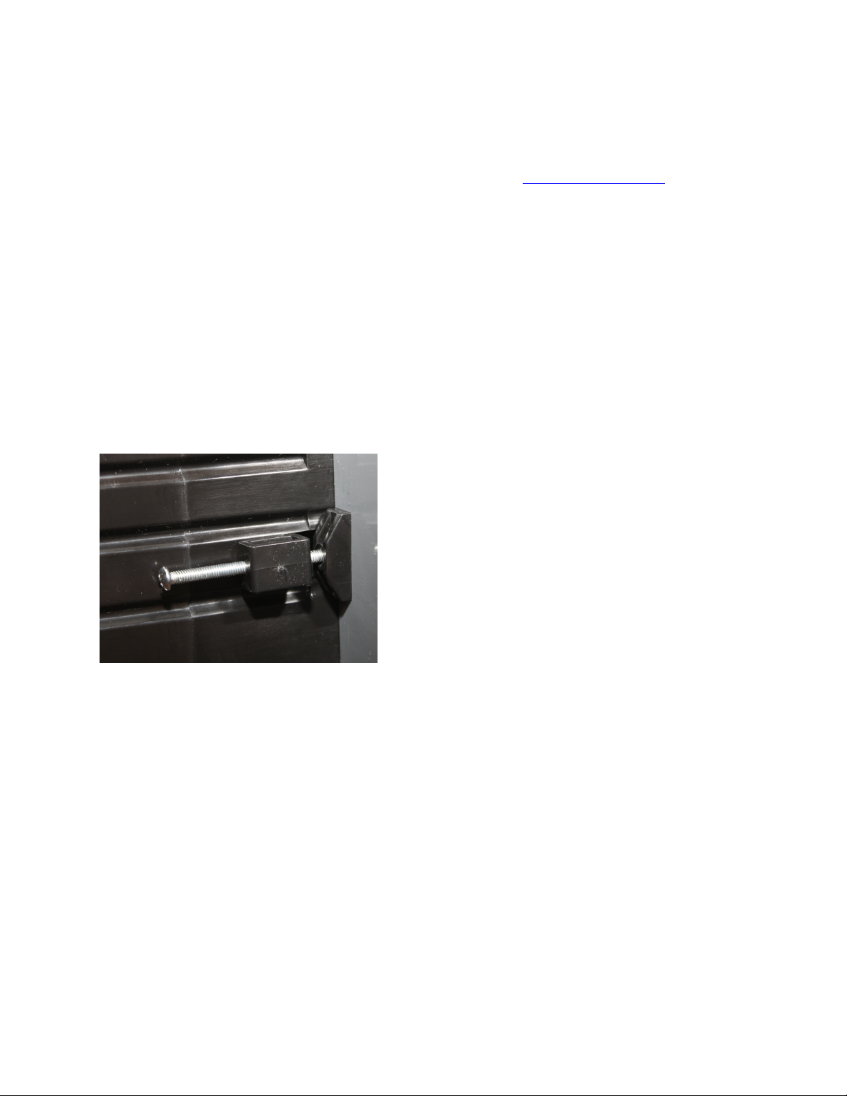
1.1. Panel Mounting
Mount the 2300 Controller through the front panel, with the gasket on the outside of the mounting
panel. Hook the sliding mounting blocks on each side of the back of the 2300 Controller enclosure and
tighten the setscrews against the mounting panel with a torque of 4 in-lb as shown in Error!
Reference source not found..
Figure 1 - Mounting hardware attached to panel
with 4 in-lb of torque
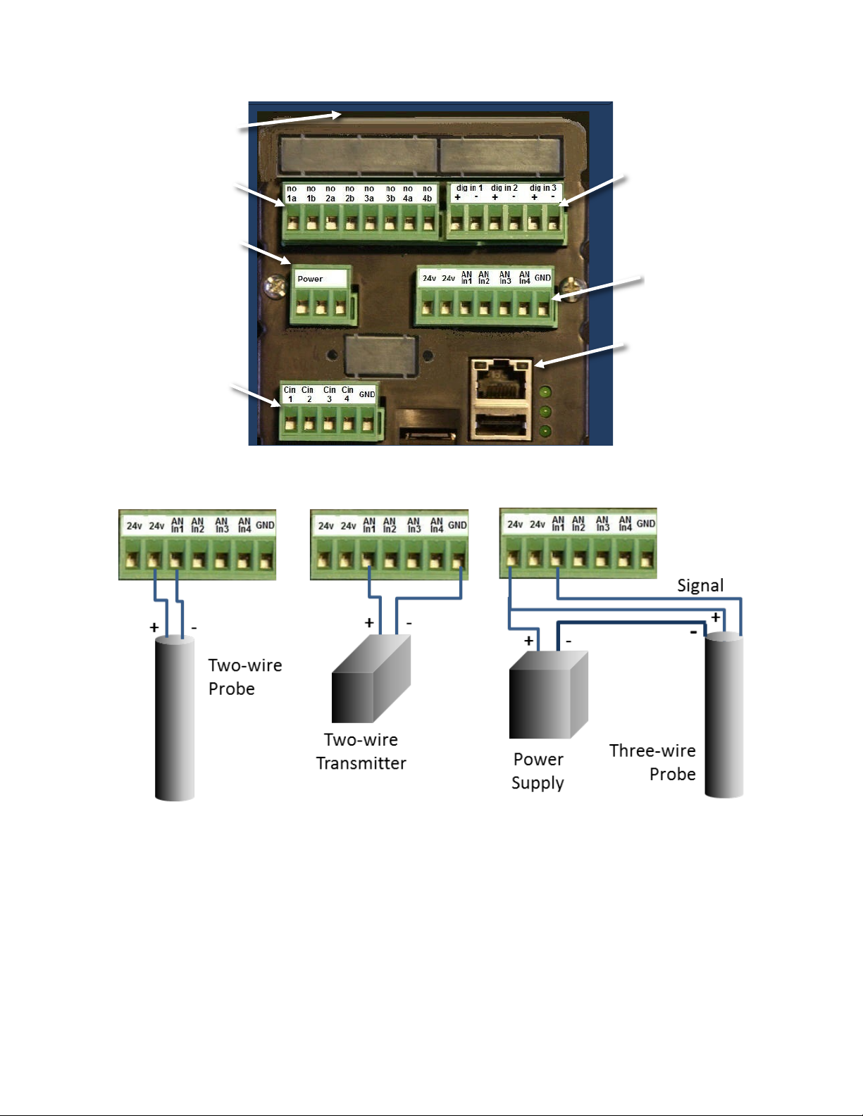
1.2. Power, Probe, and Network Cabling
A picture of the rear of the 2300 is shown below in Figure 2. We recommend removing the Molex
connectors and connecting wires to them and then attaching the connectors to the unit.
Connect the:
• Power cord
• CAT-5 Ethernet cable—to be used later as described in Section 2.
• Probe wires. 2-wire 4-20 mA cables connect to the analog connector. Pulse inputs connect to
the digital inputs.
Probe wiring depends on the type and manufacturer of the probe, and instructions can be found with
each probe. We show examples of the different wiring diagrams in Figure 3 that may be called for by
your analog (4-20 mA) probes, but please look up your individual probe directions. Connections for
flow meters, which output a pulse frequency, such as paddle wheels or magmeters, use the pulse
input connector (“dig in 1” et al).
Page 3
2300 Controller Quick Start Guide Page 3
Figure 2 - 2300 Controller back panel
Figure 3 - Possible analog probe wiring diagrams. There are other possible three-wire probe
setups, so please refer to your specific probe’s instructions for proper hook up.
1.3. Powering Up the 2300
With the probes connected, power up the 2300. If the controller is operating properly, the green LED's
on the back panel indicate proper operation. From top to bottom:
1. The top most LED is the Fault light it should be slowly blinking.
2. The middle LED is the System Operating light and it should be quickly blinking.
3. The bottom LED is the Power On light and it should be on and steady.
Ethernet Connection
Power 120-220 VAC
Pulse Input (digital)
Connector
Relay Connector
Contacts Connector
Analog (4-
20mA) Input
Connector
L N G
Page 4
2300 Controller Quick Start Guide Page 4
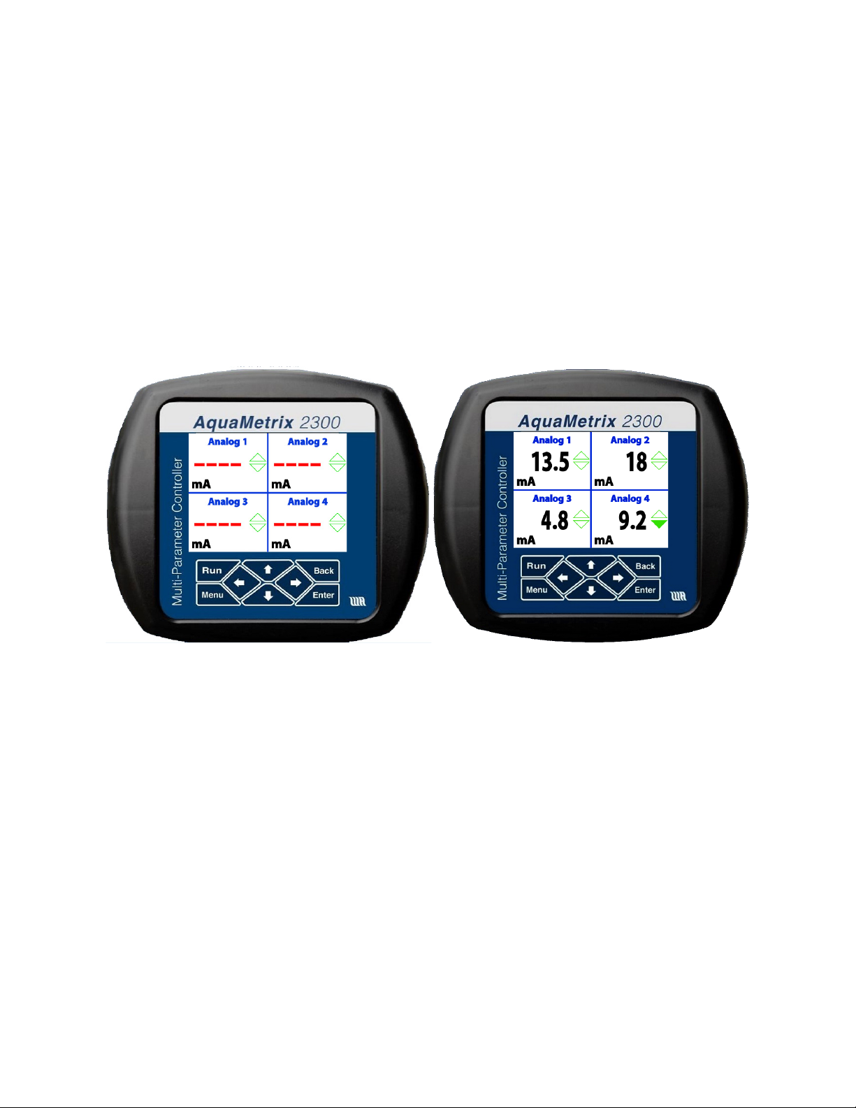
The Run screen should appear and display 4 panes. It will show the actual mA reading of the four
analog probes (see Figure 4). Dashes (----) indicate that a probe is either not connected or it is out of
range. Note that the preconfigured software only shows the actual current being read by the 2300. In
order to have probe outputs expressed in the appropriate units (e.g. pH, mV, µS/cm, etc.) you need to
carry out set-up over a network using a web browser. See Section 1.5 or 1.6 of this guide for network
setup, and Section 2 for configuring the 2300 over the network. The main purpose of this initial screen
showing the raw current outputs of the connected probes is simply to reassure you that that
controller is running properly.
To navigate the front panel screens, use the front-panel buttons as follows:
• RUN brings up the quad screen from anywhere
• MENU brings up the front panel menu
• BACK returns the user to the previous screen.
Figure 4 - The RUN screen showing four analog probe inputs. On the left is a display showing
that no probes have been connected. On the right, four analog probes have been connected.
The 2300 is software-preconfigured for six probes, allowing the user to wire up probes and start
operation prior to network hookup. Analog 1 is set up to the analog 1 input on the back of the unit.
The first 4 software channels are shown on the RUN quad screen. If you have more than 4 sensors
connected, press the down arrow to see channels 3 through 6. Channels 5 and 6 are set up as flows
using the pulse inputs 1 and 2 (see Figure 2). The 2300 can be easily reconfigured via a network,
including changing the names, units, order of probes, and just about everything else you can think of.
Use the right arrow on a quad screen to see detailed screens for each channel, addressable by the up
or down arrows. Pressing ENTER on a detailed screen brings up a configuration screen for that
channel. Examples of each are shown below in Figure 5. Press BACK or RUN to move up a level or two
in the front display.
Page 5

2300 Controller Quick Start Guide Page 5
Figure 5 - The channel Detail screen and Configure screen for Channel 1
The detailed screen lists alarm and relay set points, last calibration date, and will flash when the
channel is in alarm mode. The configure screen allows resetting of the alarm and relay set points,
alarm acknowledgement, and zeroing of the totalizer and dispenser functions and other channelspecific functions.
1.4. Front Panel Menu Options
The front panel menu choices are limited as the 2300 is designed to be configured and operated over
a network in a browser. However, there are several key functions available to the user on the front
panel. These include calibration and setting up the network. The main menu is shown in Figure 6.
Figure 6 - Main Menu screen
Use the up or down arrow keys to target an item, and the Enter key to select it. If there are more than
4 choices available, the bottom (or top) corner on the right will be notched.
The menu options are listed in outline form below in Table 1. You may calibrate your probes from the
front panel, but remember that full functionality of the unit is only available via the Ethernet cable
from a network, or browser on a computer, tablet, or phone. Customize your unit via a network to
display proper units, names of probes, and to configure alarms, relays, and notifications.
Page 6

2300 Controller Quick Start Guide Page 6
Table 2 – Front Panel Menu Structure
Menu Item
Description
View System Info
Single screen showing unit Name, IP Address, etc.
Calibrate/Disable Probe
Enable, disable, or calibrate probes
Select Probe
Any defined probe, including virtual probes
Select Action
Calibration is 2-point calibration for the analog inputs, K
Factor scaling for the digital inputs.
Backup/Restore
Saves or Restores a configuration file onto/from the external
micro-SD card, including probe setups and calibrations, alarm
and relay set points, and system configuration.
Reboot System
Closes all open files and restarts system.
Prepare for System Shutdown
Closes all open files.
Advanced Menu
Calibrate Analog In
Password protected for factory calibration only
View Precision
Input
Not Used
Network Setup
Changes from DCHP to Static IP or vice versa, allowing
settings for network type and web server port.
1.5. Setting up an Ethernet Connection to a network switch or router
Connecting the 2300 to an existing network with the Ethernet cable allows the 2300 to be
automatically assigned an IP address. You only need to set the Ethernet connection on your computer
or smart device to configure via DHCP. The IP address is shown on the front panel during power up or
can be seen via the Main Menu under View System Info (hit Menu then Enter from the front panel).
The IP address may look like 192.168.1.7: save this address to access the 2300 from the network in
Section 2. Skip Section 1.6 if you use the DHCP.
1.6. Setting up a Direct Ethernet Connection
A wireless connection between a computer and the 2300 is usually the most convenient method for
controlling the 2300. However one can make a direct connection between the two with an Ethernet
cable. Most current Operating Systems (Mac, Windows and Linux) work with a regular Ethernet cable
but some older OS’s might require a crossover Ethernet cable. Note that, after setting up the 2300
Controller, the tethered laptop may be disconnected for operation.
To configure the connection, switch from DHCP (automatic) IP addressing to manual IP addressing.
Directions are below, but specific instructions for your own computer’s operating system may be
found on the web. Just search using the phrase “setting a manual IP address” in conjunction with your
operating system’s name.
On the computer:
Page 7

2300 Controller Quick Start Guide Page 7
1. Go to its Ethernet settings. On a PC it is in Control Panel > Network. On a Macintosh it is in
System Preferences > Ethernet.
2. Select Manual configuration of IPv4.
You may choose your own IP address. For illustration purposes we will start with the static IP address
that comes as the default for the 2300.
3. Set the IP address to 192.168.7.1.
4. Set the Subnet mask to 255.255.255.0.
Connect the Ethernet (CAT-5) cable into the Ethernet connector, shown in Figure 2, and connect the
other end to a laptop or desktop computer. Connect AC power to the power connector with the
connections on the power connector labeled in Figure 2. Apply power to the 2300 Controller. The
front panel will first display a splash screen with the AquaMetrix logo.
To set a manual IP address:
1. On the front panel go to Menu>Advanced>Network Setup.
2. Select Network Type and, next, Fixed. The Fixed Network Setup screen will appear.
3. There are three fields in which to enter numbers. For illustration purposes we use the
following set of numbers:
IP Address: 192.168.7.7
Subnet Mask: 255.255.255.0.
Default Gateway: 192.168.7.1. (Use the IP address of the connected computer.)
4. When complete, move the cursor down to and press Commit and Restart. A confirmation
screen will appear, move the cursor to Confirm and hit Enter.
2. Configuring the 2300 via a Network or Computer
Enter the unit’s web page address into a web browser connected to the same network as the 2300
Controller or, if not using a network, into the computer’s browser connected to the 2300 Controller via
the Ethernet cable. A web page address will look something like http://192.168.1.7. A login dialog box
will appear, asking for user name and password.
The password here is used on the web to restrict access to administration functions to the system. The
default username is admin, and the default password is aquametrix.
2.1. The Web Menu
Logging into the 2300 via the web as an administrator brings up the Probe Status page, which is
shown in Figure . This displays all enabled probes, their names, values, alarm and relay set points, and
graphs showing the history of values for the previous 15 min. Clicking on a graph enlarges the
history, clicking on a Config button brings up a screen with options including alarm
acknowledgement.
Page 8

2300 Controller Quick Start Guide Page 8
Figure 7 - Probe Status menu showing four analog sensors (pH, ORP, conductivity and Dissolved
Oxygen)
The 2300 and the probes are configured using the five buttons along the top of this screen. Their
functions and their submenus are described below in Table 2. Note that there are two other levels of
password protection, that don’t access everything that the admin level does: these screens are what
an admin-level user sees.
Figure 7 – Probe Status page on web
Table 1 - Menu Items Available to an Administrator
Probe Status
Displays the current values of the sensors along with recent history
and monitor status.
Remote Display
Displays a simulated image of the current front panel of the 2300
with active buttons. Clicking on one of the 8 navigation buttons
changes the screens and moves the cursor just as if these buttons
Page 9

2300 Controller Quick Start Guide Page 9
2.2. Important First-Time Housekeeping Duties
Before configuring the probes, you have some housekeeping tasks to do which, although optional, do
allow you to use the 2300’s full capabilities like emailing.
2.2.1. Password Change
Yes, you get requests for password changes all the time, but if you want security and don’t want all the
other purchasers of 2300’s to know your username and password, now’s the time to change them.
Select Setup, User Maintenance, and then add a user. Make sure that you click on Admin for the
user level, and write down the username and password. You can also add multiple users at the Admin,
Editor, or User levels in order to track via the logs which users have done what to the 2300. Logout,
then log back in under your new admin name, and delete the default name “admin”.
2.2.2. Time Setup
The time of day sets automatically if the 2300 is connected to the web via an NTB time server. To
manually set the time, select Setup, System Configuration > Name > Time Configuration. This
page allows you to customize the name of the 2300, identifying the unit by location or function. Time
zone, date, and time are also set here.
2.2.3. E-Mail Setup
The 2300 is preconfigured with an SMTP server entry suitable for sending emails and alerts along a
network. The email sender is aquametrix2300@juno.com. If you want to set up sending from your
were being pushed on the actual unit. These actions update the
unit accordingly, which in turn updates the simulated display. Try to
remember to leave the Remote Display in RUN mode!
Logs
Data Logs
Brings up the list of daily data logs in memory, allowing data to be
emailed, downloaded, or deleted. Also does setting of the period
for logging
Alarm Logs
Brings up the list of alarm logs in memory, can be saved or deleted
System Logs
Brings up the list of system logs in memory, including errors, jscripts,
and system access. These can be viewed, saved, or deleted
Setup
Probe Configuration
Set up sensors, alarms, relays, and notifications.
User Maintenance
Set up users and passwords.
Data Logging Config
Set up data logging parameters
Network Setup
Set up web server, TFTP server, and emails.
System Config
Miscellaneous configuration options
System Documentation
System doc file
Advanced
Miscellaneous
Logout
Logs the current user out of the system after a confirmation
Page 10

2300 Controller Quick Start Guide Page 10
own email account, talk to your IT department or follow the directions below. Note that the 2300
internal web server does not support SSL security protocol, so you may have to establish a third party
email provider such as juno.com to generate the emails.
To change the email server, select Setup > Network Setup > Email Setup > SMTP Connection
Setup. The two required configuration values are the SMTP server address and the SMTP port. The
SMTP server address can be entered as a DNS name (e.g. SMTP.mycompany.com) or an IP address
(192.168.2.200). The SMTP port is a number that is assigned by your IT department and is normally 25.
You should get both of these values from your IT department. The Global From Address will be used in
all email messages as the sending email address (e.g. myemail@mycompany.com). You also need to
enter email addresses, optionally enter form emails to use later, and send a test email.
2.2.4. Configure Data Logging
If you will be using the data logging feature of the 2300, check that the default settings for the data
file are what you want. Default values are:
1. Data log files will be kept for 15 days
2. Data will be logged every 5 seconds
3. File delivery is by manual download from browser, and
4. Data is stored for configured probes only.
To change these settings, go to Setup > Data Logging Configuration, and follow the Wizard.
2.3. Configuring Probes
The Probe Configuration menu screen is shown in Error! Reference source not found.. It is
accessed from the Setup menu. This screen is used to configure all probes and their outputs, to
enable or disable individual probes, to set up the order that the probes are displayed on both the front
panel and web, to delete old probes, and to add new probes to the controller. There are 8 software
channels, i.e. slots for eight probes, which may be any combination of four analog inputs, three digital
inputs, or several different types of virtual functions that may be set up.
Assuming you have done the housekeeping items in Section 2.2, the next thing you will want to do is
to reconfigure the probes for your specific application. You may delete all the probes and start from
scratch, or edit some or all of the existing probe channels. To reconfigure a defined probe, click on its
name. This will open up a Wizard to change its name, units, and display options, to calibrate or scale
the input current, and then to determine what alarms, relays, or email alerts are attached to that
probe. The Wizard includes instructions, and doesn’t change any probe settings until a final Submit is
clicked. The Wizard also keeps track of the last time a calibration was done on each probe, the date of
which is displayed on the detailed probe screen on the unit’s front panel.
To set up a new probe, click on one of the Click here to add new Probe boxes, and follow the
Wizard’s instructions. Drop down menus are used for multiple choice items, and the Wizards include
pictures of the unit’s rear to facilitate correct wiring (look for Select Input or Select Relay buttons).
Training videos are available from our website at www.Aquamtrix.com. After configuring a sensor,
your inputs are summarized on a single screen and by clicking Submit the data is saved, the sensor is
enabled, and the menu returns to the main Probe Configuration screen.
Page 11

2300 Controller Quick Start Guide Page 11
Figure 8 - Probe Configuration page
3. Go and Explore
Names are self-explanatory and instructions are included on the pages of the various wizards, so feel
free to go out and explore. Most wizards require a Submit to confirm changes, so you can play
around and just hit Cancel when you are done.
After setting up the probes and the monitors, the network connection may be severed if desired,
allowing the 2300 to be used as a stand-alone controller. Keep in mind, however, that email/text
notifications and changes to the 2300’s configuration require a network or computer connection.
We hope you have fun with this new controller, but if you have problems, feel free to call us at (978)
749-9949.
 Loading...