

Page 1
1
2250-series Operating Manual rev 2.0
AM-2250 / AM-2250TX /AM-2251
Multi-Parameter Controller / Transmitter
Installation and Operation Manual
Page 2

2
2250-series Operating Manual rev 2.0
Contents
1 Introduction ............................................................................................................................................ 5
1.1 Third in a Long History of Controllers ............................................................................................. 5
1.2 Differences between the AM-2250, AM-2250TX and AM-2251 .................................................... 5
2 Specifications .......................................................................................................................................... 6
2.1 AM-2250 Technical specs ............................................................................................................... 6
2.2 AM-2250TX Technical specs ........................................................................................................... 7
2.3 AM-2251 Technical specs ............................................................................................................... 8
3 Setup ....................................................................................................................................................... 9
3.1 AC Power Connections (AM-2250 and AM-2251) .......................................................................... 9
3.2 Loop power connection (AM-2250TX) ......................................................................................... 10
3.3 Conduit Connection ...................................................................................................................... 11
3.4 Mounting ...................................................................................................................................... 12
3.5 Connecting Probes ........................................................................................................................ 13
3.6 Analog (4-20 mA) Outputs ............................................................................................................ 14
3.7 Relays (AM-2250 and AM-2251)................................................................................................... 15
3.7.1 Wiring relays ......................................................................................................................... 15
3.7.2 Snubber ................................................................................................................................. 15
4 Probe Setup .......................................................................................................................................... 16
4.1 pH.................................................................................................................................................. 16
4.2 ORP ............................................................................................................................................... 18
4.3 Conductivity .................................................................................................................................. 19
4.4 Dissolved Oxygen (AM-2251) ....................................................................................................... 22
4.5 Flow (AM-2250 and AM-2250TX) ................................................................................................. 23
4.5.1 Totalizer Reset. ..................................................................................................................... 24
5 Calibration ............................................................................................................................................ 24
5.1 pH.................................................................................................................................................. 25
5.1.1 About pH Calibration ............................................................................................................ 25
5.1.2 Two-Point Calibration ........................................................................................................... 25
5.1.3 3-Point Calibration ................................................................................................................ 27
5.1.4 Temperature Calibration ...................................................................................................... 27
5.2 ORP Calibration ............................................................................................................................. 28
Page 3

3
2250-series Operating Manual rev 2.0
5.2.1 About ORP Calibration .......................................................................................................... 28
5.2.2 ORP Calibration ..................................................................................................................... 28
5.2.3 Temperature ......................................................................................................................... 29
5.3 Conductivity .................................................................................................................................. 29
5.3.1 About Conductivity Calibration ............................................................................................ 30
5.3.2 Manual Conductivity Calibration or Wet Calibration ........................................................... 30
5.3.3 Cell Constant ......................................................................................................................... 31
5.3.4 Temperature ......................................................................................................................... 31
5.3.5 Dry Conductivity Calibration (AM-2251) .............................................................................. 32
5.3.6 Zero Offset Calibration (AM-2251) ....................................................................................... 33
5.3.7 Transfer Ratio (AM-2251) ..................................................................................................... 33
5.4 Dissolved Oxygen (AM-2251) ....................................................................................................... 33
5.4.1 About DO calibration ............................................................................................................ 34
5.4.2 DO Calibration ...................................................................................................................... 34
5.4.3 Zero Offset Calibration ......................................................................................................... 35
5.4.4 Temperature Calibration ...................................................................................................... 35
5.5 Flow (AM-2250 and AM-2250TX) ................................................................................................. 36
5.5.1 About Flow Calibration ......................................................................................................... 36
5.5.2 Flow Calibration .................................................................................................................... 36
6 Output .................................................................................................................................................. 37
6.1 Relays (AM-2250 and AM-2251)................................................................................................... 37
6.1.1 Relay mode ........................................................................................................................... 37
6.1.2 Cycle On/Off ......................................................................................................................... 40
6.1.3 Relay Off Delay ..................................................................................................................... 41
6.1.4 Overfeed Timer ..................................................................................................................... 41
6.1.5 Override ................................................................................................................................ 42
6.1.6 Summary ............................................................................................................................... 42
6.2 4-20 mA Output – Channel 1 ........................................................................................................ 42
6.2.1 Configuring Channel 1 Output .............................................................................................. 43
6.2.2 Proportional Control ............................................................................................................. 43
6.3 4-20 mA Output – Channel 2 (AM-2250 and AM-2251) ............................................................... 45
6.4 PID Control .................................................................................................................................... 45
6.5 Manual Test .................................................................................................................................. 46
7 Operation .............................................................................................................................................. 47
Page 4

4
2250-series Operating Manual rev 2.0
7.1 Run Mode ..................................................................................................................................... 47
7.2 Display Features ........................................................................................................................... 47
7.3 Maintenance ................................................................................................................................. 47
8 Diagnostics ............................................................................................................................................ 48
8.1 Calibration Data ............................................................................................................................ 48
8.2 Sensor Output ............................................................................................................................... 48
8.3 Factory Reset ................................................................................................................................ 49
8.4 About ............................................................................................................................................ 49
9 Preferences ........................................................................................................................................... 50
9.1 Auto Return .................................................................................................................................. 50
9.2 Damping ........................................................................................................................................ 50
9.3 Backlight (AM-2250 and AM-2251) .............................................................................................. 50
Page 5
5
2250-series Operating Manual rev 2.0
1 Introduction
1.1 Third in a Long History of Controllers
The AM-2250 multi-parameter controller is the third-generation controller built on the 30-year
AquaMetrix legacy of building durable and easy-to-use controllers. Many of the 2200 controllers sold
those three decades ago are still in use today in some of the most hostile environments found in industry.
Orders continue to come in today for 2200 pH, ORP or conductivity models, years after they entered endof-life status.
The AM-2250 controller, AM-2250TX transmitter and AM-2251 controller. Some of the design
improvements over previous generation analyzers include:
• An advanced conductivity measurement design that results in a ten-fold improvement in
accuracy at low and high conductivity values.
• Form factor optimized for wall or panel mounting.
• Large LCD screen (backlit in the AM-2250 and AM-2251).
• A revamped menu structure that is so intuitive that the manual is unnecessary.
• The ability to calibrate conductivity solutions in TDS units (mg/l) and % concentration.
• Live readings during calibration to determine when the
• Three-point calibration for pH to give more accurate pH values over a wide pH range.
• Multi-point (<16) calibration routine for conductivity for measurement of acid and base
concentrations.
• PID control.
1.2 Differences between the AM-2250, AM-2250TX and AM-2251
The AM-2250 and AM-2251 are AC-powered controllers consisting of three relays and two 4-20 mA
outputs. The AM-2250TX is a transmitter version of AM-2250. It is loop-powered and does not contain
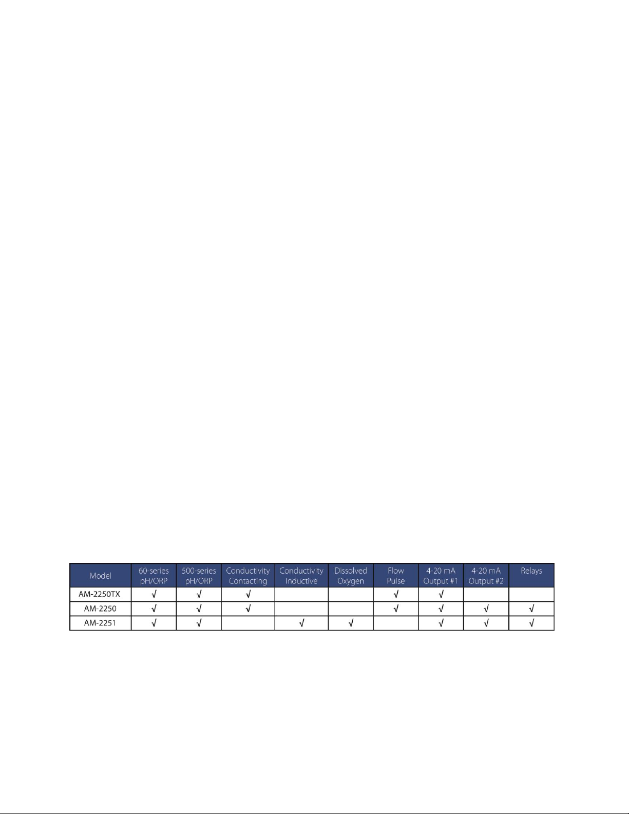
the power-relay circuit board. Because of power constraints the LCD is not backlit. This table summarizes
the parameters the three models measure.
Table 1 - Summary of Analyzers and Associated Probes
Page 6

6
2250-series Operating Manual rev 2.0
2 Specifications
2.1 AM-2250 Technical specs
Probe Parameters
pH
ORP
Conductivity
Flow
Sensor
6-wire differential
or
combination
6-wire differential
or b
combination
2-electrode with
cell constants:
from 0.01 to 100
Pulse output:
Paddle-wheel
Magnetic Flow
Temperature
Elements
Pt100 RTD, Pt1000 RTD, NTC 300Ω, NTC 3000Ω, NTC10k NTC
With Auto Detect Feature
n/a
Sensor Input
-600 to 600 mV
-999 to 999 mV
0 to 9999 Ω
0 to 2000 Hz
Measurement
Range
0 – 14 pH
-20 – 120 0C
-999 to 999 mV
0.055 to 500,000
µS/cm, depending
on cell constant
0 to 9999 in any
available units.
Temperature
Compensation
Automatic, manual
or none
n/a
Automatic, manual
or none
n/a
Calibration Mode
1, 2 or 3 points
Automatic, manual.
Single point.
Manual
Up to 16 points
Wet or dry.
K-factor input
Outputs
Analog
2 x fully scalable and optically isolated 4-20 mA. Max load: 800 Ω
Channel 1: Process with optional PID. Channel 2: Temperature or Process
Relays
3 independent relays:
10A @ 120/240 VAC or 8A @ 30 VDC (Resistive Load)
5A @ 120/240 VAC or 4A @30 VDC (Inductive load)
Relay Modes
Rising/Falling/Range mode, Cycle On/Off, Relay Delay, Overfeed Timer, Override
Ratings
Ingress Protection
NEMA 4X
Electrical
ETL, cETL and CE (pending)
Max. Power Input
0.2 A @ 115 VAC or 15 W
Temperature
-20 to 70 0C
Humidity
0 to 90% Relative Humidity, non-condensing
Physical
Mounting
Wall mount, panel mount with kit provided, pipe mount optional
Dimensions
Front cover: 5.5”x5.5” (14 cm x 14 cm). Depth: 5” (13 cm)
Power
120/240 VAC 60 or 50 Hz
Weight
2 lbs
Page 7

7
2250-series Operating Manual rev 2.0
2.2 AM-2250TX Technical specs
Probe Parameters
pH
ORP
Conductivity
Flow
Sensor
6-wire differential
or
combination
6-wire differential
or b
combination
2-electrode with
cell constants:
from 0.01 to 100
Pulse output:
Paddle-wheel
Magnetic Flow
Temperature
Elements
Pt100 RTD, Pt1000 RTD, NTC 300Ω, NTC 3000Ω, NTC10k NTC
With Auto Detect Feature
n/a
Sensor Input
-600 to 600 mV
-999 to 999 mV
0 to 9999 Ω
0 to 2000 Hz
Measurement
Range
0 – 14 pH
-20 – 120 0C
-999 to 999 mV
0.055 to 500,000
µS/cm, depending
on cell constant
0 to 9999 in any
available units.
Temperature
Compensation
Automatic, manual
or none
n/a
Automatic, manual
or none
n/a
Outputs
Analog
Fully scalable and optically isolated 4-20 mA – Process with optional PID.
Max load: 800 Ω
Relays
None
Ratings
Ingress Protection
NEMA 4X
Electrical
ETL, cETL and CE (pending)
Max. Power Input
20 mA @ 24 VDC
Temperature
-20 to 70 0C
Humidity
0 to 90% Relative Humidity, non-condensing
Physical
Mounting
Wall mount, panel mount with kit provided, pipe mount optional
Dimensions
Front cover: 5.5”x5.5” (14 cm x 14 cm). Depth: 5” (13 cm)
Power
16-32 VDC
Weight
2 lbs
Page 8
8
2250-series Operating Manual rev 2.0
2.3 AM-2251 Technical specs
Probe Parameters
pH
ORP
Conductivity
DO
Sensor
6-wire differential
or combination
6-wire differential
or combination
Inductive
Clark cell
2-electrodes
Temperature
Elements
Pt100 RTD, Pt1000 RTD, NTC 300Ω, NTC 3000Ω, NTC10k NTC
With Auto Detect Feature
Sensor Input
-600 to 600 mV
-999 to 999 mV
Cond: 0 to 9999 Ω
0 to 5000 nA
Measurement
Range
0 – 14 pH
-20 – 120 0C
-999 to 999 mV
0.055 to 500,000
µS/cm, depending
on cell constant
10 ppb to 10 ppm
0 – 110% @ 25°C
Temperature
Compensation
Automatic, manual
or none
n/a
Automatic, manual
or none
Automatic.
salinity, pressure
Calibration Mode
1, 2 or 3 points
Automatic, manual.
Single point.
Manual
Up to 16 points
Wet or dry.
100% and 0% air
Outputs
Analog
2 x fully scalable and optically isolated 4-20 mA. Max load: 800 Ω
Channel 1: Process with optional PID. Channel 2: Temperature or Process
Relays
3 independent relays:
10A @ 120/240 VAC or 8A @ 30 VDC (Resistive Load)
5A @ 120/240 VAC or 4A @30 VDC (Inductive load)
Relay Modes
Rising/Falling/Range mode, Cycle On/Off, Relay Delay, Overfeed Timer, Override
Ratings
Ingress Protection
NEMA 4X
Electrical
ETL, cETL and CE (pending)
Max. Power Input
0.2 A @ 115 VAC or 15 W
Temperature
-20 to 70 0C
Humidity
0 to 90% Relative Humidity, non-condensing
Physical
Mounting
Wall mount, panel mount with kit provided, pipe mount optional
Dimensions
Front cover: 5.5”x5.5” (14 cm x 14 cm). Depth: 5” (13 cm)
Power
120/240 VAC 60 or 50 Hz
Weight
2 lbs
Page 9

9
2250-series Operating Manual rev 2.0
3 Setup
3.1 AC Power Connections (AM-2250 and AM-2251)
Caution: This instrument uses 120 or 240 50/60Hz AC power. Opening the enclosure door exposes you
to potentially hazardous line power voltage which may be present on the power and relay plugs. Always
remove line power before working in this area. If the relay contacts are powered from a separate source
from the line power, be sure to power off before proceeding. The flip-down door contains low voltage
circuitry and is safe to handle. Figure 3-1 shows the controller power board and connectors.
Figure 3-1 Power circuit board showing power and relay connectors. The second 4-20 mA output is also on the board.
To power the controller, remove the 3-pin power terminal block (not shown) and connect the wiring as
printed on the board and shown on Figure 3-2. There are no jumpers or switches to convert the
controller between 120 VAC and 240 VAC; the controller automatically configures for the correct voltage.
Figure 3-2 Power connection for 2250 Controller
Power Connector
4-20 mA Output CH2
Relay Connector
Fuse
Page 10
10
2250-series Operating Manual rev 2.0
3.2 Loop power connection (AM-2250TX)
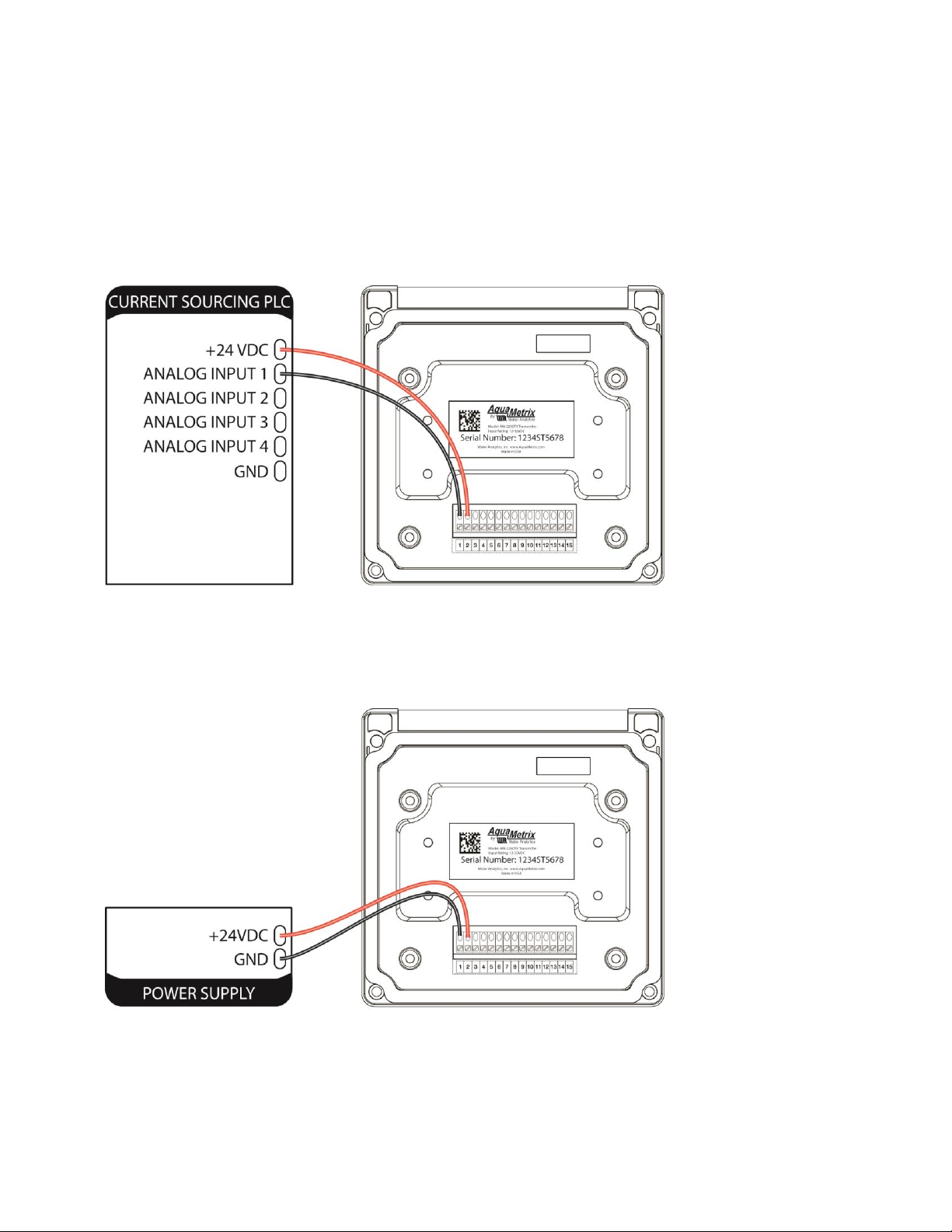
The AM-2250TX is a low-power transmitter that has three options for being powered:
1. Most commonly it is loop powered by a PLC or the AquaMetrix 2300 web-enabled controller. The
AM-2300 Web-enabled controller can power up to four AM-2250TX transmitters using its
internal power supply.
Figure 3-3 Loop powered AM-2250TX from a current sourcing PLC
2. Any current sourcing device supplies between 12 and 32 VDC. In this configuration the 2250TX is
used as a readout device.
Figure 3-4 AM-2250TX wiring with external power supply.
Page 11
11
2250-series Operating Manual rev 2.0
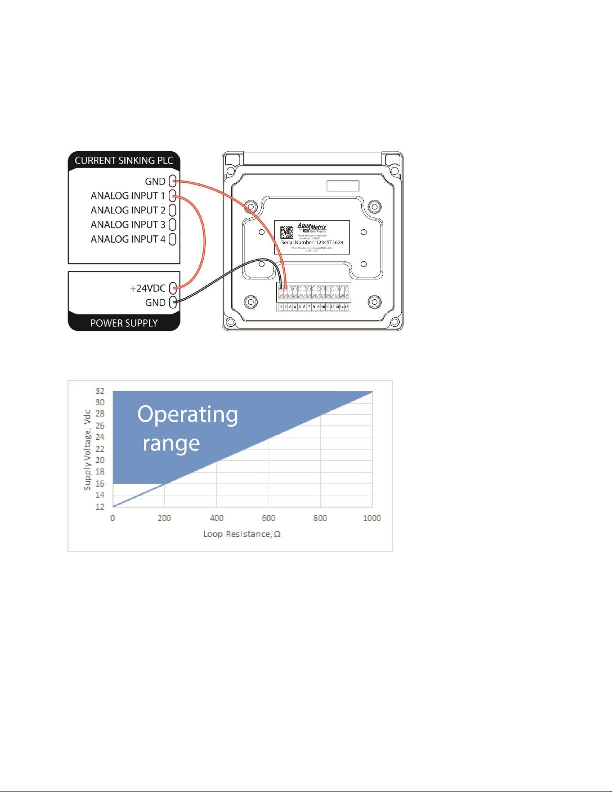
3. The AM-2250TX can be used with a PLC or data logger without internal loop power. Connect the
power supply in series, as shown on the right of Figure 3-5. The required power supply voltage
will vary depending on the resistance in the PLC or recorder. Figure 3-6 shows the power needed
as a function of the PLC loop resistance.
Figure 3-5 AM-2250TX with current sinking PLC
Figure 3-6 Required voltage for power supply for current sinking devices
3.3 Conduit Connection
The 2250 has six ½” (7/8” ID) conduit holes at the bottom of the enclosure. The unit is shipped with three
conduit fitting and three holes plugged with liquid tight conduit seals. These must be left in unused holes
to maintain the NEMA 4X integrity. Use approved conduit glans to ensure ingress protection.
Wire specification: Size and fuse wire according to local electrical code. Maximum current not to exceed
relay specifications when used to power auxiliary devices via internal connections.
Page 12
12
2250-series Operating Manual rev 2.0
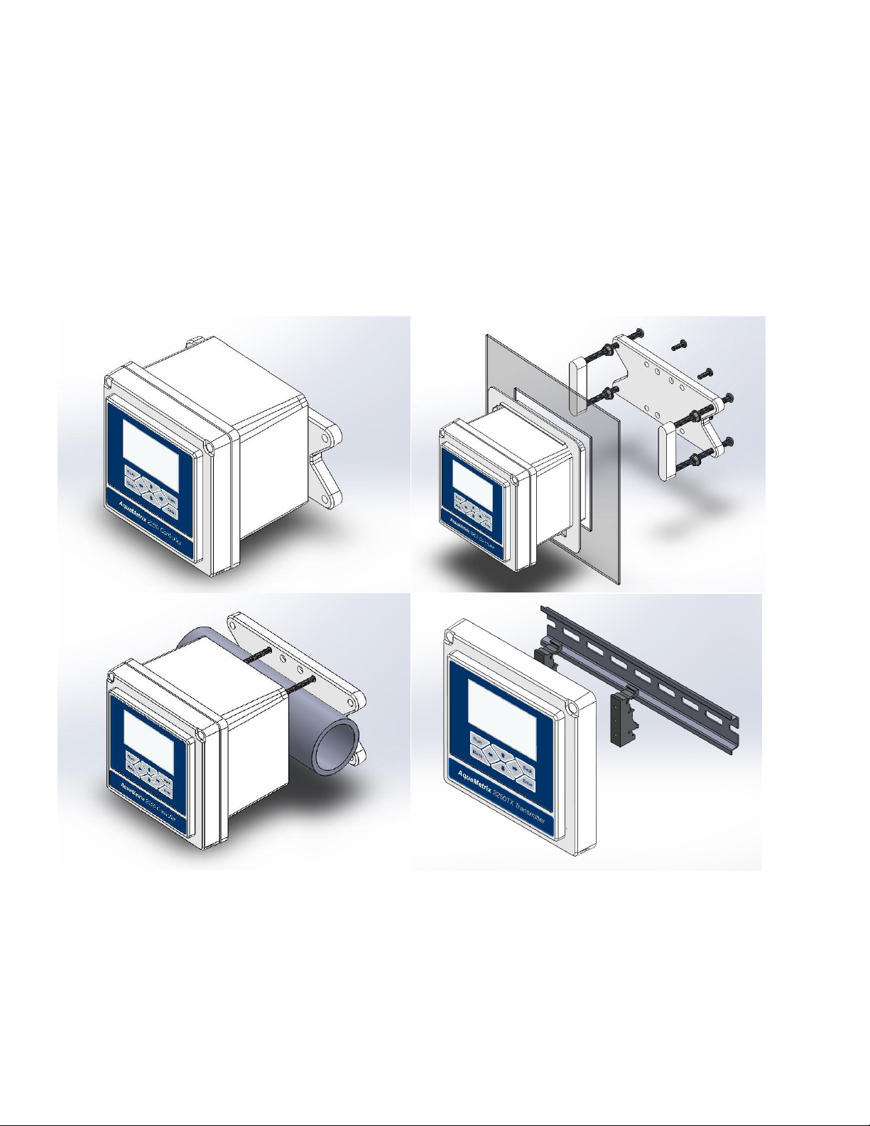
3.4 Mounting
All 2250 series controllers and transmitters can be mounted on a wall, panel or pipe. Figure 3-7 shows
these three options. All hardware for wall and panel mounting is included.
There are two optional kits that are available for sale:
1. 2250-PIPE-MNT is a mounting kit for pipes up to 2”
2. 2250-DIN-MNT is a kit to mount on a DIN rail. Only the 2250TX can be DIN rail mounted. To do so
you replace the back of the transmitter with the mounting brackets.
Figure 3-7 - Four mounting options: wall, panel, pipe and DIN rail (DIN rail option for AM-2250TX only).
Page 13
13
2250-series Operating Manual rev 2.0
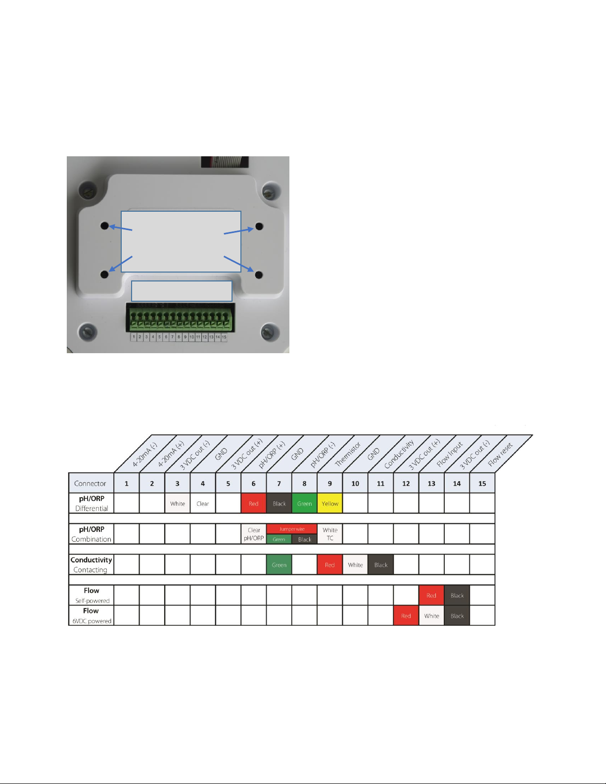
3.5 Connecting Probes
As shown in Figure 3-8, the cover of the cover of the AM-2250 swings open to reveal a connector block
for connecting probes. A label inside the controller identifies the terminals so reference to this manual is
unnecessary. Note than connectors 1 and 2 are used for the 4-20 mA output (CH1) of the AM-2250 and
AM-2251 controllers. The AM-2250TX transmitter also uses them for power input.
Figure 3-8 - This view of the inside of the front cover shows the connector for the probes and mounting holes for DIN rail brackets.
Figure 3-9 and Figure 3-10 shows probe connections to the connector block. The colors of the cells refer
to the colors of the wires of the AquaMetrix probes. Color coding of AquaMetrix differential probes
match that of Hach/GLI analog probes. Other manufacturer probes may use different colors.
Figure 3-9 AM-2250 and AM-2250TX sensor wiring
DIN Rail Bracket
mounting holes
(AM-2250TX only)
Probes Connector
Page 14

14
2250-series Operating Manual rev 2.0
Figure 3-10 AM-2251 sensor wiring
All AquaMetrix pH and ORP sensors can be connected to any 2250-series analyzer. Table 1 lists the set of
probes that connect to all three analyzers.
Figure 3-11 Sensor compatibility chart
3.6 Analog (4-20 mA) Outputs
The AM-2250TX contains one 4-20 mA output that is isolated from sensor input. It is the two terminals 1
and 2 on the probe connector as mentioned in the last section. The output can be configured for process
value; it is reversible and scalable. It can also be configured for PID control. The output is labeled as “4-20
channel 1” or “CH1” in menu.
The AM-2250 and AM-2251 additionally have a second isolated, reversible and scalable 4-20 mA output
that can be configured for either the process value or temperature. It is located on the power supply
board, which is shown in Figure 3-1. The 2 push-pin connector is on the lower right of the board, next to
relay connector.
Page 15
15
2250-series Operating Manual rev 2.0
3.7 Relays (AM-2250 and AM-2251)
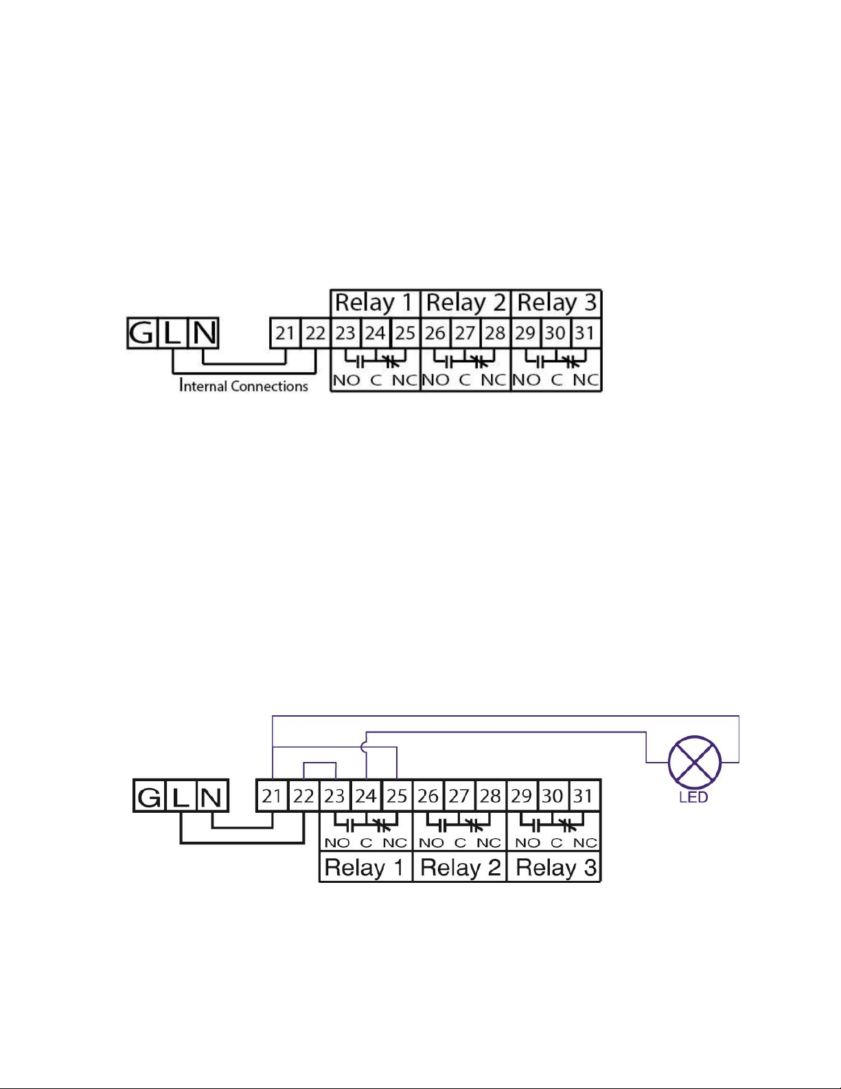
3.7.1 Wiring relays
The AM-2250 and AM-2251 contains three dry contact relays. For a resistive load they are rated 10A @
120/240 VAC or 8A @ 30 VDC. For an inductive load they are rated 5A @ 120/240 VAC or 4A @30 VDC.
Though these relays will work in most process control applications, we advise, for safety reasons, to use
them as switches, i.e. low power DC relays that activate a second set of AC-powered relays separate from
the controller.
Figure 3-12 Wiring connections to the three relays. All relays are powered by internal jumpers between the ac power and
terminals 21 and 22.
3.7.2 Snubber
When a relay is used to control an inductive device (relay coil, solenoid, transformer, small motor, etc.),
the energy stored in the device will subject the relay contacts to a high voltage when the relay opens.
When the switch contacts open, the contact gap is initially small. Arcing across this contact gap can occur
immediately after the switch opens. This can happen in resistive as well as inductive loads, but inductive
loads generate a higher voltage and causes increased arcing. Increased arcing decreases relay life. Arc
suppression requires the use of an RC suppression network, called a snubber.
Each relay of AM-2250 and AM-2251 is connected to a snubber. Despite the fact that snubber prolongs
relay life they have one disadvantage – they leak a small amount of AC current. If there is a low power
LED or voltage meter connected between the COM and NO (or NC) terminals there will always be some
AC voltage across them. If your application requires having only an LED use the alternative wiring shown
in Figure 3-13 below.
Figure 3-13 Alternative wiring for low power equipment (LED) only
Page 16

16
2250-series Operating Manual rev 2.0
4 Probe Setup
When powering up the 2250 the first screen presents options for configuring sensors.
Figure 4-1 Initial start-up screen
1. Use the ↑ and ↓ buttons to scroll through the menu.
2. Use the and → buttons to move the cursor left or right.
3. Press Enter to select or confirm a selection.
4. Press Back to return to the previous screen or cancel your choice.
5. Press Menu to return to the main menu.
6. Press Run to exit from any menu and display the run display.
The top-level menu allows the user to configure the 2250 for a pH, ORP, conductivity, DO or flow sensor.
The Setup option in the top-level menu allows you to completely configure a new probe or change an
existing one.
4.1 pH
1. Scroll down the top-level menu to select Setup and press the Enter key.
2. Press Probe Selection.
3. Select pH and Press Enter. (As the first item in the list it is the default choice.)
4. The next menu lists the configuration options for the pH probe.
Page 17

17
2250-series Operating Manual rev 2.0
5. Type is either Combination or Differential.
The 2250 will accept virtually any combination or differential sensor. Entering a probe as the wrong
type will simply result in an artificial offset and may not cause any noticeable reading or error.
Combination probes may consist of only two wires for the process and reference or four wires, which
includes two leads for the temperature element. Differential probes always have five or six (Including
the shield) wires.
6. All differential probes and four-wire combination probes have a temperature element that must be
selected. There are two types of temperature elements: RTD’s (Resistive Temperature Device) and
NTC’s (Negative Temperature Coefficient). As the name implies, am NTIC displays a negative
temperature correlation while a an RTD shows a positive one.
Select Temp Element to bring up the choices of temperature element:
AUTO DETECT recognizes most temperature devices. If it fails to properly configure the temperature
device, check the temperature element wiring.
7. Select the preferred units of temperature (Temp Unit):
8. Choose whether you want to keep temperature compensation.
The default selection is On. as most application requires pH slope to be corrected for temperature.
9. Press Run to confirm that controller displays pH units and reasonable temperature values.
Page 18

18
2250-series Operating Manual rev 2.0
4.2 ORP
As with pH probes all differential ORP probes and four-wire combination probes contain temperature
elements. However, ORP values are NOT temperature compensated. The temperature value is only for
informational purposes.
1. From the top-level menu select Setup and press the Enter key.
2. Press Probe Selection to choose the probe type, ORP.
3. This selection automatically brings up the next menu for defining the configuration of the ORP probe.
4. Type sets the probe as a Combination or Differential probe.
As with pH probes, the 2250 will accept just about any type of combination or differential ORP probe.
Entering the wrong type will simply result in an artificial offset and should not cause any noticeable
reading or error. Combination probes may consist of only two wires for the process and reference or
four wires, which includes two leads for the temperature element. Differential probes always have
five or six (with the shield) wires.
5. With the exception of the two-wire combination probe, the type of temperature element must be
selected. There are two types of temperature elements: RTD’s (Resistive Temperature Device) and
NTC’s (Negative Temperature Coefficient). As the name implies, an NTIC thermistor displays a
negative temperature correlation while a an RTD shows a positive one.
Select Temp Element to bring up the choices of temperature elements:
AUTO DETECT recognizes most temperature devices. If it fails to properly configure the temperature
device, check the temperature element wiring.
Page 19

19
2250-series Operating Manual rev 2.0
6. Select the preferred units of temperature (Temp Unit):
7. Press Run to confirm that controller displays mV units and reasonable temperature values.
4.3 Conductivity
1. From the top-level menu select Setup and press the Enter key.
2. Press Probe Selection to choose the probe type, Conductivity, and press the Enter key.
The AM-2250 and AM-2250TX work only with contacting conductivity sensors. The AM-2251 works
only with toroidal (also called non-contacting, inductive or electrodeless) sensors. The screen in the
left shows the setup screen for a contacting conductivity sensor for the AM-2250 or AM-2250TX. The
screen on the right shows the setup screen for a toroidal sensor.
3. This next menu defines the configuration of the conductivity sensor.
4. Cell constant selection.
AM-2250 & AM-2250TX: To enable the user to confirm that the cell constant is appropriate for his
application, the 2250 menu for cell constants lists the approximate conductivity range for each cell
constant It’s important to understand that, although you are free to choose any cell constant, you
will get inaccurate readings unless you choose the correct one. For instance, if your probe has a cell
constant of 1 and you choose 0.1 (perhaps in an effort to measure lower conductivity levels) your
readings will be high by a factor of 10. The cell constant is typically written on a label attached to the
cable.
Note that the AM-2251 does not have a menu for the Cell Constant. The cell constant was originally
defined as a geometric factor between electrodes (distance between electrodes/area). A cell
constant can be viewed simply as a proportionality constant between conductance (e.g. µS) and
conductivity (µS/cm) and thus a cell constant can be linked to a toroidal probe, the 2251 uses an
analogous factor, called the transfer function.
AM-2251: The menu for the 2251 conductivity probe configuration therefore does not contain the
cell constant.
Page 20

20
2250-series Operating Manual rev 2.0
All conductivity sensors can measure conductivity values outside their ideal measurement range but
the accuracy of the readings will suffer due mainly to the non-linear relationship between the reading
and the conductivity value.
5. Choose Temperature Element.
Conductivity readings are strongly influenced by temperature so nearly all conductivity probes have
temperature elements. The same choices for temperature element for pH and ORP are present for
conductivity. The default element for AquaMetrix AM series probes is the 1000 Ω RTD so that option
is the default value.
6. Select Temperature Unit. Choices are Fahrenheit (°F) Celsius (°C) or Kelvin (K).
7. Conductivity values span a range of a million to one so one unit for representing all possible
values is impractical. The metric (MKS) unit is Siemens/m. However, 1 S/m represents a level of
conductivity higher than any water sample normally measured. Therefore, units of one
thousandth of a Siemen per centimeter, mS/cm, or one millionth of a Siemen per centimeter,
µS/cm.
The choices for Conductivity Unit are listed as:
µS/cm. For clean, tap, surface or ground water this unit is the most common. RODI water
typically has conductivity of 1 µS/cm or less. Tap water is around 300 µS/cm.
mS/cm. Salt solutions, acid and bases use the higher range. 1 mS/cm = 1000 µS/cm. Confusion
between the two is responsible for nearly all problems selecting conductivity sensors and setting
up the correct range.
Page 21

21
2250-series Operating Manual rev 2.0
MΩ-cm. For very pure water many workers prefer to report resistivity units in place of
conductivity units. One is the inverse of the other. Ultrapure water has a resistivity of 18.8 MΩ-
cm (0.055 µS/cm). (Its finite resistance is the result of H+ and OH- ions.)
TDS (mg/l). The correlation between total dissolved solids (TDS) and conductivity varies with
every sample of water. In order to display conductivity in terms of TDS units one must choose a
conversion factor. The default value is 0.65 mg/l = 1 µS/cm. This menu selection allows you to
select the conversion factor of TDS units to µS/cm units.
The only way to get an accurate conversion factor is to measure the TDS value by evaporating the
water from a sample and weighing the leftover solids.
Concentration (%). This unit, in terms of weight per volume, is a TDS unit express as g/l. It is used
for very high concentrations. It is typically used to characterize acids and bases. In order to
display conductivity in terms of concentration units one must choose a conversion factor that
converts mS/cm to %. The default value is 1 mS/cm = 0.5000 %.
8. Temperature Compensation. Over a limited temperature range the variation of conductivity with
temperature is linear. Conductivity values are typically reported in the literature at 25 0C.
The default value for α is 2.00 per degree C or 1.10 per degree F.
9. Temperature compensation for most applications should always be On.
However, for diagnostic purposes and some isolated cases where you need to know the actual
conductivity (and not the value at 250C) turn compensation Off.
10. Press Run to confirm that selected conductivity and temperature units are displayed correctly.
Temperature may not be very accurate without calibration but should be close to expected value.
Page 22

22
2250-series Operating Manual rev 2.0
4.4 Dissolved Oxygen (AM-2251)
1. Scroll down the top-level menu to select Setup and press the Enter key.
2. Press Probe Selection and choose the probe type, DO.
3. This selection automatically brings up the next menu that defines the configuration of the DO
sensor.
4. Choose the appropriate Temperature Element
DO sensors are typically equipped with one or two temperature elements. In older D.O. probes (like the
AquaMetrix P91) a second temperature element is used as an analog approximation to the change in
membrane permeability with temperature. In newer probes, like the AM-CDO one temperature element
is used to calculate both the membrane permeability factor as well as the conversion from % saturation
to concentration (ppm or ppb) units.
5. Select Temperature Unit
6. The choices for DO units are %sat (saturation) or ppm/ppb (concentration). PPB units are used in
applications where oxygen concentration values are extremely low, e.g. in boilers.
7. DO value depends on the ambient (i.e. atmospheric) pressure therefore Pressure Compensation
should be On..
Page 23

23
2250-series Operating Manual rev 2.0
The AM-2251 controller contains a pressure sensor that measure atmospheric pressure so
manual entry is not required.
8. Salinity also affect the concentrations of oxygen in water. The amount of oxygen that can dissolve
in water decreases as salinity increase. Seawater solubility is about 20% less compared to fresh
water. Salinity is usually expressed in ppt (g/l) units. In most applications the salinity value should
be between zero (fresh water) and 40 ppt.
9. Press Run to confirm that selected DO and temperature units are displaying correctly. Even
without temperature calibration the temperature reading should be within 1 °C of the correct
value.
4.5 Flow (AM-2250 and AM-2250TX)
Any flow sensor that outputs a pulse will work with the AM-2250 and AM-2250TX. This includes paddle
wheel meters and magnetic flow meters (aka “magmeters”). The 2250 measures both instantaneous flow
and totalized flow. The latter is a running total of the volume and is equal to the flow integrated over
time.
1. Scroll down the top-level menu to select Setup and press the Enter key.
2. Press Probe Selection to choose the probe type, Flow.
3. The following screen should appear
4. Set Volume Units. Choices are gallons, ft3, cm3 and liters.
5. Set Time units.
Page 24

24
2250-series Operating Manual rev 2.0
6. Press Run to confirm that the selected flow unit displays correctly. Most flow sensors don’t have
a temperature device, so the total flow value replaces the usual temperature value.
4.5.1 Totalizer Reset.
There are two ways to reset the totalizer.
1. The first option is via software: Navigate to Menu > Setup > Probe Config >Totalizer reset. After
confirming that you really do want to reset the totalizer it will start again at 0.
2. There is also an option to reset the flow totalizer using hardware: Short pins 14 and 15 of the
probe connector.
Figure 4-2 Flow Totalizer Reset using probe connector
This hardware reset can be done via an external button or switch. For automating daily totals a
mechanical or electrical timer can be used to short pins 14 and 15 at the start of each day.
5 Calibration
The Calibration menu automatically presents choices appropriate for the probe chosen. If the menu
choices for calibration appears wrong, you probably chose the wrong probe.
Note: If you select the probe type and wish to immediately calibrate you must put the controller in Run
mode first. You can press the Run button while in any menu.
Page 25

25
2250-series Operating Manual rev 2.0
5.1 pH
5.1.1 About pH Calibration
Most pH analyzers allow the user to calibrate a probe with only two points, using two of three standard
calibration solutions: pH 4, 7 and 10. For two-point calibration use the two standards that are closest to
your expected process values. For example, if your process is mostly acidic (< pH 7) then calibrate using
standards pH 4 and pH 7.
For the highest accuracy of pH readings that span a wide range encompassing neutral (7) the 2250 offers
the option of three-point calibration. An algorithm uses linear least squares to calculate the slope. It is to
algorithms that just interpolate between the two pairs of neighboring points.
A pH probe that operates according to theory outputs 59.16 mV at 250C for every unit change in pH. The
actual change in output for a real probe is likely to be different and is the slope for that probe. An ideal
probe in pH 7 solution (at 250C) outputs 0 volts. The actual output is likely to be different and is the
offset. The slope yields the efficiency of the probe. A probe that outputs 59.16 mV at 250C is 100%
efficient. If the probe outputs, say, 57.34 mV then the efficiency is 96.9% efficient.
When a probe leaves the AquaMetrix factory it is tested three times to ensure that its offset and
efficiency are within an acceptable tolerance (±50 mV and >90% slope, respectively). As probes age their
efficiency decreases. Note that a probe with low efficiency will still be accurate but it will not be precise,
i.e. its reading will have a large uncertainty. We recommend cleaning or replacing a sensor when its
efficiency drops below 80%. Before discarding a probe showing low efficiency make clean it according the
probe manual’s instruction or the AquaMetrix video
https://www.wateranalytics.net/home/support/training-videos/. A large offset usually indicates that the
reference solution is contaminated and should be replaced.
5.1.2 Two-Point Calibration
As stated above, use the two calibration standards that encompass the pH range of your process.
There is a choice between auto and manual calibration.
5.1.2.1 Auto Calibration
In auto calibration the 2250 reads the probe output when it is in a buffer and decides whether the buffer
is pH 4, 7 or 10. Ideal voltages for these buffers are 177, 0 and -177 mV. If the output of the probe is
within 59.16 mV (1 pH unit) from any of these values auto calibration assumes it “knows” the calibration
standard in which the probe is immersed. If the output is greater than 59.16 mV auto calibration will fail.
Page 26

26
2250-series Operating Manual rev 2.0
There are several reasons why this can happen:
1. The offset of the probe is greater than 59 mV.
2. The buffer is non-standard (i.e. neither 4, 7 or 10).
3. The buffer has aged and is no longer at its nominal pH value.
To initiate auto calibration:
1. Select Auto Calibration
2. Follow the directions on the next screen and immerse the probe in the first calibration standard.
Allow at least one minute for the probe reading to settle down. It helps to swirl the probe
around in the solution. After a minute or longer press the Enter key as instructed. (If you press
the Enter key too soon the analyzer will accept an inaccurate probe reading and the efficiency is
likely to be lower that it should.)
3. The screen will display Calibrating for a few seconds as it reads the probe output and stores the
probe output value. The next screen will appear and will direct you to immerse the probe in the
second calibration standard. (Always rinse the probe in clean tap water before immersing it in a
new buffer.) As before, wait at least one minute before pressing Enter to record the probe output
value of the second calibration solution.
4. The screen will again display Calibrating for a few seconds and will display the results of the
calibration—the efficiency and offset. An example is:
If you are satisfied with the measured efficiency and offset, press Enter to accept the calibration.
If not press Back to repeat calibration. Pressing Menu brings you back to the top menu.
Page 27

27
2250-series Operating Manual rev 2.0
5.1.2.2 Manual Calibration
As explained above manual calibration can be used if the probe has a very large offset, has low efficiency
or is being calibrated with non-standard buffer solutions.
1. Select Manual Calibration
2. Place the probe in the first buffer. As opposed to auto calibration, it is okay to press Enter
without waiting for the probe output to settle down. The next screen will display the current
output reading of the probe.
3. When the reading settles down press Enter. The next screen allows you to change the value of
the displayed pH value to correspond to the actual pH of the calibration solution. Use the ↑ and
↓ arrow buttons to change the value and the or → button to change the cursor position.
Press the Enter key to lock in the correct value.
4. The results of the calibration (identical to the one shown for auto calibration) will display.
5. Place the probe in the second buffer. Again, there is no need to wait for the probe reading to
settle down prior to pressing Enter.
6. When the reading settles down press Enter. Change the pH value display to equal the pH of the
calibration standard.
5.1.3 3-Point Calibration
The instructions for 3-point calibration are the same as for 2-point calibration with the obvious exception
that three standards are used instead of two.
5.1.4 Temperature Calibration
Since all pH readings are temperature compensated, an accurate pH readings depend on an accurate
temperature.
1. Select Temperature.
2. The screen displays the current temperature reading. Make sure the temperature reading has
settled down. Keep in mind that most temperature elements in pH probes are encapsulated
inside the probe, which results in a temperature lag of several minutes for the element to
equilibrate with the temperature of the solution.
3. The temperature calibration procedure is analogous that for manual pH calibration. It’s not
necessary to immerse the probe in solution. Knowing room temperature enables you to calibrate
the probe in air. As with manual pH calibration, ensure that the temperature reading settles
Page 28

28
2250-series Operating Manual rev 2.0
down prior to pressing Enter. The next screen allows you to change the temperature reading to
match the actual temperature. Press Enter when done or Menu to go back to the top menu.
5.2 ORP Calibration
5.2.1 About ORP Calibration
ORP is a unique water quality parameter. For all other parameters a voltage, current or other electrical
change corresponds to a value of the parameter and calibration determine that relationship. For
instance, a pH probe generates a voltage that maps to a pH value. The ORP unit of measurement is
different. It IS the actual output voltage of the probe. No translation to a dependent parameter takes
place. An ORP analyzer is just a voltmeter. Therefore, no calibration is needed.
However, all voltmeters need to be calibrated. The only practical way of doing so for an ORP analyzer is
to measure the offset of the voltmeter. This is called a standardization. This requires only one
measurement. Though ORP calibration is strictly not a calibration we often refer to the standardization as
a calibration. This manual follows this practice.
To “calibrate” an ORP probe simply immerse it in a calibration standard that produces a known voltage
and adjust the reading of the analyzer until it matches the actual value of the solution.
There are no standard calibration solutions for ORP although Zobell’s (228mV @25°C) and Light’s (476mV
@25°C) solutions are the most commonly used. AquaMetrix makes its own versions of these two
solutions that are nominally 200 and 600 mV. ORP solutions are not buffered which means that their ORP
values are not as stable as pH buffered standards are. Each calibration solution AquaMetrix is
characterized by an ORP value that may vary within 20 mV of the nominal 200 or 600 mV value. The
solution bottle will list the actual mV value. This value will change as chemicals in the solutions slowly
oxidize, so ORP calibration solutions should be replaced at least every 6 months.
5.2.2 ORP Calibration
For reasons just stated, ORP calibration is a manual, one-point procedure.
1. Select ORP Calibration.
2. Place the probe in the calibration standard and press Enter. As in all manual calibrations there is
no need to wait prior to pressing Enter.
Page 29

29
2250-series Operating Manual rev 2.0
3. Observe the probe output reading and, when it has settled down, press Enter.
4. Adjust the value displayed in the next screen until it matches that of the calibration standard.
Note that ORP standards can be negative so be careful to select the correct + or - sign.
5. As the screen instructions state, press Enter to accept the calibration or Back to repeat it.
Pressing Menu brings you back to the top menu.
5.2.3 Temperature
1. Select Temperature.
2. The screen displays the current temperature reading. Make sure the temperature reading has
settled down. Keep in mind that most temperature elements in pH probes are encapsulated
inside the probe, which results in a temperature lag of several minutes for the element to
equilibrate with the temperature of the solution. As mentioned for pH probes, you can calibrate
temperature in air—as long as you know room temperature.
3. Temperature calibration is similar to manual pH calibration. When the temperature reading
settles down press Enter. The next screen allows you to change the temperature reading to the
actual temperature. Press Enter when done or Menu to go back to the top menu.
5.3 Conductivity
The AM-2250 and AM-2250TX can work with contacting conductivity sensors (AS- and AM-series), while
the AM-2251 can only work with toroidal (aka inductive or non-contacting) sensors. The calibration menu
for the AM-2250 or AM-2250 TX is show on the left. The menu for the AM-2251 is shown on the right. It
has a few more options.
Page 30

30
2250-series Operating Manual rev 2.0
5.3.1 About Conductivity Calibration
As with ORP calibration there are no recognized standard calibration standards so there is no auto
calibration option. Also, as with ORP, conductivity calibration standards are not buffered and can change.
Stability of the conductivity standard is only a problem for standards of very low conductivity, where
introduction of impurities in the solution can induce large changes in conductivity. At conductivity
standards below 5 µS/cm just carbon dioxide in the air can increase the actual conductivity.
In those cases where a conductivity standard is not available one may enter the cell constant of the probe
as an approximate surrogate to calibration. Obviously, the calibration using the known cell constant is
only as good as the cell constant is known. Usage of the probe will cause some scaling or fouling of the
electrodes, which will result in an increased nominal cell constant. Therefore, calibration using real a real
conductivity standard is always preferred.
Most conductivity analyzers employ a calibration routine that uses only one calibration standard. This is
actually a two-point calibration routine inasmuch as the other point is assumed to be zero, i.e. that the
conductivity for a zero-conductivity sample is zero. The AM-2250 allows as many as 16 points. Though
one point is sufficient for most applications the ability to calibrate over several points allows one to use
conductivity measurements to determine acid and base concentrations. As the figure below shows
conductivity as a function of acid/base concentration is very non-linear and, therefore, several points are
needed to construct the curved relationship. Therefore, multi-point calibration also enables greater
accuracy over a wider range of conductivities.
Figure 5-1 Relationship between Concentration of solution and conductivity (at 25° C)
5.3.2 Manual Conductivity Calibration or Wet Calibration
The procedure for manual conductivity calibration is similar to that for manual pH and ORP calibration.
The only exception is that user can calibrate using as many as 16 points.
1. Select Manual Calibration.
2. Select the number of calibration standards to be used. In most cases choose 1. For greater
accuracy choose 2 or 3. Only for measuring acid and base concentrations or conductivities over a
wide range are more points needed. Press Enter to accept the number of points.
0
100,000
200,000
300,000
400,000
500,000
600,000
700,000
800,000
900,000
1,000,000
0 10 20 30 40 50 60 70 80 90 100
Conductivity, µS/cm
Concentration, %
NaCI
NaOH
HCI
H2SO4
HNO3
HF
Page 31

31
2250-series Operating Manual rev 2.0
3. Immerse the probe in the first (or only) calibration standard. Press Enter.
4. The display will show the current conductivity reading. Adjust the conductivity reading to match
the actual conductivity value of the standard.
5. Repeat for additional standards if there are any.
6. Press Enter to accept the calibration or Back to discard it.
5.3.3 Cell Constant
As explained above this procedure substitutes actual calibration with the input of the known cell
constant. One might assume that this is the same cell constant value input during the Setup procedure.
However, the actual cell constant of the probe is likely to be different from the nominal cell constant. For
instance, the cell constant for a probe with nominal cell constant 1.0 cm-1 may actually be 1.05 cm-1. If the
actual cell constant is known, then this calibration option allows one to input it.
1. Select Cell Constant.
2. In the next screen enter the cell constant. Possible values are 0.01 to 999 cm-1.
3. Press Enter when done.
4. Press Enter to accept or Back to cancel.
5.3.4 Temperature
The temperature dependence of conductivity is more pronounced than it is with pH or ORP. Temperature
calibration is therefore critical.
1. Select Temperature.
2. The screen displays the current temperature reading. Make sure the temperature reading has
settled down. Keep in mind that most temperature elements in pH probes are encapsulated
inside the probe, which results in a temperature lag of several minutes for the element to
equilibrate with the temperature of the solution. As previously stated temperature calibration
can be done in air.
3. Temperature calibration is similar to manual pH calibration. When the temperature reading
settles down press Enter. Adjust the temperature reading to match the actual temperature. Press
Enter when done or Menu to go back to the top menu.
Page 32

32
2250-series Operating Manual rev 2.0
5.3.5 Dry Conductivity Calibration (AM-2251)
In a case of toroidal (inductive) conductivity sensor there is a coefficient that characterizes the
relationship between the voltage of the drive coil and the voltage of the receive coil—the transfer ratio.
The transfer ratio typically varies from one sensor to another even for the same model.
Some probes arrive with a transfer ratio already measured at the factory. If not, it can be precisely
measured with just a resistor. Figure 5-1 shows how:
1. Splice a wire to a through-hole resistor. For best results use a resistor whose value is between
100 Ω and 1000 Ω (1% accuracy or greater).
2. Insert the wire-resistor combination through the toroidal probe and splice the loose end of the
wire to the loose end of the resistor, thus creating a loop. The length of the wire is not important
as long as it does not add resistance. You can use alligator clips to splice the wire and resistor.
Figure 5-1 Dry calibration setup using resistor attached to a wire
1. Select Dry Calibration.
2. Press Enter.
3. The display will show the current resistor reading. Press Enter when reading settles adjust the
resistor reading to match the actual value.
4. Press Enter to accept the calibration or Back to discard it.
Page 33

33
2250-series Operating Manual rev 2.0
5.3.6 Zero Offset Calibration (AM-2251)
Zero offset calibration is only necessary for conductivity values less than 50 µS/cm. The zero offset should
remain stable over time, so its calibration needs to be done only once if no changes are made to the
sensor, controller or installation environment.
1. Select Zero Offset Cal.
2. Ensure that the sensor (dry) is far from possible sources of electromagnetic emission (VSD,
transformers etc). Press Enter.
3. The display will show the current reading in air. Press Enter when stable. If the values fluctuates
there is ambient EM noise. Move the sensor around until the reading becomes more stable.
4. Press Enter to accept the calibration or Back to discard it.
5.3.7 Transfer Ratio (AM-2251)
If the transfer ratio is already known (either supplied by the manufacturer or previously measured) then
a dry calibration is not necessary.
1. Select Transfer Ratio.
2. Using the keypad to enter the known transfer ratio value. Press Enter.
5.4 Dissolved Oxygen (AM-2251)
It is important to know that any amperometric sensor (like Clark cell) requires polarization, i.e. sensor has
to be connected to the power/controller for up to 12 hours until readings are stable. Make sure that
sensor was fully polarized before start calibration.
Also, due to pressure and temperature dependency calibration must be performed on installation site.
Page 34

34
2250-series Operating Manual rev 2.0
5.4.1 About DO calibration
For most applications single point DO calibration is sufficient. As with conductivity calibration a second
point assumes zero signal at zero DO. DO sensors respond neither to concentration nor %-saturation.
They respond to oxygen gas partial pressure (the 21% of the atmosphere comprised of oxygen) and,
though it may seem counterintuitive, the gas pressure in ambient air is the same as that in fully saturated
water. The analyzer algorithms uses the partial oxygen pressure to convert the probe reading to %saturation and it uses the temperature and salinity to convert the partial pressure to concentration.
There are no calibration standards available. Because the %-saturation reading is the same in the air as it
is in fully saturated water one can calibrate a DO sensor simply by holding it in the air. For greatest
accuracy the air should be fully saturated with water vapor. Holding sensor directly above water surface
or enclosing the probe in a sealed, moist container will guarantee an accurate calibration. Alternatively,
you can calibrate the probe by immersing it in a sample of water containing an air-stone Keep in mind
that there must be flow across the surface of an electrochemical D.O. probe to achieve an accurate
reading.
For applications containing very low DO concentrations (e.g. boilers and de-aerators) it is important to
measure the zero point rather than assume that the signal is zero. To do so requires adding a reducing
chemical to remove all dissolved oxygen.
Over time both the slope and offset will change. Refilling the electrolyte, polishing the cathode and
periodically replacing the membrane will minimize this change.
5.4.2 DO Calibration
Accurate DO measurement requires a fully-polarized sensor, stable temperature and constant pressure.
1. Select DO Calibration.
2. Hold sensor above water or enclose the probe in the water saturated bag (or cap). Press Enter.
3. The display will show the current reading in µA. The value is unique for each sensor. For a fully
polarized AM-CDO it should be around 4uA. Press Enter when reading settles.
Page 35

35
2250-series Operating Manual rev 2.0
4. Press Enter to accept the calibration or Back to discard it.
5.4.3 Zero Offset Calibration
The factory default value for zero D.O. is 0 nA offset. In order to calibrate the actual offset, a fresh 0%-sat
solution must be prepared. Do not stir it as this may force oxygen absorption.
1. Select Zero Offset Cal.
2. Submerse sensor in 0%-sat water. Press Enter.
3. The display will show the current reading in nA. It may take several minutes to reach absolute
minimum (ideally 0 nA). Press Enter when the reading settles.
4. Press Enter to accept the calibration or Back to discard it.
5.4.4 Temperature Calibration
As stated above a dissolved oxygen sensor uses temperature to calculate D.O. concentration. It also uses
the temperature reading to estimate the membrane permeability, which affects the D.O. reading.
1. Select Temperature.
Page 36

36
2250-series Operating Manual rev 2.0
2. The screen displays the current temperature reading. Make sure the temperature reading has
settled down. Keep in mind that most temperature elements in pH probes are encapsulated
inside the probe, which results in a temperature lag of several minutes for the element to
equilibrate with the temperature of the solution.
3. Temperature calibration is similar to manual pH calibration. When the temperature reading
settles down press Enter. The next screen allows you to change the temperature reading to the
actual temperature. Press Enter when done or Menu to go back to the top menu.
5.5 Flow (AM-2250 and AM-2250TX)
5.5.1 About Flow Calibration
There is no actual calibration procedure for a flow meter. The K-factor supplied by the manufacturer sets
the conversion between the meter’s pulse frequency and velocity of water flowing past the probe. The
latter is proportional to the flow rate, with the proportionality constant dependent on the cross-sectional
area of the pipe. The inner diameter of the pipe therefore allows the flow sensor manufacturer to
convert the fluid velocity (e.g. cm/sec) into a flow rate (e.g. cm3/sec).
For most applications the K-factor supplied by the manufacturer and is sufficient to yield accuracy of
better than 5%. For greater accuracy one can determine the actual K-factor by measuring the time it
takes to fill a container with a known volume of water.
5.5.2 Flow Calibration
To input the K-factor:
1. Select Manual. (It’s currently the only choice but future firmware versions may allow the
experimental determination of the K-factor though the exercise of filling a container with water.)
2. Enter the K-factor. It’s important that the flow units of the K-factor are the same as the units
selected during setup. If they are different then go back to Setup and change the units.
Alternatively, one can perform unit conversion arithmetic to ensure that the K-factor entered
has the units selected during setup.
3. Press Enter.
4. Press Enter again to accept the K-factor or Back to cancel.
Page 37

37
2250-series Operating Manual rev 2.0
6 Output
The AM-2250TX transmitter has one 4-20mA output with optional PID.
The AM-2250 and AM-2251 has two output modes:
1. Three dry contact relays
2. Two isolated 4-20 mA current outputs (Channel 1 with optional PID)
When the 2250 is used for process control then one to three of the relays are configured. When the 2250
is used in conjunction with PLC’s or SCADA systems then the 4-20 mA outputs are configured. PID control
is used for fine control of a process using the 4-20 mA output on the main board.
6.1 Relays (AM-2250 and AM-2251)
The AM-2250 and AM-2251 is equipped with three relays. Three relays give users the capability of
controlling a falling process, rising process and a physical alarm.
Note: All instructions assume a relay is wired as normally open (NO). If a relay is wired normally closed
(NC) then activate or open should be reversed, i.e. deactivate or close.
Relay 1 Relay 2 Relay 3
Relay 3 has additional option that allows activate relay based on temperature value. Other selections are
identical for all three relays.
6.1.1 Relay mode
There are three relay mode available: rising, falling and range alarm:
1. A rising process is one that triggers a relay when the process value rises above the set-point.
2. A falling process triggers a relay when the process value drops below the set-point.
3. A range alarm is triggered when the process value is (a) either above the high set-point or below
the low set-point or (b) inside the two set-points. In most applications it is an out-of-range alarm.
Page 38

38
2250-series Operating Manual rev 2.0
For rising and falling setpoint there is a second setpoint at which the relay deactivates. The gap between
the set-point and the deactivation point is the dead-band. For instance, if you may be controlling a
process whose pH naturally rises. If you want to lower the pH when it reaches pH 9 then set the relay
set-point to 9. Presumably, at pH 9, a relay closes and starts a pump, which dispenses acid to bring the pH
back down below 9. The pH value at which the relay opens again must be less than 9. If it is too close to
9.0, e.g. 8.9, the chemical pump will cycle on and off too frequently. Even more problematic is the relay
activating before the pH has a chance to equilibrate. The result is that the process is never stabilizes. For
these reasons the relay deactivation must be sufficiently below the activation, e.g. pH 8.0 in this menu
figure below.
For obvious safety reasons, the relays of every new 2250 and 2251 are deactivated. The menu selection,
None, signifies this choice. Selecting None the fastest way to remove an unwanted relay setting. The
following describes the process for setting a relay in one of the three possible modes in the Relay menu.
6.1.1.1 Rising Process
1. Select Rising. A relay cannot be set for a rising process AND a falling process. If you previously set
a relay for a falling process and you set it again for a rising process, then the falling process mode
automatically turns off.
2. Enter the value of the process variable (e.g. pH) at which the relay turns on, i.e. the set-point.
Press Enter to accept this value.
3. Enter the value of the set-point at which the relay turns off. Press Enter to accept this value. As
explained above the off-value must be lower than the on value.
4. If you choose an off-value that is higher than the set-point the following warning message
appears.
Page 39

39
2250-series Operating Manual rev 2.0
5. Confirm by pressing Enter.
6.1.1.2 Falling Process
The configuration process is identical to rising process (section 6.1.1.1) except that the on setpoint must
be lower than the off setpoint. As stated above, a relay cannot be set for a rising process AND a falling
process. If you previously set a relay for a rising process and you set it again for a falling process, then the
rising process mode automatically turns off.
6.1.1.3 Range Alarm
The Range Alarm mode setting is used—as the name implies—typically as an alarm which is activated if
the process value is either outside a specified range or inside it. In most applications it will be used for
out-of-range process values. When the relay is normally open (NO) the range alarm is out-of-range.
When the relay is normally closed (NC) the range alarm is in-range.
Unlike rising or falling processes there are no “off” set-points. To prevent an excessively frequent cycling
of the relay consider configuring Relay Off Delay (Section 6.1.3)
1. Select Range Alarm.
2. Enter the value of the upper set-point. Press Enter to accept this value.
3. Enter the value of the lower set-point. Press Enter to accept this value. The lower value must be
lower than the upper value.
Page 40

40
2250-series Operating Manual rev 2.0
4. If your lower value is higher than your lower value the following warning message appears.
5. Confirm by pressing Enter.
6.1.2 Cycle On/Off
The cycle on/off parameter is very useful for preventing overshoot of a process controlling action—
usually the dispensing of a chemical. If the response time of the process to the added chemical is slow
compared to the rate at which the chemical is being introduced, then the process variable will overshoot
its target (as described in Section 6.1.1 for a rising process).
Choosing set-points for activating and deactivating the relay is a first line defense against overshoot. The
cycle on/off feature is a second line defense. As Figure 6-1 shows, the duty cycle is expressed as the
duration over which the relay is activated divided by the total time of the complete on-off cycle. If the
relay is on for 10 seconds and off for 30 seconds, then the complete cycle is 40 seconds and the duty
cycle is 25%. The slower the response time of the process to the added chemical (or other process control
mechanism) the lower the duty cycle or time-on should be.
Figure 6-1 Duty cycle with the On cycle being ¼ of the complete cycle. An example of a duty cycle expressed in seconds is 10
seconds on and 30 seconds off.
6.1.2.1 Configuring Cycle
The controller ships with cycle on/off deactivated.
Page 41

41
2250-series Operating Manual rev 2.0
1. Select On.
2. Enter the value for the amount of time, in seconds, the relay is on (activated). Press Enter to
accept this value.
3. Enter the value for the amount of time, in seconds, the relay is off (deactivated). Press Enter to
accept this value.
4. Press Enter to confirm the displayed value or cancel by pressing Back
6.1.3 Relay Off Delay
There are instances in which a process value can initially spike upon addition of a chemical. An example is
acid that is dispensed very close to a pH sensor such that, when the acid is first dispensed the probe pH
drops precipitously and then rises as the acid is mixed. This is the opposite of a problem that occurs if the
probe is far from the injection point such that there is a long delay in the change in pH and that calls for
cycle on/cycle off control. Placing the sensor in the correct position would preempt the need for a relay
delay but, for systems that are not easily modified, this option is a good solution.
1. Select On.
2. Enter the value for Relay Off Delay, the amount of time the relay is off (deactivated), in seconds.
Press Enter to accept this value.
6.1.4 Overfeed Timer
If a probe malfunctions it is possible for a relay to activate and stay permanently activated. Using the
above example of a relay connected to an acid dispenser: The relay is programmed to activate at 9 and
deactivate at 8. If the probe failed and remained stuck at pH 8 or higher, then the chemical pump that
dispenses the acid would operate until it emptied out the entire container of acid. Perhaps worse is that
Page 42

42
2250-series Operating Manual rev 2.0
the actual pH of the process would drop to a dangerously low level and cause serious damage to the
processing equipment.
The overfeed timer option prevents this. By specifying the maximum amount of time that a relay can
remain activated, the damage caused by a faulty probe signal is contained. Although this feature is
turned off by default, we strongly recommend always setting this option.
1. Select On.
2. Enter the value for the maximum time, in minutes, the relay can remain activated.
3. Press Enter to accept this value.
6.1.5 Override
This simple control manually forces the relay on or off. It can be used as a switch to turn the process
control function off and on and is normally used for either testing or emergency purposes.
Auto: Disable override so that the relay behaves as set up.
On: Activate the relay.
Off: Deactivate the relay.
6.1.6 Summary
The Summary menu item lists only configured relay parameters described in this section
Press Back or Enter to continue.
6.2 4-20 mA Output – Channel 1
The AM-2250 and AM-2251 host two 4-20 mA outputs. Output #1 emanates from the main circuit board
(pins 1 and 2 of the sensor connector). Output #2 emanates from the power board and is thus not
available in the AM-2250TX.
Channel 1 output always transmits the process variable and can be configured for PID control. Channel 2
output can be configured for process or temperature in pH, ORP or conductivity mode. For flow mode
channel 2 can transmit total flow.
Page 43

43
2250-series Operating Manual rev 2.0
For either output the 4 mA and 20 mA values can be set to any value. Customizing the range maximizes
the accuracy of the 4-20 mA signal.
6.2.1 Configuring Channel 1 Output
1. Enter the value of the process variable that corresponds to 4 mA.
a. The default value is 0 for pH, conductivity and flow.
b. For an ORP sensor the default value is -1000 mV.
Adjust the 4 mA value to the lowest value you expect to observe. If, for instance, you are
monitoring the pH of a process that never falls below 3 then change the 4 mA value to 3.
2. Enter the value of the process variable that corresponds to 20 mA. This is usually the highest
value you expect to observe. Its default value depends on the setup parameters for the probe.
a. For a pH probe it’s 14.
b. For an ORP probe it is +1000 mV.
c. For a conductivity probe it is the upper limit for the cell constant chosen. For instance, a
probe with a cell constant of 10 will create a default 20 mA value of 50 mS/cm.
You may adjust the 20 mA value to correspond to the highest value you expect to observe. If, for
instance, you are monitoring the pH of a process that never rises below 10 then change the 20
mA value to be pH10.
3. The next screen summarizes your choice of 4 and 20 mA values
4. Press Enter to accept this value or Back to start over
Note that the 4 mA value can be higher than the 20 mA value. This simply reverses the direction of the 420 mA signal as the process variable changes.
6.2.2 Proportional Control
Some pumps, especially metering pumps, can be controlled by a continuously variable 4-20 mA input
from a transmitter. This type of control is called proportional control because the magnitude of the
Page 44

44
2250-series Operating Manual rev 2.0
current output is proportional to the difference between the set-point of the process value and the
actual process value, aka the error.
Take the case of the process whose pH naturally rises and is controlled by dispensing acid (see Figure 6-2
below). For control by a relay described in Section 6.1.1 the relay-on pH value was set at 9.0 (red line)
and the relay-off value was set at pH 8.0 (green line). The process would thus cycle between pH 8.0 and
9.0. Although this is the most common way to control, it is not the most efficient one. In the example
below the pH reaches 9.0, which starts the acid pump at maximum output. The acid takes time to dose
and mix and, as a result, the pH value decreases gradually. As it approaches pH 8.0 the pump is still
working at maximum output and results in chemical overdose (yellow area). This effect could be
minimized by using the Cycle and Relay Off Delay features, described in sections 6.1.2 and 6.1.3.
Figure 6-2 Example of pH control using relay.
Proportional control ensures that the process value reaches the set-point in the most time efficient
manner. Using the pH example above: The pH set-point is 9.0. As the pH rises above 9.0 the error
increases and the corresponding current output increase proportionally. At 9.01 the output might be 4.01
mA. At 12.0 the output might be 20 mA. The chemical pump therefore changes it delivery rate according
to the difference between the process value and set-point.
Page 45

45
2250-series Operating Manual rev 2.0
Figure 6-3 Example of proportional control
Note: The proportional control can only use one dispensing device (either acid or base). If process can
naturally vary both directions consider using second 4-20 mA output or a pair of relays.
6.3 4-20 mA Output – Channel 2 (AM-2250 and AM-2251)
The same instructions listed above apply to Channel 2. This channel can be set to transmit the process
value, temperature or flow total.
The default 4-20 mA output for temperature is for the range 0 to 100 °C. The 4 and 20 mA values can be
any value between -20°C and 120°C can be used.
6.4 PID Control
PID is only available on Channel 1 output. PID control extends proportional control to include two
additional terms. PID stands for Proportional-Integral-Derivative which are defined as follows:
• Proportional. This component of the current output is proportional to the error, e(t), as
described in the previous section.
• Integral. This component of the current output is proportional to the integral of the error. This is
roughly equivalent to the sum of the error going back in time.
• Derivative. This component of the current output is proportional to the instantaneous change in
error.
You can choose one to three of the three components for P, PI, PD or PID control. Leaving out one of the
three terms requires setting the desired coefficient for that that term to zero.
To set up PID control requires setting values for the three coefficients to the three terms:
Page 46

46
2250-series Operating Manual rev 2.0
1. Turn PID control On.
2. Set the value for KP. Press Enter to accept it.
3. Set the value for KI. Press Enter to accept it.
4. Set the value for KD. Press Enter to accept it.
5. Set the value for the PID target, which is the desired value of the parameter (in the example
above, 8.5).
6. Confirm PID summary screen by pressing Enter.
Setting up PID control takes considerable skill and should not be done by “amateurs.” Choosing the wrong
PID parameters can cause a process to overshoot wildly and never reach equilibrium.
6.5 Manual Test
Manual Test allows you to ensure that the outputs operate as intended without requiring the probe to
deliver the actual output needed to test a relay or 4-20 mA output. For instance, if you set a relay for a
rising process that activates when the pH reaches 9.0 you might test it by immersing it in pH 9.1 solution
and verifying that the relay activates. Manual testing enables this test to be done without the solution.
Simply dial in the pH value to 9.0 and observe the state of the relay on the screen. Temperature values
can also be simulated: Press Enter to change from process to temperature.
The Manual Test screen also displays both 4-20 mA values. In the example below Relay 1 was set to
activate at pH 9.0. Relays 2 or 3 were either set to activate at a higher pH, a falling process below 9.0 or
were not turned on at all. The Channel 1 4-20 mA corresponding to pH 9.0 is 14.3 mA (based on the 4-20
range corresponding to 0 to 14). The 4-20 Channel 2 mA corresponds to the temperature (Based on the
4-20 range corresponding to 0 to 100C).
Note: Manual Test cannot simulate Relay Cycle, Relay Off Delay, Overfeed, PID.
Page 47

47
2250-series Operating Manual rev 2.0
7 Operation
7.1 Run Mode
Press Run from just about any menu to set controller in operation mode. The screen for “Run” mode
shown on Figure 7-1 below. Note that AM-2250TX does not have a backlit display. Since there are no
relays available, the relay status indicators are not displayed.
Figure 7-1 AM-2250 or AM-2251 on the left and AM-2250TX on the right in "run" mode
7.2 Display Features
The screen refreshes every second. A blinking dot in the top left corner indicates that measurements are
occurring. The blinking dot also confirms that the controller is operating even though the process and
temperature values may be so stable that they appear to be “frozen.” (if the process value changes too
frequently consider increasing “Damping” (section 9.2).
The process value is displayed in the middle. The font size and number of decimal points are set to
minimize user error. The temperature reading is displayed in the bottom right corner in user selected
units. All units of measure will contain one decimal point. The AM-2250 and AM-2251 controllers also
display relays indicators on the right side: if a relay has not been activated an empty box is displayed, as
shown for R1 and R3 in Figure 7-1 above. If a relay has been activated the box appears solid, as shown for
R2 on Figure 7-1.
7.3 Maintenance
To perform a calibration or change the probe configuration press the Menu button.
Page 48

48
2250-series Operating Manual rev 2.0
As soon as main menu appears on the screen the controller automatically activates “Hold” mode. While
you are in menu screen:
• Process and temperature measurements are paused.
• Activated relays are deactivated.
• 4-20 output(s) freeze on the last reported value.
Placing relays on hold during calibration is essential as calibration standards might activate their target
(usually a pump). If, however, a relay must be kept activated during calibration/maintenance time
activate Override (described in section 6.1.5)
AM-2250TX transmitter can deactivate 4-20 mA output in order to dramatically reduce power
consumption. This may be useful for low power (battery) applications where only local display is
required. To deactivate 4-20 mA CH1 press simultaneously and →. Pressing the same button
combination again would reactivate output. This can also be used for loop troubleshooting and
diagnostics.
8 Diagnostics
The Diagnostics menu has four options.
8.1 Calibration Data
This menu has one screen, which displays the results of the latest calibration.
• pH: Number of calibration points (2 or 3), slope, offset, efficiency and calibration temperature.
• ORP: Offset and calibration temperature.
• Conductivity: Number of calibration points (1 – 16), measured cell constant, calibration
temperature and temperature coefficient.
• Flow: K-factor.
• DO: DO slope and calibration temperature.
8.2 Sensor Output
This Diagnostic screen displays the raw signal coming from a probe. It is invaluable for diagnosing probe
problems.
• pH. A pH probe outputs a voltage. The temperature element (if present) outputs a resistance. For
diagnosing a problematic pH probe the voltage output should be (7.0 – pH) x 59 mV within about
about 50 mV. A smaller value indicates a low efficiency, which may be ameliorated by cleaning
Page 49

49
2250-series Operating Manual rev 2.0
the electrode, changing the reference solution or changing the salt bridge. If the probe output
does not change upon changing from one calibration solution to another then the probe is dead.
The resistance of the temperature element should be close to the nominal resistance, which is
usually either 300 or 1000 Ω. A resistance reading far removed from its nominal value is
indicative of a defective element or the improper selection of the element
• ORP. An ORP probe also outputs a voltage. The temperature element (if present) outputs a
resistance. Unlike a pH probe the ORP value is not temperature compensated.
The resistance of the temperature element should be close to the nominal resistance, which,
depending on the element is usually 300 or 1000 Ω. A resistance reading far removed from its
nominal value is indicative of a defective element.
• Conductivity. A conductivity sensor measures resistance (which is inversely proportional to
conductance). The temperature element outputs resistance as well.
The resistance of the temperature element should be close to the nominal resistance, which,
depending on the element is usually 1000 Ω or 3000 Ω. A resistance reading far removed from its
nominal value is indicative of a defective element.
• Flow. A paddle-wheel or magnetic flow meter outputs a pulse train. The raw output is the pulse
frequency. There is no temperature measurement.
• DO. The Clark-style probe outputs a tiny current produced by the reduction of oxygen at the
cathode. The raw signal is measured in nanoamps (nA). The atmospheric pressure converts the
signal to a D.O. value in %-saturation whereas the temperature and salinity values convert the
current to concentration units of ppm (mg/l).
The resistance of the temperature element should be close to the nominal resistance, which is
1000 Ω or 10 kΩ. A resistance reading far removed from its nominal value is indicative of a
defective element.
8.3 Factory Reset
This feature restores the 2250 unit to its factory default state. It resets all user calibrations, 4-20 outputs
and relay setpoints values.
There is also a hardware reset that can be performed. While powering unit press and hold Back button
until logo appears on the screen. Then release Back button – the unit will start fresh, i.e. all calibration
and output user values will be erased.
8.4 About
This feature displays the current firmware version and its release date. If you experience issues with your
AM-2250 analyzer you will want to know the firmware version running before contacting us.
Page 50

50
2250-series Operating Manual rev 2.0
9 Preferences
The Preferences menu has three options that only affect the user experience.
9.1 Auto Return
This feature allows you to return the 2250 to Run mode if you walk away from the 2250 while exercising
a menu item. The choices are:
If you choose “None” then the menu which was active when you left will be active indefinitely. If you
choose one of the other options, e.g. 10 min, then the screen will revert to the run screen after 10
minutes of inactivity. This feature is invaluable if the 2250 is transmitting data to a PLC or SCADA. While a
menu item is being exercised the controller ceases to send data, which can cause an undue alarm or relay
at the PLC or SCADA.
9.2 Damping
Signal averaging, aka “damping,” smooths fluctuating process values—both on the display and on the 4-
20 mA output. which dampens fluctuating values. The options are shown here:
The signal averaging is a rolling average. For example, if damping is set to 4 seconds, then each process
value data point equals the average of the preceding four points. The default value is 1 or 4 seconds.
9.3 Backlight (AM-2250 and AM-2251)
This option allows you to change the brightness level of the LCD screen. It is useful for matching the
screen brightness to the ambient brightness. For darkened interiors, turning down the brightness helps
prevent eye strain. Adjustment is done by pressing the ↑ or ↓ buttons while in that menu screen. Press
Enter to confirm or Back to cancel.
 Loading...