

Page 1
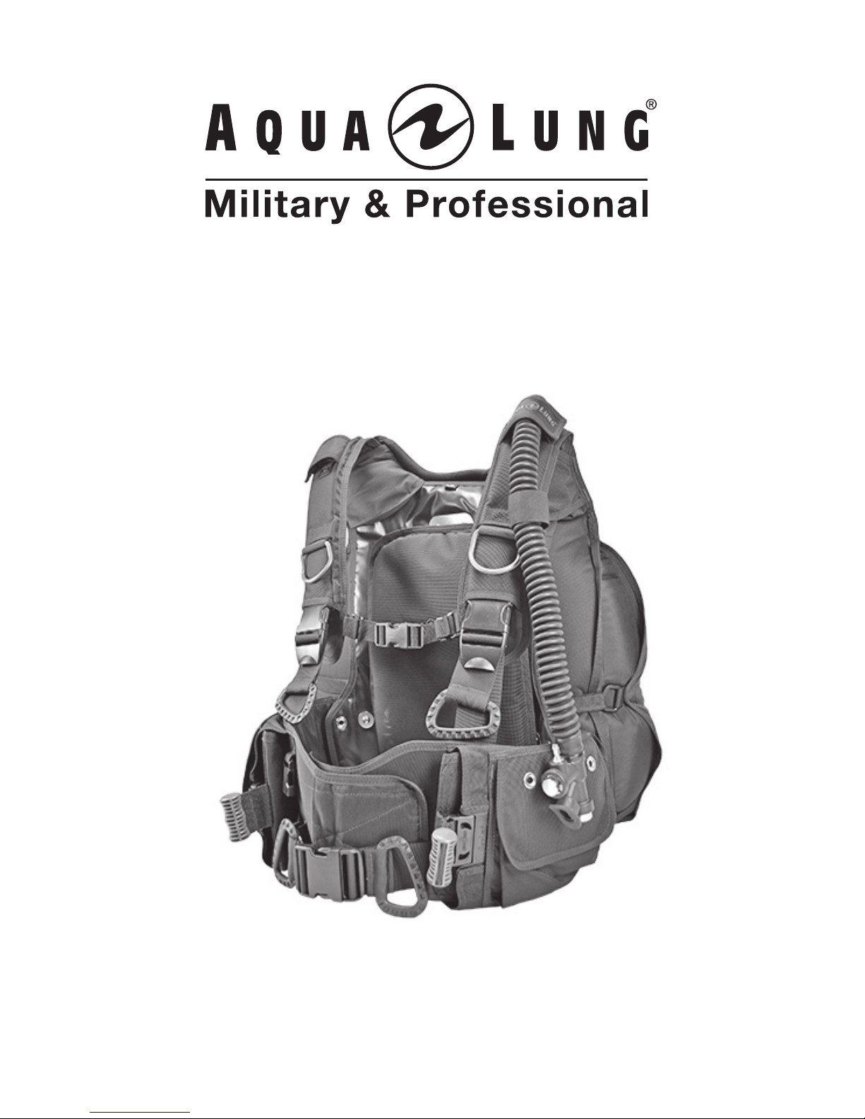
BC 1
Buoyancy Compensator
User's Manual
Rev. 03/16
Page 2
BC 1 User's Manual
2
COPYRIGHT NOTICE
This user's manual is copyrighted, all rights reserved. It may not, in whole or
in part, be copied, photocopied, reproduced, translated, or reduced to any
electronic medium or machine readable form with out prior consent in writing
from Aqua Lung America, Inc.
©2016 Aqua Lung International
BC 1 User’s Manual PN 18562
You can contact a Technical Advisor via e-mail at:
TRADEMARK NOTICE
Aqua Lung® is a registered trademark of
Aqua Lung America, Inc.
A NOTE is used to emphasize important points, tips and reminders.
A WARNING indicates a procedure or situation that, if not avoided,
could result in serious injury or death to the user.
A CAUTION indicates any situation or technique that could
cause damage to the product and could subsequently result in
injury to the user.
WARNINGS, CAUTIONS AND NOTES:
Pay special attention to information provided in Warnings, Cautions and Notes
that are accompanied by one of these symbols:
Page 3

3
General Precautions and Warnings .........................................4
BC 1 Components .....................................................................7
Product Description ..................................................................8
Basic Set-up ...............................................................................8
Donning and Adjustment Procedures ...................................16
Weight Integration Features ...................................................19
Ination Methods .....................................................................26
Deation Methods ...................................................................27
Buoyancy and Cylinder Capabilities .....................................29
Pre-Dive Inspection .................................................................31
Post-Dive Care and Maintenance ...........................................32
Dealer Inspection and Service ...............................................33
Warranty Information ..............................................................35
TABLE OF CONTENTS
Page 4

BC 1 User's Manual
4
This manual provides essential instruction for the proper tting, adjustment,
inspection and care of your new BC. Because Aqua Lung is utilizing patented
BC technology, it is very important to take the time to read these instructions in
order to understand and fully enjoy the features that are unique to your specic
model. Improper use of this BC could result in serious injury or death.
Before using this buoyancy compensator (BC), you must receive instruction
and certication in SCUBA diving and buoyancy control from a Military or
government operated diving school (or any recognized certication agency).
Use of SCUBA equipment by uncertied or untrained persons is dangerous
and can result in injury or death.
Read this owner’s manual completely before attempting to use your BC, and
become familiar with it rst in a controlled environment such as a swimming
pool, in order to weight yourself properly and to become comfortable with using
its many features and adjustments.
Before every dive, perform a complete pre-dive inspection according to the
procedure prescribed in this manual, to ensure that all components are func-
tioning properly and no signs of damage or leaks are present. If you nd that
your BC is not functioning properly or is damaged, remove it from service until
it can be repaired by an Authorized Aqua Lung Dealer or Distributor.
Your BC is not a lift bag. DO NOT use it to bring heavy objects to the surface.
Doing so may cause permanent damage to the BC, and could also result in
serious injury or death due to arterial gas embolism or decompression sickness.
In an emergency such as an out of air situation or uncontrolled descent, it is
important to remove and jettison weight immediately. DO NOT depend solely
on using your BC power inator to lift you to the surface.
In the event of an uncontrolled, rapid ascent, it is important to immediately
begin venting air from the BC. Continue venting air to slow your ascent rate if
neutral buoyancy cannot be reestablished.
DO NOT inhale from your oral inator. The BC may contain harmful contaminants
or gases, which could cause suffocation or injury.
Factory prescribed service for this BC must be performed at least once annually by
a factory trained technician who is employed by an Authorized Aqua Lung Dealer
or Distributor. Annual service consists of a complete overhaul of the power inator,
and a general air leak inspection of the bladder and valve connections.
Disassembly, repair, or lubrication must not be attempted by persons who are
not factory trained and authorized by Aqua Lung. Unauthorized service will
render the warranty null and void.
GENERAL PRECAUTIONS AND WARNINGS
Page 5
5
This BC is designed for use with compressed air or Nitrox/EAN (enriched air
nitrox) mixtures not exceeding 40% oxygen. Any use of gas mixtures with increased oxygen content or the addition of helium or other substances may cause
corrosion, deterioration and/or premature aging of the BC leading to component
failure of the metal and rubber parts. The component failures could lead to a
loss of buoyancy control and/or pressure integrity of the BC resulting in injury
or death. Non-standard breathing mixtures may also present a risk of re or
explosion. The use of Nitrox/EAN requires additional training. Failure to observe
this warning may result in injury or death. Use only nitrogen/oxygen mixtures
containing no more than 40% oxygen.
CE Conformity - This BC conforms to EN 1809: 2014.
It was controlled by the l’Institut National de Plongée Professionnelle,organisme
notié n°0078, entrée n°3 port de la pointe rouge 13008 Marseille -France.
TEMPERATURE LIMITATIONS: This BC should be exposed to temperatures no
lower than -4°F (-20°C) and no higher than 150°F (65°C).
WARNING: This is NOT a life jacket or a rescue device: It does not
guarantee a head-up position of the wearer at the surface. It is not
designed to provide face-up otation in all situations; therefore
it does not meet U.S. Coast Guard regulations for a life preserver
or personal otation device (PFD). If you become unconscious in
the water without a buddy present to immediately give assistance,
you may suffer serious injury or death from drowning.
Page 6
BC 1 User's Manual
6
For this reason, it is important to always dive with and maintain close proximity
to your buddy at all times. Do not depend on any otation device to hold your
face above the surface in the event that you are rendered unconscious in the
water while diving.
If you have any questions regarding your Buoyancy Compensator or
these instructions, please contact your Authorized Aqua Lung Dealer
or Distributor. Distributor information is available on the Aqua Lung
website at: www.aqualung.com/militaryandprofessional
WARNING: Although this manual provides some basic guidelines for
certain buoyancy control techniques, it is not a substitute for training from a professional diving instructor. Failure to weight yourself
properly may create a hazardous condition that could lead to serious
injury or death. If you are unsure how to weight yourself in order to
achieve optimum buoyancy underwater and on the surface, do not
dive until you have obtained the necessary instruction from your
diving instructor or an Authorized Aqua Lung Dealer or Distributor.
Your buoyancy compensator is primarily designed to help you maintain neutral
buoyancy while in a comfortably balanced, face-down swimming position under
water. It is also designed to provide you with otation so that you can rest on the
surface, but it is not designed to function as a life preserver or personal otation
device (PFD). In order to meet U.S. Coast Guard regulations, a PFD must be
designed so that it automatically rights you to a face-up position and holds your
head out of the water on the surface. The design characteristics of a personal
otation device are different from those of a buoyancy compensator. The ability
of any otation device to oat you in a face-up position can also be affected by
other diving equipment you wear, including a cylinder, weight or exposure suit,
and whether it can be inated before you lose consciousness.
Page 7
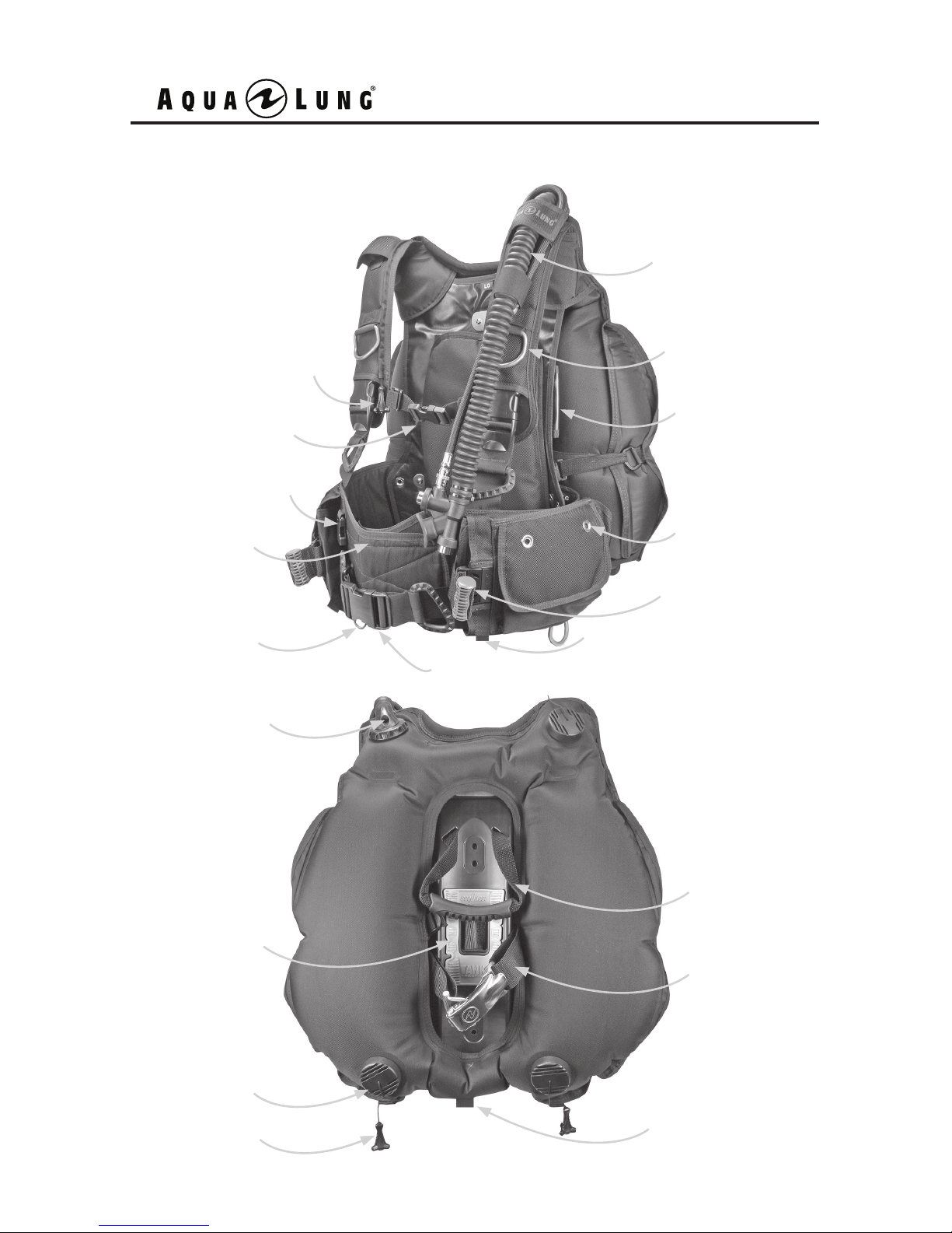
Pull Knob
Accessory Clip
Chest Strap
Inator
Knife Grommets (2)
on each pocket
Trim Pockets (2)
Cummerbund
Accessory D-rings (4)
Dump Valve (3)
GripLock Cylinder
Band
Carry Handle
Traction Pad
Pull Knob
Inator Dump
Valve
BC 1 COMPONENTS
John Line Ring
SureLock 1
Weight System
Waist Buckle
Front Crotch Strap
Loop (2)
Rear Crotch
Strap Loop
7
Page 8
BC 1 User's Manual
8
BASIC SETUP
Aqua Lung recommends that you take your buoyancy compensator, together
with your regulator, to your Authorized Aqua Lung Dealer or Distributor for the
installation of the MP inator hose and other accessories. The retailer can also
answer any questions you may have pertaining to the information in this manual.
If it is not possible to return the BC with your regulator to a Authorized Aqua
Lung Dealer or Distributor, you may install the MP quick disconnect inator hose
by carefully performing the steps in the following procedure.
NOTE: The terms “Hook & Loop” are used throughout this manual. Hook
& Loop is commonly known as Velcro®, which is a trademarked brand of
hook & loop. Some of the BC components have hook & loop attachments.
PRODUCT DESCRIPTION
BC 1 is a modular design buoyancy compensator consisting of three major
components: harness, bladder and waistband w/ integrated weight system. Its
rugged design makes it a perfect choice for military or public safety diving ap-
plications. Some specic features include stainless steel hardware, reinforced
backpack, adjustable waistband, knife grommets, crotch strap attachment points,
john line ring and removable backpad.
The doughnut shaped bladder allows for air ow migration and improved stability. External retraction bands reduce the divers in-water prole by keeping the
bladder close to the body. The removable bladder can be swapped out when a
replacement is needed.
Page 9
9
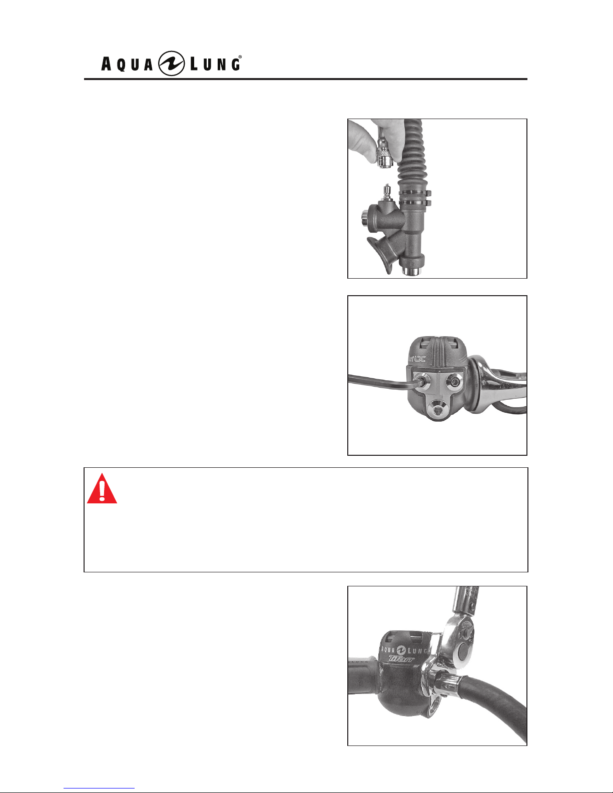
Attaching the MP Hose to the First Stage
1. Remove the inator hose from the power
inator body by gripping the grooved sleeve
over the quick disconnect coupling with your
thumb and forenger. Slide the sleeve back.
2. Remove the port plug from a MP port
on the regulator using the appropriate size
wrench.
3. Check to ensure the o-ring is present
and in good condition. Screw the threaded
end of the hose into the port and tighten
to 40 in-lbs (46 kg-cm) with a 9/16” torque
wrench.
WARNING: DO NOT connect the inator hose to a high pressure (HP)
port (greater than 200 psi / 14 bar). This may cause the hose to burst
when pressurized, which can result in serious injury. If you are unsure
which regulator port is medium pressure (MP) or high pressure (HP),
consult your regulator owner’s manual or your Authorized Aqua Lung
Dealer or Distributor before attaching the hose.
Page 10
BC 1 User's Manual
10
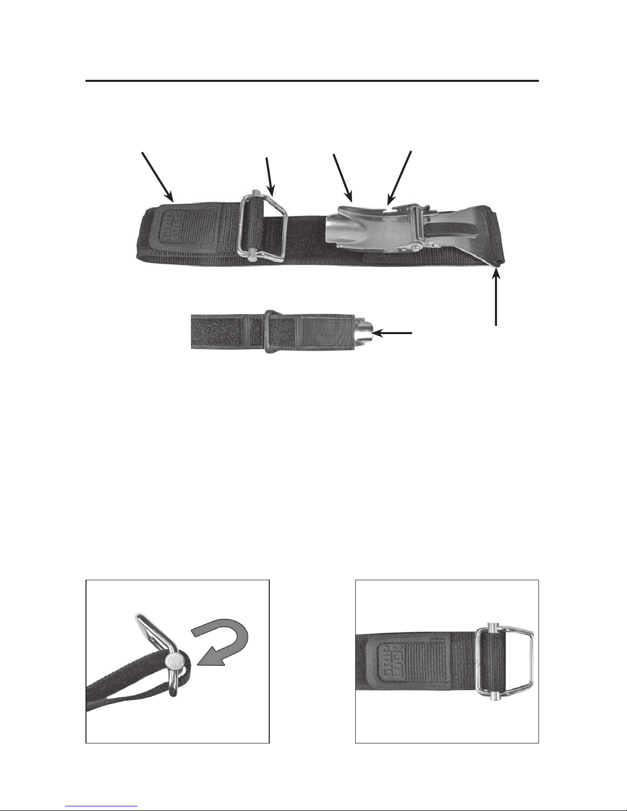
Threading the GripLock™ Cylinder Band
If the GripLock cylinder band has been removed from the bail, re-thread using
the following procedure:
Insert the open end of the cylinder band into the large opening of the bail,
around the slide bar and out of the small opening of the bail. Secure the hook
and loop on the band to hold the bail in place.
GripLock™ Cylinder Band Components
Macro Adjustment
Micro Adjustment
Bail
Lever
Bail Slot
Page 11
11
Adjusting the GripLock™ Cylinder Band
NOTE: The GripLock cylinder band adjusts for all standard cylinder
diameters and is ready for use with an aluminum 80 cf (7.25 inch /
184 mm) cylinder when the BC leaves the factory.
WARNING: The BC must be completely deated of air before adjusting
the GripLock cylinder band. Failure to do so may result in the cylinder
slipping during the course of a dive.
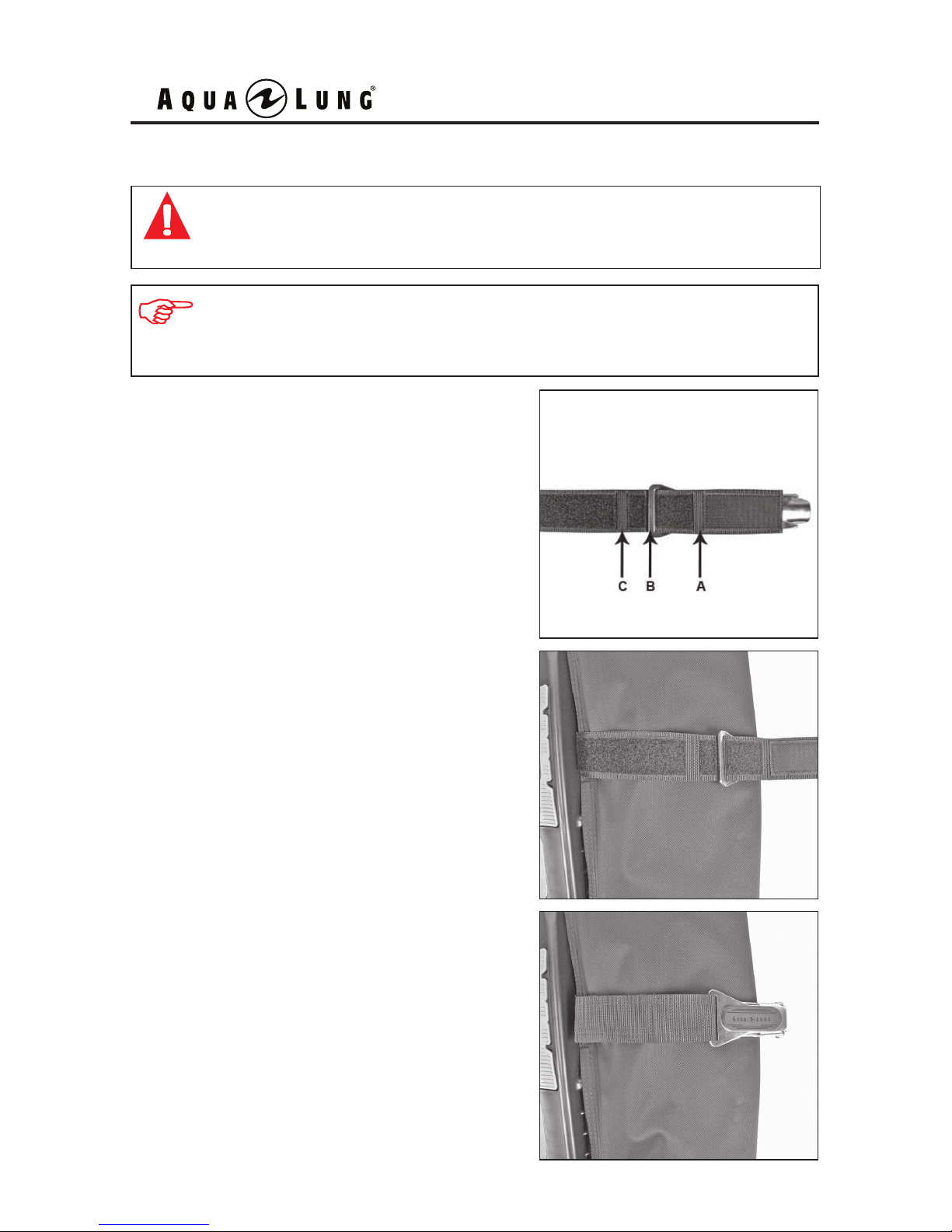
2. Adjust the macro adjustment for the
proper cylinder size.
3. Secure the hook and loop after cylinder
size is selected.
1. There are three macro settings for
cylinder size:
A. Larger cylinder
B. Al 80 cf (7.25 in/184 mm)
C. Smaller cylinder
Page 12
BC 1 User's Manual
12
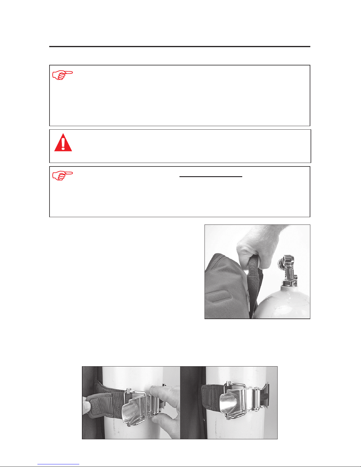
1. Make sure the cylinder valve air outlet
is facing the back of the BC.
2. For optimum cylinder retention, center the GripLock buckle assembly on the
curve of the cylinder. Connect the bail into the bail slot of the lever. Hold the lever
and pull the webbing to tighten the micro adjustment. Secure the hook and loop
webbing on the micro adjustment.
Securing the GripLock™ Cylinder Band
NOTE: Pull the micro adjustment only until it is snug against the cylinder.
If the lever is difcult to close, the micro adjustment is too tight. Loosen the
micro adjustment and close lever to secure GripLock band to cylinder. If it is
difcult to remove the GripLock band from the cylinder, this is an indicator
that the micro adjustment was too tight when installed.
NOTE: There is no need to wet the GripLock cylinder band prior to
securing it to the cylinder. When properly adjusted, the cylinder band
will retain it’s tension. If adjustment is necessary for a larger or smaller
size cylinder (pre-set for use on an aluminum 80 cf cylinder 7.25 inch /
184 mm), follow the procedure in the section: Adjusting the GripLock
Cylinder Band.
WARNING: Check that the macro adjustment is set for the appropriate
size cylinder. Failure to do so may result in the cylinder slipping during
the course of a dive.
Page 13
13
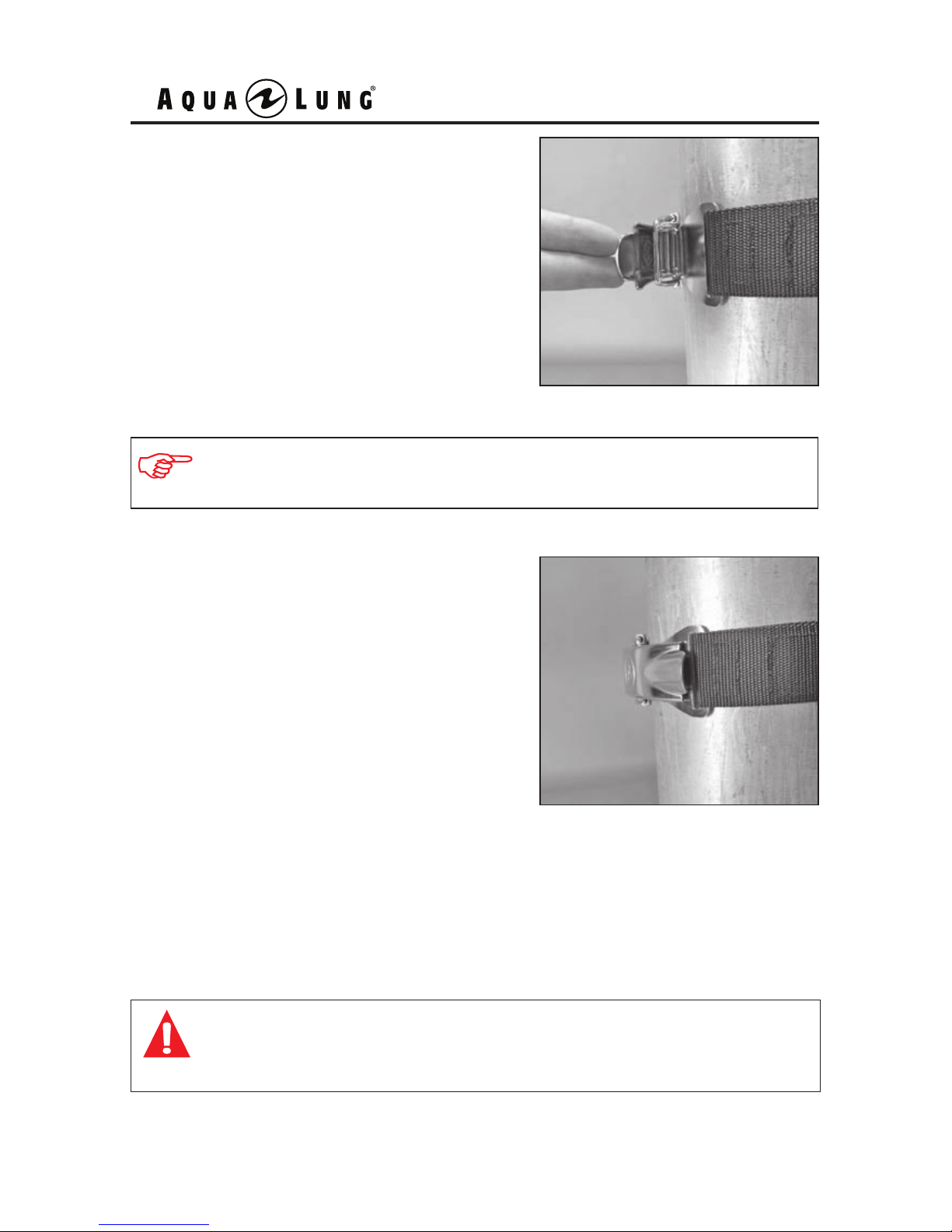
3. Push the lever forward until it stops in
the pre-locked position.
4. Push the lever down into the locked
position. Verify the lever is secured in the
locked position. Once the cylinder band
is set up, further adjustment is typically not
needed.
5. Check that the cylinder band is secure by pulling on the band while holding
down the cylinder at the valve. If the cylinder band moves, it is too loose. Check
that the macro adjustment is set for the correct size cylinder. Repeat steps 1-4 to
tighten and secure the cylinder band.
WARNING: Verify the tension of the cylinder band prior to every
dive. Failure to do so may result in the cylinder slipping during
the course of a dive.
NOTE: The pre-locked position ensures your ngers do not get
caught in the lever.
Page 14
TOP VIEW
BC 1 User's Manual
14
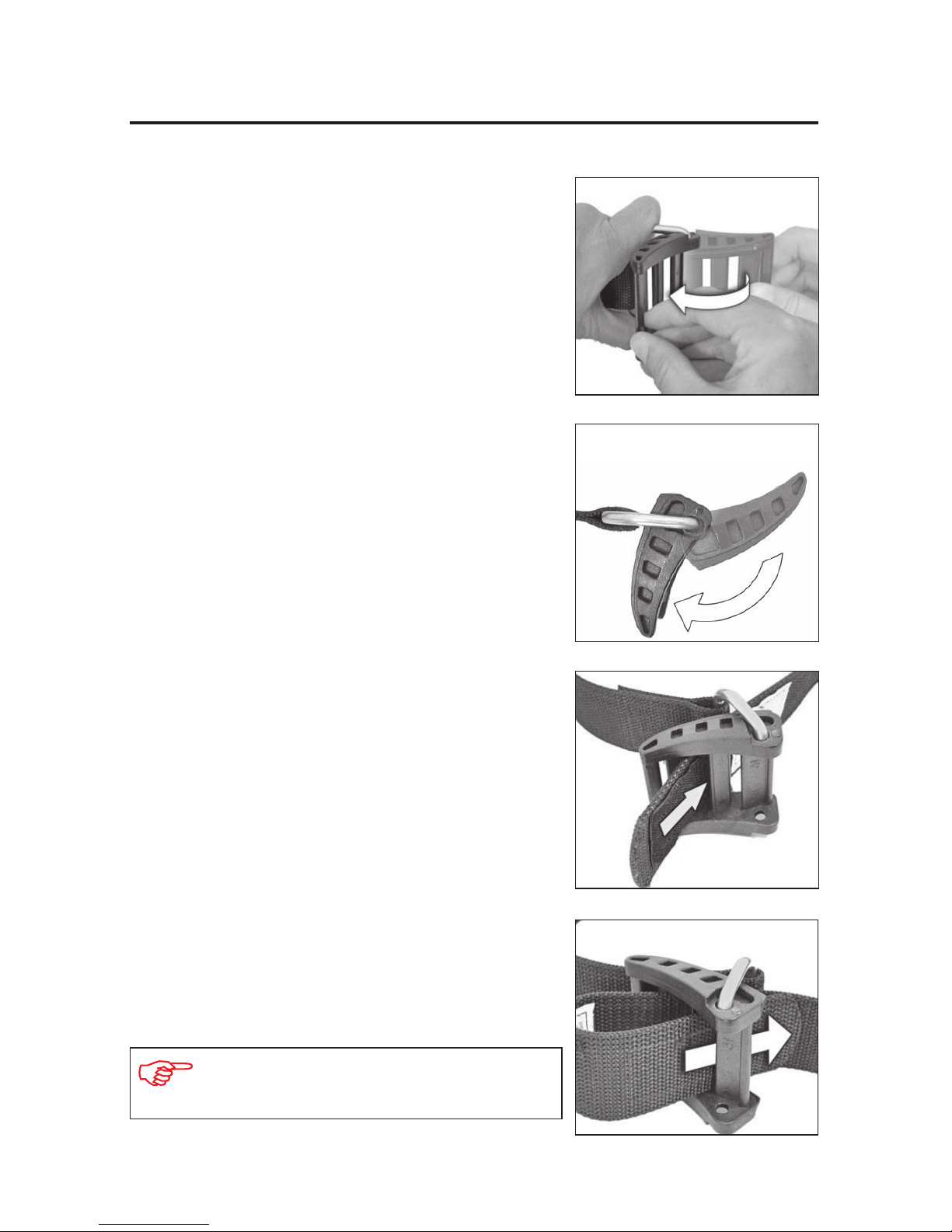
Threading the Cam Buckle
1. Firmly grasp the metal D-ring with your
left hand.
2. While rmly holding the metal D-ring,
rotate the buckle back towards the webbing.
The buckle should form an angle with the
metal D-ring as shown in the top view.
3. Insert band through the metal D-ring, then
through the middle slot of the buckle.
4. Insert band through the inside slot of the
buckle.
NOTE: The threading instructions are
imprinted on the plastic cam buckle.
Page 15
15
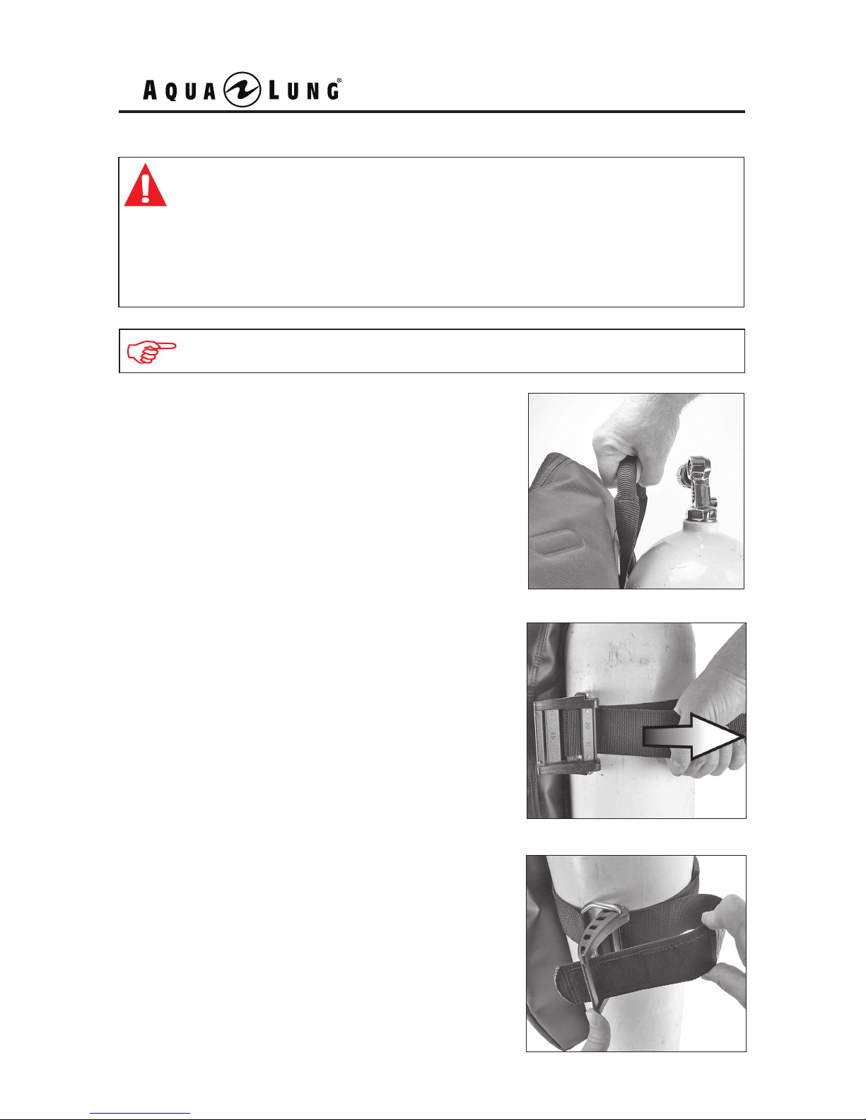
1. Slide the cylinder band over the cylinder
so that the BC is at the desired position in
relation to the cylinder valve. Make sure the
cylinder valve air outlet is facing the back of
the BC.
WARNING: The cylinder band will initially stretch as it becomes
wet. Always wet the band before making the nal adjustment;
apply enough tension to ensure that the cylinder is completely
secure. Test this connection before every dive. If the cylinder
slips free from the BC during the dive, you may loose your air
supply, which could lead to serious injury or death.
Securing the Band to the Cylinder
2. While holding the cylinder secure, pull the
free end of the cylinder band webbing until
there is a very tight t between the cylinder
plate and the cylinder.
3. Close the buckle halfway to hold the
cylinder band taut, and thread the free end
of the band through the open slot in the end
of the buckle.
NOTE: Universal cylinder bands adjust for all standard cylinder diameters.
Page 16
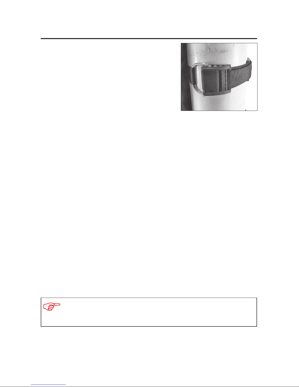
5. Check the cylinder band is secure by pulling
on the band while holding down the cylinder
at the valve. If the cylinder band moves, it is
too loose. Repeat steps 1-4.
4. Pull the cam buckle closed so that it lies
at against the cylinder. Secure the end of the
cylinder band with the hook & loop attachment.
BC 1 User's Manual
16
DONNING AND ADJUSTMENT PROCEDURES
8. Fully inate the BC and check there is no restriction of normal breathing
and movement.
9. If necessary, re-adjust the BC straps as needed.
NOTE: Adjusting the shoulder straps too tightly will transfer the cylinder
weight from the hips to the shoulders, restricting your arm movement
and decreasing comfort.
1. Remove the weight pouches from the BC.
2. Disconnect the chest strap, waist buckle and cummerbund.
3. Ensure that the quick release buckles on both torso straps are securely
fastened. While rmly holding the torso strap where it connects to the
BC lobe, fully extend each torso strap to its maximum length by pushing
straight up on the slide buckle.
4. While your dive buddy lifts and holds the BC/cylinder behind you, place
your arms through the BC torso straps as if you were putting on a jacket.
5. While your buddy continues to hold the cylinder, connect the cummerbund
and waist buckle. The weight of the cylinder should rest on the lumbar region
(lower part) of your back.
6. Connect the chest strap buckle. Pull on the free end of the strap to tighten.
The chest strap should feel comfortable across the chest; it should not be
overtightened so that it feels restrictive.
7. After your buddy has released the cylinder and the BC feels comfortably
supported on your hips and shoulders, bend forward at the waist and adjust
the torso straps to a comfortable length by pulling rmly downward on the
torso strap d-rings.
Page 17
17
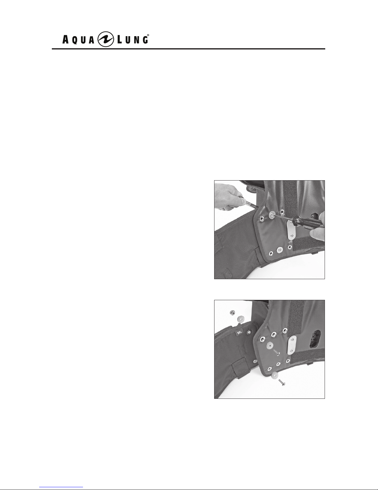
Adjusting the Waistband Length - Nut and Bolt System
Each side of the BC waistband is connected to the harness with two nut & bolt
and washers combinations (all hardware is stainless steel). There are three
positions that allow you to lengthen or shorten the waistband, with the outer
grommets being the longest setting. If necessary, the waistband can easily be
remounted onto one of three grommet attachment points by performing the
following procedure:
1. Disconnect the chest strap buckle, shoulder strap buckles, waist buckle and
cummerbund.
2. To remove the bolts which fasten each
section to the harness, hold the nut with
a 3/8” box wrench and unscrew the bolt
with a medium sized Phillips screwdriver.
3. Align the grommet holes on the waistband with the grommet holes on the harness. Place a washer onto the bolt. Insert
the bolt through the grommet holes on the
harness and waistband. Place a washer
onto the bolt from behind the waistband,
followed by the nut. Hold the nut securely
with a 3/8” box wrench and tighten the bolt
with a medium size Phillips screwdriver.
Repeat the process for the remaining
hardware.
4. Don the BC over your exposure suit to
check the t.
Page 18
BC 1 User's Manual
18
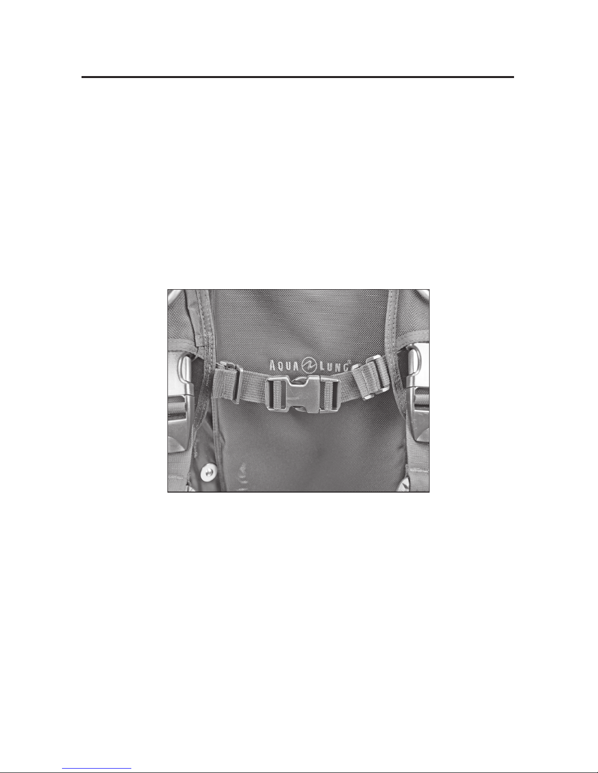
The chest strap ts across your sternum and keeps the shoulder straps
from slipping to the sides, ensuring a comfortable and secure t. Before
donning the BC, loosen and disconnect the chest strap. After donning the
BC, connect the chest strap and tighten by pulling on the free ends of the
straps. The chest strap should feel comfortable across the chest; it should
not be overtightened so that it feels restrictive. Once the shoulder straps
are in position, adjust the shoulder strap length by pulling down on the
d-rings until the BC ts comfortably. Become familiar with the adjustment of
this strap so that you can perform this adjustment in the water if necessary.
Removable Chest Strap
The chest strap on your BC is removable. To remove the chest strap, unweave
the straps from the male and female parts of the chest buckle. For each strap,
pull the free end through the plastic rings connected to the strap. Pull the strap
through the plastic rings that are connected to the BC.
Adjusting the Chest Strap
Crotch Strap (optional)
An optional crotch strap (PN 427038) can be attached to the three crotch strap
attachment points sewn into BC (two front and one rear). The addition of a crotch
strap can prevent the BC from riding up on diver, providing a more secure t.
Page 19
Hook and Loop PouchSureLock 1 Pouch
19
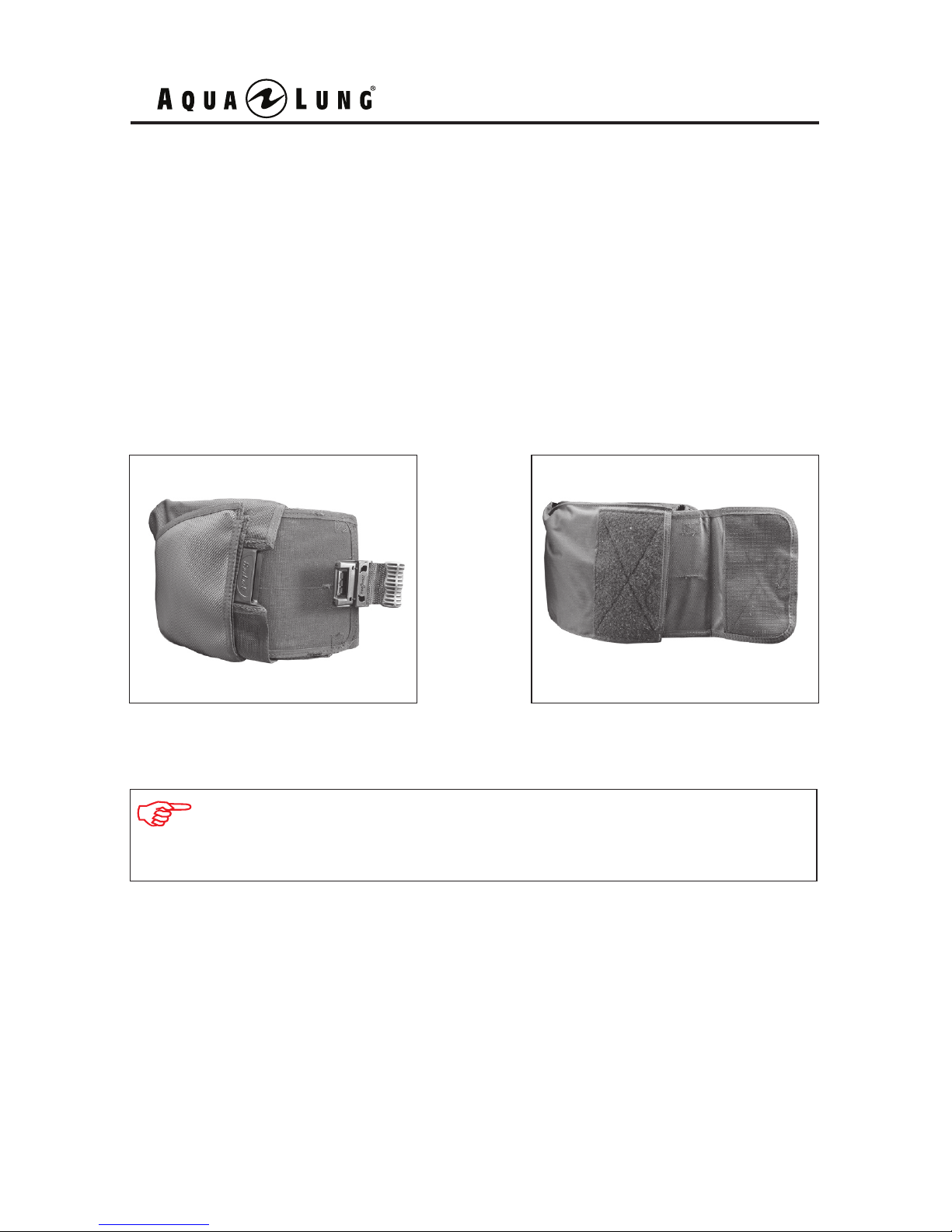
Your BC comes equipped with either a Hook and Loop or SureLock 1 Integrated
Weight System. The SureLock 1 weight pouches are secured with a mechanical
locking mechanism. The Hook and Loop weight pouches are secured with hook
material on the pouches to loop material on the BC pockets. Either weight system
supplements or replaces a conventional weight belt. This unique feature allows you
to quickly jettison either one or both weight pouches in the event of an emergency,
thereby maintaining better control over your rate of ascent. The weight pouches can
be easily reloaded into the BC pockets while you are wearing the BC.
NOTE: It is very important to read the following instructions and become
thoroughly familiar with the correct methods for installing and releasing
weight before you dive with your BC.
WEIGHT INTEGRATION FEATURES
Page 20
BC 1 User's Manual
20
NOTE: Your BC may not be able to oat by itself on the surface if your
BC is loaded with weight at or near its maximum buoyancy. In water, the
weight of cylinders and other equipment may contribute to the negative
buoyancy of your full set of SCUBA equipment.
WARNING: The lift capacity may not exceed the weight pouch carry
capacity (See Buoyancy and Cylinder Capabilities). The negative
buoyancy of the weight plus the negative buoyancy of the cylinder
(when full), should not exceed the BC’s positive buoyancy. The
inability to achieve neutral buoyancy while at depth or positive
buoyancy on the surface may lead to a hazardous situation that
could lead to serious injury or death.
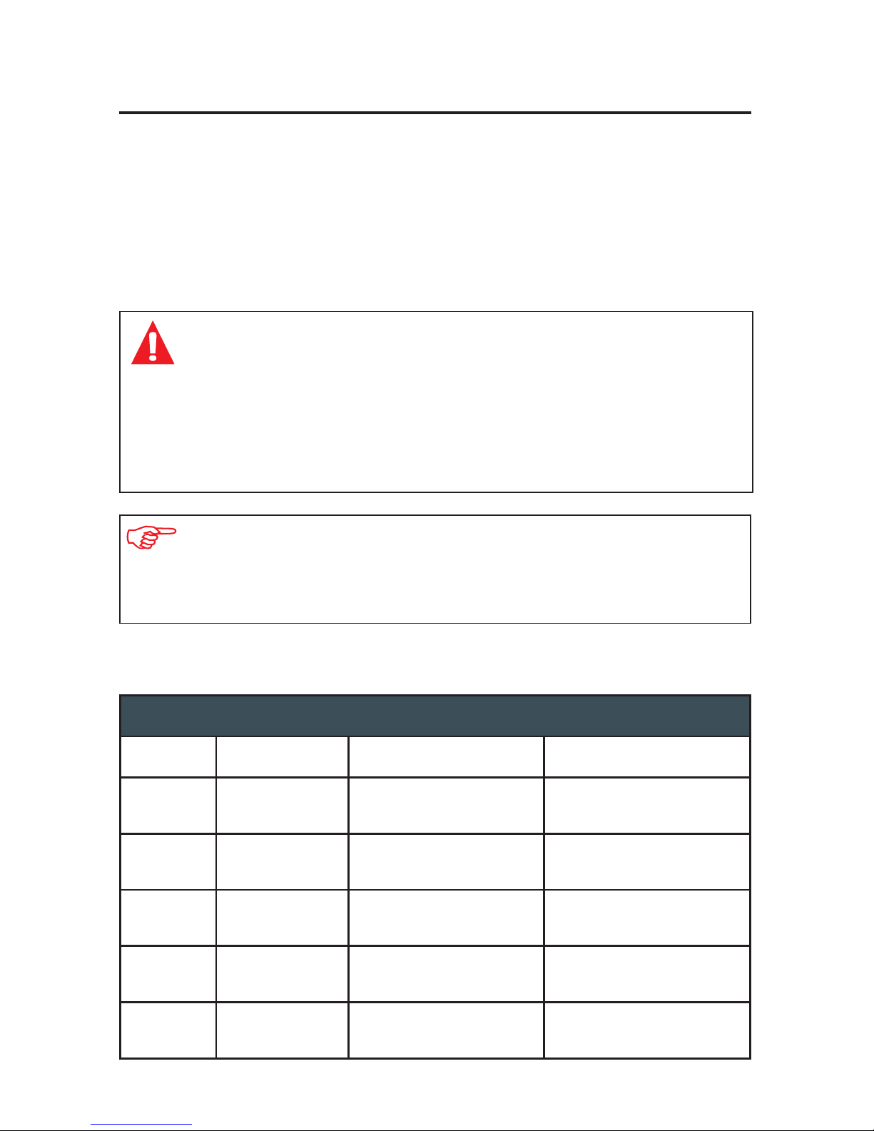
Weight Capacity Chart
BC 1
BC Size Trim Weight Releasable Weight Weight Pocket Type
SM 5 lb/2.5 kg X 2 32 lb/14.5 kg 16 lb/7.25 kg X 2
MD 5 lb/2.5 kg X 2 32 lb/14.5 kg 16 lb/7.25 kg X 2
ML 5 lb/2.5 kg X 2 32 lb/14.5 kg 16 lb/7.25 kg X 2
LG 5 lb/2.5 kg X 2 32 lb/14.5 kg 16 lb/7.25 kg X 2
XL 5 lb/2.5 kg X 2 32 lb/14.5 kg 16 lb/7.25 kg X 2
Maximum Weight Capacity
The Hook and Loop or SureLock 1 weight system features two interchangeable
weight pouches which can be lled with either block weights or “soft weight”
(pouches containing lead shot), in increments of 4 pounds or less. For ease
of operation, low-prole block weights are strongly recommended. Refer to the
Weight Capacity Chart for maximum weight capacity.
Page 21
4
C
A
B
Top Top Top
Top
Top Top Top
21
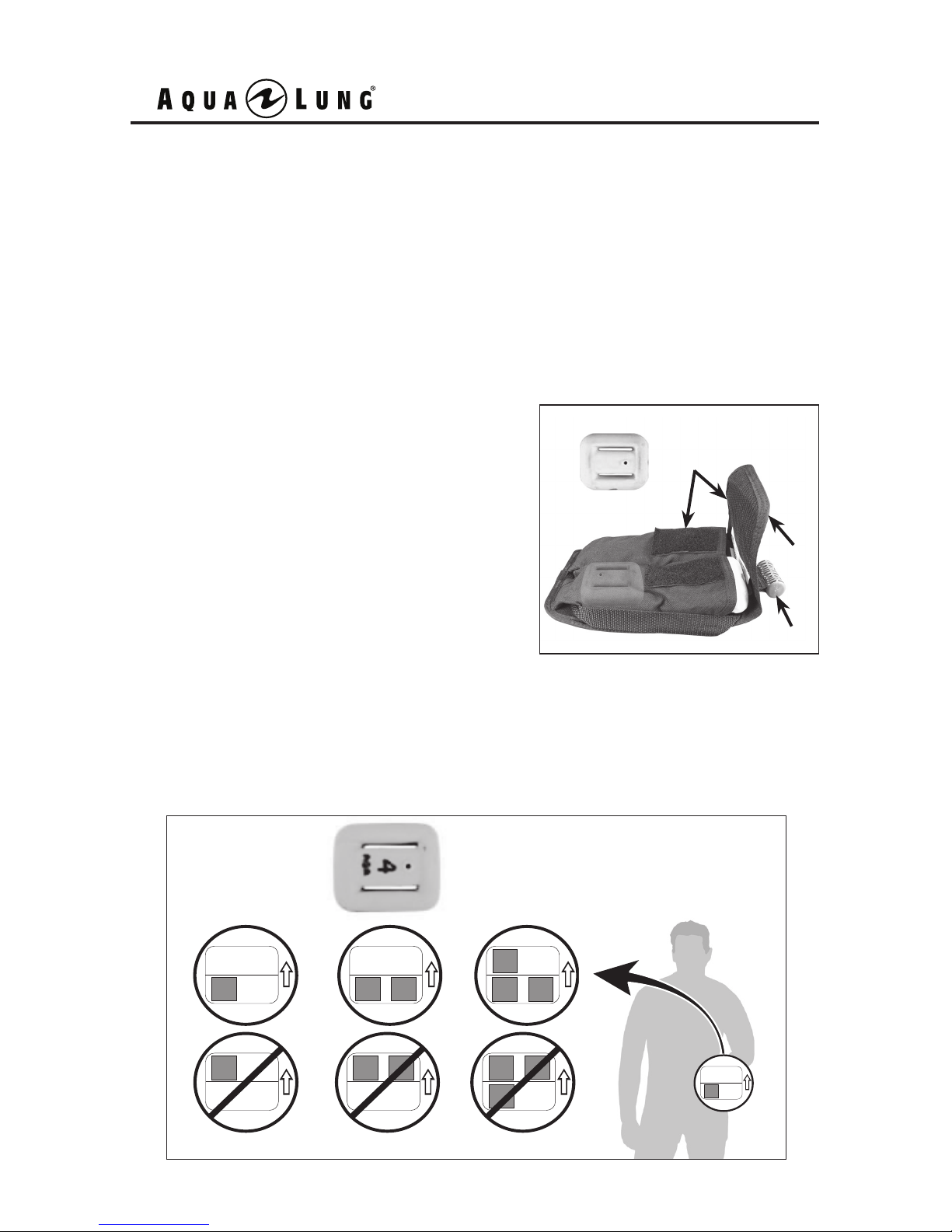
Loading Block Weight into the Weight Pouches
The amount of weight each pouch will hold and the process for loading the pouch
is the same for either Hook and Loop or SureLock 1 version pouches. Aqua
Lung recommends that each pouch is loaded with equal amounts of weight for
optimum balance, preventing the tendency to roll to one side during the dive.
Also, it is strongly recommended that each weight pouch is fully loaded with four
separate block weights. For example, if you want to load a 16 lb. pouch with 16
pounds of weight, use four separate 4 pound blocks.
Lift up each pouch’s ap (A), and lay it
back over the handle (B). While holding
the pouch fully open, insert the weight
(horizontally) into the upper and lower
weight compartments, then close the ap.
When each pouch has been loaded with
weight, rmly run your hand over the aps
to securely fasten the hook & loop (C).
Aqua Lung recommends that the pouches be completely lled with four separate
block weights (two per compartment); however, if you need to partially ll the
pouch, load the bottom compartment rst. Use the diagram (below) for proper
weight placement.
Page 22
A
B
BC 1 User's Manual
22
NOTE: Some weight pouches are specially pre-formed to t the contour
of your waist. Do not attempt to bend or straighten a pre-formed pouch.
CAUTION: Aqua Lung strongly recommends that you do not
attempt to don your BC when it is fully loaded with weight. You
may otherwise risk injury due to muscle strain or a temporary
loss of balance.
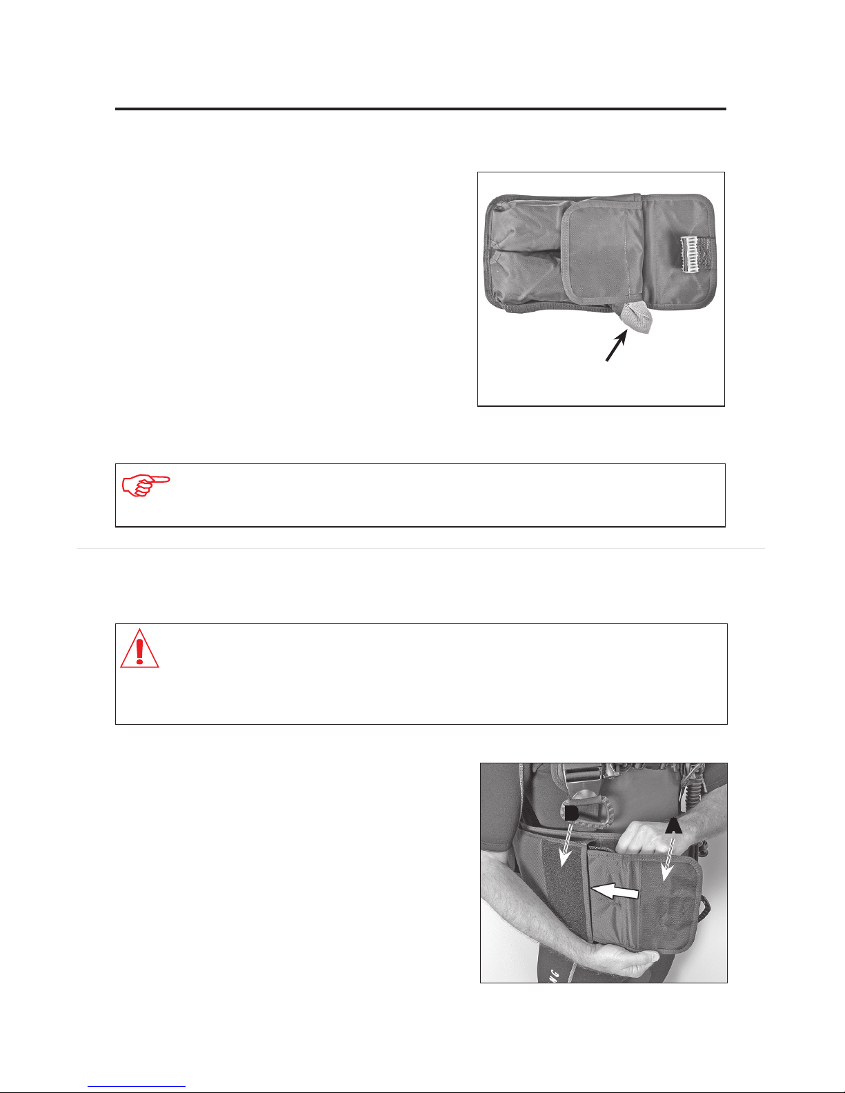
Installing the Hook and Loop Weight Pouches
Loading Soft Weight into the Weight Pouches
Aqua Lung recommends block weights
be used in the weight pouches for the
best t and ease of insertion. Soft
weights may be used, but it is critical
that the weights be loaded and secured
correctly. The procedure for loading soft
weights is the same as block weights,
but it is important to ensure the soft
weights are completely tted into the
weight pouch. This will ensure that the
weight pouch is properly engaged and
secured in place.
The hook and loop pouches are installed
with the smooth panel facing outward.
To install either pouch, slide the closed
end of the pouch into the opening of the
pocket. Fold the retaining ap (A) over
the loop material (B) and rmly run your
hand over the ap to securely seal the
hook and loop of the weight system.
soft weight should not be exposed
outside of weight pouch
Page 23
B
A
23
CAUTION: Aqua Lung strongly recommends that you do not
attempt to don your BC when it is fully loaded with weight. You
may otherwise risk injury due to muscle strain or a temporary
loss of balance.
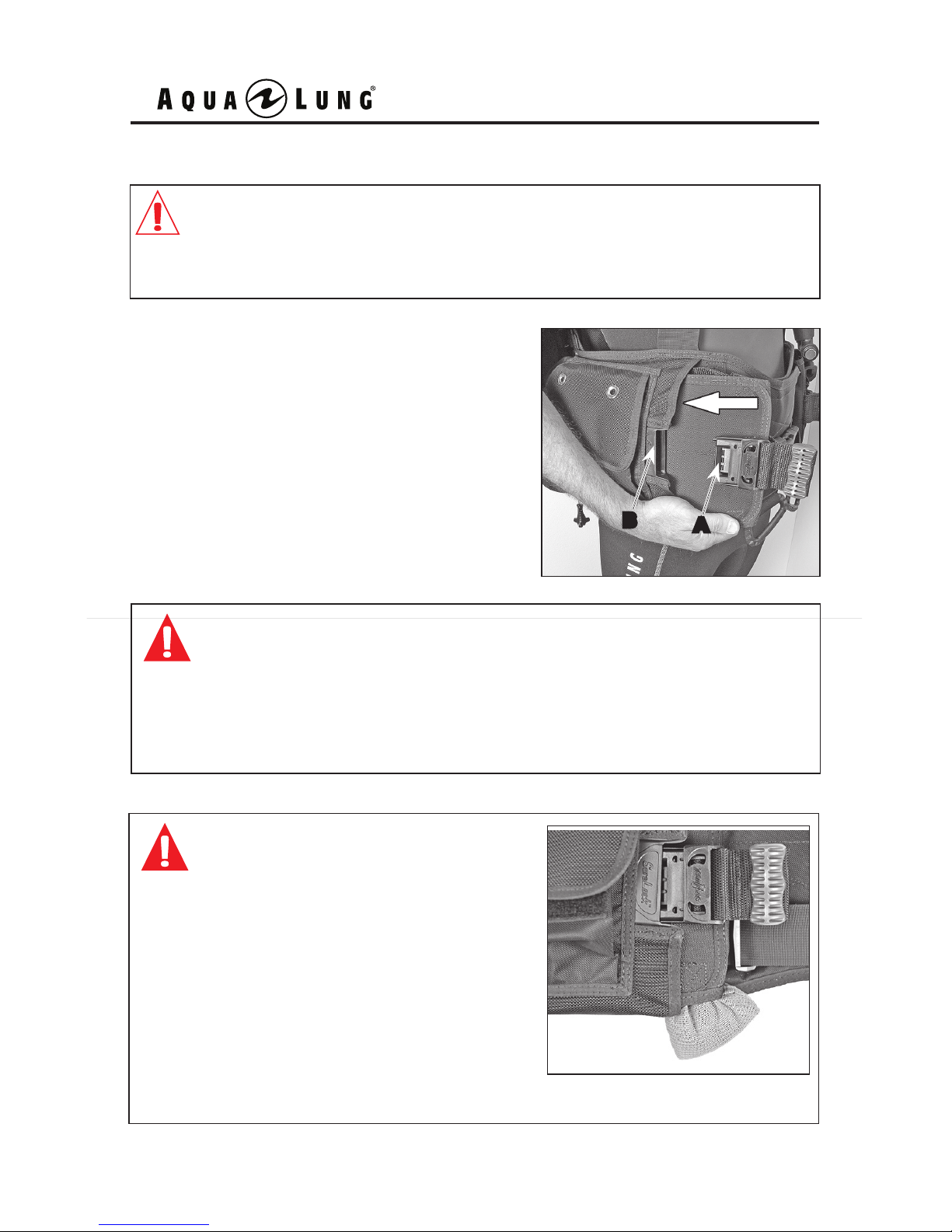
Installing the SureLock 1™ Weight Pouches
The SureLock 1 pouches are installed with
the smooth panel facing outward (pouch
ap facing toward the BC). To install either
pouch, slide the closed end of the pouch into
the opening of the pocket. Insert the male
portion of the SureLock 1 buckle (A) into the
female receptacle (B) on the BC until you
can hear and feel it "click" into place.
WARNING: Before every dive, it is important to make sure each
weight pouch is secured, in order to prevent the pouches from
falling out. Involuntary release of both weight pouches underwater
can cause a sudden increase in buoyancy causing a rapid ascent,
which could lead to serious injury or death due to arterial gas
embolism, decompression sickness, or drowning.
WARNING: Ensure the soft weight is
inserted all the way into the pouch.
If any portion of the soft weight is
protruding out of the weight pouch,
it can prevent the pouch from being
properly secured. Involuntary release
of both weight pouches underwater can
cause a sudden increase in buoyancy
causing a rapid ascent, which could
lead to serious injury or death due to
arterial gas embolism, decompression
sickness, or drowning.
Page 24
BC 1 User's Manual
24
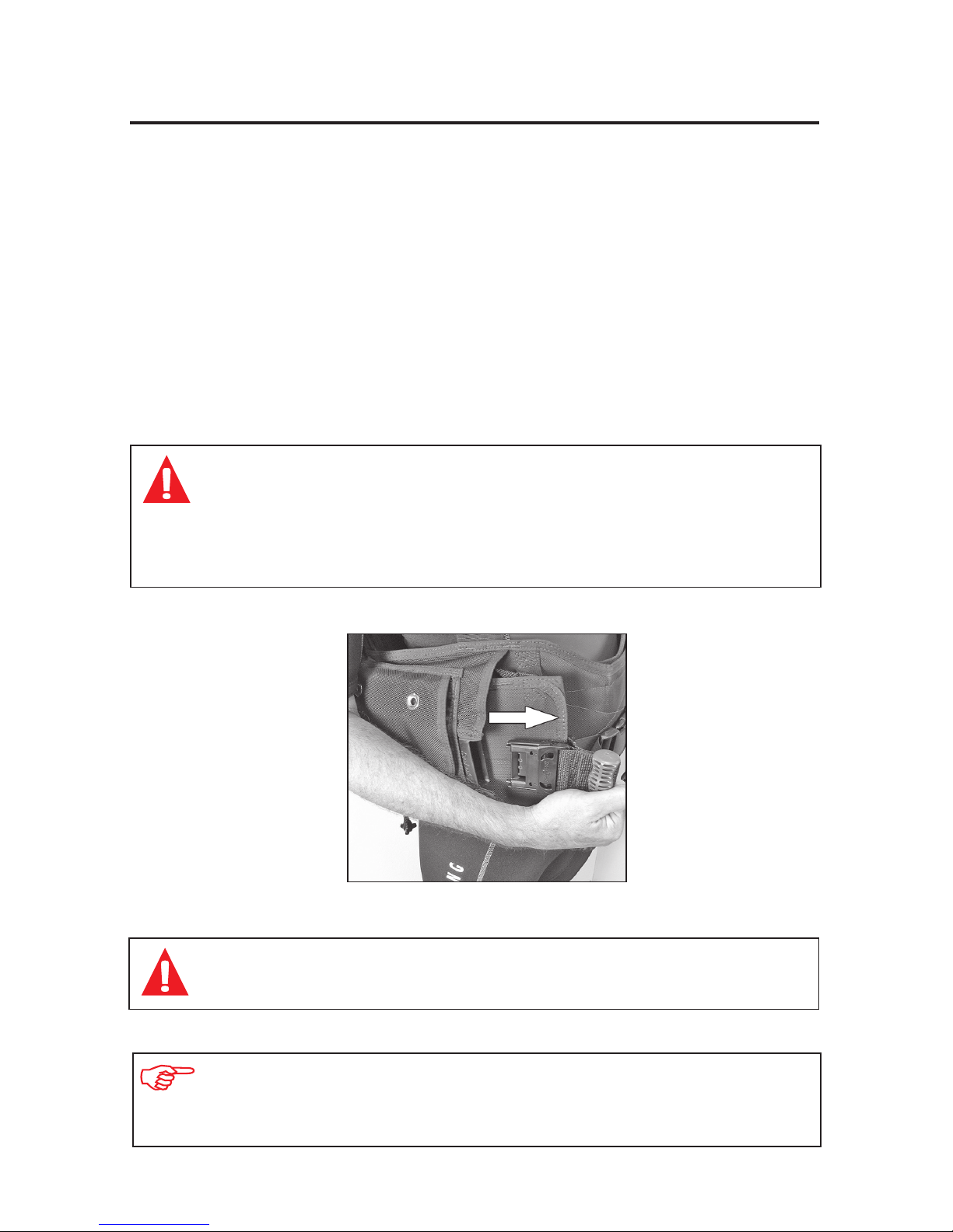
Releasing the Weight Pouches
Unlike a weight belt, which has only one release mechanism, each weight pouch is
connected to the BC independently of the other and must be released separately.
This provides you with the option of being able to jettison one pouch at a time,
thereby maintaining better control of your ascent rate in an emergency.
In the event that you need to jettison weight, simply pull the release handle of
each pouch towards the center of the waistband. When the pouch is completely
disengaged from its holster, hold it out and away from your body before dropping it.
Weight pouch release procedures are the same for both Hook and Loop and
SureLock 1 weight systems.
WARNING: Ensure that your weight pouches are not obstructed
by any straps, lines or hoses. DO NOT add weight to the BC
pockets, as this may interfere with the removal of the pouches
in an emergency. Failure to ditch weight in an emergency may
lead to serious injury or death due to drowning.
NOTE: In addition to becoming familiar with the weight system yourself,
it is very important to explain its function to your dive buddy so they
are equally familiar with it.
WARNING: To avoid injuring other divers, always look below you
before dropping weight.
Page 25
25
Non-Releasable Weight
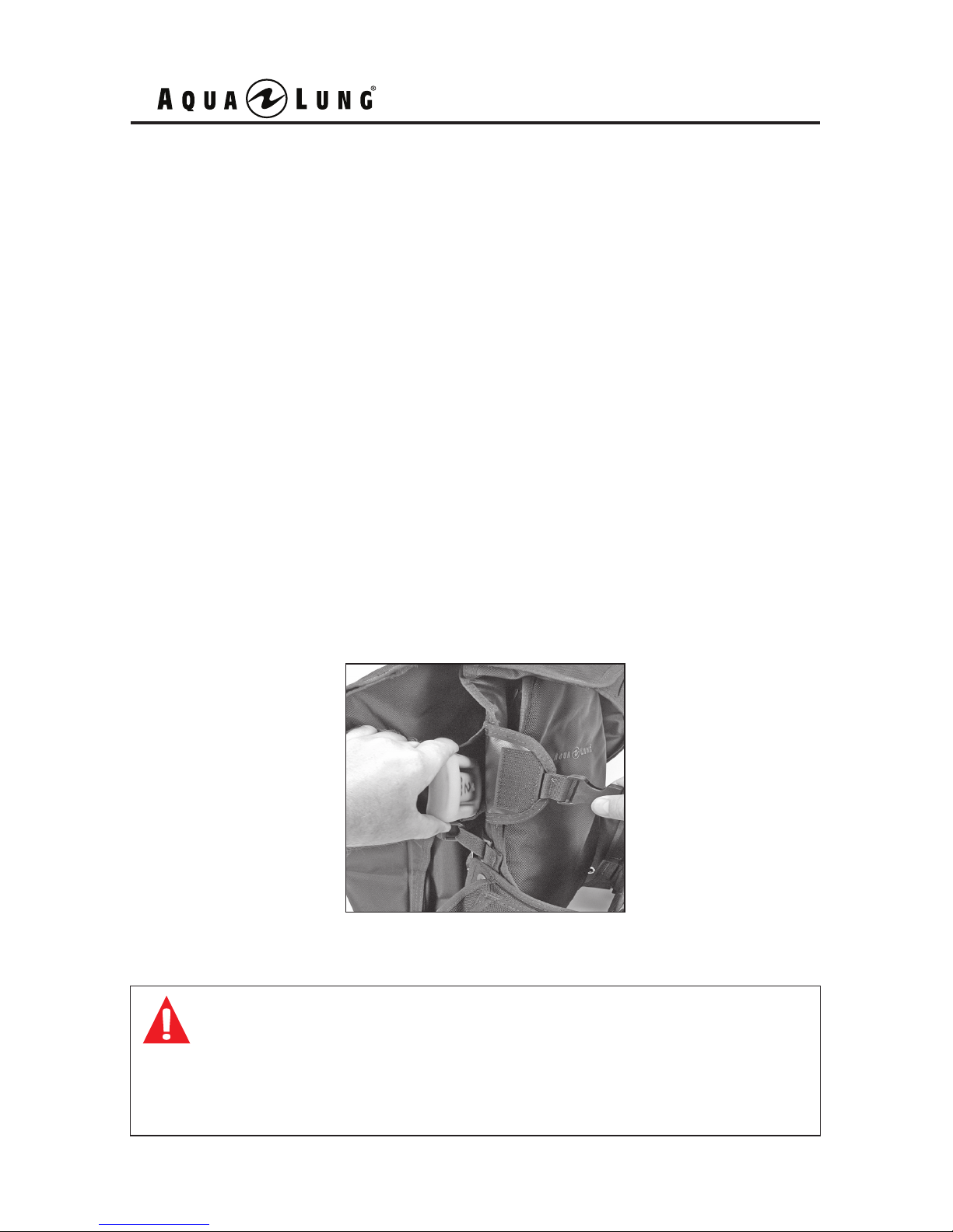
To supplement the releasable weight, your BC is designed to carry non-releasable
(trim) weight in two xed pocket locations.
To install weight into the non-releasable weight pockets, simply disconnect the
ap buckle, slide in the block weight, fold the ap over the pocket, and reconnect
the buckle. Weight should be added to the non-release (trim) pockets after the
BC has been secured to the cylinder.
The non-releasable weight pockets are designed to hold single rectangular
block weights. To avoid accidental loss of weight, Aqua Lung strongly advises
against using small bullet-shaped weights and soft weight.
Refer to the Weight Capacity Chart for maximum non-releasable weight capacity.
Because the weight is non-releasable, it must not be used as your primary source
of ballast. After lling the xed pockets with weight, it is extremely important to
check your buoyancy in the water while wearing the BC attached to a fully charged
cylinder and your exposure suit. While standing in chest deep water, deate the
BC completely and check to ensure that you can easily achieve positive buoyancy
by jettisoning your releasable weight.
WARNING: The non-releasable weight pockets are intended strictly
for containing non-releasable weight, used in addition to releasable
weight. Do not ll either pocket with weight unless you are certain
you can achieve positive buoyancy at depth by releasing your
weight pouches or weight belt while your BC is completely deated.
Page 26
BC 1 User's Manual
26
INFLATION METHODS
D
C
E
B
A
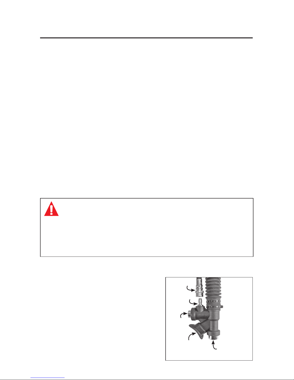
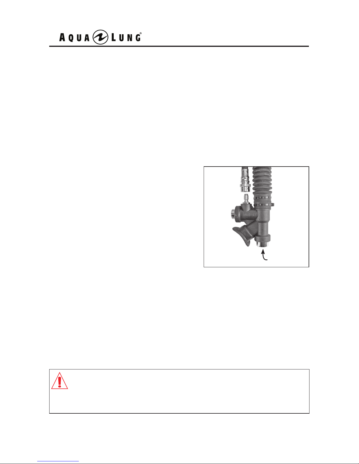
To orally inate your BC, place your lips
on the oral inator mouthpiece (E) and
exhale a small amount of air into the
mouthpiece to purge any water that may
still be in the housing. While continuing
to exhale into the mouthpiece, depress
the oral inator button (D) to inate the
BC. Immediately after exhaling, release
the oral inator button to prevent air from
escaping.
Oral Ination
For the power inator to operate, the medium pressure (MP) inator hose must
be connected. To connect the MP hose, grip the grooved sleeve at the connection
tting (A) with your thumb and forenger and slide the sleeve back. Place the
connection tting over the quick disconnect tting (B) on the inator and rmly
push inward while releasing the sleeve. Check to ensure that the MP hose is
securely attached. After the MP hose is attached to the power inator, pressurize
the rst stage regulator by slowly opening the cylinder valve.
To inate your BC with medium pressure air, depress the power inator button
(C). Do not hold the power inator button depressed continuously underwater,
as this could cause you to become excessively buoyant. Instead, depress the
power inator button in short bursts until you become neutrally buoyant.
Power Ination
The working pressure of the inator is as follows: 103 PSI (7 BAR) minimum 294 PSI (20 BAR) maximum.
WARNING: Do not rely on the power inator as the only means
to inate your BC. It is important to practice the technique of
orally inating your BC so that you are prepared for any type of
malfunction or out of air situation that could render the power
inator inoperable. You may otherwise be unable to achieve
positive buoyancy in an emergency, which could lead to serious
injury or death.
Secure the power inator in place with the hook and loop attachment on the BC.
Page 27
D
27
DEFLATION METHODS
CAUTION: It is not necessary to use excessive force when releasing
air from the inator dump valve. Travel of the valve is limited and
pulling harder will not increase the air ow. Excessive force can
damage the inator dump valve mechanism, rendering it inoperable.
The deation rate of the bladder is as
follows: 20 Newtons per second.
Throughout the course of a dive, it will be necessary to release air from the BC
using one of the three methods described in the following instructions. Each
method uses a valve that is in a different location. The method you choose
at any time may depend on whether you are making your initial descent feet-
rst, head-rst or maintaining neutral buoyancy underwater. Always remember
to utilize the valve that is at the highest point on the BC, depending on your
position in the water.
To deate the BC using the oral inator,
lift the inator body to its highest possible
position (above the head). Press the oral
inator button (D) to start venting air. To
close the valve, release the oral inator
button.
Deation (Oral Inator)
Your BC comes equipped with a inator dump valve on the airway assembly.
The inator dump valve has a braided Spectra cord inside the corrugated
hose that attaches the lower inator to a dump valve at the top of the airway
assembly. You can vent air from the BC by gently pulling straight down on the
lower inator. To close the valve, stop pulling down and release the inator.
Deation (Inator Dump Valve)
Page 28
BC 1 User's Manual
28
WARNING: Most training agencies recommend that you
should descend in an upright, feet-first position, in order
to maintain a slower and more controlled descent. This is
especially true if you experience difficulty equalizing your
ears, or if you are descending in low visibility conditions.
Deation (Dump Valve)
CAUTION: The proper function of the over pressure relief
valve (OPRV) is vital to prevent damage to the BC bladder.
Unauthorized service or tampering may render this valve
inoperable, and could cause the bladder to leak or burst.
This type of damage is not repairable, and is not covered
under warranty.
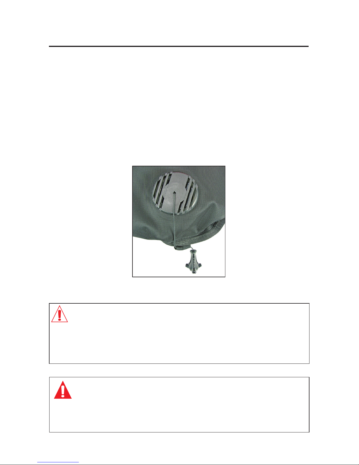
Your BC comes equipped with a combination dump valve / over pressure relief
valve (OPRV). The primary function is to relieve excess air pressure inside the
bladder. If the internal pressure exceeds the spring pressure, the OPRV auto-
matically opens to release air, preventing damage to the BC. The dump valve
can also be opened manually by pulling on the pull knob and cord assembly to
quickly dump air from the BC. To close the dump valve, release the knob and
cord assembly.
To dump air as quickly as possible, always use the dump valve at the highest
point in the water column.
Page 29
BC Single
Cylinder Capacity
BC Buoyancy
BC Double
Cylinder Capacity
29
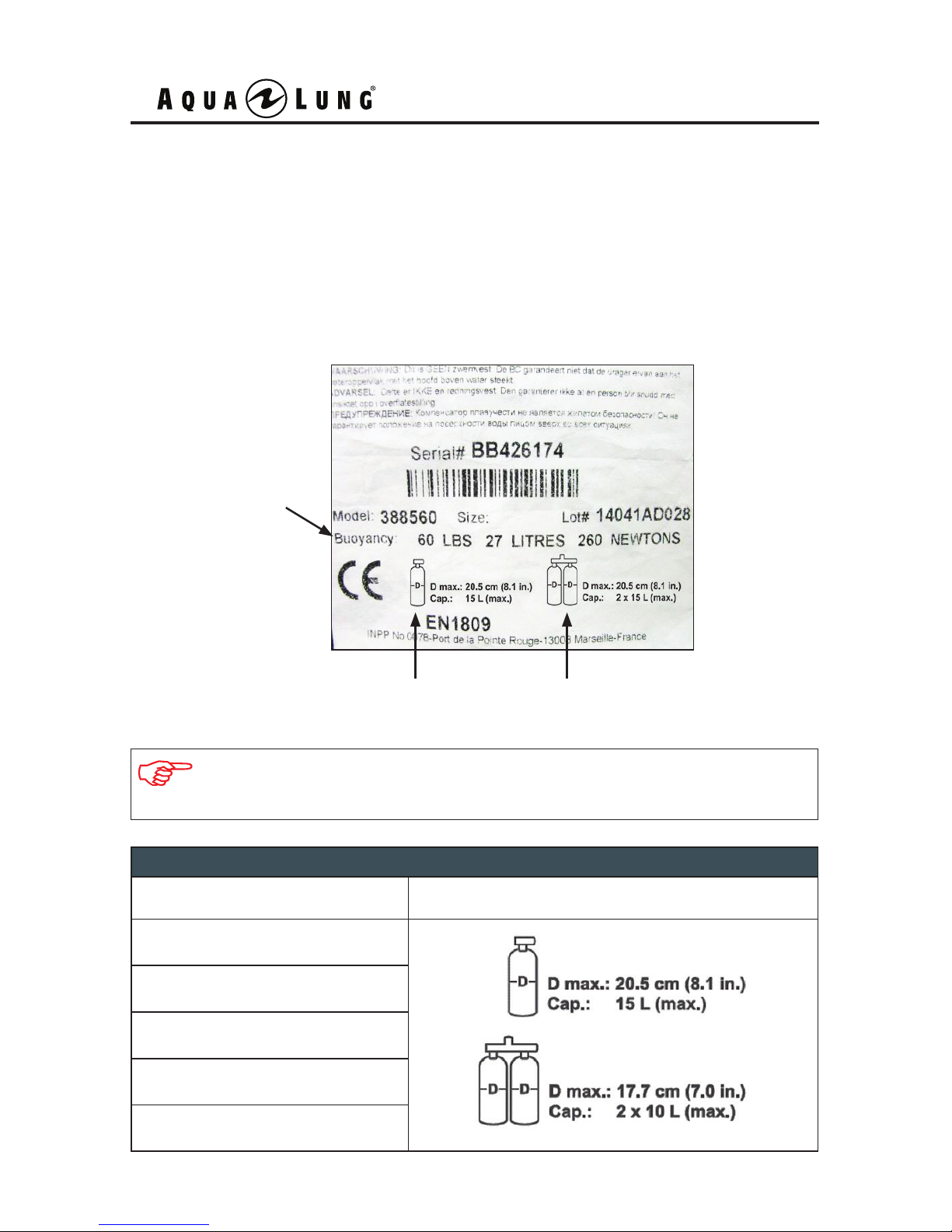
NOTE: The BC tag above is an example only. Reference the specic
tag located on your model BC.
BC 1 Cylinder Chart
BC 1 Size Cylinder Capacity
SM
MD
ML
LG
XL
BUOYANCY AND CYLINDER CAPABILITIES
A tag attached to each BC contains specic information regarding the
characteristics of your particular model BC, such as buoyancy and cylinder
capabilities. It is important to review this information in order to know the proper
cylinder sizes that may be used and to ensure the amount of weight being used
does not exceed the buoyancy of the BC.
Page 30
BC 1 User's Manual
30
Before adapting your BC for use with double cylinders, it is important to compare
the buoyancy of your particular BC size and model with the specications of
the cylinders, the amount of weight you will carry, and the type of exposure suit
you will wear.
Your BC’s backpack or harness may also have certain weight limitations
depending on the size and model, as double cylinders vary in both size
and weight. To ensure your safety, refer to the Buoyancy and Cylinder
Capabilities section of this manual prior to attaching double cylinders to
conrm the approved double cylinders for your particular BC.
Your BC can accommodate a twin tank kit. Identify which cylinder band your
BC uses and choose from the following options:
• 427107 GripLock Twin Cylinder Kit.
• 427042 Universal Twin Cylinder Kit.
Double Cylinder Set-up
WARNING: When fully charged and worn together as doubles, some
cylinders may create enough negative buoyancy to counteract the
amount of buoyancy your BC can provide. At depth, this can lead to a
dangerous situation if your wetsuit becomes compressed and you can
no longer achieve positive buoyancy by jettisoning weight. The excess
weight of some double cylinders may also lead to structural failure of
the backpack or harness. Such an event while diving may separate you
from your primary air source, and could lead to serious injury or death.
Page 31
31
PRE-DIVE INSPECTION
Before each use, the BC must be given a thorough visual inspection and functional
test. NEVER dive with a BC that shows signs of damage to its bladder, valves or
any components until it has received a complete inspection and service from an
Authorized Aqua Lung Dealer or Distributor.
5. Make a nal check of the cylinder band tension to ensure it has been secured
properly. Re-tighten if necessary.
6. Before entering the water, check both weight pouches (if equipped) to ensure
that they are correctly fastened to the BC.
WARNING: Loss of the releasable weight pouches can occur if
they are not properly secured. Involuntary release of both weight
pouches can cause a sudden increase in buoyancy causing a rapid
ascent, and could lead to serious injury or death due to arterial gas
embolism, decompression sickness, or drowning.
1. Visually inspect the entire BC for cuts, punctures, frayed seams, excessive
abrasion, damaged or missing hardware and other damage of any kind.
2. Connect the inator to a source of clean air, via the MP quick disconnect
hose. Inate the BC intermittently to ensure that the airow is unobstructed
and that the airow stops completely when the inator button is released
(See Ination Methods).
3. Manually operate the dump valve by pulling on the pull knob and cord assembly
to release air from inside the BC, then fully inate the BC until the (OPRV) opens
(See Deation Methods). Examine the operation of the (OPRV) / dump valve by
repeatedly inating the BC to ensure the valve opens to relieve excess pressure,
yet closes immediately afterwards to allow the bladder to remain taut and fully
inated.
4. Push the oral inator button to ensure a rapid and unobstructed exhaust
from the valve (See Deation Methods). Fully inate the BC once again and
disconnect the MP hose from the power inator. Let the BC stand for 10
minutes and listen for any leaks.
WARNING: If you can hear any leaks, or if the bladder begins to
deate within 10 minutes, DO NOT attempt to use the BC until it
has received a complete inspection and service.
Page 32
BC 1 User's Manual
32
1. Avoid prolonged exposure to direct sunlight and extreme heat. Nylon fabric
can quickly fade when exposed to the sun’s ultraviolet rays, and extreme
heat may damage the welded bladder seams.
2. Avoid repeated or prolonged use in heavily chlorinated water, which can
cause the BC fabric to discolor and decay prematurely.
3. Do not allow the BC to chafe against any sharp objects or rough surfaces
that could abrade or puncture the bladder. Do not set or drop heavy objects
such as block weights on the BC.
4. Avoid any contact with oil, gasoline, aerosols, or chemical solvents.
5. To preserve the life of the bladder, rinse it inside and out with fresh water after
every day of use, using the following procedure:
a) Pressurize the power inator with medium pressure (MP) air via the MP hose.
b) Using a garden hose, direct water through the oral inator mouthpiece
to ush the interior of the bladder, and then thoroughly rinse the exterior
of the BC.
c) Completely drain the bladder of water, either through the oral inator or
through the over-pressure relief valve.
d) After rinsing, inate the BC, and allow it to dry inside and out.
POST-DIVE CARE & MAINTENANCE
CAUTION: Before rinsing, ensure that the inator is pressurized
with air. This will prevent debris and contaminants from entering
the valve mechanism if the inator button is accidentally depressed.
6. Thoroughly rinse each part of the weight release mechanism on the BC and
weight pocket (if equipped). Visually inspect both parts of the mechanism to
make sure they are free of any debris (sand, salt, silt, rocks, etc.) that could
hinder the smooth operation of the mechanism. Connect and release the
mechanism several times to ensure proper operation.
Storage
Store the BC partially inated, away from direct sunlight and in a clean, dry
area. Do not store the BC in an enclosed space, such as a car trunk, where
temperatures may fall below 0ºF (-18ºC) or rise above 120ºF (49ºC).
Page 33
33
NOTE: It is important to obtain prescribed dealer service for your BC
annually, from an Authorized Aqua Lung Dealer or Distributor. Your
personal safety and the mechanical integrity of your BC depends on it.
WARNING: DO NOT attempt to perform any disassembly or service
of your BC. Service requiring disassembly must only be performed
by a factory-trained Aqua Lung technician. To obtain service or
repair, see an Authorized Aqua Lung Dealer or Distributor.
1. It cannot be assumed that the BC is in good working order on the basis that it
has received little use since it was last serviced. Remember that prolonged
or improper storage can still result in internal corrosion and/or deterioration
of o-ring seals and valve springs, as well as bladder seam degradation.
2. It is imperative that you obtain prescribed dealer service for your BC at least
once a year from an authorized dealer, including a general air leak inspection
and complete overhaul of the power inator and Over Pressure Relief Valve
(OPRV). Your BC may require this service more frequently, depending on the
amount of use it receives and the environmental conditions it is used in.
3. If the BC is used for rental or training purposes in salt, chlorinated, or silted fresh
water, it will require prescribed dealer service every three to six months. Use in
chlorinated water will greatly accelerate the deterioration of most components,
and require more frequent service.
4. DO NOT attempt to perform any disassembly or overhaul service of your
BC. Doing so may cause the BC to dangerously malfunction, and will render
the warranty null and void. All service must be performed by an Authorized
Aqua Lung Dealer or Distributor.
DEALER INSPECTION AND SERVICE
Page 34
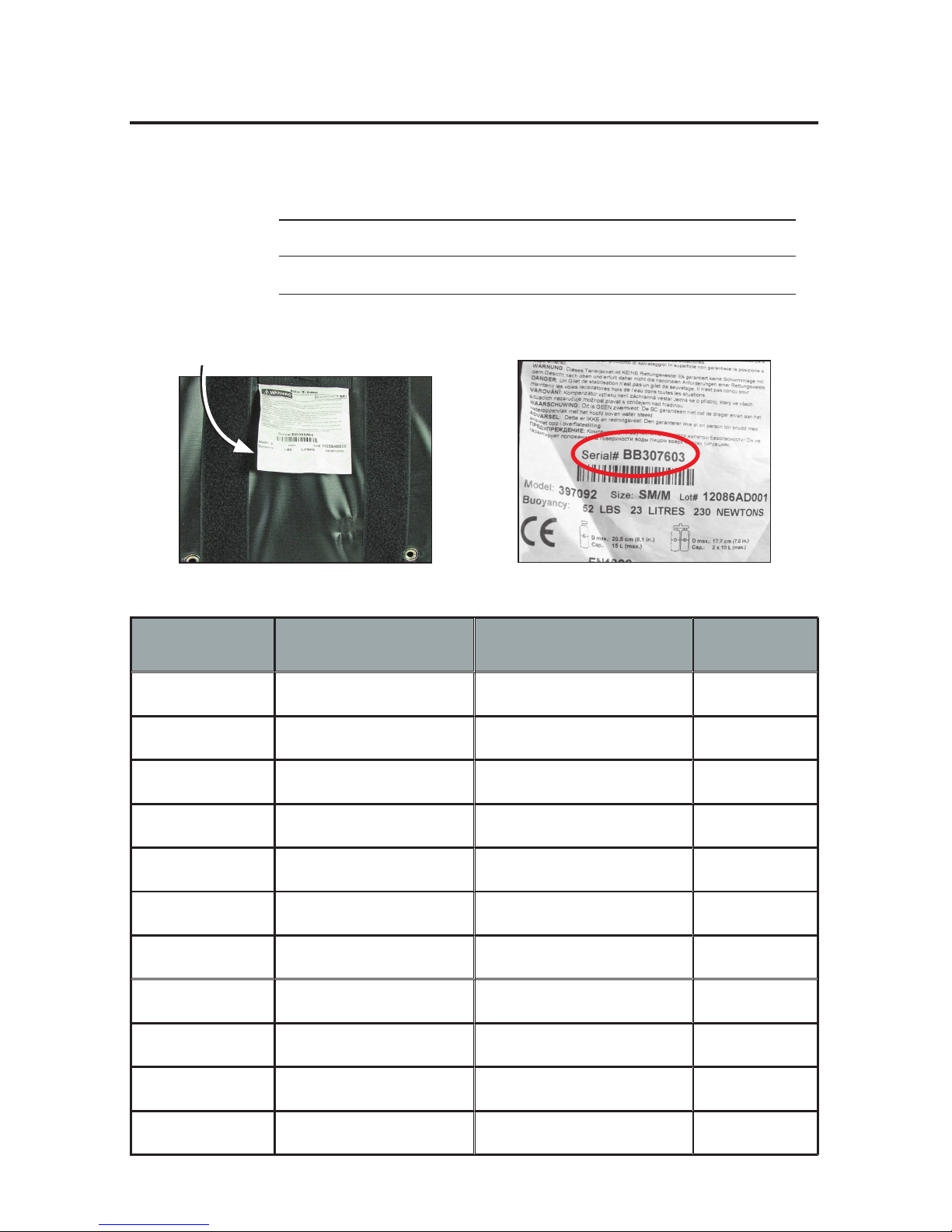
Serial #
Serial # is located BC Tag
BC 1 User's Manual
34
Purchase Date:
BC Model:
Serial Number:
Annual Service and Inspection Record
DATE TECHNICIAN
NAME & NUMBER
TECHNICIAN
SIGNATURE
STAMP
Page 35

35
For detailed information on product warranties, please refer to the Terms and
Conditions Section of the Aqua Lu n g M ilitar y and P r ofes sional Buyers Guide.
The buyers guide can be viewed or downloaded from the Aqua Lung Military
and Professional website at www.aqualung.com/militaryandprofessional
WARRANTY INFORMATION
Page 36
©2016 Aqua Lung International
2340 Cousteau Court • Vista, CA 92081
Phone (760) 597-5000 • Fax (760) 597-4900
www.aqualung.com/militaryandprofessional
BC 1
Buoyancy Compensator
User's Manual
 Loading...