

Quick start guide
computeraqu
a
Quick start guide
Quick start guideQuick start guide
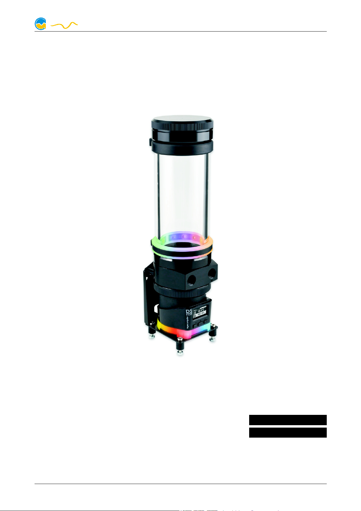
ULTITUBE D5
ULTITUBE D5
ENGLISH: PAGE 1
DEUTSCH: SEITE 9
Current as of April 2020
All information contained in this manual is subject to change without prior notice.
All rights reserved.
© 2020 Aqua Computer GmbH & Co. KG - 1 -
Gelliehäuser Str. 1, 37130 Gleichen

ULTITUBE D5
computeraqu
a
Table of contents
Table of contents
Table of contentsTable of contents
1. Safety precautions.........................................................................2
2. Scope of delivery..........................................................................3
3. Assembly instructions.....................................................................3
3.1. Installation of a D5 pump motor.....................................................3
3.2. Installation into a PC case..............................................................3
3.3. RGBpx LED ring............................................................................4
3.4. Disassembly and reassembly of the reservoir lid for filling..................4
3.5. Integration into the cooling loop.....................................................4
4. D5 NEXT......................................................................................4
4.1. Detachable control unit, mounting options......................................4
4.2. Electrical connections....................................................................5
4.3. Power Connector..........................................................................5
4.4. Connector “USB”..........................................................................5
4.5. Connector “Fan” for fan or flow sensor...........................................5
4.6. Connector “Bus” for aquabus or RGBpx..........................................6
4.7. Technical details D5 NEXT.............................................................6
4.8. Restore factory defaults..................................................................7
4.9. Full manual and aquasuite software................................................7
5. D5 PWM......................................................................................7
5.1. Electrical connections....................................................................7
5.2. Technical details D5 PWM.............................................................7
6. Technical details and care instructions............................................7
6.1. Technical details...........................................................................7
6.2. Care instructions...........................................................................8
6.3. Waste disposal.............................................................................8
6.4. Contact Aqua Computer...............................................................8
1.
1. Safety precautions
Safety precautions
1.1.
Safety precautionsSafety precautions
The following safety precautions have to be observed at all times:
● Read this manual thoroughly and entirely!
● Save your data onto suitable media before working on your hardware!
● This product is not designed for use in life support appliances, devices, or
systems where malfunction of this product can reasonably be expected to result in personal injury. Aqua Computer GmbH & Co. KG customers using or
selling this product for use in such application do so at their own risk and
agree to fully indemnify Aqua Computer GmbH & Co. KG for any damages
resulting from such application!
- 2 - Aqua Computer GmbH & Co. KG © 2020
Gelliehäuser Str. 1, 37130 Gleichen

ULTITUBE D5
computeraqu
a
2.
2. Scope of delivery
Scope of delivery
2.2.
Scope of deliveryScope of delivery
● One reservoir
● Mounting material
● This manual
3.
3. Assembly instructions
Assembly instructions
3.3.
Assembly instructionsAssembly instructions
3.1.
3.1. Installation of a D5 pump motor
3.1.3.1.
Skip this section if a pump is already installed into the reservoir.
If you have a complete D5 pump instead of a D5 pump motor, you will have to
disassemble the pump first. The only parts needed are the housing with electronic
components and the impeller.
Install the pump motor as follows:
Installation of a D5 pump motor
Installation of a D5 pump motorInstallation of a D5 pump motor
1. Place the gasket into the ULTITUBE base part.
2. Place the ULTITUBE base part on top of the D5 pump motor.
3. D5 NEXT only: Remove the controller unit from the pump
4. Slide the mounting ring onto the rear side of the pump motor and fasten the
ring by screwing it onto the ULTITUBE base part.
5. D5 NEXT only: Re-attach the controller unit to the pump.
3.2.
3.2. Installation into a PC case
3.2.3.2.
Mounting material for upright standing installation (for example to the bottom of
the case) or lateral installation (for example to a side panel of the case) is included
in delivery. A standing installation should be preferred for stability reasons.
If the reservoir is used in combination with a D5 NEXT pump, the reservoir can be
installed standing directly on the pump. Additional stabilization is recommended, a
suitable mounting bracket is available (product code 34111, included in reservoir
variants 34100, 34109 and 34110 only).
For additional, vibration dampening fixation in the upper area of the glass tube, a
rubber fixation ring is available. The rubber ring can be slipped over the top of the
reservoir onto the glass tube (product code 34114, included in ULTITUBE D5 PRO
only).
Furthermore, mounting brackets for installation to standard 120 mm or 140 mm
fan mounting positions are available as accessories (product codes 34112 and
34113, not included in delivery.
Installation into a PC case
Installation into a PC caseInstallation into a PC case
© 2020 Aqua Computer GmbH & Co. KG - 3 -
Gelliehäuser Str. 1, 37130 Gleichen

ULTITUBE D5
computeraqu
a
3.3.
3.3. RGBpx LED ring
3.3.3.3.
For effective illumination of the reservoir, a RGBpx LED ring is available (product
code 34115, included in ULTITUBE D5 PRO only).
The LED ring consists of a transparent silicone ring and a black rubber LED holder.
For installation, slide the silicone ring over the top of the reservoir to your preferred position on the glass tube. Insert the rubber LED holder into the silicone
ring.
Connect the LED ring (connector marked with the word “IN”) to a compatible
RGBpx output of an Aqua Computer device. A suitable cable is included in delivery. If required, additional RGBpx components can be connected (daisy chained)
to the adjacent connector (connector marked with the word “OUT”).
3.4.
3.4. Disassembly and reassembly of the reservoir lid for filling
3.4.3.4.
To remove the lid, hold the glass tube and turn the lid counter-clockwise. Take
care not to lose the gasket. For reassembly, place the gasket onto the glass tube
and screw the lid onto the reservoir. Do not use any tools and use only moderate
force.
RGBpx LED ring
RGBpx LED ringRGBpx LED ring
Disassembly and reassembly of the reservoir lid for filling
Disassembly and reassembly of the reservoir lid for fillingDisassembly and reassembly of the reservoir lid for filling
3.5.
3.5. Integration into the cooling loop
3.5.3.5.
Connect the return line to the reservoir connector engraved with the word “IN”
and connect the other line to the remaining connector. Use light force only when
screwing in fittings in order not to damage the threads in the plastic base part!
4.
4. D5 NEXT
4.4.
This chapter applies to variants with D5 NEXT pump only (product numbers 34100,
34109, 34110).
4.1.
4.1. Detachable control unit, mounting options
4.1.4.1.
The controller unit of the pump can be removed by pulling it off the pump motor
unit in a straight line. Make sure that no power is supplied to the pump whenever
the controller unit is being removed from or re-attached to the pump motor unit!
The controller unit can only be attached to the pump motor unit in a given orientation. Do not use excessive force but re-check the orientation if you encounter
problems re-attaching the controller unit.
The orientation of the display can only be adjusted by rotating the entire pump. In
order to rotate the pump, the mounting ring attaching the pump to the reservoir
needs to be unscrewed, which can result in coolant leakage! Completely drain the
coolant before loosening the mounting ring and remove the controller unit from
the pump! After rotating the pump, re-fasten the mounting ring by hand.
Integration into the cooling loop
Integration into the cooling loopIntegration into the cooling loop
D5 NEXT
D5 NEXTD5 NEXT
Detachable control unit, mounting options
Detachable control unit, mounting optionsDetachable control unit, mounting options
- 4 - Aqua Computer GmbH & Co. KG © 2020
Gelliehäuser Str. 1, 37130 Gleichen

ULTITUBE D5
computeraqu
a
In case the reservoir is installed without using the mounting plate of the pump, the
mounting plate and silicone damper of the pump can be replaced with a flat silicone insert.
Please note that all mounting options that make use of the silicone damper require
the pump to be installed vertically above the damper and additionally the reservoir
to be firmly secured to the PC case! The silicone damper of the pump is not designed to withstand lateral stress or transportation of the PC!
4.2.
4.2. Electrical connections
4.2.4.2.
ATTENTION: Completely turn off your power supply or disconnect the mains power cord from the wall outlet before connecting or disconnecting any cables to/from
the device!
4.3.
4.3. Power Connector
4.3.4.3.
Connect a SATA power plug of your PC's power supply unit to this connector. Do
not use excessive force but double check the polarity of the plug if you are having
trouble to connect.
Pin assignment: Pin 1, 2, 3, 11: not connected
Electrical connections
Electrical connectionsElectrical connections
Power Connector
Power ConnectorPower Connector
Pin 4, 5, 6, 10, 12: GND
Pin 7, 8, 9: 5 V DC
Pin 13, 14, 15: 12 V DC
4.4.
4.4. Connector “USB”
4.4.4.4.
This connector is used for USB communication with a PC. Connect to an internal
USB header of your motherboard. Take special care to make sure the pin alignment matches your motherboard! The USB interface is used for data exchange
with the PC and not required for pump operation.
Pin assignment: Pin 1: GND (black, optional)
4.5.
4.5. Connector “Fan” for fan or flow sensor
4.5.4.5.
Depending on configuration, this connector can either be used as a PWM regulated fan output with speed signal processing or to connect a flow sensor. Simultaneous use of both functions is not possible!
Pin assignment: Pin 1: GND
Connector “USB”
Connector “USB”Connector “USB”
Pin 2: GND (black)
Pin 3: D+ (green)
Pin 4: D- (white)
Pin 5: +5 V (red)
Connector “Fan” for fan or flow sensor
Connector “Fan” for fan or flow sensorConnector “Fan” for fan or flow sensor
Pin 2: 12 V / max. 25 W
Pin 3: Speed signal
Pin 4: PWM signal
© 2020 Aqua Computer GmbH & Co. KG - 5 -
Gelliehäuser Str. 1, 37130 Gleichen

ULTITUBE D5
computeraqu
a
Flow sensor and special interconnecting cable are optional accessories and not included in delivery.
Compatible flow sensors:
● Flow sensor with 5.6 mm nozzle (53061)
● Flow sensor “high flow” (53068)
● Connection cable for flow sensor (53027, 53100)
4.6.
4.6. Connector “Bus” for aquabus or RGBpx
4.6.4.6.
Depending on configuration, this connector can either be used for communication
with other Aqua Computer devices or to connect RGBpx products (up to 90 addressable LEDs). Simultaneous use of both functions is not possible!
Compatible aquabus devices:
Connector “Bus” for aquabus or RGBpx
Connector “Bus” for aquabus or RGBpxConnector “Bus” for aquabus or RGBpx
● aquaero 6 XT (53146, 53206, 53250, 53251, 53262, 53263)
● aquaero 6 PRO (53145, 53253)
● aquaero 6 LT (53234)
● aquaero 5 XT (53089, 53125, 53249)
● aquaero 5 PRO (53090, 53252)
● aquaero 5 LT (53095)
If the RGBpx product to be connected has more than one RGBpx connector, the
connector marked with the word “IN” must be used! Additional RGBpx products
may be connected to the “OUT” connector.
Compatible RGBpx products:
● RGBpx LED-Strip (53268, 53269, 53270)
● RGBpx lighting set for PC cases (53271)
● RGBpx lighting set for monitors (53272)
● RGBpx Splitty4 (53267)
● RGBpx LED ring of ULTITUBE series reservoirs (34094, 34095, 34096,
34100, 34109, 34110)
● RGBpx LED ring for ULTITUBE (34115)
● RGBpx LED ring for aqualis 450/880 (53274)
● RGBpx LED ring for aqualis 100/150 (53276)
● RGBpx LED ring for 60 mm reservoir (53277)
● RGBpx cable (53259, 53260, 53261, 53266)
4.7.
4.7. Technical details D5 NEXT
4.7.4.7.
Technical details D5 NEXT
Technical details D5 NEXTTechnical details D5 NEXT
Power supply voltage (Vin): 5 V DC ±5 %, 12 V DC ±5 %
Maximum power consumption: 65 Watts (including fan and RGBpx)
Maximum pump pressure: 370 mbar (approx. 3.7 m water head)
Maximum fan output power: 25 Watts
Ambient temperature range: 10 to 40 °C (noncondensing)
Coolant temperature: 0 to 50 °C
The pump must not run dry for longer periods of time!
- 6 - Aqua Computer GmbH & Co. KG © 2020
Gelliehäuser Str. 1, 37130 Gleichen

ULTITUBE D5
computeraqu
a
4.8.
4.8. Restore factory defaults
4.8.4.8.
There are two options to reset the pump controller to factory defaults. Restoring
factory defaults may be useful if the pump is not properly operating or if erroneous
settings have been saved into the pump.
4.9.
4.9. Full manual and aquasuite software
4.9.4.9.
For configuration and monitoring of D5 NEXT pumps, the aquasuite software is
available for download from our website www.aqua-computer.de. You will find the
most up-to-date version as well as the complete operation manual for the D5
NEXT pump in the support section of the website.
Restore factory defaults
Restore factory defaultsRestore factory defaults
1. aquasuite: Click the “Reset device to factory defaults” button on the “System” screen.
2. Device menu: Select “System”, then “Factory defaults” and confirm by pressing the middle key.
Full manual and aquasuite software
Full manual and aquasuite softwareFull manual and aquasuite software
5.
5. D5 PWM
D5 PWM
5.5.
D5 PWMD5 PWM
This chapter applies to variants with D5 PWM pump only (product numbers 34097,
34098, 34099).
5.1.
5.1. Electrical connections
5.1.5.1.
Connect the power supply connector of the pump to a matching connector of the
power supply unit of the computer.
The pump speed can be adjusted using a compatible PWM fan connector. For
monitoring purposes, the pump generates a speed signal. However, a valid speed
signal cannot guarantee an actual flow of coolant!
5.2.
5.2. Technical details D5 PWM
5.2.5.2.
Power supply voltage (Vin): 8 – 24 V DC
Current consumption: 0.25 – 1.9 A
Ambient temperature range: 10 to 40 °C (noncondensing)
Coolant temperature: 0 to 50 °C
The pump must not run dry for longer periods of time!
Electrical connections
Electrical connectionsElectrical connections
Technical details D5 PWM
Technical details D5 PWMTechnical details D5 PWM
6.
6. Technical details and care instructions
Technical details and care instructions
6.6.
Technical details and care instructionsTechnical details and care instructions
6.1.
6.1. Technical details
6.1.6.1.
Capacity: ca. 230/350/470 ml (ULTITUBE 100/150/200)
Thread size: G ¼
Ambient temperature range: 10 to 40 °C (noncondensing)
Compatible coolants: Double Protect Ultra, water
© 2020 Aqua Computer GmbH & Co. KG - 7 -
Technical details
Technical detailsTechnical details
Gelliehäuser Str. 1, 37130 Gleichen

ULTITUBE D5
computeraqu
a
Coolant temperature: 0 to 50 °C
Footprint (L x W): ca. 72 x 72 mm (without cables/mounting material)
Height with D5 pump: ca. 200/250/300 mm (ULTITUBE 100/150/200)
Height with D5 NEXT pump: ca. 215/265/315 mm (ULTITUBE 100/150/200)
6.2.
6.2. Care instructions
6.2.6.2.
Use a dry and soft cloth for cleaning. All electronic components and headers must
not get in contact with coolant or water!
6.3.
6.3. Waste disposal
6.3.6.3.
This device has to be disposed of as electronic waste. Please check
your local regulations for disposal of electronic waste.
6.4.
6.4. Contact Aqua Computer
6.4.6.4.
We are always happy to answer questions regarding our products and to receive
feedback. For answers on frequently asked questions, please also check our website www.aqua-computer.de. You might also want to visit our forums and discuss
our products with experienced moderators and thousands of members – available
24/7. To get in direct contact with our customer support team, we offer several
options:
Care instructions
Care instructionsCare instructions
Waste disposal
Waste disposalWaste disposal
Contact Aqua Computer
Contact Aqua ComputerContact Aqua Computer
Email: support@aqua-computer.de
Postal address: Aqua Computer GmbH & Co. KG
Gelliehäuser Str. 1
37130 Gleichen
Germany
Tel: +49 (0) 5508 9749290 (9-16 h CET, German and English language)
- 8 - Aqua Computer GmbH & Co. KG © 2020
Gelliehäuser Str. 1, 37130 Gleichen
 Loading...