

Aqua Computer Hubby7 Service Manual
Installation and user manual Hubby 7, 06/2016
c
o
m
p
u
t
e
r
a
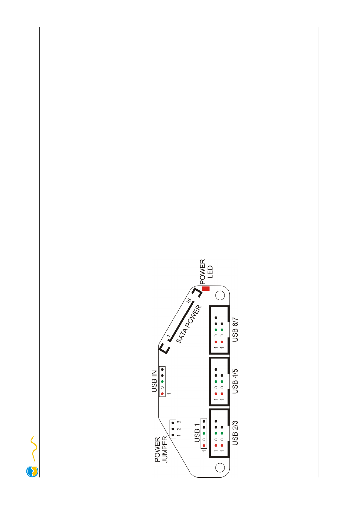
Pin 7-9 +5 V DC
Pin 1-3, 11, 13-15 not connected
Pin 2 D- (white)
Pin 3 D+ (green)
Pin 4 GND (black)
Pin 5 not connected or GND (black)
Jumper position 1-2 closed:
Jumper position 1-2 closed:Jumper position 1-2 closed:
Jumper position 1-2 closed: Power supplied via USB IN. Maximum cur-
rent for all ports 500 mA combined. Depending on motherboard config-
uration, the hub will also be powered during standby and connected de-
Jumper position 2-3 closed:
vices may be used to wake the PC up from standby.
Jumper position 2-3 closed:Jumper position 2-3 closed:
Jumper position 2-3 closed: Power supplied via SATA power connector.
Maximum current for all ports 1000 mA combined, split up as 500 mA
for ports 1, 2 and 3 combined and 500 mA for ports 4, 5, 6 and 7
combined. Connect SATA POWER to an available connector of your
Driver installation:
PSU. No power is supplied during standby.
Driver installation:Driver installation:
Driver installation: All current operating systems will automatically detect
the hub and use generic drivers. No special drivers are required.
Pin assignment USB:
Pin assignment USB:Pin assignment USB:
Pin assignment USB: Pin 1 +5 V (red)
Pin assignment SATA POWER:
Pin assignment SATA POWER:Pin assignment SATA POWER:
Pin assignment SATA POWER: Pin 4-6, 10, 12 GND
Installation instructions
Internal USB 2.0 hub with 7 ports for use inside a personal computer.
Mounting above motherboard:
Installation instructionsInstallation instructions
Installation instructions
Mounting above motherboard: Mounting above motherboard:
Mounting above motherboard: Remove two of the motherboard retain-
ing screws from suitable positions. Place two plastic spacers on top of
each opening and place the hub on top of the spacers. Secure hub, spa-
ces and motherboard with screws supplied with the hub. Depending on
your PC case, either metric or imperial screws are required. Both types
Mounting with hook-and-loop strip:
are supplied with the hub.
Mounting with hook-and-loop strip:Mounting with hook-and-loop strip:
Mounting with hook-and-loop strip: Remove the protective film from one
side of the hook-and-loop strip and attach the strip to the bottom side of
the hub. Remove the second protective film and attach the hub to a suit-
able surface inside the PC case.
USB connection to PC:
USB connection to PC:USB connection to PC:
USB connection to PC: Connect the USB IN header of the hub with an
internal USB header of the motherboard. Take special care to make sure
Power supply:
the pin alignment is correct!
Power supply:Power supply:
Power supply: The hub (including all connected devices) can either be
powered via USB connection or via SATA power supply connector. If
voltage is supplied to the hub, the POWER LED will light up red. If the
POWER LED does not light up although the PC is running, check the
POWER JUMPER position as well as all connected cables.
© 2016 Aqua Computer GmbH & Co. KG – Gelliehäuser Str. 1 – D-37130 Gleichen
 Loading...