

D5 NEXT
computeraqu
a
User and installation manual
User and installation manual
User and installation manualUser and installation manual
D5 NEXT
aquasuite version X.17
Current as of April 2020
All information contained in this manual is subject to change without prior notice.
All rights reserved.
© 2019-2020 Aqua Computer GmbH & Co. KG - 1 -
Gelliehäuser Str. 1, 37130 Gleichen
ENGLISH: PAGE 1
DEUTSCH: SEITE 31

D5 NEXT
computeraqu
a
Table of contents
Table of contents
Table of contentsTable of contents
1. Preface.........................................................................................4
2. Safety precautions.........................................................................4
3. Scope of delivery..........................................................................5
4. Assembly instructions.....................................................................5
4.1. Detachable control unit, mounting options......................................5
4.2. Installation to a top/cover or reservoir.............................................6
4.3. Permitted pump orientations...........................................................6
5. Electrical connections....................................................................6
5.1. Power Connector..........................................................................6
5.2. Connector “USB”..........................................................................6
5.3. Connector “Fan” for fan or flow sensor...........................................7
5.4. Connector “Bus” for aquabus or RGBpx..........................................7
6. Operation....................................................................................8
6.1. Operation via keys and display.......................................................8
6.2. Configuration using USB connection...............................................8
7. aquasuite software........................................................................8
7.1. Installation of the aquasuite software...............................................8
7.2. Basic operation............................................................................9
7.3. Symbols in the headlines................................................................9
8. Overview pages (aquasuite)...........................................................9
8.1. Desktop mode............................................................................10
8.2. Creating new overview pages and activating edit mode..................10
8.3. Adding new elements..................................................................10
8.4. Editing existing elements..............................................................10
8.5. Values and names......................................................................10
8.6. Detailed data elements................................................................11
8.7. Log data chart............................................................................11
8.8. User defined: Images, text, drawing elements.................................11
8.9. Export and import of overview pages.............................................12
9. Data quick view and data log (aquasuite).....................................12
9.1. Log settings................................................................................12
9.2. Analyze data..............................................................................13
9.3. Manual data export.....................................................................14
9.4. Automatic data export.................................................................14
10. Pump configuration...................................................................14
10.1. Pump mode power preset..........................................................14
10.2. Pump mode temperature set point..............................................15
10.3. Pump mode curve controller......................................................15
10.4. Pump mode flow controller........................................................15
10.5. General pump settings..............................................................15
- 2 - Aqua Computer GmbH & Co. KG © 2019-2020
Gelliehäuser Str. 1, 37130 Gleichen

D5 NEXT
computeraqu
a
10.6. Pump behavior with aquabus connection to an aquaero...............16
11. Fan configuration.....................................................................16
11.1. Fan mode power preset.............................................................16
11.2. Fan mode temperature set point.................................................16
11.3. Fan mode curve controller.........................................................16
11.4. General fan settings..................................................................17
11.5. Fan behavior with aquabus connection to an aquaero..................17
11.6. Dual functionality – fan output or flow sensor input.......................17
12. RGBpx configuration.................................................................18
12.1. Basic RGBpx settings.................................................................18
12.2. LED mapping...........................................................................18
12.3. Sound controlled effects.............................................................18
12.4. AMBIENTpx effect.....................................................................18
13. Sensor configuration.................................................................19
13.1. Water temperature sensor..........................................................19
13.2. Options for flow rate measurement.............................................19
13.3. Virtual flow sensor.....................................................................19
13.4. Mechanical flow sensor.............................................................20
13.5. Software temperature sensors.....................................................20
14. Alarm configuration..................................................................21
14.1. Acoustic alarm and lighting........................................................21
14.2. Alarm reporting and alarm limits................................................21
14.3. System alarms..........................................................................22
15. Display configuration and information pages..............................22
15.1. Display settings.........................................................................22
15.2. Charts.....................................................................................23
15.3. Display pages...........................................................................23
16. Profiles.....................................................................................23
16.1. Manual profile selection............................................................23
16.2. Automatic profile selection.........................................................23
16.3. Profile configuration..................................................................23
17. System settings D5 NEXT...........................................................23
17.1. Device information....................................................................23
17.2. Factory defaults........................................................................24
17.3. aquabus/RGBpx configuration...................................................24
17.4. Firmware update and language selection (aquasuite only).............24
18. Playground (aquasuite)..............................................................24
18.1. Virtual Software Sensors.............................................................24
18.2. Global profiles.........................................................................25
18.3. Hotkeys...................................................................................25
19. aquasuite web..........................................................................26
19.1. Data export..............................................................................26
© 2019-2020 Aqua Computer GmbH & Co. KG - 3 -
Gelliehäuser Str. 1, 37130 Gleichen

D5 NEXT
computeraqu
a
19.2. Data access.............................................................................26
19.3. Data import..............................................................................27
20. Basic settings (aquasuite)...........................................................27
20.1. Language................................................................................27
20.2. Reorder menu items..................................................................27
20.3. Units.......................................................................................27
20.4. Application start-up...................................................................27
20.5. Service administration...............................................................28
20.6. Audio and video.......................................................................28
20.7. Updates and update service.......................................................28
21. Technical details and care instructions........................................29
21.1. Technical details.......................................................................29
21.2. Restore factory defaults..............................................................29
21.3. Care instructions.......................................................................29
21.4. Waste disposal.........................................................................30
21.5. Contact Aqua Computer............................................................30
1.
1. Preface
Preface
1.1.
PrefacePreface
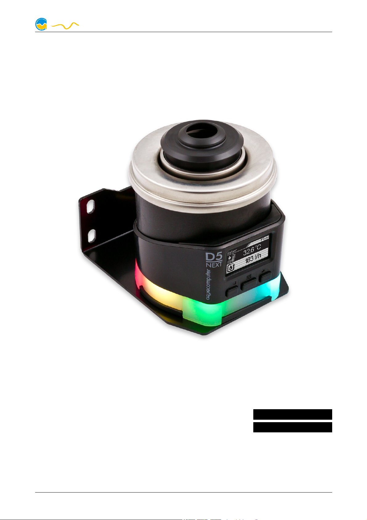
The D5 NEXT pump is built for longevity and to match the highest quality standards. It has been particularly designed for PC water cooling systems. The pump is
based on the Laing/Lowara/Xylem D5vario pump and the stainless steel top with
ceramic ball, the pump rotor and part of the electronics and housing are manufactured by Laing/Lowara/Xylem.
Laing D5 pumps are based on a shaftless spherical motor: The hemispherical rotor/impeller unit sits on an ultra-hard, wear-resistant ceramic ball. Due to its self
adjusting properties, bearing play does not change even after prolonged use, the
pump keeps on running on a constantly low noise level.
In addition to the proven characteristics of the Laing D5 mechanics, the D5 NEXT
features outstanding monitoring and control options developed by Aqua Computer: The D5 NEXT is equipped with with an integrated fan controller for PWM fans,
an USB interface as well as either an aquabus interface or a RGBpx effect controller for up to 64 individually addressable LEDs. An OLED display can be used to
visualize current sensor readings or to configure the pump.
Considering the fast technical development, we reserve the right to perform alterations to the products at any time. It therefore is possible that your product does
not correspond precisely to the descriptions or especially the illustrations in this
manual.
2.
2. Safety precautions
Safety precautions
2.2.
Safety precautionsSafety precautions
The following safety precautions have to be observed at all times:
● Read this manual thoroughly and entirely!
- 4 - Aqua Computer GmbH & Co. KG © 2019-2020
Gelliehäuser Str. 1, 37130 Gleichen

D5 NEXT
computeraqu
a
● Save your data onto suitable media before working on your hardware!
● The pump must not be placed under water!
● The pump controller on the rear end of the pump must not get in contact
with water!
● The pump may only be used inside a PC case!
● The pump is not a suction pump. Make sure the pump chamber is filled with
water prior to operation!
● The pump is not suited for dry operation!
● This product is not designed for use in life support appliances, devices, or
systems where malfunction of this product can reasonably be expected to result in personal injury. Aqua Computer GmbH & Co. KG customers using or
selling this product for use in such application do so at their own risk and
agree to fully indemnify Aqua Computer GmbH & Co. KG for any damages
resulting from such application!
3.
3. Scope of delivery
Scope of delivery
3.3.
Scope of deliveryScope of delivery
The following scope of delivery applies to the retail version only, product code
41118:
● One D5 NEXT pump motor complete with detachable controller unit, sili-
cone damper (replacement part no. 94694) and mounting plate (replacement part no. 94766)
● One internal USB cable (replacement part no. 53215)
● One mounting bracket, black (replacement part no. 94719)
● One silicone insert (replacement part no. 94695)
● Three screws M3 x 12 mm, countersunk head (replacement part no. 91149)
● Three washers M3 (replacement part no. 91019)
● Three hexagon nuts M3 (replacement part no. 91017)
● Four screws M4 x 8 mm (replacement part no. 91007)
● Four hexagon nuts M4 (replacement part no. 91053)
● One manual
4.
4. Assembly instructions
Assembly instructions
4.4.
Assembly instructionsAssembly instructions
4.1.
4.1. Detachable control unit, mounting options
4.1.4.1.
Detachable control unit, mounting options
Detachable control unit, mounting optionsDetachable control unit, mounting options
The controller unit of the pump can be removed by pulling it off the pump motor
unit in a straight line. Make sure that no power is supplied to the pump whenever
the controller unit is being removed from or re-attached to the pump motor unit!
The controller unit can only be attached to the pump motor unit in a given orientation. Do not use excessive force but re-check the orientation if you encounter
problems re-attaching the controller unit.
The pump may be installed into the PC case using the supplied silicone damper
and mounting plate, either to a level surface or – using the supplied 90° bracket –
© 2019-2020 Aqua Computer GmbH & Co. KG - 5 -
Gelliehäuser Str. 1, 37130 Gleichen

D5 NEXT
computeraqu
a
to a vertical surface. If these mounting options are not used, the silicone damper
of the pump can be replaced with a flat silicone insert.
Please note that all mounting options that make use of the silicone damper require
the pump to be installed vertically above the damper and are not designed to
withstand lateral stress or transportation of the PC!
4.2.
4.2. Installation to a top/cover or reservoir
4.2.4.2.
For operation of the pump, a compatible top/cover is required, alternatively the
pump may be installed directly to a compatible reservoir. In both cases, the pump
motor will be held in place by fixation rings to be slid over the pump. In order to
do so, detach the controller unit from the pump motor unit, fasten the pump motor
using the fixation ring and re-attach the controller unit.
4.3.
4.3. Permitted pump orientations
4.3.4.3.
During operation, the impeller of the pump must be directed upwards or to the
side relative to the controller unit. Operation with downwards oriented, “hanging”
impeller is not permitted!
Installation to a top/cover or reservoir
Installation to a top/cover or reservoirInstallation to a top/cover or reservoir
Permitted pump orientations
Permitted pump orientationsPermitted pump orientations
5.
5. Electrical connections
Electrical connections
5.5.
Electrical connectionsElectrical connections
ATTENTION: Completely turn off your power supply or disconnect the mains power cord from the wall outlet before connecting or disconnecting any cables to/from
the device!
5.1.
5.1. Power Connector
5.1.5.1.
Connect a SATA power plug of your PC's power supply unit to this connector. Do
not use excessive force but double check the polarity of the plug if you are having
trouble to connect.
Pin assignment: Pin 1, 2, 3, 11: not connected
5.2.
5.2. Connector “USB”
5.2.5.2.
This connector is used for USB communication with a PC. Connect to an internal
USB header of your motherboard. Take special care to make sure the pin alignment matches your motherboard! The USB interface is used for data exchange
with the PC and not required for pump operation.
The corresponding connector on the motherboard is usually
a 9 pin connector with two independent USB ports. Both
rows of 4/5 pins can be used to connect an USB device.
Power Connector
Power ConnectorPower Connector
Pin 4, 5, 6, 10, 12: GND
Pin 7, 8, 9: 5 V DC
Pin 13, 14, 15: 12 V DC
Connector “USB”
Connector “USB”Connector “USB”
- 6 - Aqua Computer GmbH & Co. KG © 2019-2020
Gelliehäuser Str. 1, 37130 Gleichen

D5 NEXT
computeraqu
a
The black wires (GND) are to be connected to the side of the missing pin, see picture with colored pin assignment.
Pin assignment: Pin 1: GND (black, optional)
Pin 2: GND (black)
Pin 3: D+ (green)
Pin 4: D- (white)
Pin 5: +5 V (red)
5.3.
5.3. Connector “Fan” for fan or flow sensor
5.3.5.3.
Depending on configuration, this connector can either be used as a PWM regulated fan output with speed signal processing or to connect a flow sensor. Simultaneous use of both functions is not possible!
Pin assignment: Pin 1: GND
Flow sensor and special interconnecting cable are optional accessories and not included in delivery.
Compatible flow sensors:
Connector “Fan” for fan or flow sensor
Connector “Fan” for fan or flow sensorConnector “Fan” for fan or flow sensor
Pin 2: 12 V / max. 25 W
Pin 3: Speed signal
Pin 4: PWM signal
● Flow sensor with 5.6 mm nozzle (53061)
● Flow sensor “high flow” (53068)
● Connection cable for flow sensor (53027, 53100)
5.4.
5.4. Connector “Bus” for aquabus or RGBpx
5.4.5.4.
Connector “Bus” for aquabus or RGBpx
Connector “Bus” for aquabus or RGBpxConnector “Bus” for aquabus or RGBpx
Depending on configuration, this connector can either be used for communication
with other Aqua Computer devices or to connect RGBpx products (up to 90 addressable LEDs). Simultaneous use of both functions is not possible!
Compatible aquabus devices:
● aquaero 6 XT (53146, 53206, 53250, 53251, 53262, 53263)
● aquaero 6 PRO (53145, 53253)
● aquaero 6 LT (53234)
● aquaero 5 XT (53089, 53125, 53249)
● aquaero 5 PRO (53090, 53252)
● aquaero 5 LT (53095)
If the RGBpx product to be connected has more than one RGBpx connector, the
connector marked with the word “IN” must be used! Additional RGBpx products
may be connected to the “OUT” connector.
Compatible RGBpx products:
● RGBpx LED-Strip (53268, 53269, 53270)
● RGBpx lighting set (53271, 53272)
● RGBpx Splitty4 (53267)
● RGBpx LED ring for ULTITUBE (34115)
© 2019-2020 Aqua Computer GmbH & Co. KG - 7 -
Gelliehäuser Str. 1, 37130 Gleichen

D5 NEXT
computeraqu
a
● RGBpx LED ring for aqualis (53274, 53276)
● RGBpx LED ring for 60 mm reservoir (53277)
● RGBpx cable (53259, 53260, 53261, 53266)
6.
6. Operation
Operation
6.6.
OperationOperation
6.1.
6.1. Operation via keys and display
6.1.6.1.
The D5 NEXT is equipped with an OLED display and three keys and can be almost
completely configured using these.
The left and right key will select information pages during display mode and select
and alter menu entries. The middle key will open the device menu while in display
mode and confirm selected menu entries or values while in the menu.
During configuration via keys and display, the aquasuite software should be closed
on a connected PC! Otherwise, the aquasuite will overwrite and thereby cancel
any settings made on the device itself.
Operation via keys and display
Operation via keys and displayOperation via keys and display
6.2.
6.2. Configuration using USB connection
6.2.6.2.
The D5 NEXT can be connected to a PC via USB interface and can then be configured using the aquasuite software. Comprehensive visualization and logging options are also available in the aquasuite software. However, an USB connection is
not required for operation.
7.
7. aquasuite software
7.7.
The Windows software aquasuite is an extensive software suite and can be used
for configuration and monitoring. The software is not required for operation
though. All configuration parameters can be saved into the device's memory.
Please note: Depending on the type of product you are using, some features may
not be available for your device.
7.1.
7.1. Installation of the aquasuite software
7.1.7.1.
For configuration and monitoring of our products with USB interface, the aquasuite software is available for download from our website www.aqua-computer.de.
You will find the setup program in the support section of the website under Downloads/Software.
The setup program checks all connected USB devices for embedded update service periods and offers various aquasuite versions depending on detected devices.
If no device with update service for the latest aquasuite version is found, a warning
is displayed and older aquasuite versions that do not require an update service
purchase can be selected for installation. For installation and update service validation, an internet connection is required.
Configuration using USB connection
Configuration using USB connectionConfiguration using USB connection
aquasuite software
aquasuite softwareaquasuite software
Installation of the aquasuite software
Installation of the aquasuite softwareInstallation of the aquasuite software
- 8 - Aqua Computer GmbH & Co. KG © 2019-2020
Gelliehäuser Str. 1, 37130 Gleichen
D5 NEXT
computeraqu
a
The latest aquasuite version may also be installed if no suitable update service period has been found in a device. Subsequently, update service may be purchased
or an existing key may be entered within the aquasuite. These functions can be accessed in the aquasuite/Updates tab.
7.2.
7.2. Basic operation
7.2.7.2.
The program window is divided into two main areas. On the left side, a list of
“overview pages”, data quick view, data logger, device pages, aquasuite web and
aquasuite configuration is displayed, the right side shows the details of the currently selected list element. The list can be hidden or restored by clicking the arrow
symbol in the upper left corner.
List elements may be minimized or maximized for easier access by clicking the title
bar. The title bars may contain various symbols that will be explained in the following chapter.
7.3.
7.3. Symbols in the headlines
7.3.7.3.
Basic operation
Basic operationBasic operation
Symbols in the headlines
Symbols in the headlinesSymbols in the headlines
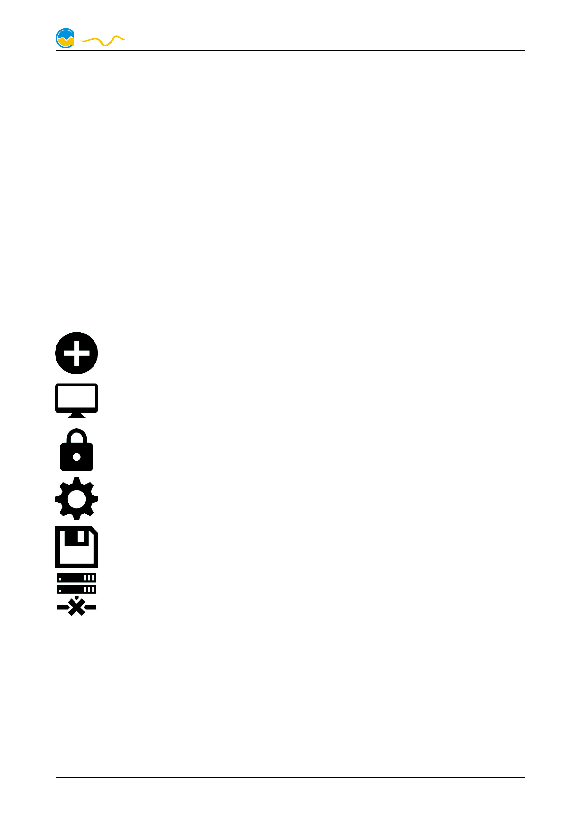
Click the plus symbol in the “Overview pages” headline to create a new
overview page.
Clicking the monitor symbol will toggle desktop mode for this overview
page. While desktop mode is active, the color of the symbol will change
to orange.
Overview page: Clicking the padlock symbol will unlock or lock this overview page for editing. Device: Device can not be used due to update service problems, see “Updates and update service” for details.
Clicking the gear symbol will access the basic configuration page of the
selected list element.
In order to save all settings into a device, click the disk symbol in the
headline.
This symbol indicates that communication with this device is not possible
at the moment. Check USB connection and power supply of the device if
necessary.
8.
8. Overview pages (aquasuite)
Overview pages (aquasuite)
8.8.
Overview pages (aquasuite)Overview pages (aquasuite)
Current sensor readings and diagrams from all supported devices can be displayed in overview pages. For each device a pre-configured overview page is automatically generated the first time the device is connected to the PC. These pages
can be individually modified and new pages can be created. Within one overview
page, data from all connected devices can be accessed.
© 2019-2020 Aqua Computer GmbH & Co. KG - 9 -
Gelliehäuser Str. 1, 37130 Gleichen
 Loading...