

Aqua Computer aquaero 5, aquaero 6 operation manual
AQUAERO 5/6
computeraqu
a
User and installation manual
User and installation manual
User and installation manualUser and installation manual
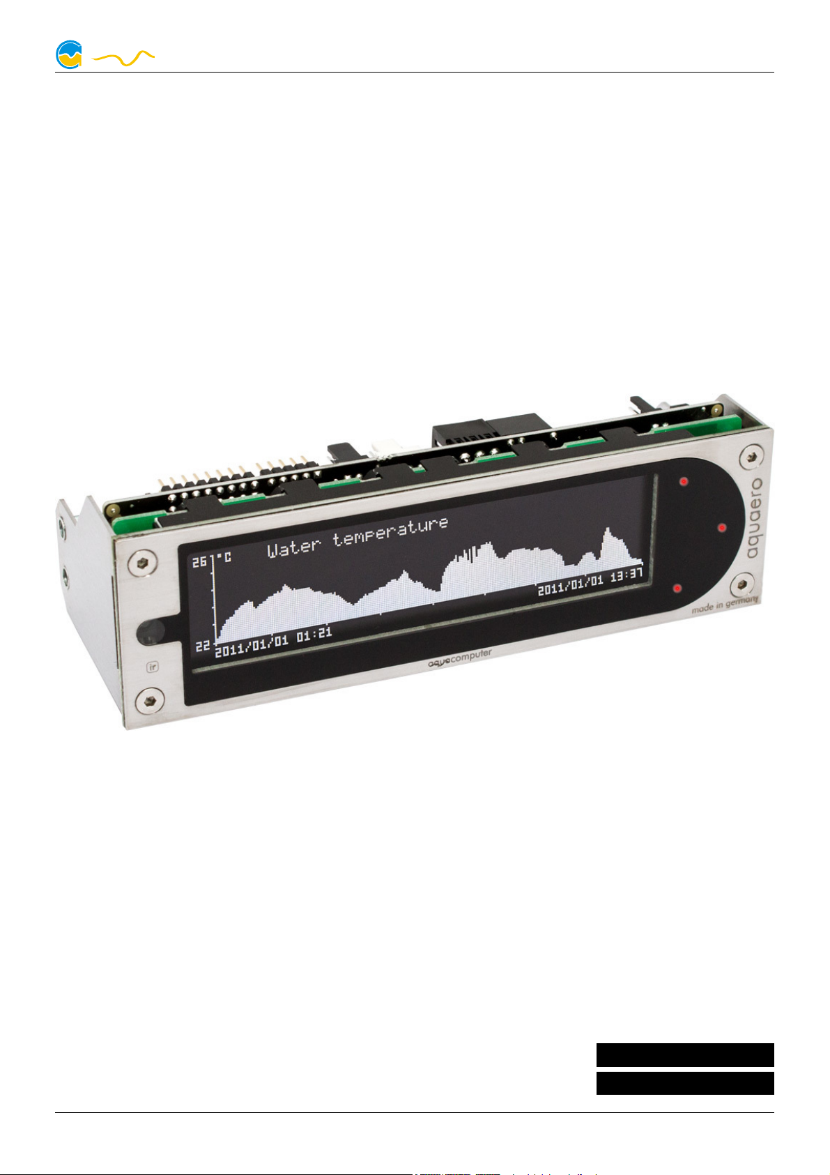
aquaero 5
aquaero 6
The information contained in this manual is subject to change without prior
notice. All rights reserved.
Current as of October 2016
© 2014-2016 Aqua Computer GmbH & Co. KG - 1 -
Gelliehäuser Str. 1, 37130 Gleichen
ENGLISH: PAGE 1
DEUTSCH: SEITE 54

AQUAERO 5/6
computeraqu
a
Table of contents
Table of contents
Table of contentsTable of contents
1. Scope of delivery..................................................................................6
2. Preface................................................................................................6
3. Safety precautions................................................................................6
4. Electrical connectors.............................................................................7
4.1. Connector overview...............................................................................7
4.2. Connector “Power”...............................................................................8
4.3. Connector “Fan 1/2/3/4”......................................................................8
4.4. Connector “PWM 1/2”..........................................................................9
4.5. Connector „IR LED“...............................................................................9
4.6. Connector “aquabus low speed/high speed”.........................................10
4.7. Connector „RPM/Tacho“.....................................................................10
4.8. Connector „Sensors“...........................................................................11
4.9. Connector „USB“................................................................................11
4.10. Connector „Flow“.............................................................................11
4.11. Connector „RGB LED“.......................................................................11
4.12. Connector „Relay“............................................................................12
4.13. Connector „Standby“ (aquaero 5 only)................................................12
4.14. Compatible optional accessories for the aquaero 5/6...........................12
5. Operation of the aquaero 5/6 device..................................................13
5.1. Operation via USB connection.............................................................13
5.2. Operation without USB connection.......................................................14
5.3. Operation via keys and display (aquaero 5/6 PRO and XT only)...............14
5.4. Operation via aquaremote (aquaero 5/6 PRO and XT only)....................15
5.5. Configuration menu (aquaero 5/6 PRO and XT only)..............................15
6. Infrared remote control aquaremote....................................................15
6.1. Modes of operation “aquaero”, “PC keyboard”, “PC media keys”............16
6.2. Special functions in “aquaero” mode....................................................16
6.3. Special functions in “PC keyboard” mode..............................................17
6.4. Special functions in “PC media keys” mode...........................................17
7. Operation concept: Sensor, controller, output......................................17
7.1. Sensors..............................................................................................18
7.2. Controllers.........................................................................................18
7.3. Outputs.............................................................................................18
8. aquasuite software.............................................................................19
8.1. Installation of the aquasuite software.....................................................19
8.2. Basic operation...................................................................................19
8.3. Symbols in the headlines......................................................................20
9. Overview pages (aquasuite)................................................................20
9.1. Desktop mode....................................................................................20
9.2. Creating new overview pages and activating edit mode...........................21
- 2 - Aqua Computer GmbH & Co. KG © 2014-2016
Gelliehäuser Str. 1, 37130 Gleichen

AQUAERO 5/6
computeraqu
a
9.3. Adding new elements...........................................................................21
9.4. Editing existing elements......................................................................21
9.5. Settings of individual values..................................................................22
9.6. Settings of control elements..................................................................22
9.7. Custom controls: Images, text, drawing elements....................................22
9.8. Log data chart....................................................................................23
9.9. Export and import of overview pages.....................................................23
10. Data log (aquasuite).........................................................................24
10.1. Log settings......................................................................................24
10.2. Analyze data.....................................................................................24
10.3. Manual data export...........................................................................26
10.4. Automatic data export.......................................................................26
11. Sensor configuration (aquasuite/device menu)....................................26
11.1. Temperature sensors..........................................................................26
11.2. Virtual temperature sensors................................................................27
11.3. Software temperature sensors.............................................................27
11.4. Flow sensors.....................................................................................29
11.5. Power measurement..........................................................................29
11.6. Fill level sensors................................................................................30
11.7. Pressure sensors................................................................................30
12. Controller configuration (aquasuite/device menu)...............................30
12.1. Curve controllers...............................................................................30
12.2. Set point controllers...........................................................................31
12.3. Two point controllers.........................................................................31
12.4. Preset values.....................................................................................31
12.5. RGB LED controller...........................................................................32
13. Fan configuration (aquasuite/device menu)........................................32
13.1. Minimum and maximum power..........................................................32
13.2. Power, speed or PWM controlled mode...............................................33
13.3. Start boost and output settings............................................................33
13.4. Programmable fuses..........................................................................33
14. Output configuration (aquasuite/device menu)...................................34
14.1. LED outputs......................................................................................34
14.2. Power outputs...................................................................................35
14.3. Relay...............................................................................................35
15. Pump configuration (aquasuite/device menu).....................................35
15.1. aquastream ULTIMATE and aquastream XT..........................................35
15.2. D5 pumps connected via aquabus......................................................36
16. User interface configuration (aquasuite/device menu, aquaero 5/6
XT/PRO only)..................................................................................37
16.1. Language setting...............................................................................37
16.2. Display settings.................................................................................37
© 2014-2016 Aqua Computer GmbH & Co. KG - 3 -
Gelliehäuser Str. 1, 37130 Gleichen

AQUAERO 5/6
computeraqu
a
16.3. Key settings......................................................................................37
16.4. Programmable function keys (device menu of aquaero 5/6 XT only)........38
17. Information page configuration (aquasuite/device menu, aquaero 5/6
XT/PRO only)..................................................................................38
17.1. Screenshot function (aquasuite only)....................................................38
17.2. Special pages and logo (aquasuite only)..............................................38
17.3. Information pages.............................................................................39
17.4. USB LCD page.................................................................................39
18. Alarm actions (aquasuite/device menu)..............................................40
18.1. Alarm suppression after power on.......................................................40
18.2. Alarm levels......................................................................................40
19. Alarm configuration (aquasuite/device menu).....................................41
19.1. Configure alarm monitoring...............................................................41
19.2. Example configuration for emergency shutdown with aquaero power con-
nect:.........................................................................................................41
19.3. Example configuration for emergency shutdown with aquaero power con-
nect:.........................................................................................................42
20. Timer configuration (aquasuite/device menu).....................................43
20.1. Configure timer events.......................................................................43
21. Infrared configuration (device menu aquaero 5/6 XT/PRO).................43
21.1. Enable/disable infrared functions........................................................43
21.2. Keyboard layout aquaremote..............................................................43
21.3. Trained infrared commands................................................................43
21.4. PC wake up and shut down by infrared remote control..........................44
22. Data log (aquasuite/device menu).....................................................44
22.1. Configure log data sets......................................................................44
22.2. Transfer log data into aquasuite (aquasuite only)..................................44
22.3. Save log data as XML (aquasuite only).................................................45
22.4. Delete log data from aquaero memory................................................45
23. Functional upgrades by aquabus devices...........................................45
23.1. Compatible aquabus devices..............................................................45
23.2. Electrical connection of aquabus devices.............................................47
23.3. Listing of currently connected aquabus devices and configuration...........47
23.4. Additional information for aquastream ULTIMATE.................................47
23.5. Additional information for aquastream XT............................................48
23.6. Additional information for farbwerk.....................................................48
24. System settings (aquasuite/device menu)............................................48
24.1. Device information............................................................................48
24.2. Profiles and factory defaults................................................................48
24.3. System event log...............................................................................49
24.4. Firmware update (aquasuite only).......................................................49
24.5. aquaero 5 LT expansion device firmware.............................................49
- 4 - Aqua Computer GmbH & Co. KG © 2014-2016
Gelliehäuser Str. 1, 37130 Gleichen

AQUAERO 5/6
computeraqu
a
24.6. Overwrite outputs directly...................................................................50
25. Basic settings (aquasuite)..................................................................50
25.1. Language.........................................................................................50
25.2. Units................................................................................................50
25.3. Application start-up...........................................................................50
25.4. Service administration........................................................................51
26. Trouble shooting..............................................................................51
26.1. Device firmware deletion and recovery................................................51
26.2. No USB connection to the device........................................................51
26.3. Outputs do not perform as expected...................................................52
26.4. Controllers/Alarms/Log data is not updated.........................................52
26.5. Malfunction of device keys (XT/PRO only)............................................52
26.6. Device does not respond to aquaremote..............................................52
26.7. Expansion board connected to aquabus is not discovered......................52
27. Technical details and care instructions...............................................53
27.1. Technical details...............................................................................53
27.2. Care instructions...............................................................................53
27.3. Waste disposal.................................................................................53
27.4. Contact Aqua Computer....................................................................53
© 2014-2016 Aqua Computer GmbH & Co. KG - 5 -
Gelliehäuser Str. 1, 37130 Gleichen

AQUAERO 5/6
computeraqu
a
1. Scope of delivery
1. Scope of delivery
1. Scope of delivery1. Scope of delivery
1x aquaero 5/6 (ready to install)
4x Temperature sensor 70 cm
1x Internal USB connection cable (5 pins), length ca. 100 cm
1x aquabus / speed signal cable
Mounting material
aquaero 5 XT and aquaero 6 XT only:
1x aquaremote infrared remote control
2. Preface
2. Preface
2. Preface2. Preface
Dear valued customer
Dear valued customer,
Dear valued customerDear valued customer
we congratulate you on the purchase of an aquaero made by Aqua Computer GmbH & Co. KG. We are one of the most renowned manufacturers of PC
water cooling systems in Germany. Our production meets highest quality
standards.
Should you have questions or suggestions regarding our products, you are
invited to visit the forums on our website www.aqua-computer.de or contact
our customer support.
Considering the fast technical development, we reserve the right to be able to
perform alterations to the products at any time. It therefore is possible that
your product does not correspond precisely to the descriptions or especially
the illustrations in this manual.
We hope you will enjoy your new aquaero.
Your Aqua Computer team
3. Safety precautions
3. Safety precautions
3. Safety precautions3. Safety precautions
The following safety precautions have to be observed at all times:
1.
1. Read this manual thoroughly and entirely!
Read this manual thoroughly and entirely!
1.1.
Read this manual thoroughly and entirely!Read this manual thoroughly and entirely!
2.
2. Save your data onto suitable media before working on your hardware!
Save your data onto suitable media before working on your hardware!
2.2.
Save your data onto suitable media before working on your hardware!Save your data onto suitable media before working on your hardware!
3.
3. The aquaero may only be used completely assembled in a computer
The aquaero may only be used completely assembled in a computer
3.3.
The aquaero may only be used completely assembled in a computerThe aquaero may only be used completely assembled in a computer
case!
case!
case!case!
4.
4. Never touch, connect or separate cables or electronic components
Never touch, connect or separate cables or electronic components
4.4.
Never touch, connect or separate cables or electronic componentsNever touch, connect or separate cables or electronic components
while in use! The electronic components and the heat sink (if installed)
while in use! The electronic components and the heat sink (if installed)
while in use! The electronic components and the heat sink (if installed)while in use! The electronic components and the heat sink (if installed)
- 6 - Aqua Computer GmbH & Co. KG © 2014-2016
Gelliehäuser Str. 1, 37130 Gleichen
AQUAERO 5/6
computeraqu
a
may get very hot during operation! Wait for at least 30 minutes after
may get very hot during operation! Wait for at least 30 minutes after
may get very hot during operation! Wait for at least 30 minutes aftermay get very hot during operation! Wait for at least 30 minutes after
powering down the device before touching any components!
powering down the device before touching any components!
powering down the device before touching any components!powering down the device before touching any components!
5.
5. Do not turn on your computer unless you are absolutely certain that all
Do not turn on your computer unless you are absolutely certain that all
5.5.
Do not turn on your computer unless you are absolutely certain that allDo not turn on your computer unless you are absolutely certain that all
cables are securely and correctly connected to the aquaero!
cables are securely and correctly connected to the aquaero!
cables are securely and correctly connected to the aquaero!cables are securely and correctly connected to the aquaero!
6.
6. The relay output may be powered at a maximum of 12 V! The current
The relay output may be powered at a maximum of 12 V! The current
6.6.
The relay output may be powered at a maximum of 12 V! The currentThe relay output may be powered at a maximum of 12 V! The current
must not exceed 1 Ampere!
must not exceed 1 Ampere!
must not exceed 1 Ampere!must not exceed 1 Ampere!
7.
7. This product is not designed for use in life support appliances, devices,
This product is not designed for use in life support appliances, devices,
7.7.
This product is not designed for use in life support appliances, devices,This product is not designed for use in life support appliances, devices,
or systems where malfunction of this product can reasonably be expect
or systems where malfunction of this product can reasonably be expect----
or systems where malfunction of this product can reasonably be expector systems where malfunction of this product can reasonably be expect
ed to result in personal injury. Aqua Computer GmbH & Co. KG cus
ed to result in personal injury. Aqua Computer GmbH & Co. KG cus----
ed to result in personal injury. Aqua Computer GmbH & Co. KG cused to result in personal injury. Aqua Computer GmbH & Co. KG cus
tomers using or selling this product for use in such application do so at
tomers using or selling this product for use in such application do so at
tomers using or selling this product for use in such application do so attomers using or selling this product for use in such application do so at
their own risk and agree to fully indemnify Aqua Computer GmbH &
their own risk and agree to fully indemnify Aqua Computer GmbH &
their own risk and agree to fully indemnify Aqua Computer GmbH &their own risk and agree to fully indemnify Aqua Computer GmbH &
Co. KG for any damages resulting from such application.
Co. KG for any damages resulting from such application.
Co. KG for any damages resulting from such application.Co. KG for any damages resulting from such application.
4. Electrical connectors
4. Electrical connectors
4. Electrical connectors4. Electrical connectors
ATTENTION: Completely turn off your power supply unit or disconnect the
mains power cord from the wall outlet before connecting or disconnecting
any cables to/from the device! The PCB and components may get very hot
during operation! Wait for at least 30 minutes after powering down the device before touching the PCB, heat sink or any components of the device!
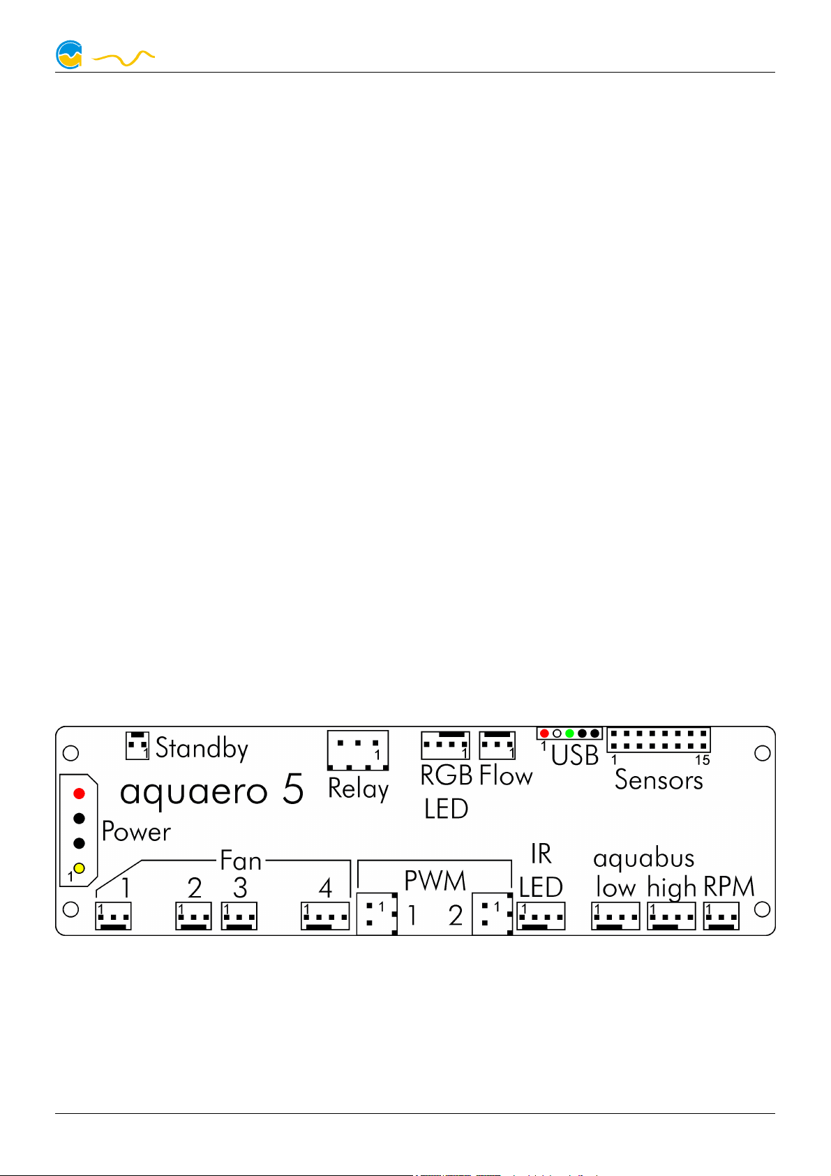
4.1. Connector overview
4.1. Connector overview
4.1. Connector overview4.1. Connector overview
The following schematic shows the connectors of the aquaero 5/6 units:
© 2014-2016 Aqua Computer GmbH & Co. KG - 7 -
Gelliehäuser Str. 1, 37130 Gleichen

AQUAERO 5/6
computeraqu
a
4.2. Connector “Power”
4.2. Connector “Power”
4.2. Connector “Power”4.2. Connector “Power”
Please connect a HDD power plug of your PSU to this connector. Do not use
excessive force but double check the polarity of the plug if you are having
trouble to connect.
Pin assignment: Pin 1 +12 V
Pin 2 GND
Pin 3 GND
Pin 4 +5 V
4.3. Connector “Fan 1/2/3/4”
4.3. Connector “Fan 1/2/3/4”
4.3. Connector “Fan 1/2/3/4”4.3. Connector “Fan 1/2/3/4”
Voltage regulated fan outputs with speed signal processing.
aquaero 5:
Maximum output power is 19.8 W (1.65 A at 12 V) for each channel. Maximum power is dynamically limited through temperature monitoring and will
decrease considerably at lower output voltages. In case an output amplifier
temperature rises to ca. 95 °C, the output is set to 100 % power. After cooling down to ca. 70 °C, normal operation will resume. If the temperature rises to ca. 100 °C, the output will be permanently disabled. To reactivate the
output, the aquaero (or the complete PC) has to be disconnected from
power for a short period of time. Despite this overload protection, the fan
outputs are not short-circuit proof!
Special feature “Fan 4”:
Special feature “Fan 4”: This connector can be used for conventional fans
Special feature “Fan 4”:Special feature “Fan 4”:
→ →or PWM controlled fans. For PWM fans, select “Outputs” “Fans” “Fan
4” from the menu and set “Control mode” to “PWM controlled”.
- 8 - Aqua Computer GmbH & Co. KG © 2014-2016
Gelliehäuser Str. 1, 37130 Gleichen

AQUAERO 5/6
computeraqu
a
aquaero 6:
Maximum current is 2.5 A per output independent of output voltage, resulting in a maximum power of 30 W at 12 V. Outputs will be switched of if
amplifier temperatures reach a critical level and will automatically be reactivated when cooled down. If an output current of 3 A is exceeded, the output will be permanently disabled. To reactivate the output, the aquaero (or
the complete PC) has to be disconnected from power for a short period of
time. The fan outputs are short-circuit proof.
All fan connectors can be used for conventional fans or PWM controlled
→ →fans. For PWM fans, select “Outputs” “Fans” “Fan 1-4” from the menu
and set “Control mode” to “PWM controlled”.
Special feature “Fan 1”:
Special feature “Fan 1”: This connector can alternatively be connected to a
Special feature “Fan 1”:Special feature “Fan 1”:
→flow sensor. If connected to a flow sensor, select “Sensors” “Flow sensors”
→ “Flow 2” from the menu and set “Mode” to “Fan 1 = Flow sensor”.
Pin assignment: Pin 1: GND
Pin 2: 0-12 V
Pin 3: Speed signal
Pin 4: PWM signal (aquaero 5: Fan 4 only)
4.4. Connector “PWM 1/2”
4.4. Connector “PWM 1/2”
4.4. Connector “PWM 1/2”4.4. Connector “PWM 1/2”
Pulse width modulated 12 V outputs, maximum current load 1 A, carrier frequency 15 kHz. Suitable for example for 12 V LEDs, not compatible with
PWM fans or pumps.
Pin assignment: Pin 1: VCC
Pin 2: GND
4.5. Connector „IR LED“
4.5. Connector „IR LED“
4.5. Connector „IR LED“4.5. Connector „IR LED“
Connector for an infrared transmitter LED. This output is not yet functional
with firmware version 2007 and will be activated with an forthcoming
firmware update.
Pin assignment: Pin 1: GND
Pin 2: +12 V
Pin 3: Signal
Pin 4: +5 V
© 2014-2016 Aqua Computer GmbH & Co. KG - 9 -
Gelliehäuser Str. 1, 37130 Gleichen

AQUAERO 5/6
computeraqu
a
4.6. Connector “aquabus low speed/high speed”
4.6. Connector “aquabus low speed/high speed”
4.6. Connector “aquabus low speed/high speed”4.6. Connector “aquabus low speed/high speed”
Connectors for communication with other devices from Aqua Computer. The
aquaero 5/6 features one „low speed“ (aquabus 1) and one „high speed“
(aquabus 2) port.
Products compatible to the “low speed” port:
● Port disabled since firmware version 2000, currently no supported de-
vices.
Products compatible to the “high speed” port:
● aquastream ULTIMATE
● aquastream XT
● Aqua Computer D5 pump motor with aquabus interface
● flow sensor „high flow USB“
● flow sensor mps flow
● poweradjust 2/3 USB (firmware version 1003 or higher)
● farbwerk
● aqualis XT series
● aquainlet XT series
● pump adapter for aqualis with integrated fill level sensor
● pressure sensor mps pressure
Please note: Both aquabus connectors are also compatible with 3 pin
aquabus devices. The additional “pin 4” supplies power to compatible 4 pin
aquabus devices. For example, a poweradjust 3 unit (3 pin) and a mps flow
200 unit (4 pin) can simultaneously be connected using a 4 pin Y adapter
cable (art. 53124).
Pin assignment: Pin 1: GND
Pin 2: SDA
Pin 3: SCL
Pin 4: +5 V
4.7. Connector „RPM/Tacho“
4.7. Connector „RPM/Tacho“
4.7. Connector „RPM/Tacho“4.7. Connector „RPM/Tacho“
Depending on configuration, the aquaero 5/6 can generate a speed signal
which is available for processing through this connector. This speed signal
can for example be configured to cease function upon alarm events and
thereby relay the alarm status to a fan connector of your motherboard. Functionality of the speed signal can be configured using the menu entries
“Alarm” and “Timer”. For details on how to configure your motherboard to
process the speed signal, please refer to the manual of your motherboard.
- 10 - Aqua Computer GmbH & Co. KG © 2014-2016
Gelliehäuser Str. 1, 37130 Gleichen

AQUAERO 5/6
computeraqu
a
4.8. Connector „Sensors“
4.8. Connector „Sensors“
4.8. Connector „Sensors“4.8. Connector „Sensors“
Connector for up to 8 temperature sensors. For compatible sensors, please
refer to chapter 4.14.
Pin assignment: Pin 1/2: Sensor 1
Pin 3/4: Sensor 2
Pin 5/6: Sensor 3
Pin 7/8: Sensor 4
Pin 9/10: Sensor 5
Pin 11/12: Sensor 6
Pin 13/14: Sensor 7
Pin 15/16: Sensor 8
4.9. Connector „USB“
4.9. Connector „USB“
4.9. Connector „USB“4.9. Connector „USB“
This connector is used for USB communication to the PC and for standby
power supply. Take special care to make sure the pin alignment matches
your motherboard!
Pin assignment: Pin 1 +5 V (red)
Pin 2 D- (white)
Pin 3 D+ (green)
Pin 4 GND (black)
Pin 5 not connected
4.10. Connector „Flow“
4.10. Connector „Flow“
4.10. Connector „Flow“4.10. Connector „Flow“
Connector for a flow sensor. Use sensors and cables specified by Aqua Computer only!
Pin assignment: Pin 1: GND
Pin 2: 5 V
Pin 3: Speed signal
4.11. Connector „RGB LED“
4.11. Connector „RGB LED“
4.11. Connector „RGB LED“4.11. Connector „RGB LED“
Connector for up to three LEDs or one two-color or RGB illumination module
(not included in delivery). High brightness LEDs (2-3.2 V, 20 mA) may be
connected without series resistor, a series resistor is built into the aquaero.
Pin assignment: Pin 1: VCC LED 1 (red, for 2.1 V forward voltage)
Pin 2: VCC LED 2 (green, for 3.2 V forward voltage)
© 2014-2016 Aqua Computer GmbH & Co. KG - 11 -
Gelliehäuser Str. 1, 37130 Gleichen

AQUAERO 5/6
computeraqu
a
Pin 3: GND
Pin 4: VCC LED 3 (blue, for 3.2 V forward voltage)
4.12. Connector „Relay“
4.12. Connector „Relay“
4.12. Connector „Relay“4.12. Connector „Relay“
Floating contact (changeover contact). May be used for emergency shutdown
of the PC which requires additional accessories (art. no. 53047 and 53080,
not included in delivery) or for free use. Maximum contact rating 1 A, 12 V.
Pin assignment aquaero 5: Pin 1: normally open
Pin 2: normally connected
Pin 3: common connector
Pin assignment aquaero 6: Pin 1: normally connected
Pin 2: normally open
Pin 3: common connector
4.13. Connector
4.13. Connector „Standby“ (aquaero 5 only)
4.13. Connector4.13. Connector
„Standby“ (aquaero 5 only)
„Standby“ (aquaero 5 only) „Standby“ (aquaero 5 only)
Connector for additional power supply from the 5 Volts standby power line of
the power supply unit. If connected to standby power, the aquaero 5 will remain functional while the computer is in soft off state even if no USB standby
power is supplied. For use with Aqua Computer article number 53047 only
(not included in delivery)!
Pin assignment: Pin 1: GND
Pin 2: +5 V Standby
4.14. Compatible optional accessories for the
4.14. Compatible optional accessories for the aquaero 5/6
4.14. Compatible optional accessories for the 4.14. Compatible optional accessories for the
● aquaremote infrared remote control (article no. 53088, not compatible
aquaero 5/6
aquaero 5/6aquaero 5/6
with aquaero 5/6 LT!)
● poweradjust 3 USB (article no. 53166/53167)
● aquastream ULTIMATE (article no. 41108)
● aquastream XT (article no. 41059/41060/41061)
● Aqua Computer D5 pump motor with USB and aquabus interface (arti-
cle no. 41093)
● Flow sensor (article no. 53061)
● Flow sensor „high flow“ (article no. 53068)
● Flow sensor “high flow USB” (article no. 53129)
● Flow sensor cable (article no. 53027/53100)
● mps flow 100/200/400 (article no. 53130/53131/53132)
- 12 - Aqua Computer GmbH & Co. KG © 2014-2016
Gelliehäuser Str. 1, 37130 Gleichen

AQUAERO 5/6
computeraqu
a
● mps pressure ∆40/∆100/∆500/1000/∆1000 (article no. 53133/
53134/53135/53136/53160)
● farbwerk (article no. 53170/53207)
● Real Time Clock module (article no. 53127)
● Temperature sensor (article no. 53026)
● plug&cool temperature sensor (article no. 53025)
● Temperature sensor inline G1/4 (article no. 53066)
● Temperature sensor internal/external thread G1/4 (article no. 53067)
● Temperature sensor G1/4 (article no. 53147)
● RGB illumination module (article no. 34930)
● aquaero power connect - 24 pin ATX standby power / ATX break (arti-
cle no. 53047)
● Plug for relay connector, 3 contacts (article no. 53080)
● Plug for PWM connector, 2 contacts (article no. 53036)
● aquabus / speed signal cable 3 pin (article no. 93111/53161)
● aquabus Y adapter 3 pin (article no. 53063)
● aquabus cable 4 pin (article no. 53122/53162)
● aquabus Y adapter 4 pin (article no. 53124)
● Water cooler for aquaero 5, G1/4 (article no. 53093, aquaero 5 only)
● Passive heat sink for aquaero 5 (article no. 53094, aquaero 5 only)
● Passive heat sink for aquaero 6 (article no. 53158/53164, aquaero 6
only)
● Acrylic glass display cover for aquaero 5/6 PRO (article no. 53159)
5. Operation of the aquaero 5/6 device
5. Operation of the aquaero 5/6 device
5. Operation of the aquaero 5/6 device5. Operation of the aquaero 5/6 device
Depending on the variant, the aquaero 5/6 can be operated and configured
via USB connection, by using keys and display of the device itself or by using
the aquaremote infrared remote control.
5.1. Operation via USB connection
5.1. Operation via USB connection
5.1. Operation via USB connection5.1. Operation via USB connection
The aquaero 5/6 can be connected to a PC via USB interface and can then
be configured using the aquasuite software. Comprehensive visualization and
logging options are also available in the aquasuite software. The aquasuite
software can be used with any aquaero 5/6 variant (XT, PRO and LT).
Additionally, the aquaero can send keyboard and/or mouse input events to
the PC (depending on variant). During USB initialization, the aquaero 5/6
© 2014-2016 Aqua Computer GmbH & Co. KG - 13 -
Gelliehäuser Str. 1, 37130 Gleichen

AQUAERO 5/6
computeraqu
a
will not only register as an aquaero 5/6 device, but also as a keyboard, a
mouse, a multimedia device and as a infrared receiver. For example, the
aquaremote infrared remote control can be used as a keyboard and mouse
replacement for the PC.
5.2. Operation without USB connection
5.2. Operation without USB connection
5.2. Operation without USB connection5.2. Operation without USB connection
In general, all aquaero 5/6 variants can be used without USB connection to
a PC, all settings are saved in the device itself and all temperature control
processes are autonomously run by the micro processor in the device. Solely
the aquaero LT variant requires a USB connection during configuration, the
USB interface can be disconnected once the aquaero is configured. However, a permanent USB connection to the PC is recommended for power supply
during standby of the PC to keep the clock and calendar of the aquaero up
to date.
5.3. Operation via keys and display (aquaero 5/6 PRO and XT only)
5.3. Operation via keys and display (aquaero 5/6 PRO and XT only)
5.3. Operation via keys and display (aquaero 5/6 PRO and XT only)5.3. Operation via keys and display (aquaero 5/6 PRO and XT only)
Both aquaero 5/6 PRO and aquaero 5/6 XT are equipped with a LC display
and keys and can be configured using these. Both variants provide three keys
to the right of the display, the aquaero 5/6 XT additionally provides four programmable keys below the display.
The upper and lower key on the side of the display will select information
pages during display mode and select and alter menu entries. The middle
key on the side will open the device menu while in display mode and confirm
selected menu entries or values.
The four additional keys below the display of aquaero 5/6 XT units speed up
navigation through the menu. In display mode, the keys are pre-configured
to select certain information pages. Key functions and labels can be assigned
by the user, the keys can be configured to provide quick access to any menu
entry or information page.
During configuration via keys and display, the aquasuite software should be
closed on a connected PC! Otherwise, the aquasuite will overwrite and thereby cancel any settings made on the device itself.
Notice: The RGB color controllers can not be configured using the device
display. Please use an USB connection and the aquasuite software to configure the RGB controllers.
- 14 - Aqua Computer GmbH & Co. KG © 2014-2016
Gelliehäuser Str. 1, 37130 Gleichen
AQUAERO 5/6
computeraqu
a
5.4. Operation via aquaremote (aquaero 5/6 PRO and XT only)
5.4. Operation via aquaremote (aquaero 5/6 PRO and XT only)
5.4. Operation via aquaremote (aquaero 5/6 PRO and XT only)5.4. Operation via aquaremote (aquaero 5/6 PRO and XT only)
Both aquaero 5/6 PRO and aquaero 5/6 XT are equipped with an infrared
receiver and can be operated using the aquaremote infrared remote control.
The aquaremote is included in delivery of the aquaero 5/6 XT and can be
bought separately for the aquaero 5/6 PRO.
Depending on current aquaero configuration, infrared commands received
by the aquaero will either be processed for aquaero operation or forwarded
as keyboard and mouse events to the PC via USB. For details, please refer to
the next chapter.
5.5. Configuration menu (aquaero 5/6 PRO and XT only)
5.5. Configuration menu (aquaero 5/6 PRO and XT only)
5.5. Configuration menu (aquaero 5/6 PRO and XT only)5.5. Configuration menu (aquaero 5/6 PRO and XT only)
In display mode, the configuration menu can be accessed by pressing the
middle side key or the “OK” key on the aquaremote remote control. The
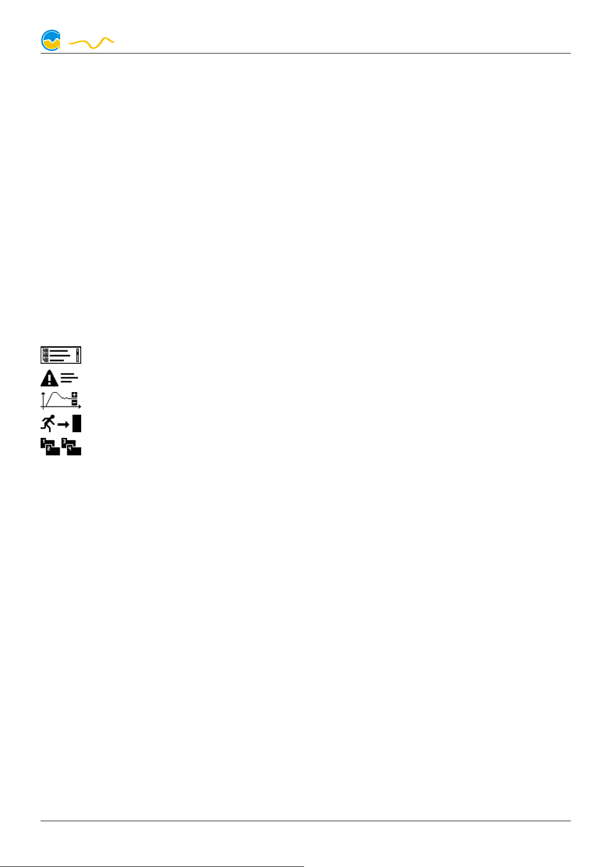
symbols of the configuration menu will access the following functions:
Access full menu listing.
Show event list.
Jump to sub-menu “Controllers”.
Exit configuration menu.
Activate profile 1/2/3/4.
The menu listing is dynamically assembled depending on aquaero variant
(LT, PRO or XT) and connected sensors and expansion boards. For instance,
the sub-menu “Sensors”/”Temperature sensors” will only show sensors currently connected to the aquaero, while adding a poweradjust expansion
board via aquabus will instantly show an addition fan output in the sub-menu
“Outputs”/”Fans”.
6. Infrared remote control aquaremote
6. Infrared remote control aquaremote
6. Infrared remote control aquaremote6. Infrared remote control aquaremote
The infrared remote control aquaremote can be used with any aquaero 5/6
XT or aquaero 5/6 PRO device. The infrared receiver is located left of the
display of the aquaero. The aquaero 5 LT is not equipped with an infrared
receiver and can therefore not be controlled by aquaremote.
© 2014-2016 Aqua Computer GmbH & Co. KG - 15 -
Gelliehäuser Str. 1, 37130 Gleichen
AQUAERO 5/6
computeraqu
a
6.1. Modes of operation “aquaero”, “PC keyboard”, “PC media keys”
6.1. Modes of operation “aquaero”, “PC keyboard”, “PC media keys”
6.1. Modes of operation “aquaero”, “PC keyboard”, “PC media keys”6.1. Modes of operation “aquaero”, “PC keyboard”, “PC media keys”
Processing of infrared commands received by the aquaero depends on current mode of operation. Some keys have different functions assigned in the
three modes of operation.
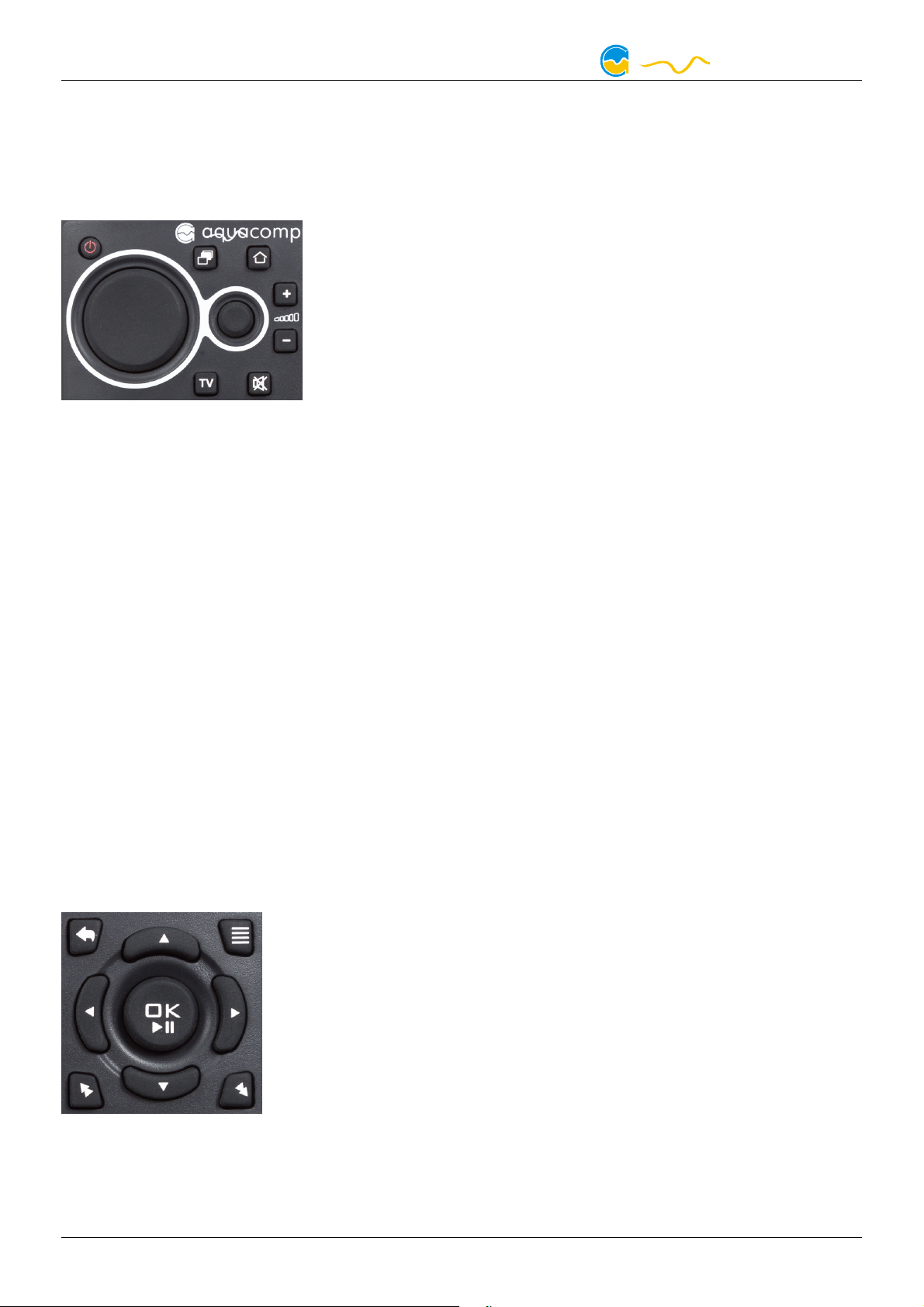
In “aquaero” mode, all keys will be processed by the
aquaero and not forwarded to the PC. In “PC keyboard” and “PC media keys” mode, all keys will directly be forwarded to the PC and not be processed
by the aquaero.
All modes of operation can be consecutively selected
by pressing the “” key, alternatively the “aquaero”
mode can be selected by pressing the “” key and the “PC media keys”
mode can be selected by pressing the „TV“ key. The circular mouse control
pad and the three keys for volume control are forwarded to the PC in all
modes. Please note that all modes and mouse control pad can be individually activated or deactivated in the aquaero, see chapter 19.1. for details. Deactivated modes can not be selected and corresponding keys of the remote
control are not operational!
The currently selected mode is displayed on the aquaero display for approximately two seconds after switching modes. Additionally, in “PC keyboard”
mode and in “PC media keys” mode, a “PC” label will be permanently displayed in the lower right corner of the display.
In all modes, the “” key toggles between lower and upper characters and
the “Alt” (green) and “Alt” (blue) keys activate and deactivate the numbers
and special characters printed in the corresponding colors.
6.2. Special functions in “aquaero” mode
6.2. Special functions in “aquaero” mode
6.2. Special functions in “aquaero” mode6.2. Special functions in “aquaero” mode
Exit menu
↖ One menu level up
≣ Show event list
Previous
Next
OK Enter menu/confirm
No function
During display mode, the keys „QWER“ correspond to the four programmable function keys. The remaining keys will display the configured information pages („T“ first page, „Y“ second page, ...).
- 16 - Aqua Computer GmbH & Co. KG © 2014-2016
Gelliehäuser Str. 1, 37130 Gleichen
 Loading...