

Page 1
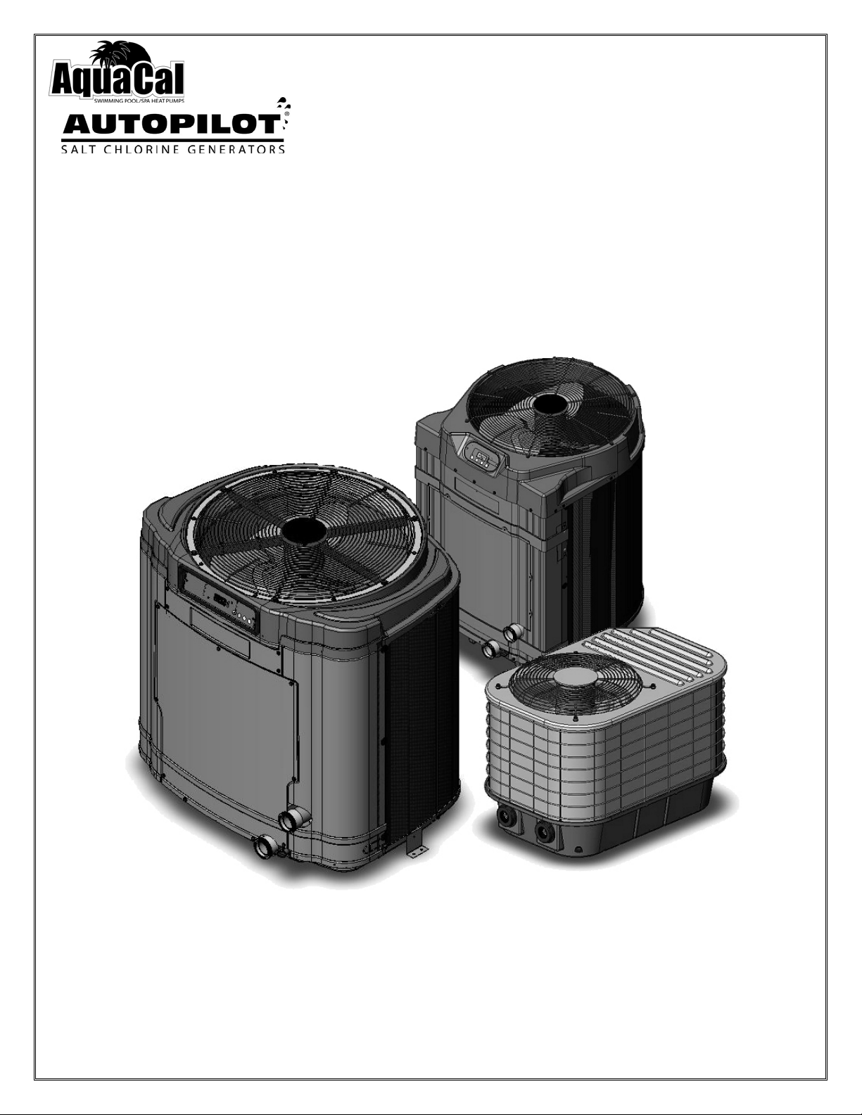
Heat Pump
Quick Start Guide
Models: 035, 055, 075, 110, 120, 121, 155, 156, & 175
For product manuals and further installation / operation procedures
visit www.AquaCal.com
Important
Read This Guide Before Installing or Operating Heat Pump
LTP0055 Rev-3 02/01/2011
Page 2
Page 1
SECTION 1 - GENERAL INFORMATION
CONTACTING AQUACAL AUTOPILOT
Web www.AquaCal.com
Phone
Fax (727) 821-7471
(727) 823-5642
8:00 a.m. to 5:00 p.m. Eastern time, Monday through Friday
If you should need to call AquaCal AutoPilot for questions, service, or parts, please have your model and serial
numbers available.
SAFETY
For personal safety, and to avoid damage to equipment, follow all safety instructions displayed in this guide. Repair
and service of your heat pump must be performed by qualified service personnel. Failure to properly install, operate,
maintain, or repair the heat pump will void factory warranty. Safety signals are placed where particular attention is
required. Please note "WARNING" signals relate to personal safety, while "CAUTION” signals promote avoiding
damage to equipment.
Follow all National Electric Codes (NEC) unless State or Local guidelines supersede. When installing and using your
heat pump, basic safety precautions must always be followed, including the following:
WARNING - Failure to heed the following may result in injury or death.
Heat pumps contain no owner-repairable components.
Electrical Installation should be by Licensed Electrician only.
Service to the refrigerant circuit must be performed only by qualified HVAC Technicians.
Heat pumps utilize high voltage and rotating equipment. Use caution when servicing.
Heater contains refrigerant under pressure. Recover refrigerant before opening system.
Prolonged immersion in water warmer than normal body temperature can cause fatal Hyperthermia.
The use of alcohol, drugs, or medication can greatly increase the risk of fatal Hyperthermia.
Persons having an adverse medical history, or pregnant women, should consult a physician before
using a hot tub or spa. In addition, children and the extreme elderly should be supervised by a
responsible adult.
CAUTION - Failure to heed the following may result in equipment damage.
Improper water chemistry can cause damage to pump, filter, pool shell, etc. To avoid equipment
damage, maintain Pool/Spa water per standards detailed later in this manual.
Water flow exceeding 70-GPM requires a bypass. Damage due to excessive water flow will void
warranty.
SAVE THESE INSTRUCTIONS
SPECIFICATIONS
Specification Description
Water Flow
Requirements
Electrical Service See data plate attached to front cover or behind front access panel on equipment.
30 - 55 gallons per minute (gpm) ideal range. A heater bypass is required for water flow greater than 70 gpm.
AGENCY APPROVALS
Agency Description
NEC NFPA No. 70, and all applicable state codes
NEC Article 680, Swimming Pools, Fountains, and Similar Installations
NEC Article 440, Air-Conditioning and Refrigeration Equipment
ETL UL 1995
Table 1
Table 2
Page 3
Page 2
SECTION 2 - INSTALLATION
For commercial or complete installation instructions please, visit www.AquaCal.com for equipment manual.
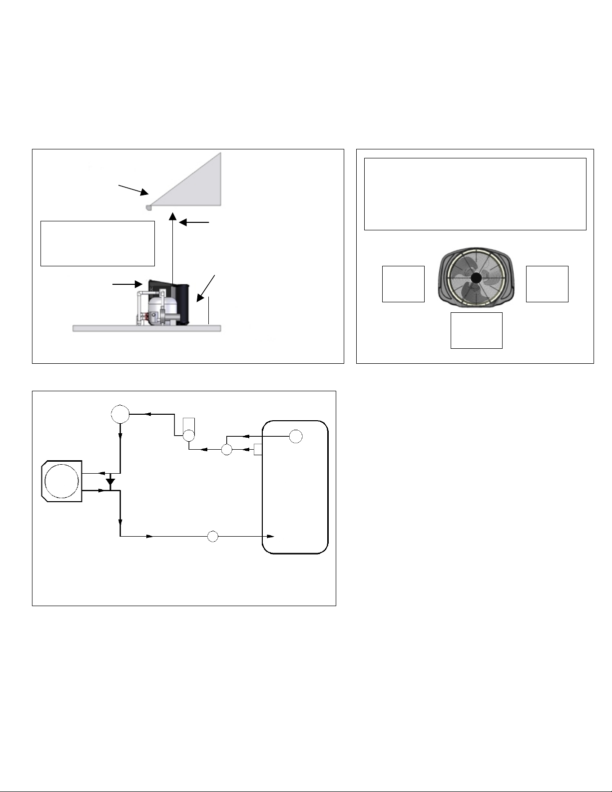
EQUIPMENT CLEARANCES
Keep the area immediately adjacent to the heat pump clear of items such as shrubs and bushes, lawn furniture,
chemicals containers, etc. These items can prevent air from circulating properly through the heater, and will result in
inefficient operation and/or damage to the heat pump.
Overhang with
Gutter
5 feet Minimum Clearance
Rain Run-Off Must Be
Directed Away From
Heater
(Front)
30” Minimum
Clearance
Overhead
(Rear)
12” Clearance for all
IceBreaker / Heat &
Cool Models
12” Clearance for All
Tropical Models
6” Clearance for SQ
“Heat Only” Models
Figure 1 Figure 2
12” Clearance for All IceBreaker / Heat &
Cool Models
12” Clearance for All TropiCal Models
6” Clearance for SQ “Heat Only” Models
(Side)
12”
(Rear)
(Side)
12”
(Front)
30”
PLUMBING SCHEMATIC
F
P
D
3 S
H
Figure 3
B
C
POOL
R
3 = Three Way Valve
B = Bypass Check Valve (5lb) for Water Flow
Over 70 GPM
C = Chlorinator
D = Main Drain
F = Filter
H = Heat Pump
P = Water Pump
R = Return
S = Skimmer
ELECTRICAL REQUIREMENTS
1) Locate the equipment power disconnect within 6-feet of the heater’s electrical enclosure.
2) Never mount power disconnects directly to heat pump.
3) Only use copper conductors.
4) Use sequencing controllers when multiple heaters are installed on site.
5) Local codes and regulations may require the use of a ground fault interruption device (GFI Circuit Breaker).
Nuisance tripping of these devices is common and not covered under the terms of the Manufacturer’s warranty.
6) Review online product manual when connecting external controller devices to heat pump.
Page 4
Page 3
SECTION 3 - OPERATION
Pool
Spa
Cooling
POOL
SPA
78°
UP
DOWN MODE
Desired Temp
Water Temp
Heating
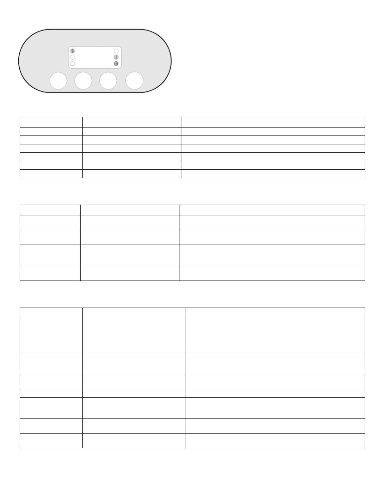
Figure 4
INDICATOR LIGHTS
LIGHTS EXPLANATION SUPPLEMENTAL INFORMATION
“Pool” Pool Thermostat Selected
“Spa” Spa Thermostat Selected
“Cooling” Actively Cooling Water Not applicable for Straight Heat models.
“Desired Temp” Setting Desired Water Temperature
“Water Temp” Actual Water Temperature
“Heating” Actively Heating Water
BUTTONS
BUTTONS EXPLANATION SUPPLEMENTAL INFORMATION
“Pool / Spa” Select between Pool and Spa Please note – this does not turn off equipment. It only allows a user to
toggle between the Pool thermostat and the Spa thermostat.
“Up” Select to raise temperature set
point or move up in a menu choice
“Down” Select to lower temperature set
point or move down in a menu
choice
“Mode” Select a mode Modes available are “ACH”, “COOL”, “HEAT”, and “OFF”.
Please note – “ACH” and “COOL” only available on some models.
Table 3
DISPLAY
MESSAGE EXPLANATION SUPPLEMENTAL INFORMATION
“000”
“ACH” Auto-Change Over Mode
“COOL” Cooling Mode
“HEAT” Heating Mode Heat Pump is set to heat water.
“OFF” Unit off
“xx°”
FLO No water flow through Heat Pump
A user lockout code has been
activated.
Current Water Temperature
(Example 78°)
Table 4
A numeric code is required before any temperature adjustment can
be entered. Use the “UP” or “DOWN” arrow to enter code, then select
“MODE” to temporarily unlock Heat Pump. If code is unknown, a reset option is available in product manual. Manuals can be
downloaded from www.AquaCal.com.
When this mode is active, the heat pump will automatically switch
between heating and cooling modes to maintain a set temperature
point within
Heat Pump is set to cool the water. Feature available for Heat & Cool
units.
Heat Pump can be turned off by using “MODE” button or setting
temperature below 45 degrees. Heat Pump will not allow a set
temperature to be programmed until turned on again.
Temperature can be set from 45° F to 104° F. This can be displayed
in Fahrenheit or Celsius depending on programming.
This can be a normal display depending on system settings. See
“Troubleshooting” if needed.
3 degrees. Feature available for Heat & Cool units.
Table 5
Page 5
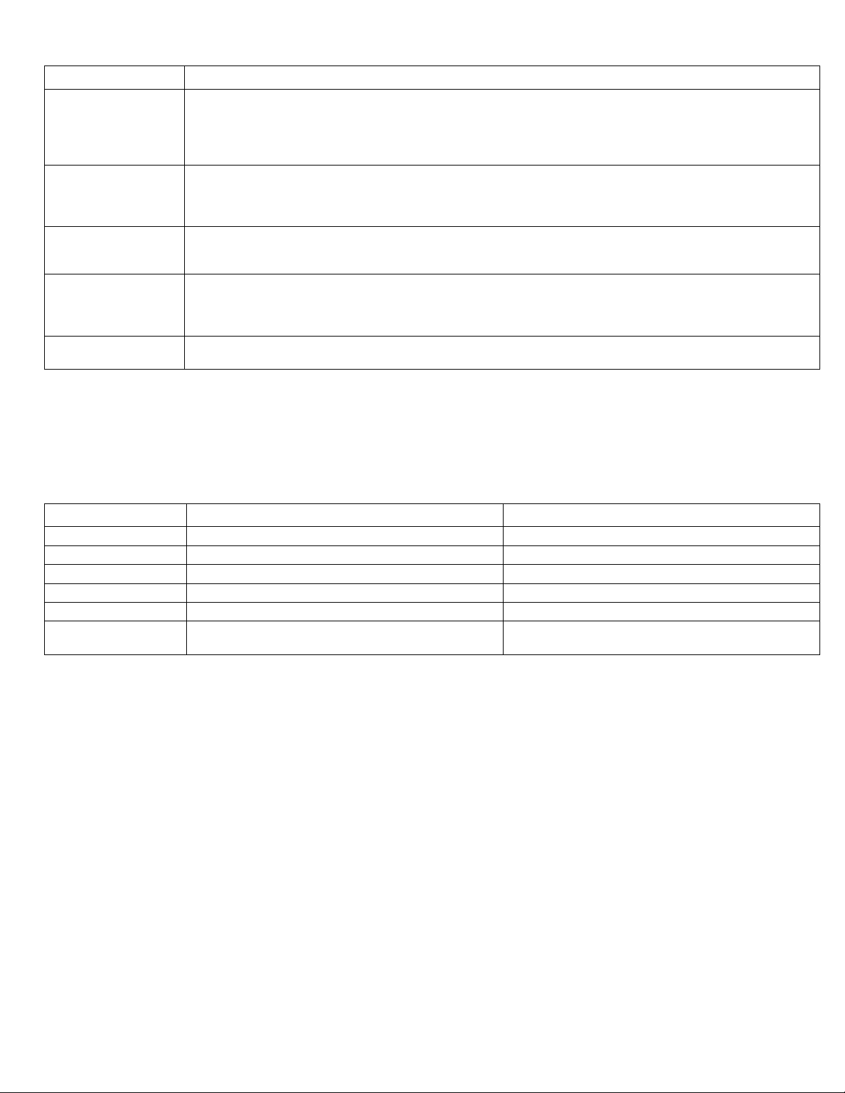
PROGRAMMING
Activity Steps
Step 1: Select the “POOL / SPA” button to choose the thermostat to adjust.
Adjusting
Temperature
Turning Heat Pump
“ON”
Turning Heat Pump
“OFF”
Setting to “Celsius”
or “Fahrenheit”
Switching from Pool
to Spa
Step 2: Select the “UP” or “DOWN” button to increase or decrease the desired set temperature.
Step 3: Once set, the current water temperature will be displayed. The Heat Pump will start to operate to meet
the desired temperature. Please note a time delay will be experienced if Heat Pump has just been
initialized. This delay is between 4 to 5 minutes.
Step 1: Confirm Heat Pump has power.
Step 2: Select the “MODE” button.
Step 2: Using the “UP” or “DOWN” arrow, select “ACH”, “COOL”, “HEAT”, or “OFF”. See section on Display
for “MODE” usage.
Step 1: Select the “MODE” button.
Step 2: Using the “UP” or “DOWN” arrow, select “OFF”
Please note – setting temperature below 45° F will also turn off Heat Pump.
Step 1: Select and hold down both the “UP” and “DOWN” arrow keys simultaneously until the Celsius /
Fahrenheit code (CF1) appears on the display.
Step 2: Select the “UP” or “DOWN” arrow to select “1” for Fahrenheit or “2” for Celsius.
Step 3: Allow display to time-out.
Select the “POOL / SPA” button.
SECTION 4 - MAINTENANCE
Page 4
Table 6
POOL CHEMISTRY
Maintain pool water with the following chemical levels. Commercial applications may vary from depending on locale.
All values show in PPM (Parts Per Million).
Chemical Pool Spa
Chlorine 1 to 3 parts per million (PPM) 1.5 to 3 PPM
Bromine 1 to 3 PPM 3 to 5 PPM
pH 7.4 to 7.8 PPM 7.2 to 7.8 PPM
Total Alkalinity 80 to 140 PPM 80 to 120 PPM
Calcium Hardness 200 to 400 PPM 200 to 400 PPM
Total Dissolved
Solids
1,000 to 2,000 PPM 1,500 to 2,000 PPM
Table 7
WINTERIZING
In areas where freezing conditions are a rare occurrence, allow the filtration system to run continuously throughout
the freeze period. Typically, during light freeze conditions, circulating (moving) water will not freeze. In areas where
freezing conditions are prevalent and sustained, the heat pump must be winterized as follows:
1) Disconnect all electrical power to the heater; turn off circulating pump.
2) At the two (2) connection unions, disconnect the plumbing to the heater (removal is counter-clockwise).
3) If your unit has an external drain plug, remove plug. This plug would be located at lower, front corner of
heater (position may vary between models). Allow water to drain out of the condenser. Replace the
winterizing plug by threading the plug in clockwise until just snug, then apply an additional 1/8 turn.
4) If no drain plug is found, unit is self draining from unions. Check online manuals for appropriate winterizing
procedures on heat pumps older than 2005.
5) To prevent insects and vermin from entering the plumbing during the winterized period, partially reconnect
the two (2) plumbing connection unions: couple each union one or two threads; this will permit condensation
to drain, but will prevent most insects and animals from entering the plumbing circuit.
START UP
To ready a winterized heat pump for use, simply retighten plumbing connection unions. Hand-tight is generally
sufficient.
Page 6
Page 5
SECTION 5 - TROUBLESHOOTING
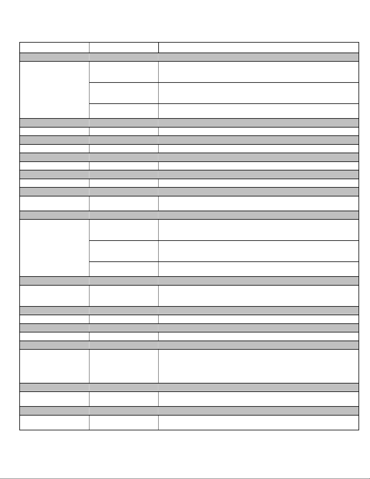
ERROR CODES
SYMPTOM RULE OUT RESOLUTION
"FLO"
Insufficient water flow
through heater or
circulation pump is off
“CEr” Error
Communication Fault N/A Request Service
“CSE” Error
Control System Error N/A Request Service
“dPC” Error
Defrost Sensor Shorted N/A Request Service
“dPO” Error
Defrost Sensor Open N/A Request Service
“FS” Error
Unit in defrost mode.
“HP” Error
High Pressure.
“HP5” Error
Equipment has
registered high pressure
five times and locked.
“LP” Error
Refrigerant Issue N/A Request Service
“LP5” Error
Refrigerant Issue N/A Request Service
“OTA”
Over Temperature
Alarm
Temperature over
110° F (Unit Locked)
“PC” Error
Water Temperature
Sensor Shorted
“PO” Error
Water Temperature
Sensor Open
Insufficient Water Flow
Filtration Dirty
Possible Water
Pressure Switch
Normal defrost mode
Insufficient Water Flow
Filtration Dirty
Possible Refrigerant
Issue
Insufficient Water Flow
and/or Filtration Dirty
Other heating
equipment
N/A Request Service
N/A Request Service
Step 1:
Confirm water pump is on and water valves are in the correct position to allow
water to flow through Heat Pump. If error persists, proceed to next step.
Step 2:
Confirm filtration system is clean. Backwash if needed. If error persists,
proceed to next step.
Step 3:
Request Service
Step 1:
If error persists after air temperature is over 50° F, request service.
Step 1:
Confirm water pump is on and water valves are in the correct position to allow
water to flow through Heat Pump. If error persists, proceed to next step.
Step 2:
Confirm filtration system is clean. Backwash if needed. If error persists,
proceed to next step.
Step 3:
Request Service
Step 1:
Follow steps outlined in “HP” error, then reset circuit breaker to clear error. If
error persists, request service.
Check if alternate heater (such as a solar heater) is heating water leading to
heat pump. If “yes”, turn off alternate heater and check if error clears. If error
persists, request service.
 Loading...