

Page 1

SWIMMING POOL HEAT PUMP UNIT
POMPA DI CALORE PER PISCINA
version 3, release 05th Nov 2017
Page 2

SWIMMING POOL HEAT PUMP UNIT
CONTENTS
1. Preface 1
2. Spec
2.1 Performance Data of Swimming Pool Heat Pump Unit 2
2.2 Dimensions for Swimming Pool Heat Pump Unit 4
3.2 Swimming Pool Heat Pumps Location 10
3.3 How Close to Your Pool? 10
3.4 Swimming Pool Heat Pumps Plumbing 11
3.5 Swimming Pool Heat Pumps Electrical Wiring 12
3.6 Initial Start-up of the Unit 12
4. Usage and Operation
13
4.1 Function of the controller 13
4.2 Usage of the controller
14
4.3 Parameter table 18
4.4 Mulfunction table 19
3. Installation and Connection 9
3.1 Installation of System 9
5. Maintenance and Inspection 20
6.Appendix 21
version 3, release 05th Nov 2017
Page 3
1. PREFACE
In order to provide our customers with quality, reliability and versatility, this product has been
made to strict production standards. This manual includes all the necessary information about
installation, debugging, discharging and maintenance. Please read this manual carefully before
you open or maintain the unit. The manufacture of this product will not be held responsible if
someone is injured or the unit is damaged, as a result of improper installation, debugging, or
unnecessary maintenance. It is vital that the instructions within this manual are adhered to at all
dealer.
Maintenance and operation must be carried out according to the recommended time and
frequency, as stated in this manual.
Use genuine standard spare parts only.
Failure to comply with these recommendations will invalidate the warranty.
Swimming Pool Heat Pump Unit heats the swimming pool water and keeps the temperature
constant. For split type unit, The indoor unit can be Discretely hidden or semi-hidden to suit a
luxury house.
Our heat pump has following characteristics:
1 Durable
The heat exchanger is made of PVC & Titanium tube which can withstand prolonged
exposure to swimming pool water.
The unit can be installed outdoors or indoors. 3
Quiet operation
-noise fan motor,
which guarantees its quiet operation.
4 Advanced controlling
The unit includes micro-computer controlling, allowing all operation parameters to be set.
Operation status can be displayed on the LCD wire controller. Remote controller can be chosen
as future option.
1
version 3, release 05th Nov 2017
Page 4
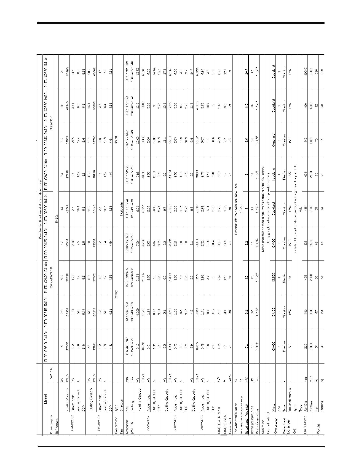
2.SPECIFICATION
2 .1 Perform ance data of Swimming Pool Heat Pump Unit
*** REFRIGERANT : R410A/R407C
2
version 3, release 05th Nov 2017
Page 5
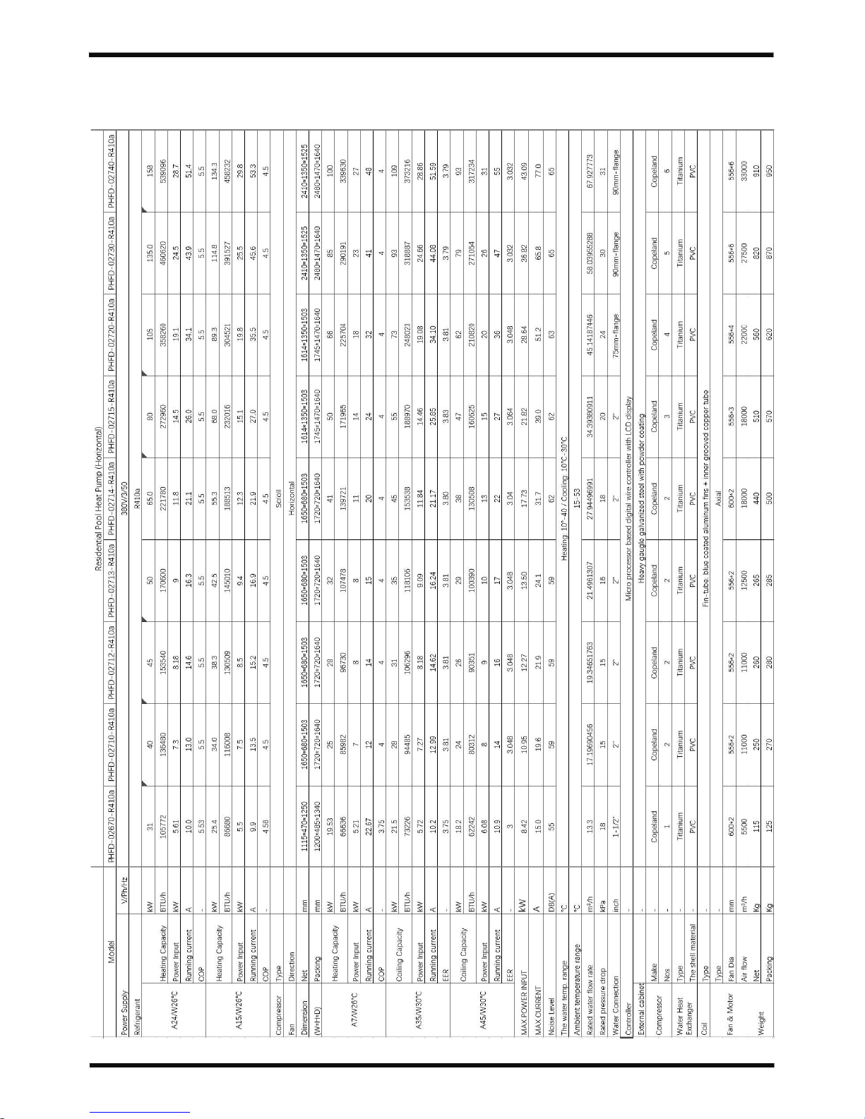
2 .2 Perform ance data of Swimming Pool Heat Pump Unit
*** REFRIGERANT : R410a/R407C
2.SPECIFICATION
3
version 3, release 05th Nov 2017
Page 6
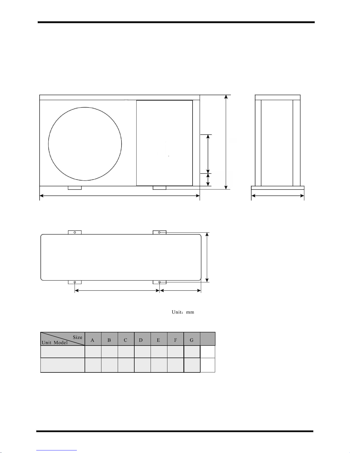
2.SPECIFICATION
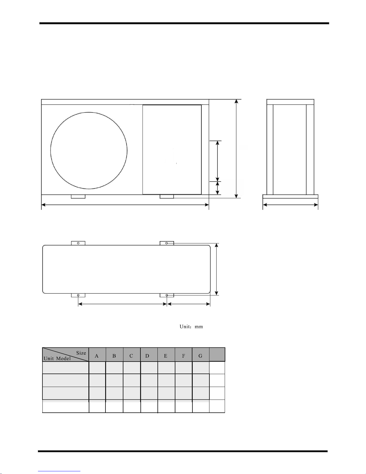
2.2 Dimensions for Swimming Pool Hea t Pump Unit
4
620
G
F
E
77
33 0
PH FD -0 2615
A
C
B
36 010 1064 5
D
20 232 8
PH FD -0 2620
PH FD -0 2625
PH FD -0 2610
77
28 0
36 093 054 5 15 229 8
version 3, release 05th Nov 2017
H
H
62 0
55 0
Page 7
2.SPECIFICATION
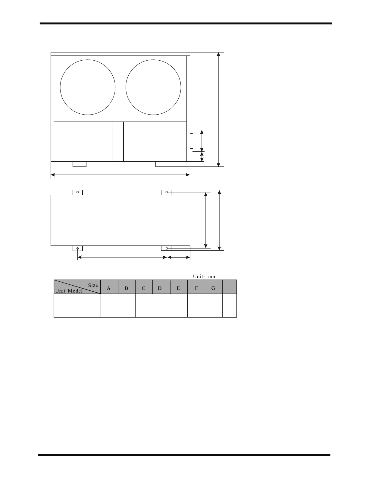
2.2 The dimensions for Swimming Pool Heat Pump Unit
5
version 3, release 05th Nov 2017
620
G
F
E
77
38 0
A
C
B
D
76 0 44 0 1114 17 7 47 0
PH FD -0 2630
PH FD -0 2640
PH FD -0 2645
PH FD -0 2650
PH FD -0 2660
77
50 0
76 0 44 0 1114 17 7 47 0
77
70 0
76 0 44 0 1114 17 7 47 0
H
H
71 0
95 0
12 50
PH FD -0 2670
77
70 0
76 0 54 0 1114 17 7 57 0
12 50
Page 8
2.SPECIFICATION
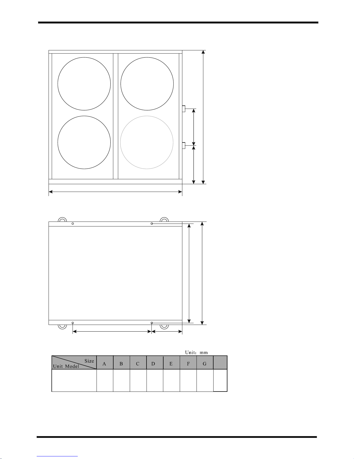
2.2 The dimensions for Swimming Pool Heat Pump Unit
6
G
F
E
A
C
B
D
PH FD -0 2710
PH FD -0 2712
PH FD -0 2713
77
42 0
10 50 6 40 1 65 0 3 00 6 80
version 3, release 05th Nov 2017
H
15 25
H
PH FD -0 2714
Page 9
2.SPECIFICATION
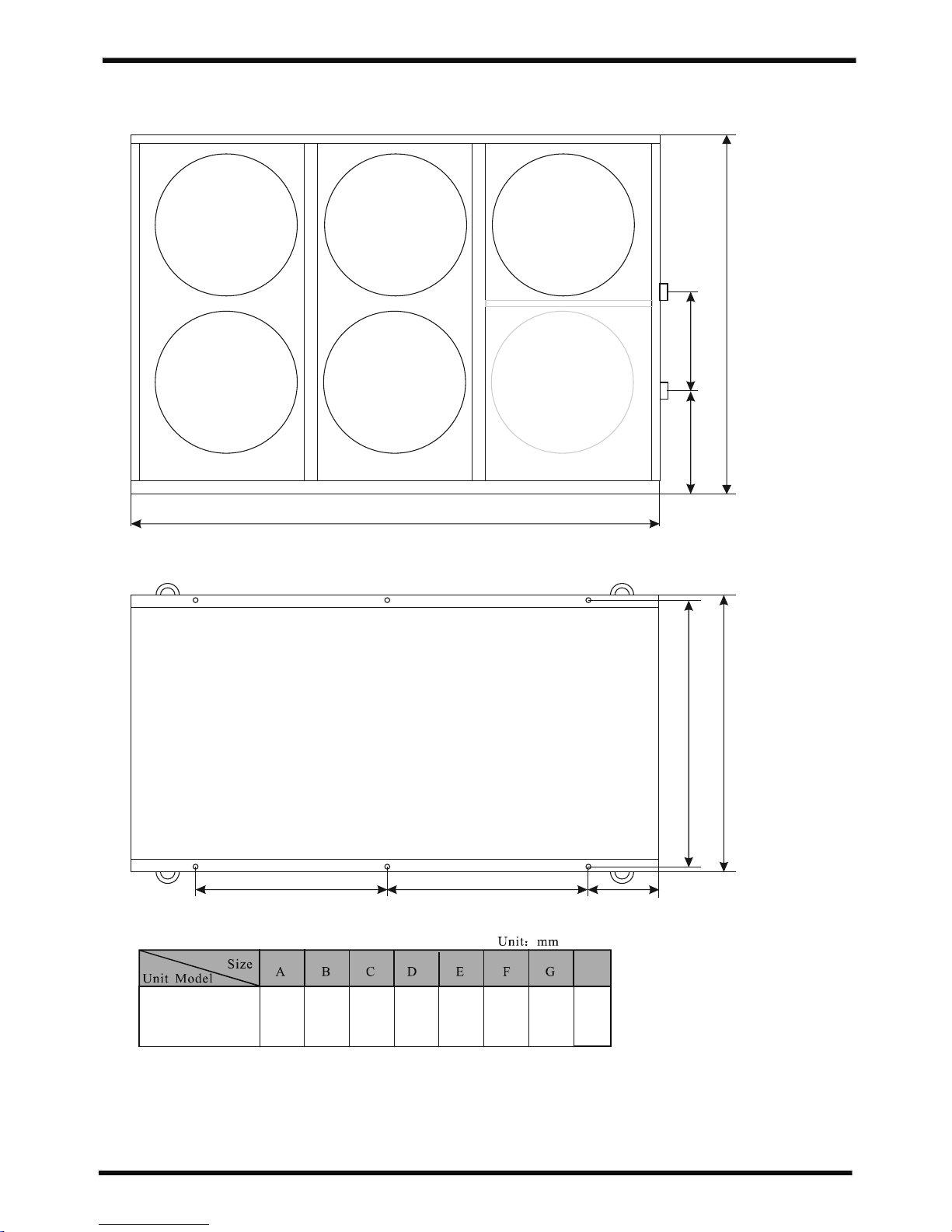
2.2 The dimensions for Swimming Pool Heat Pump Unit
7
G
F
C
PH FD -0 2715
73 0
50 0
10 05 1 27 6 1 61 4 304 135 0
version 3, release 05th Nov 2017
15 25
H
H
E
A
B
D
PH FD -0 2720
Page 10
2.SPECIFICATION
2.2 The dimensions for Swimming Pool Heat Pump Unit
8
G
F
E
A
C
B
D
PH FD -0 2740
73 0
50 0
90 0 12 76 24 10 3 05 1350
A
PH FD -0 2730
version 3, release 05th Nov 2017
15 25
H
H
Page 11
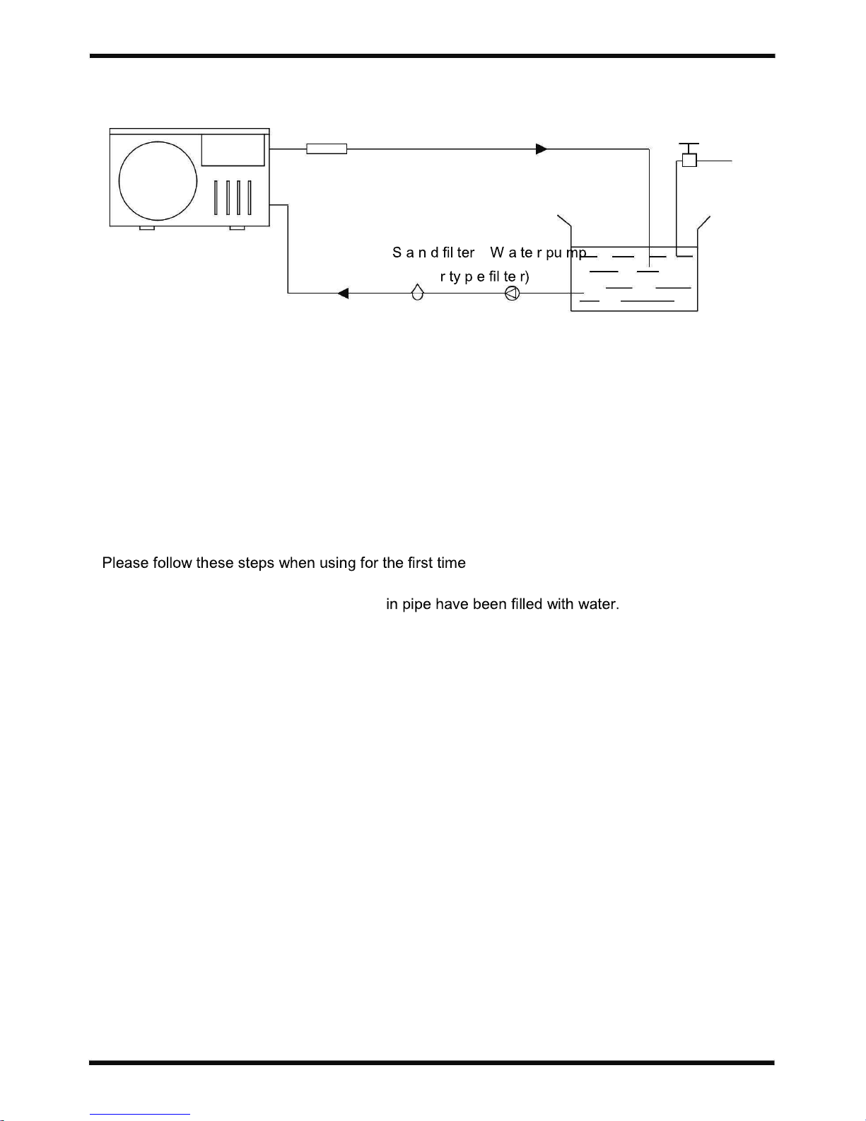
3.INSTALLATION AND CONNECTION
3.1 Installation illustration
W a te r ou tlet
P ool
(o r o th e
Va lve
W a te r s upp ly
Installation items:
The factory only provides the main unit and the water unit; the other items in the illustration are
necessary spare parts for the water system ,that provided by users or the installer.
Attention:
1.Open valve and charge water.
2.Make sure that the pump and the water-
3.Close the valve and start the unit.
The schematic diagram is for reference only. Please check the water inlet/outlet label on the heat
pump while plumbing installation.
9
version 3, release 05th Nov 2017
Page 12
3.INSTALLATION AND CONNECTION
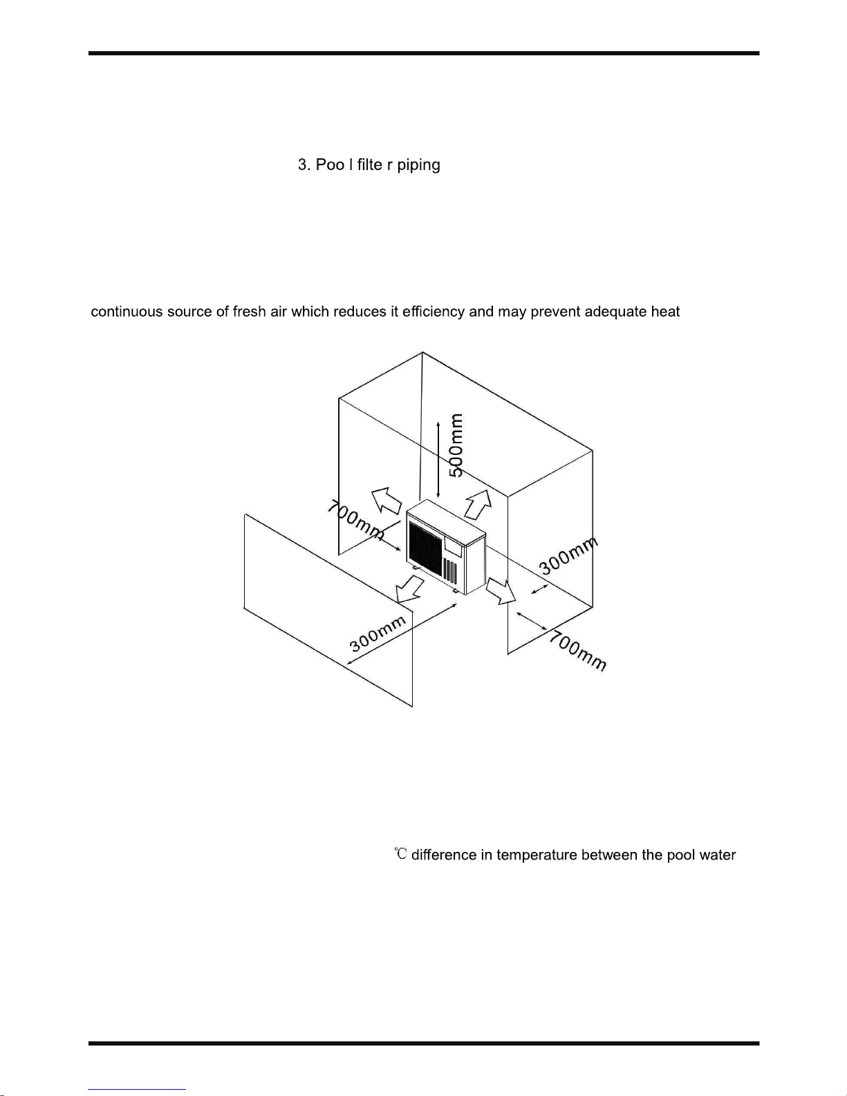
3.2 Swimming Pool Heat Pumps Location
The unit will perform well in any outdoor location provided that the following three factors are
presented:
1 . Fresh Air - 2. Electric ity -
The unit may be installed virtually anywhere outdoors. For indoor pools please consult the
supplier. Unlike a gas heater, it has no draft or pilot light problem in a windy area.
DO NOT place the unit in an enclosed area with a limited air volume, where the units
discharge air will be re-circulated.
DO NOT place the unit to shrubs which can block air inlet. These locations deny the unit of a
delivery.
Air inlet
Air outlet
3.3 How Close To Your Pool?
Normally, the pool heat pump is installed within 5/7 metres of the pool. The longer the distance from
the pool, the greater the heat loss from the piping. For the most part ,the piping is buried. Therefore,
the heat loss is minimal for runs of up to15 meters(15 meters to and from the pump = 30 meters
total), unless the ground is wet or the water table is high. A very rough estimate of heat loss per 30
meters is 0.6 kW-hour,(2000BTU) for every 5
and the ground surrounding the pipe, which translates to about 3% to 5% increase in run time.
10
version 3, release 05th Nov 2017
Page 13
3.INSTALLATION AND CONNECTION
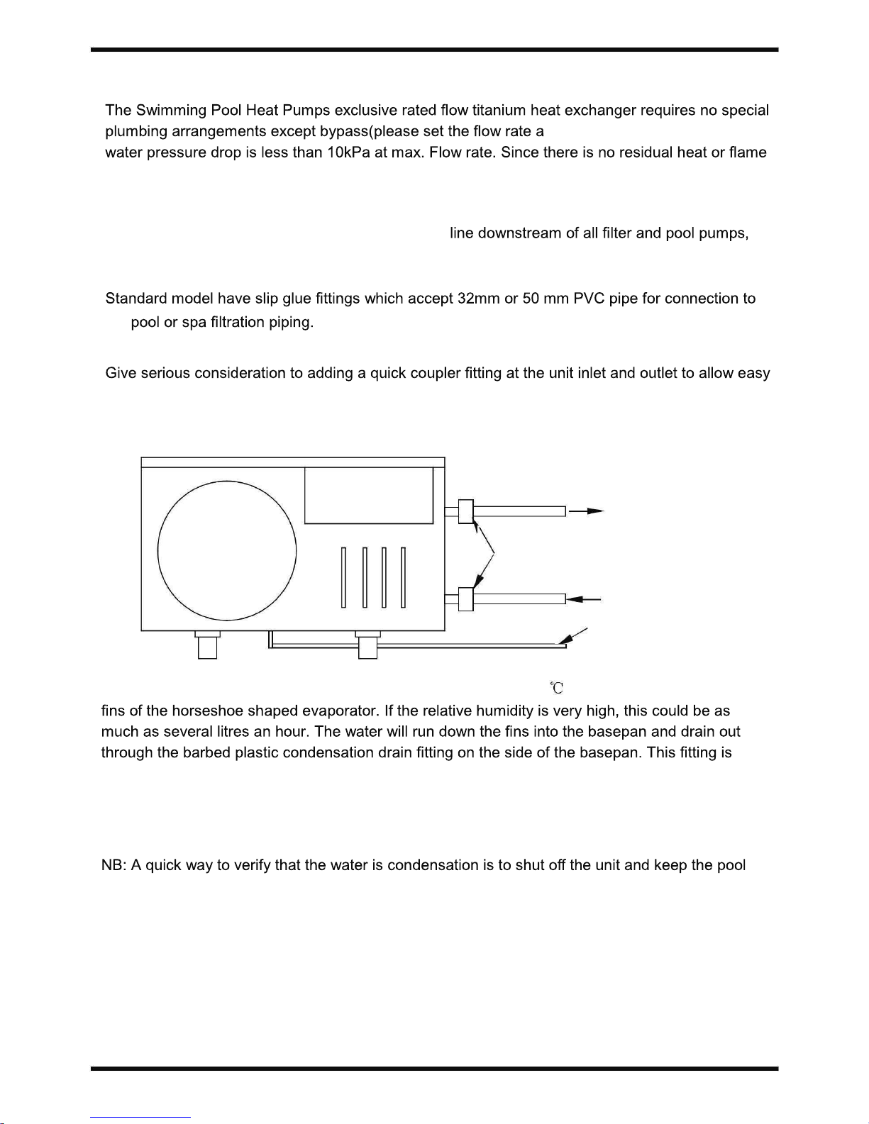
3.4 Swimming Pool Heat Pumps Plumbing
ccording to the nameplate). The
Temperatures, The unit does not need copper heat sink piping. PVC pipe can be run straight into
the unit.
Location: Connect the unit in the pool pump return
and upstream of any chlorinators, ozonators or chemical pumps.
the
draining of unit for winterizing and to provide easier access should servicing be required.
To pool
PVC COUPLER
RECOMMENDED(Provided)
From pump
CONDENSATION
DRAIN
BARB FTG
Condensation: Since the Heat pump cools down the air about 4 -5 , water may condense on the
designed to accept 20mm clear vinyl tubing which can be pushed on by hand and run to a suitable
drain. It is easy to mistake the condensation for a water leak inside the unit.
pump running. If the water stops running out of the basepan, it is condensation. AN EVEN
QUICKER WAY IS to TEST THE DRAIN WATER FOR CHLORINE - if the is no chlorine present,
then it's condensation.
11
version 3, release 05th Nov 2017
Page 14
3.INSTALLATION AND CONNECTION
3.5 Swimming Pool Heat Pumps Electrical Wiring
NOTE: Although the unit heat exchanger is electrically isolated from the rest of the unit, it
required to protect you against short circuits inside the unit. Bonding is also required.
The unit has a separate molded-in junction box with a standard electrical conduit nipple already in
place. Just remove the screws and the front panel, feed your supply lines in through the conduit
nipple and wire-nut the electric supply wires to the three connections already in the junction box
(four connections if three phase). To complete electrical hookup, connect Heat Pump by electrical
ies)
to a dedicated AC power supply branch circuit equipped with the proper circuit breaker,
disconnect or time delay fuse protection.
Disconnect - A disconnect means (circuit breaker , fused or un-fused switch) should be located
within sight of and readily accessible from the unit, This is common practice on commercial and
residential air conditioners and heat pumps. It prevents remotely-energizing unattended equipment
3.6 Initial startup of the Unit
NOTE-
circulate water through the heat exchanger.
Start up Procedure - After installation is completed, you should follow these steps:
1. Turn on your
2. Turn on the electrical power supply to the unit, then press the key ON/OFF of wire
controller, It should start in several seconds.
3. After running a few minutes make sure the air leaving the top(side) of the unit is
cooler(Between 5-10 )
4.
5. Allow the unit and pool pump to run 24 hours per day until desired pool water emperature is
reached. When the waterautomatically restart (as long as your pool pump is running)when the pool temperature drops more
than 2 below set temperature.
Time Delay- The unit is equipped with a 3 minute built-in solid state restart delay included to
protect control circuit components and to eliminate restart cycling and contactor chatter. This time
delay will automatically restart the unit approximately 3 minutes after each control circuit
interruption. Even a brief power interruption will activate the solid state 3 minute restart delay and
prevent the unit from starting until the 5 minute countdown is completed. Power interruptions
n.
12
version 3, release 05th Nov 2017
Page 15
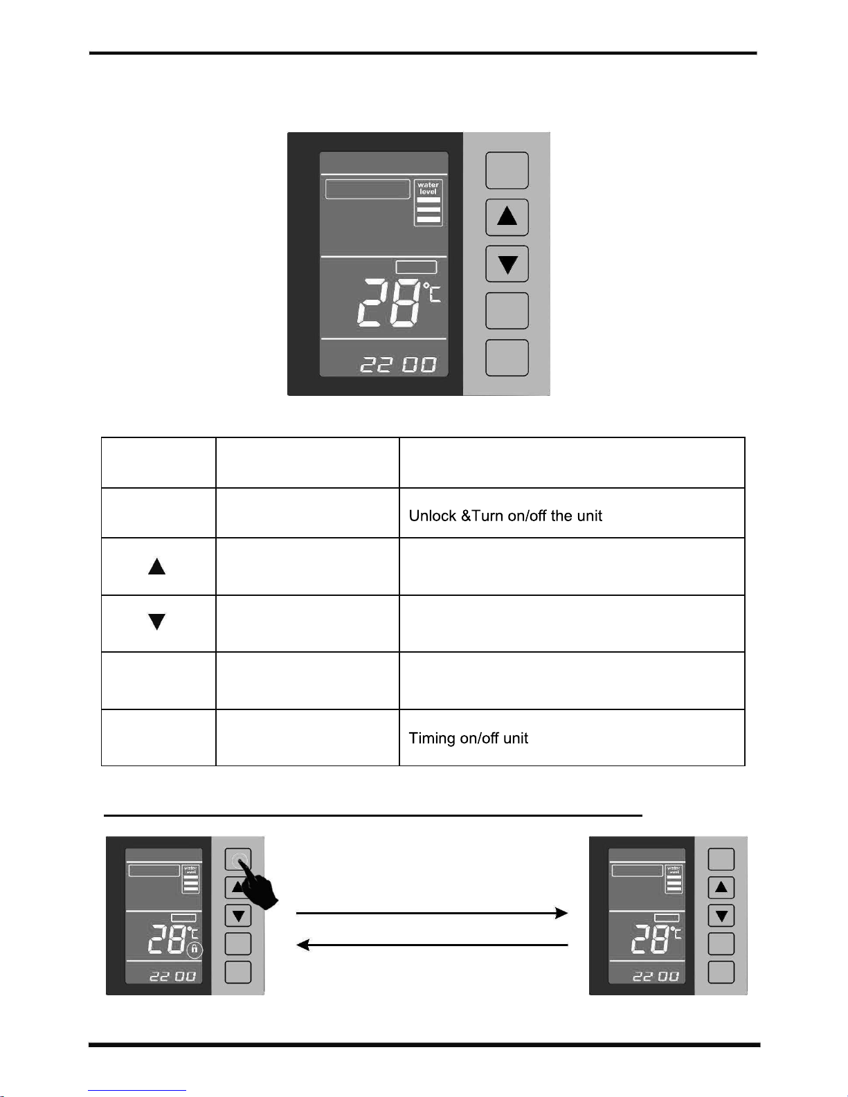
4.Usage a d Opera i nn t o
4.1. Function of the controller
power
water
temperature
setting
:
timer
BUTTON
NAME FUNCTION
power ON/OFF
up Change Mode or increase parameter values
down Manual defrost or increase parameter values
setting Inquiries and setting Query and set parameters
timer Timing
CAUTION: Only after unlocking can perform any operation
power
water
temperature
setting
:
timer
Pressandhold”power”3seconds
When no key operation for about 60
seconds, the keys will be locked
automatically
power
water
temperature
setting
:
timer
13
version 3, release 05th Nov 2017
Page 16
4.USAGE
4.2 Usage of the controller
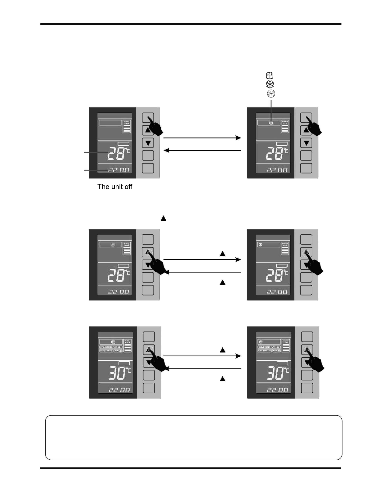
4.2.1 How to start heat pump
The unit can be turnedON/OFFbypressing“power”.
power power
Press”power”
Inlet water
temperature
The current
time
water water
temperature
temperatu re
setting
Press”power”
setting
:
timer
:
timer
The unit on
4.2.2 How to change mode
After unlocking, Press and hold" " 8 seconds. you can change mode.
power
power
Standby
Pressandhold” ”8s
water
water
temperatu re
tempera ture
setting
”8s
settin g
Pressandhold”
:
timer
:
timer
Heating mode
Cooling mode
power
power
Pressandhold” ”8s
Operating
water
water
temperature
temperatu re
status
setting
”8s
setting
Pressandhold”
:
timer
:
timer
Heating mode
Cooling mode
CAUTION: Regardless of unit operation or standby mode can be
changed. After changing the parameters set by the
new model run.
14
When the display ----"heating" mode
When the display ----"cooling" mode
When the display ----”auto” mode
version 3, release 05th Nov 2017
Page 17
4.USAGE
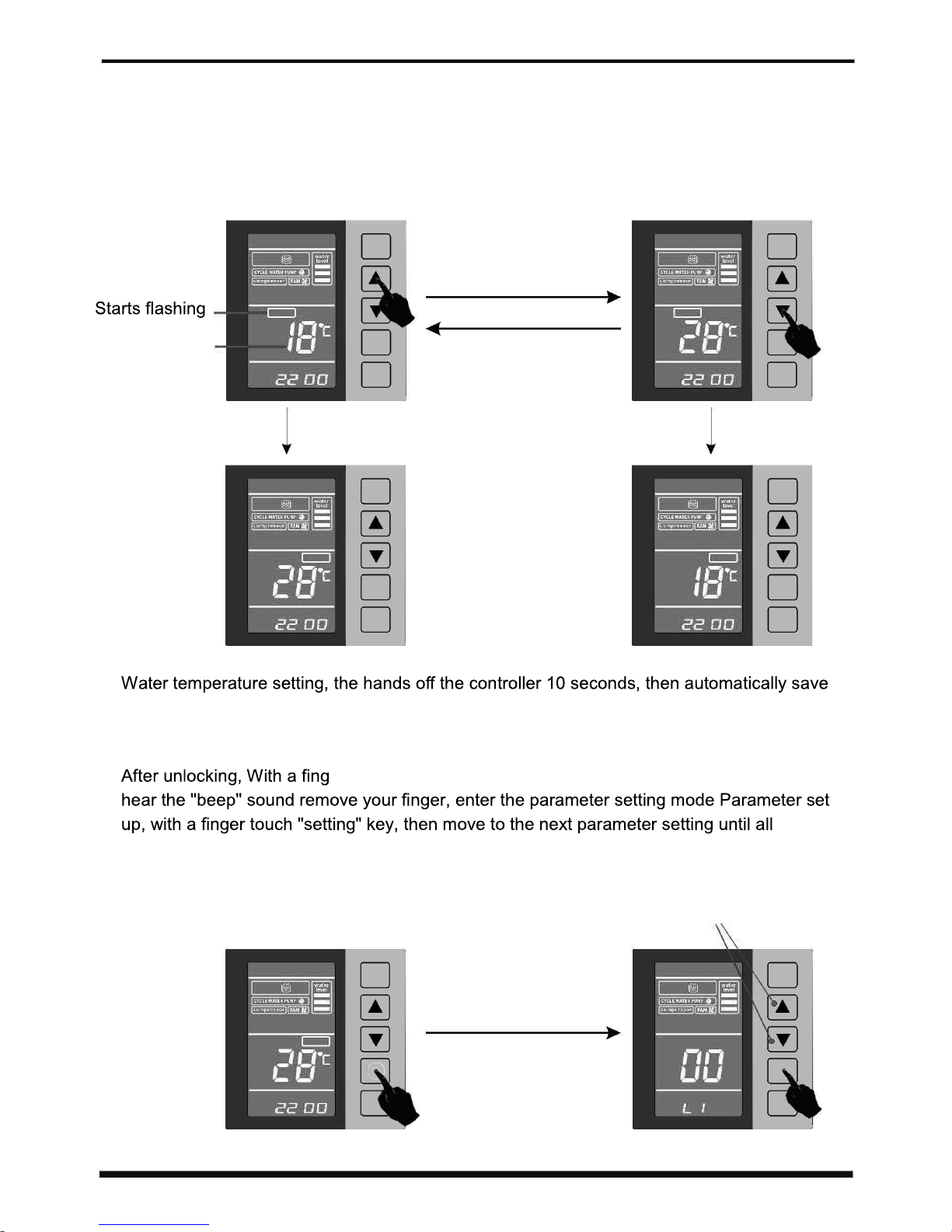
4.2.3 How to set your desired water temperature.
After unlocking, Regardless of unit operation or standby mode can set your desired water
temperature.Press"▲"or "▼"."Set temperature"symbolstarts flashing anddisplay water set
temperature, then fingerpress"▲"or“▼"key, you can change the water temperature setting.
Inlet water
temperature
power
set
temperature
setting
:
timer
power
press"▲"
set
temperature
setting
press “ ▼"
:
timer
After10 seconds After10 seconds
power power
water water
temperatu re
temperatu re
setting
setting
:
timer
:
timer
the settings.
4.2.4 How to change parameter setting.
er touch "setting" key and more than about 3 seconds when you
parameter settings after exit setting mode.
Enter the appropriate parameters,
press"▲"or “▼"keyto change
the parameter settings.
power
power
press and hold
"setting" 3 seconds
water
temperatu re
setting
setting
:
timer
setting
timer
15
version 3, release 05th Nov 2017
Page 18
4.USAGE
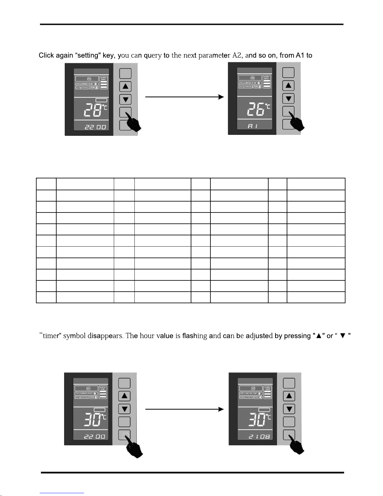
4.2.5 How to check parameter setting & measured values of current status.
After unlocking, Click "setting" , Enter the query parameter mode
Er.
power
power
press "setting"
water
temperatu re
setting
settin g
:
timer
timer
inquire
Hint:
When the system is a dual system, you can continue to query b1 to Er;
three systems can continue to query C1 to Er;
four systems you can continue to query d1 to Er.
Code Meaning Code Meaning Code Meaning Code Meaning
A1 1# Coil temp. b1 2# Coil temp. c1 3# Coil temp.
c1
4# Coil temp.
A2
1# Suction temp. b2 2# Suction temp. c2 3# Suction temp. c2 4# Suction temp.
A3
1# Exhaust temp. b3
2# Exhaust temp.
c3
3# Exhaust temp. c3 4# Exhaust temp.
A4 Ambient temp. b4 Ambient temp. c4 Ambient temp.
c4
Ambient temp.
A5
1# water outlet temp.
b5
2# water outlet temp.
c5 00 c5 00
A6
water inlet temp. b6 water inlet temp. c6 water inlet temp. c6 water inlet temp.
A7
Reserved b7 Reserved c7 Reserved c7 Reserved
A8 1# Comp. current b8 2# Comp. current c8 3# Comp. current c8 4# Comp. current
A9
1#Numerical expansion valve
b9
2#Numerical expansion valve
c9
3#Numerical expansion valve
c9
4#Numerical expansion valve
Er
Fault code
Er
Fault code
Er
Fault code
Er
Fault code
4.2.6 How to set clock.
After unlocking, Press the "timer" key for more than 8 seconds until an audible tone is heard and the
keys.Press the “timer”keyfor minute adjustmentandrepeatas previous. Press“timer”key toexit.
power
power
press and hold "timer"
8 seconds
water water
temperatu re
temperature
setting
settin g
:
timer
:
timer
16
version 3, release 05th Nov 2017
Page 19
4.USAGE
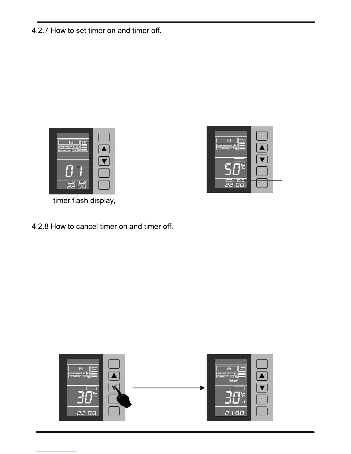
The heat pump consists of two separate timing functions. Timer 01 and 02 are used to set the ON/OFF times of the heat pump
within 24 hour period.
Heat pump ON/OFF timers: 01---ON/OFF timing
02----ON/OFF timing
After unlocking, Press the "timer" key and enter timer 01 ON time as in clock setting section. Press “timer ” key again to set
timer 01 OFF time. Set the OFF time as in clock setting section. Repeat sequence until all timer settings are completed.
If , however ,a timer is not used, set ON and OFF times to 00:00. Timer setting can be randomly selected. For example, Timer
01 ON, Timer 02 OFF.
power
power
timer setting
setting
timer
ON
OFF
:
timer
up with"▲ "or "▼ "
water
temperature
setting
timer
ONOFF
timer
:
timer
ON/OFF
After completing all timer settings, the
controller will display the above.
The cancel the timer feature, pressthe“timer” keyformore than 3 seconds until
an audible tone is heard, then release key, timer is now cancelled.
4.2.9 Manual/forced defrosting.
Although this heat pump features an automatic defrosting function, a manual
defrosting function enables the user to manually defrost the heat pump when
unusual frosting appears.
make sure key-pad is unlocked. Ensure that heat pump unit is in running mode, displaying the
heat symbol.
pressthe“▼" key for more than8secondsuntil anaudible tone is heard, and release key. the
heat pump will be in defrosting mode and the "defrost" symbol will be on display.
water
temperature
power
power
pressandhold“▼"
8 seconds
water
temperature
setting
settin g
:
timer
:
timer
17
version 3, release 05th Nov 2017
Page 20
4.USAGE
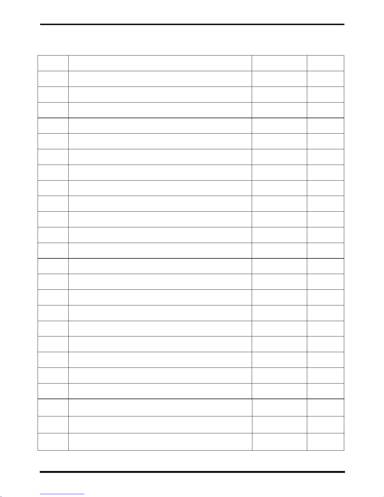
4.3 Parameter table
Channel
L1
///
L2
L3
L4
L5
L6
L7
h1
L9
L8
h2
h3
h4
p1
p2
p3
p4
p5
p6
F1
Parameter name
Adjustment range
Initial value
Pool water temperature
Pool water temperature display deviation value
Compressor starts with the set temperature deviation
Water pump run mode
Set max. temperature
Allow the auxiliary heating of the ambient temp. on
Reserved parameter
Reserved parameter
Compressor current protection settings
Fan for low speed when the ambient temperature set
Minimum defrost cycle ( min)
Defrost start temperature setting
The maximum time set defrost
Exit defrost temperature setting
Electronic expansion valve timing cycle
Superheat
Soft protection exhaust temperature
Defrost electronic expansion valve opening
The min. number of steps to open the expansion valve
Superheat compensation
The number of online setting (Celsius / Fahrenheit Conversion )
300~120 min
0℃─15℃ 0
1℃─15℃ 2
10℃ ─80℃ 34
0℃─35℃ 0
/ /
/ /
0-33A 0
26
20-99min 45
-2
5-20min 10min
1℃─40℃ 20
20s-180s 30s
0
90
6℃─55℃ 50
6℃─30℃ 15
0℃─12℃ 4
1-16 (0-1) 1(0)
F2
20s-120s 60s
Time delay time on line number
F3
Master control unit following
1-16 0
F4
Remote control allows
0-9 0
10℃ ─65℃
0℃─ - 15℃
-8℃ ─15℃
70℃ ─135℃
18
version 3, release 05th Nov 2017
Page 21
4.USAGE
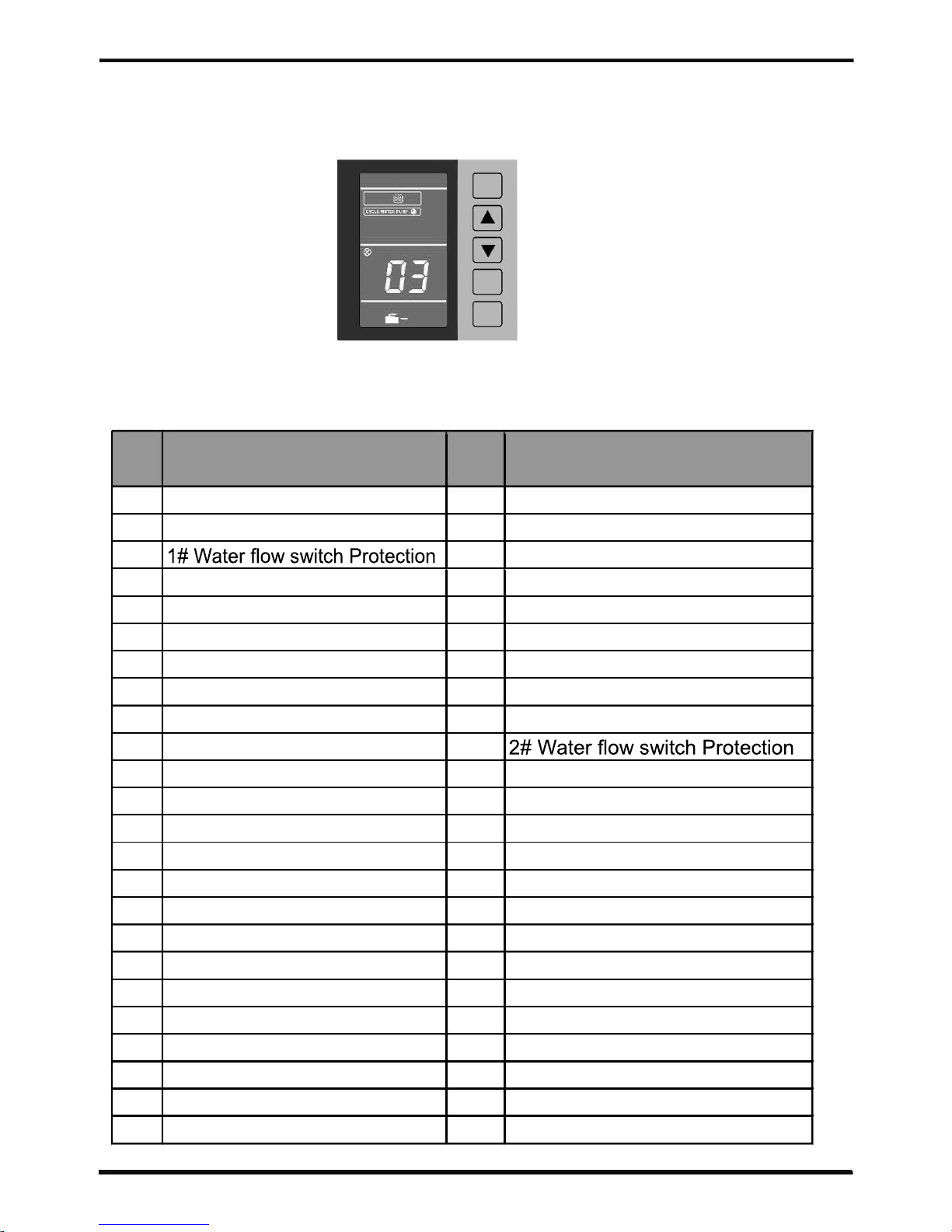
4.4 Mulfunction table
power
error
setting
timer
inquire
Failure Description
Error
Failure Description
code
code
E1 Wrong phase
E30 2# Suction temp. sensor broken
E2 Missing phase
E31 Water pressure sensor broken
E3
E32 Cooling water temperature is too low
E5 1# High pressure protection
E33 Freezing point of failure
E6 1# Low pressure protection
E35 1# compressor overcurrent
E7 2# High pressure protection
E36 2# compressor overcurrent
E8 2# Low pressure protection
E37 1 # thermostat without water
E9 Communication link failure
E38 2 # thermostat without water
E11 Limited time
E39 Cooling water temperature is high
E12 1# High Exhaust temp. protection
E63
E13 2# High Exhaust temp. protection
E65 3# High pressure protection
E15 Water tank sensor broken
E66 3# Low pressure protection
E16 1# coil sensor broken
E67 4# High pressure protection
E17 2# coil sensor broken
E68 4# Low pressure protection
E18 1# Exhaust temp.sensor broken
E72 3# High Exhaust temp. protection
E19 2# Exhaust temp.sensor broken
E73 4# High Exhaus
t temp. protection
E21 Ambient sensor broken
E76 3# coil sensor broken
E22 water return temp.sensor broken
E77 4# coil sensor broken
E23 water inlet temp.sensor broken
E78 3# Exhaust temp.sensor broken
E25 Water level switch broken
E79 4# Exhaust temp.sensor broken
E26 Water inlet temp.is too high
E89 3# Suction temp. sensor broken
E27 1# Outlet water sensor broken
E90 4# Suction temp. sensor broken
E28 2# Outlet water sensor broken
E95 3# compressor overcurrent
E29 1#
Suction temp. sensor broken
E96 4# compressor overcurrent
19
Error
version 3, release 05th Nov 2017
Page 22
5. MAINTENANCE AND INSPECTION
Check the water supply device and the release often. You should avoid the condition of no
it's performance and reliability. You
The area around the unit should be dry, clean and well ventilated. Clean the side heating
exchanger regularly to maintain good heat exchange as conserve energy .
technician .
Check the power supply and cable connection often,.Should the unit begin to operate
a
Discharge all water in the water pump and water system ,so that freezing of the water in the
pump or water system does not occur. You should discharge the water at the bottom of water
pump if the unit will not be used for an extended period of time. You should check the unit
20
version 3, release 05th Nov 2017
Page 23
6.APPENDIX
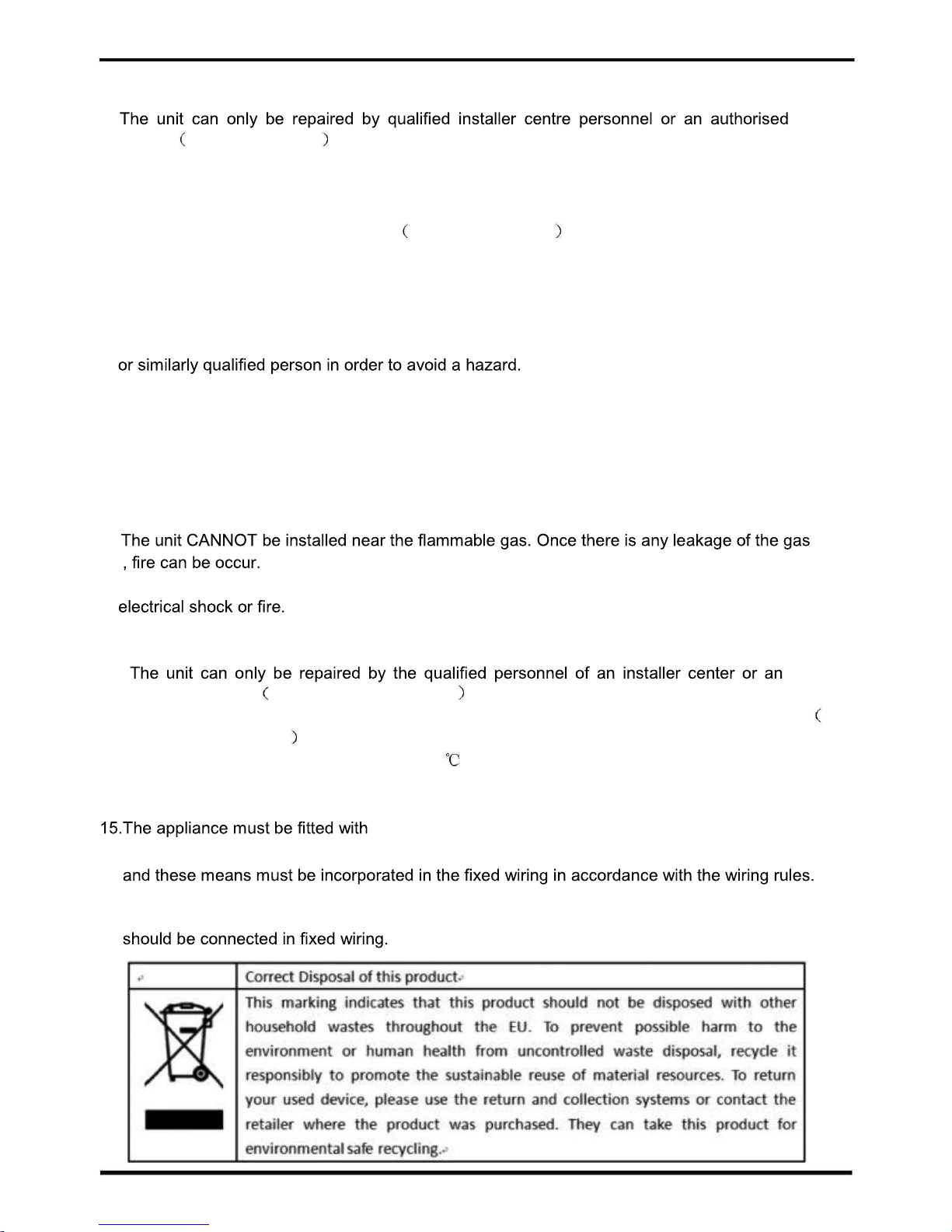
6.1 .Caution & Warning
1.
dealer. for Europe market
2. This appliance can used by children aged from 8 years and above and persons with reduced
physical, sensory or mental capabilities or lack of experience and knowledge if they have
been given supervision or instruction concerning use of the appliance in a safe way and
understand the hazards involved. for Europe market
Children shall not play with the appliance .Cleaning and user maintenance shall not be
made by children without supervision.
3.
Please make sure that the unit and power connection have good earthing, otherwise may
cause electrical shock.
4.
If the supply cord is damaged, it must be replaced by the manufacturer or our service agent
5.
Directive 2002/96/EC (WEEE):
The symbol depicting a crossed-out waste bin that is underneath the appliance indicates
that this product, at the end of its useful life, must be handled separately from domestic
waste, must be taken to a recycling centre for electric and electronic devices or handed
back to the dealer when purchasing an equivalent appliance.
6. Directive 2002/95/EC (RoHs): This product is compliant with directive 2002/95/EC (RoHs)
concerning restrictions for the use of harmful substances in electric and electronic devices.
7.
8. Make sure that there is circuit breaker for the unit, lack of circuit breaker can lead to
9. The heat pump located inside the unit is equipped with an over-load protection system. It does
not allow for the unit to start for at least 3 minutes from a previous stoppage.
10.
authorized dealer. for North America market
11. Installation must be performed in accordance with the NEC/CEC by authorized person only. for
North America market
12. USE SUPPLY WIRES SUITABLE FOR 75 .
13. Caution: Single wall heat exchanger, not suitable for potable water connection.
14.The appliance shall be installed in accordance with national wiring regulations.
means for disconnection from the supply mains having a contact
separation in all poles that provide full disconnection under overvoltage category III conditions,
16.An all-pole disconnection switch having a contact separation of at least 3mm in all poles
17.
21
version 3, release 05th Nov 2017
Page 24
6.APPENDIX
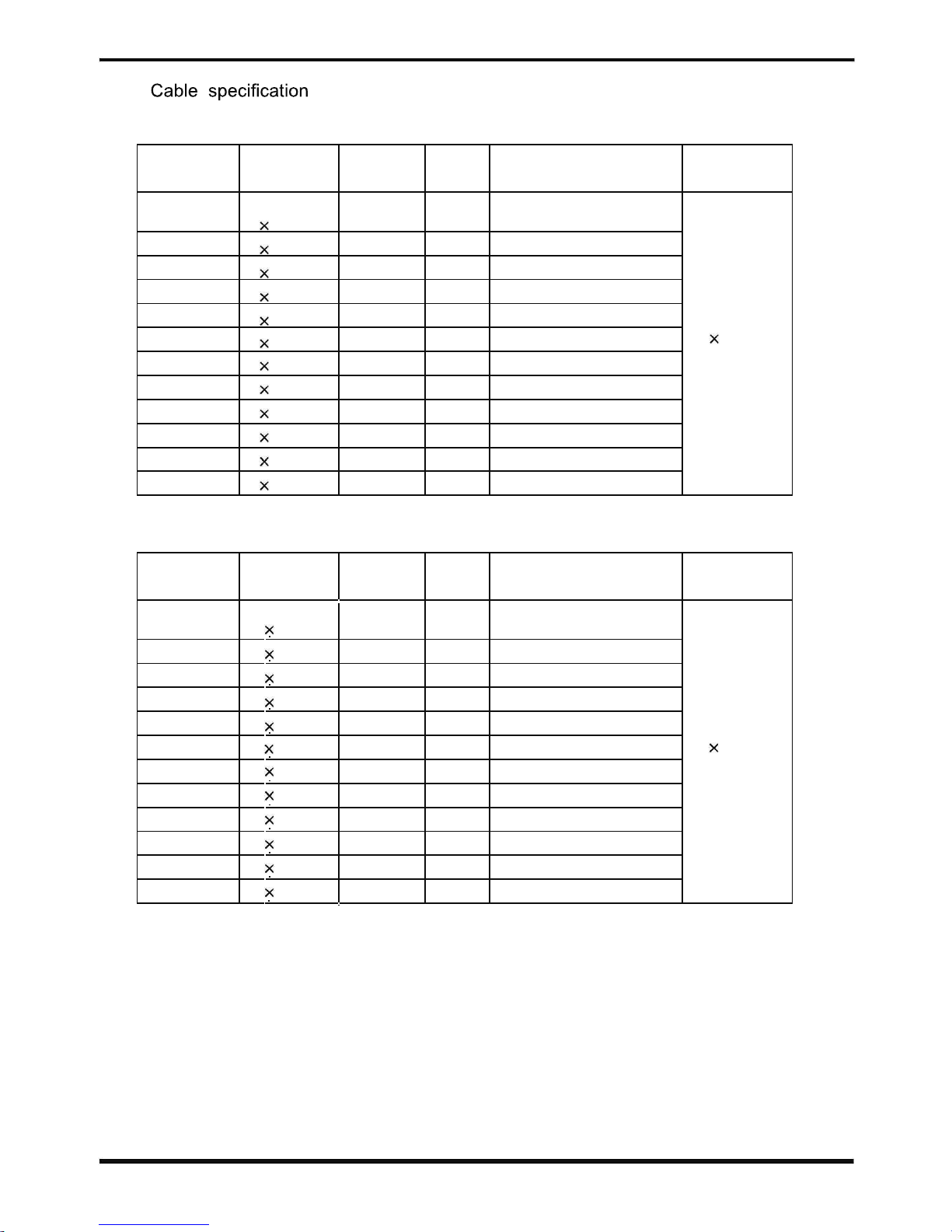
6.2
1. Single phase unit
Nameplate
Phase line Earth line MCB Creepage protector Signal line
maximum
current
No more
30mA less than 0.1 sec
than 10A 2
1.5mm2 1.5mm
2
20A
10~16A 2
2.5mm2 2.5mm
2
32A 30mA less than 0.1 sec
16~25A 2
4mm
2
4mm
2
40A 30mA less than 0.1 sec
25~32A 2
6mm
2
6mm
2
40A 30mA less than 0.1 sec
32~40A 2
10mm2 10mm
2
63A 30mA less than 0.1 sec
n 0.5mm
2
40 ~63A 2
16mm2 16mm
2
80A 30mA less than 0.1 sec
63~75A 2
25mm2 25mm
2
100A 30mA less than 0.1 sec
75~101A 2
25mm2 25mm
2
125A 30mA less than 0.1 sec
101~123A 2
35mm2 35mm
2
160A 30mA less than 0.1 sec
123~148A 2
50mm2 50mm
2
225A 30mA less than 0.1 sec
148~186A 2
70mm2 70mm
2
250A 30mA less than 0.1 sec
186~224A 2
95mm2 95mm
2
280A 30mA less than 0.1 sec
2. Three phase unit
Nameplate
Phase line Earth line MCB Creepage protector Signal line
maximum
current
No more
3
1.5mm
2
30mA less than 0.1 sec
than 10A
1.5mm
2
20A
10~16A 3
2.5mm2 2.5mm
2
32A 30mA less than 0.1 sec
16~25A 3
4mm
2
4mm
2
40A 30mA less than 0.1 sec
25~32A 3
6mm
2
6mm
2
40A 30mA less than 0.1 sec
32~40A 3
10mm2 10mm
2
63A 30mA less than 0.1 sec
n 0.5mm
2
40 ~63A 3
16mm2 16mm
2
80A 30mA less than 0.1 sec
63~75A 3
25mm2 25mm
2
100A 30mA less than 0.1 sec
75~101A 3
25mm2 25mm
2
125A 30mA less than 0.1 sec
101~123A 3
35mm2 35mm
2
160A 30mA less than 0.1 sec
123~148A 3
50mm2 50mm
2
225A 30mA less than 0.1 sec
148~186A 3
70mm2 70mm
2
250A 30mA less than 0.1 sec
186~224A 3
95mm2 95mm
2
280A 30mA less than 0.1 sec
When the unit will be installed at outdoor, please use the cable which can against UV.
22
version 3, release 05th Nov 2017
Page 25
6.APPENDIX
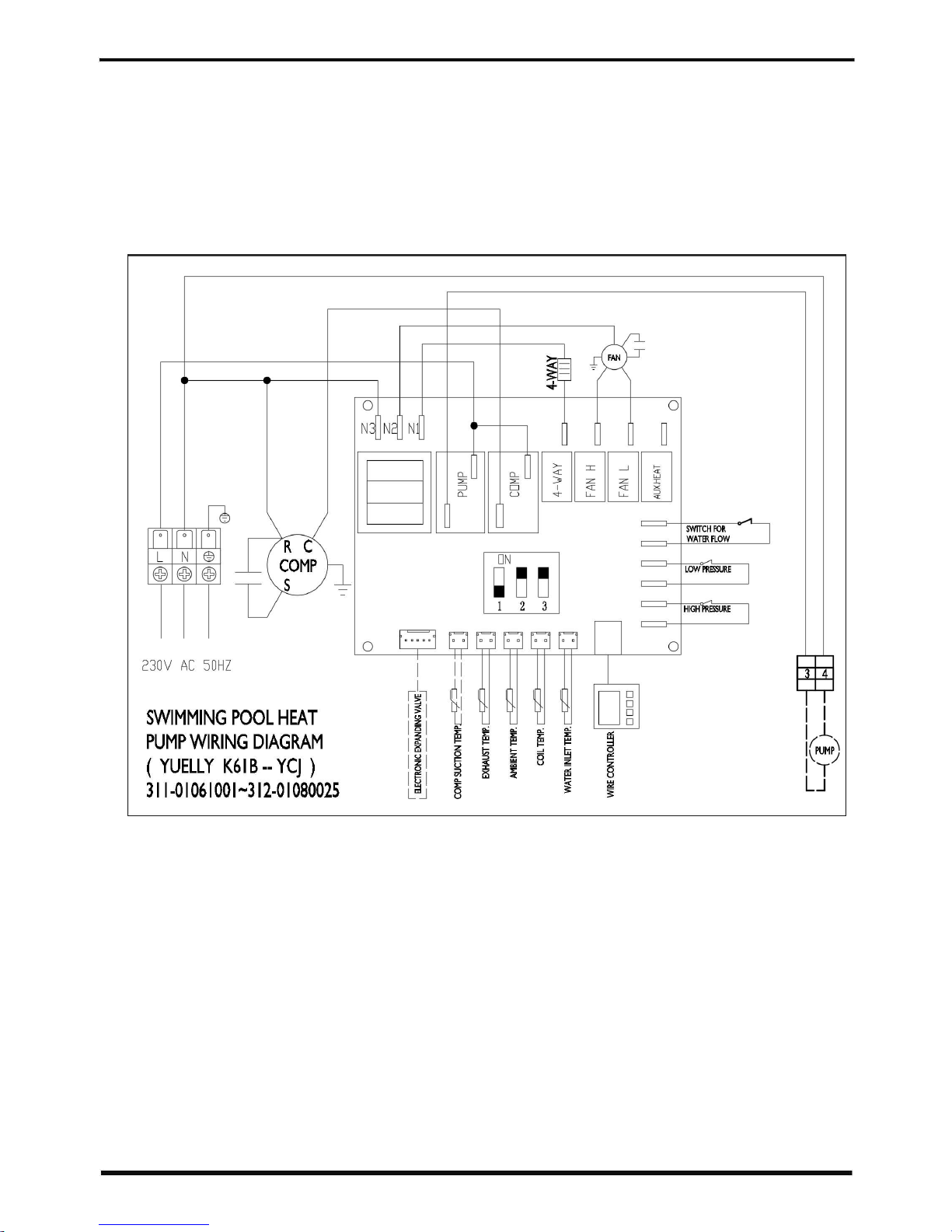
3. Circuit diagram of the unit
23
PHFD-02615
PHFD-02620
version 3, release 05th Nov 2017
Page 26
6.APPENDIX
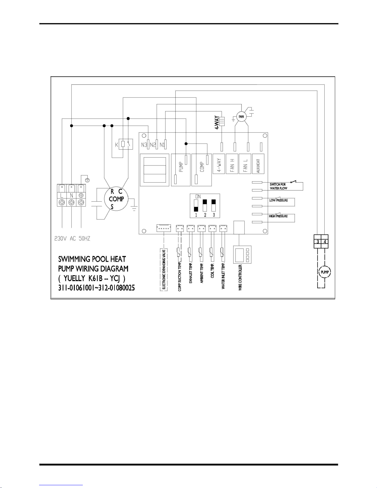
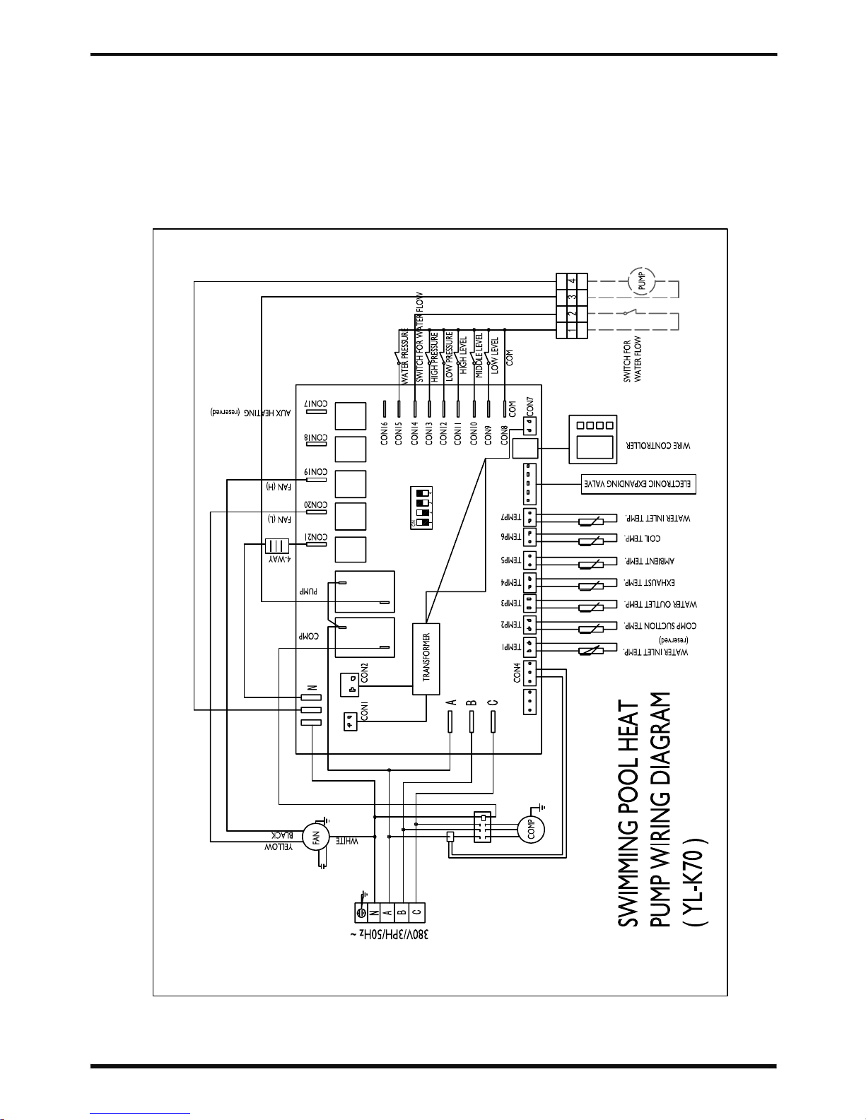
3. Circuit diagram of the unit
24
PHFD-02625
PHFD-02630
version 3, release 05th Nov 2017
Page 27
6.APPENDIX
3. Circuit diagram of the unit
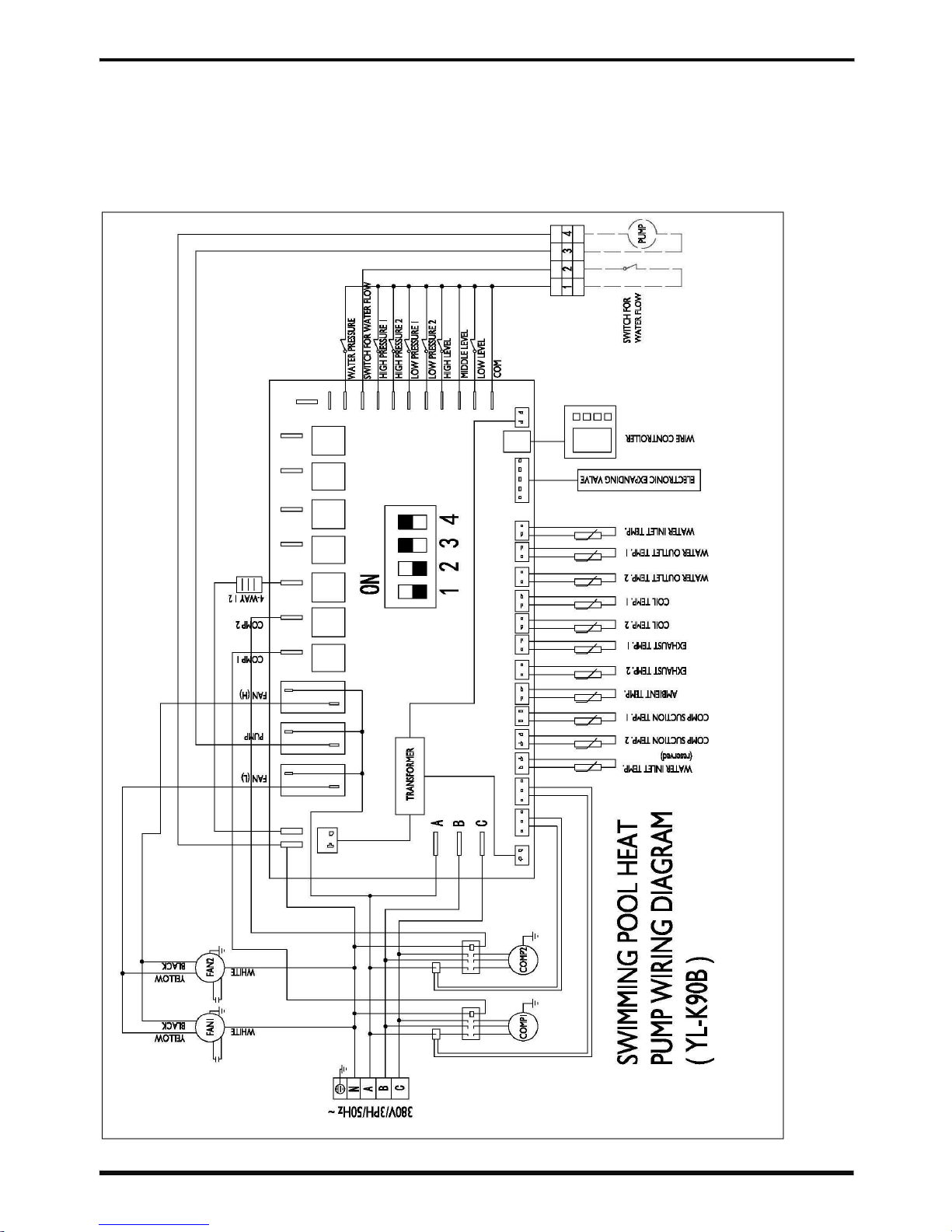
25
PHFD-02640
PHFD-02645
PHFD-02650
PHFD-02660
version 3, release 05th Nov 2017
Page 28
6.APPENDIX
3. Circuit diagram of the unit
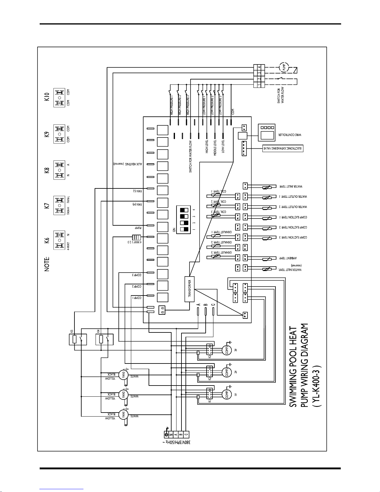
26
PHFD-02710
PHFD-02712
PHFD-02713
PHFD-02714
version 3, release 05th Nov 2017
Page 29
6.APPENDIX
3. Circuit diagram of the unit
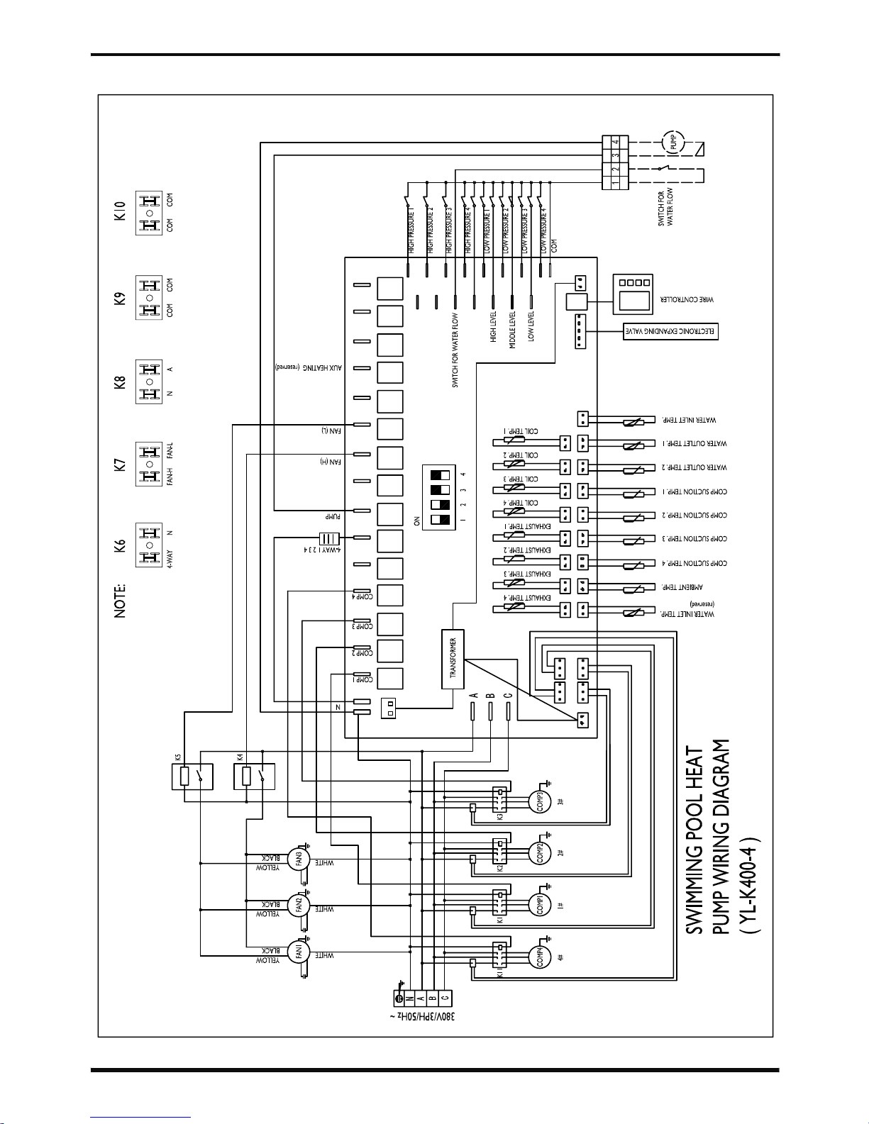
27
PHFD-02715
version 3, release 05th Nov 2017
Page 30
6.APPENDIX
3. Circuit diagram of the unit
28
PHFD-02720
version 3, release 05th Nov 2017
Page 31
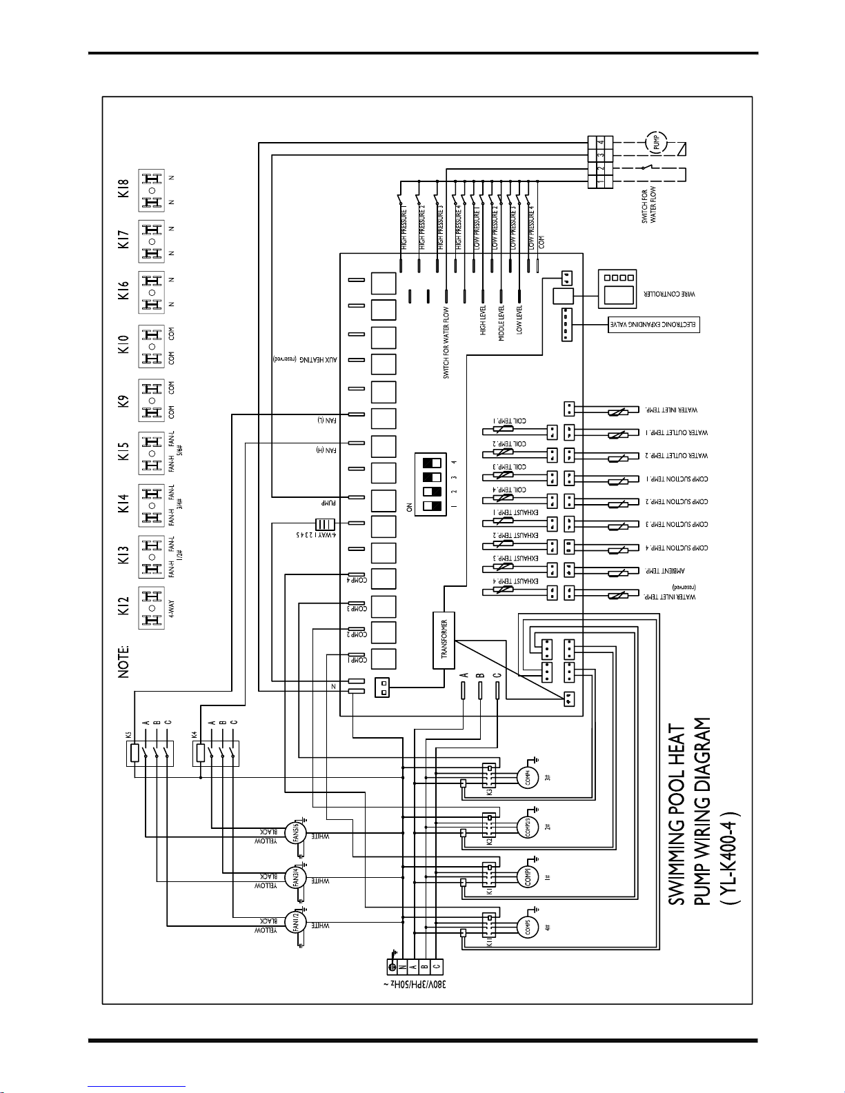
6.APPENDIX
3. Circuit diagram of the unit
29
PHFD-02730
version 3, release 05th Nov 2017
Page 32
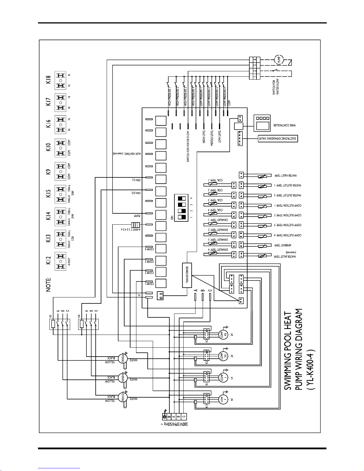
6.APPENDIX
3. Circuit diagram of the unit
30
PHFD-02740
version 3, release 05th Nov 2017
Page 33

version 3, release 05th Nov 2017
 Loading...