

Page 1
R
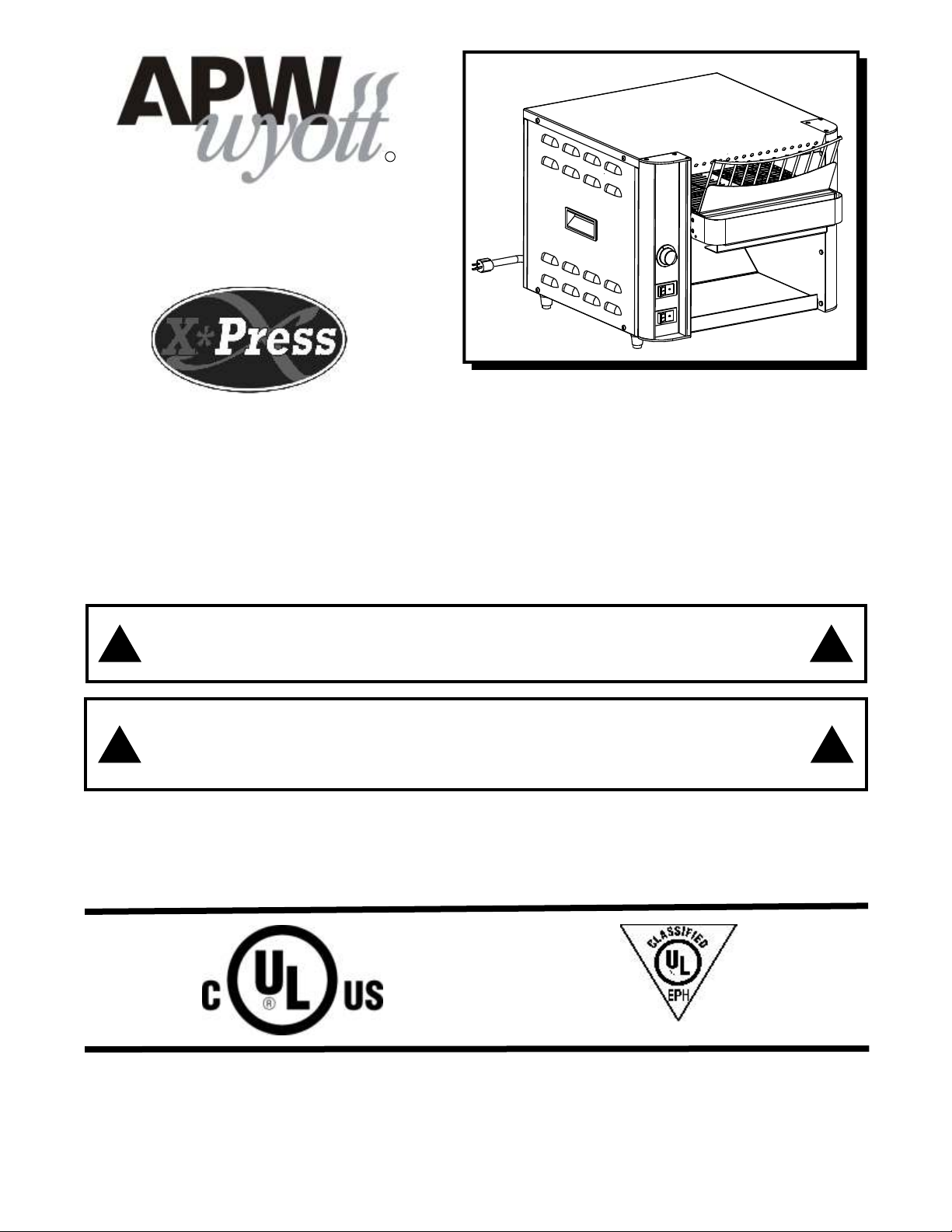
INSTALLATION
AND
OPERATING INSTRUCTIONS
XPRS TOASTER
INTENDED FOR OTHER
THAN HOUSEHOLD USE
Initial heating of appliance may generate smoke or fumes and must be done in a well ventilated area.
Overexposure to smoke or fumes may cause nausea or dizziness.
This equipment has been engineered to provide you with year-round dependable service when used
according to the instructions in this manual and standard commercial kitchen practices.
APPLIANCE MUST BE KEPT CLEAR OF COMBUSTIBLES AT ALL TIMES
FOR YOUR SAFETY: Do not store or use gasoline or other flammable vapors and
liquids in the vicinity of this or any other appliance.
WARNING: Improper installation, adjustment, alteration, service or maintenance can
cause property damage, injury or death. Read the Installation, Operating and
Maintenance Instructions thoroughly before installing or servicing this equipment.
RETAIN THIS MANUAL FOR FUTURE REFERENCE
Model: XPRS
!!
!!
ANSI/NSF4
Phone: +1 (214) 421-7366
Fax: +1 (214) 565-0976
Toll Free: +1 (800) 527-2100
Website: www.apwwyott.com
E-mail: info@apwwyott.com
(800) 733-2203
24 Hour Service Hotline
1
P/N 93100174 9/06
APW WYOTT
729 Third Avenue
Dallas, TX 75226
Page 2

Notes:
IMPORTANT FOR FUTURE REFERENCE
Please complete this information and retain this manual for the life of the equipment. For
Warranty Service and/or Parts, this information is required.
Model Number Serial Number Date Purchased
APW Wyott takes pride in the design and quality of our products. When used as intended and with proper
care and maintenance, you will experience years of reliable operation from this equipment. To ensure best
results, it is important that you read and follow the instructions in this manual carefully.
Installation and start-up should be performed by a qualified installer who thoroughly read, understands and
follows these instruction.
If you have questions concerning the installation, operation, maintenance or service of this product, contact
APW Wyott Foodservice Equipment Company’s “ Technical Service Department”.
2
Page 3

SAFETY PRECAUTIONS
Before installing and operating this equipment be sure everyone involved in its operation are fully trained
and are aware of all precautions. Accidents and problems can result by a failure to follow fundamental rules
and precautions.
The following words and symbols, found in this manual, alert you to hazards to the operator, service
personnel or the equipment. The words are defined as follows:
DANGER: This symbol warns of imminent hazard which will result in serious injury or death.
!
WARNING: This symbol refers to a potential hazard or unsafe practice, which could result in
!
serious injury or death.
CAUTION: This symbol refers to a potential hazard or unsafe practice, which may result in minor or
moderate injury or product or property damage.
!
NOTICE: This symbol refers to information that needs special attention or must be fully understood
even though not dangerous.
!
!
!
!
!
TABLE OF CONTENTS
SECTION ITEM PAGE
1 Important Safety Instructions 3
2 General Information 5
3 Installation Instructions 5
4 Operation Instructions 5
5 Cleaning Instructions 6
6 Specifications 6
7 Troubleshooting 7
8 Parts List with Exploded View 8
9 Wiring Diagram 10
10 Warranty 11
1. IMPORTANT SAFETY INSTRUCTIONS
IMPORTANT: Read the following important safety instructions to avoid personal injury or
!
!
!
death, and to avoid damage to the equipment or property.
WARNING: APW Wyott toasters are designed, built, and sold for commercial use. If positioned
where the general public can usethem, make sure that all cautions, warnings, and operating
instructions are clearly posted near each unit to insureproper operation, reduce the chance of
personal injury and/or equipment damage.
WARNING: Plug unit into a properly grounded electrical outlet of the correct voltage, size and plug
configuration. If the plug and receptacle do not match, contact a qualified electrician to determine
the proper voltage and size and install the proper electrical outlet.
3
!
!
!
Page 4

WARNING: To avoid any injury, turn the power switch off at the fuse disconnect switch/circuit
breaker or unplug the unit from the power source and allow to cool completely before performing
!
any maintenance or cleaning.
WARNING: To avoid electrical shock, always unplug the unit before performing cleaning or
maintenance.
!
WARNING: For safe and proper operation, the unit must be located a reasonable distance from
combustible walls and materials. If safe distances are not maintained, discoloration or combustion
!
could occur.
WARNING: To avoid electrical shock or personal injury, do not steam clean or use excessive water
on the unit.
!
WARNING: If service is required on this unit, contact your authorized APW Wyott Service Agent, or
contact the APW Wyott Service Department directly at (214) 421-7366 or (800) 527-2100; fax (214)
!
565-0976.
WARNING: This product has no “user” serviceable parts. To avoid damage to the unit or injury to
personnel, use only Authorized APW Wyott Service Agents and genuine APW Wyott Parts when
!
service is required..
WARNING: Genuine APW Wyott Replacement Parts are specified to operate safely in the
environments in which they are used. Some aftermarket or generic replacement parts do not have
the characteristics that will allow them to operate safely in APW Wyott equipment. It is essential to
!
use APW Wyott Replacement Parts when repairing APW Wyott equipment. Failure to use APW
Wyott Replacement Parts may subject operators of the equipment to hazardous electrical voltage,
resulting in electrical shock or burn.
!
!
!
!
!
!
!
CAUTION: Some exterior surfaces on the unit will get hot. Use caution when touching these areas
!
to avoid injury.
CAUTION: Locate the unit at the proper counter height, in an area that is convenient for use. The
location should be level to prevent the unit or it’s contents s
!
!
4
Page 5

2. GENERAL INFORMATION
1. Overall Dimensions w/Wire Feeder - 13.610”H (34.5cm) x 15.192”W (38.6cm) x 17.982”D (45.7cm)
2. Product Opening - 1.50”H (3.8cm) x 10.50”W (26.7cm)
3. Electrical Requirements (Single phase):
A. 120 Volt, 1800 Watt, 15 Amp.
B. 208 Volt, 1800 Watt, 8.5 Amp.
C. 230/240 Volt, 1800 Watt, 7.8 Amp.
D. Cordset configuration
1. Each toaster equipped with three wire grounded cordset and standard three-prong plug.
2. In the U.S.: 120V uses NEMA 5-15P. 208, 230/240V uses NEMA 6-20P .
3. In Canada: 120V uses NEMA 5-20P.
4. Net/Shipping Weight – 28 lb.(12.7kg) / 33 lb.(14.97kg)
3. INSTALLATION INSTRUCTIONS
I. Check Contents - refer to Figure 1, account for the following parts:
A. Wire Feeder - inside Reflector Tray
B. Reflector Tray - shipped in place
C. Toast Drawer - shipped in place
D. Instruction Manual - shipped loose
2. Position Wire Feeder
A. Pull out Reflector Tray
B. Rotate Wire Feeder
C. Slide Reflector Tray back
D. WARNING: Operating toaster without Reflector Tray reduces toasting capabilities.
3. Toaster Placement
A. Locate toaster near a grounded receptacle of the proper configuration (see below). Plug
the cordset directly into receptacle (DO NOT USE AN EXTENSION CORD).
1. In the U.S.: 120V uses NEMA 5-15R. 208, 230/240V uses NEMA 6-20R.
2. In Canada: 120V uses NEMA 5-20R.
B. Place toaster on flat surface providing following minimum clearances:
1. Base = one inch (provided with legs installed).
2. Side and back walls = two inches
3. Overhead = Enough space to allow adequate heat displacement.
C. Position toaster where customers will not contact any surface labeled “CAUTION HOT”.
4. OPERATION INSTRUCTIONS
1. Preparation
A. Clean toaster thoroughly before first use (See cleaning instructions).
B. Controls Familiarity
1. Main Power Switch (located on very bottom of control panel): There are two rocker switches.
The bottom switch powers the unit “ON”. It also turns on the bottom element. The top switch is
a standby switch (upper heat switch) that runs the top element. When the standby switch is in
the “ON” position the unit is at full power. When the standby switch is in the “OFF” position the
unit is running at 50%.
a) Full Power: Flip both rocker switches to the right.
b) Power Off: Flip both rocker switches to the left.
2. Conveyor Speed Control: Set knob to the three (3) position for warm-up.
C. Warm-up time: Allow five (5) minutes.
2. Normal Use
A. Loading Product
1. Place product on Wire Feeder. The conveyor will automatically draw product through the
toaster at a speed determined by conveyor speed control.
C
Figure 1
A
B
5
Page 6

B. Toasting Darkness: determined by conveyor speed.
1. Darkest toasting - set conveyor speed control to far left setting.
2. Lightest toasting - set conveyor speed control to far right setting.
3. Other factors affecting toasting darkness.
4. For best results, use day old bread stored room temperature.
1. Daily Cleaning
A. With toaster off and cool, turn toaster on and set conveyor speed to four.
B. Using a plastic abrasive pad, wipe the conveyor belt in a back and forth motion (side-to-
side) motion to remove baked-on product. Wipe the conveyor belt in the same manner
with a hot, damp cloth.
C. Turn off toaster.
D. Slide the reflector/crumb tray out of toaster by pulling forward. Dispose of crumbs and
wash tray in hot, soapy water. Dry tray and place back in toaster.
E. Remove toast drawer from toaster by sliding out and lifting up. Dispose of crumbs and
wash drawer in hot, soapy water. Wipe crumbs from inside the toaster with a hot, damp
cloth. Dry drawer and place back in toaster.
F. Wipe the exterior surfaces of the toaster with a hot, damp cloth.
a) Product moistness - moister product requires slower speeds
b) Sugar content in product - product with more sugar requires slower speeds
c) Product Temperature - cooler product requires slower speeds
5. CLEANING INSTRUCTIONS
Page 7

7. TROUBLESHOOTING
1. Always ask and check the following:
A. Is the unit connected to a live power source?
B. Check the circuit breaker.
C. Is power switch on?
D. Is the unit operating on proper voltage?
2. If problems exist after checking the above, check the chart below.
3. If any service is needed (italicized items), call an APW Wyott authorized service agency.All service
should be performed by an APW Wyott authorized service agency.
PROBLEM CAUSE SOLUTION
Won’t toast... a. Toaster cold. a. Allow five (5) minutes for warm up.
b. Wrong power switch position. b. Position power switch to full power.
c. Wrong conveyor speed setting. c. Reduce conveyor speed.
Toasts unevenly... d. Only part of product surface is d. Reduce conveyor speed.
toasted.
e. Product located to far to side of e. Place product on conveyor between
Conveyor. End links.
Product sticks to f. Butter or butter substitute used f. Discontinue use of butter or butter
conveyor or slide.. on product. substitute.
g. Conveyor surface has baked-on g. Follow daily cleaning methods to
oil residue. remove & prevent residue.
h. Very moist or doughy product. h. Use different source or day old product.
i. Product not defrosted or thawed. i. Defrost/thaw product.
No power... j. No power to receptacle. j. Check circuit breaker.
k. Toaster unplugged. k. Plug in toaster.
l. Loose connections. l. Check connections.
m. Power switch. m. Check that switch is on & operational.
Won’t heat... n. Loose connections. n. Check connections.
o. Faulty power switch. o. Replace power switch.
p. Burnt out element. p. Replace element.
Lighter toast under q. Speed control setting. q. Reduce speed control setting.
peak loads... r. Very moist product. r. Use different source or day old
product.
s. Product too cold. s. Allow product to warm to room
temperature.
t. Toaster cavity temperature being t. Add 1” or more spacing between
quenched. product.
Conveyor won’t u. No power. u. Check circuit breaker.
Move... v. Conveyor links are binding. v. Check conveyor for bent links.
w. Loose or bad connection between w. Check for loose or bad connection.
speed control and conveyor motor.
x. Conveyor motor burnt out. x. Replace conveyor motor.
y. Speed control burnt out. Y. Replace speed control.
7
Page 8

14
2
43
4
43
12
41
1
21
4
20
2
22
6
1
10
13
1
29
30
1
40
1
32
4
39
19
2
31
4
36
1
1
33
1
50
2
48
1
1
5
24
2
23
1
49
4
45
4
9
4
1
1
37
34
1
44
11
38
10
6
42
1
25
2
22
10
8
2
46
2
44
6
2
1
11
1
16
1
17
1
15
1
35
1
47
12
7
2
3
1
8
2
12
2
2
26
27
1
10
1
2
1
14
2
18
1
Page 9

PARTS LIST
ITEM PART NUMBER DESCRIPTION QUANTITY
1
2
3
4
5
6
7
8
9
10
11
12
13
14
15
16
17
18
19
20
21
22
23
24
25
26
27
28
29
30
31
32
33
34
35
36
37
38
39
40
41
42
43
44
45
46
47
48
49
50
93100158
93100160
93100162
93100150
93100061
93100060
93000067
93000070
83267
93100058
93100101
70444800
93100069
81600095
93100063
83221
83222
88705
38129
93100033
54087
54088
54089
93100047
89061
83248
83821
38130
38125
38122
89184
85286
85248
85152
85149
85144
89076
89030
83209
85287
83956
83261
93100064
89073
82902
89111
85638
85640
PS0018
89039
81600087
89063
83868
94000114
34236
34236
89054
RIVET ASSY, XPRS INNER CORE
XPRS-CONTROL PANEL EXTRUSION
XPRS-RIGHT SIDE EXTRUSION
XPRS-TOP COVER LEFT
XPRS-PANEL, LEFT OUTER
XPRS-PANEL, RIGHT OUTER
END CAP, F/L & B/R
END CAP, B/L & F/R
LEG 1" PLASTIC W/CHROME
ASSY, XPRS FEEDER
WELD ASSY, XPRS-CONTROL PANEL
SWITCH, ROCKER ON-OFF
XPRS-BACK COVER
HANDLE, POCKET PULL SERIES
XPRS-PLATE, CONTROL PANEL
RHEOSTAT, MOTOR CONTROL 120V
RHEOSTAT, MOTOR CONTROL 208, 230/240V
KNOB 039-266 8A BLACK
DRAWER TOAST
ASSY, ELEMENT HOLDER
ELEMENT 120V 832W
ELEMENT 208V
ELEMENT 230/240V
XPRS-ELEMENT END CAP
NUT, HEX 10-24
BEARING, SHAFT
BRACKET, BEARING
ASSY, CLIP BEARING
BEARING FLANGED POLYMER
W'ASSY IDLER SHAFT
BUSHING, .875 HEYCO 2126
FAN MOTOR COOLING 120V
FAN MOTOR COOLING 208, 230/240V
MOTOR AT10 115V 60HZ
MOTOR AT10 208/240V 60HZ
MOTOR AT10 230V 60HZ
WASHER, LOCK 1/4 INTERNAL
SCREW, 10-32X3/4
SPROCKET, 23 TOOTH 1/4 PITCH 5/16 BORE
FAN GUARD
DRIVE SHAFT ASSY AT-10 SEGMENTED BELT
SPROCKET, 12 TOOTH 1/4 PITCH 3/8 BORE
HEX MACHINE SCREW, #6-32 X 1/4
SCREW, #8 X 1/2 HEX TAPIT SHT MTL TYPE AB
CHAIN, 1/4" DRIVE 67 PITCH
BUSHING, STRAIN RELIEF SR-7W-2
CORDSET 14/3 600V 5-20P (120V)
CORDSET 14/3 600V 5-20P (230&240V)
BELT, WIRE 27x.05 3 SEG.
SCREW, 8-32X5/16 PH PAN SS
SCREW, 8-32 x 3/8, PHILLIPS, PAN HEAD
NUT, HEX 8-32
SPACER, CONVEYOR SHAFT
SCREW, COUNTERSINK, 6-32X5/16,Z,BLK
TERMINAL BLOCK END MTG
TERMINAL BLOCK END MTG
NUT, KEPS 6-32
1
1
1
1
1
1
2
2
4
1
1
2
1
2
1
1
1
1
1
2
2
2
2
4
10
2
2
2
2
1
1
1
1
1
1
1
4
4
1
1
1
1
11
10
1
1
1
1
1
12
6
4
2
12
1
4
2
9
Page 10

9. WIRING DIAGRAM9. WIRING DIAGRAM
CORD SET
L1
1
L2
2
7
GND
STANDBY SWITCH
8
DRIVE MOTOR
TOP ELEMENT
11
COOLING FAN
10
BOTTOM ELEMENT
TERMINAL BLOCK
9
ON/OFF SWITCH
6
4
5
RHEOSTAT
3
BLUE
BLACK
Page 11

11
Page 12

Phone: +1 (214) 421-7366
Fax: +1 (214) 565-0976
Toll Free: +1 (800) 527-2100
Website: www.apwwyott.com
E-mail: info@apwwyott.com
12
APW WYOTT
729 Third Avenue
Dallas, TX 75226
 Loading...