

Page 1
INSTALLATION
AND
OPERATING
R
INSTRUCTIONS
EASY-FILL HOT FOOD WARMER
Models:
SM50EZ, SHFWEZ-12D, SHFWEZ-1,
SHFWEZ-2D, -3D, -4D, -5D, -6D
INTENDED FOR OTHER THAN HOUSEHOLD USE
RETAIN THIS MANUAL FOR FUTURE REFERENCE
UNIT MUST BE KEPT CLEAR OF COMBUSTIBLES AT ALL TIMES
WARNING: Improper installation, adjustment, alteration, service or maintenance can
cause property damage, injury or death. Read the Installation, Operating and
Maintenance Instructions thoroughly before installing or servicing this equipment.
Initial heating of unit may generate smoke or fumes and must be done in a well ventilated area.
Overexposure to smoke or fumes may cause nausea or dizziness.
This equipment has been engineered to provide you with year-round dependable service when used
according to the instructions in this manual and standard commercial kitchen practices.
P/N 70103009 3/06
Phone: +1
Fax: +1 (214) 565-0976
Toll Free: +1 (800) 527-2100
Website: www.apwwyott.com
E-mail: info@apwwyott.com
(214) 421-7366
APW WYOTT
729 Third Avenue
Dallas, TX 75226
!!
1
Page 2
TABLE OF CONTENTS
General Installation
Specifications:
SM50EZ
SHFWEZ-12D
SHFWEZ-1D
SHFWEZ-1D w/Shut-Off Valve
SHFWEZ-2, -3, -4, -5, -6
SHFWEZ-2D, -3D, -4D, -5D, -6D w/Shut-Off Valve
Warranty
2
A SM50EZ
B SM50EZ-12D 5
C SHFWEZ-1D 6
D SHFWEZ-2, -3, -4, -5, -6 7
Parts List & Exploded View
Wiring Diagram 9
Parts List & Exploded View
Wiring Diagram 11
Parts List & Exploded View
Wiring Diagram 13
Parts List & Exploded View 14
Parts List & Exploded View
Parts List & Exploded View 18
Wiring Diagram 20
4
8
10
12
16
22
GENERAL INSTALLATION
1. Always clean equipment thoroughly before use. (See general cleaning instructions.)
2. Check rating label for your model designation & electrical rating.
3. For best results, use stainless steel counter tops.
4. All dimensions in parenthesis in centimeters unless noted.
INSTALLATION INSTRUCTIONS FOR EZ WELL SUPPLY LINE
1. Install PIN 54508, brass fitting in each end of the solenoid using Teflon tape (not supplied).
2. Wrap the threads of the fitting as shown in the figure NO.1.
3. Remove the nut from the brass fitting and the sleeve from the inside of the fitting.
4. Place the sleeve and the nut, nut first, over the W copper tubing, PIN 54578, supplied with the
equipment.
5. Install the line into the solenoid and tighten the nut finger tight.
6. Using a wrench, tighten the nut far enough to crush the sleeve and attach the line.
NOTE:
7. Install the 3/8 x 1/4 adapter to the 3/8 stainless steel tube fitting using Teflon tape as shown in
figure NO.2.
8. Using the other end of the copper tube, install the line, nut, and sleeve to theadapter.
9. Tighten using the sameprocedure as before.
10. Turn on water supplyand look for leaks. If any leaks are found, tighten the nuts until leak is stopped.
NOTE:
To fill, turn one control to the first position and allow all wells to fill completely. After wells are full, set
controls to desired settings.
INSTALLATIONMUSTBE DONE BYAUTHORIZEDPLUMBER.
Do not over tighten nut. Just enough pressure is required to stop water leaks.
With EZ-fill multi-well units, turning on any of the controls will start water to fill all of the wells.
2
Page 3
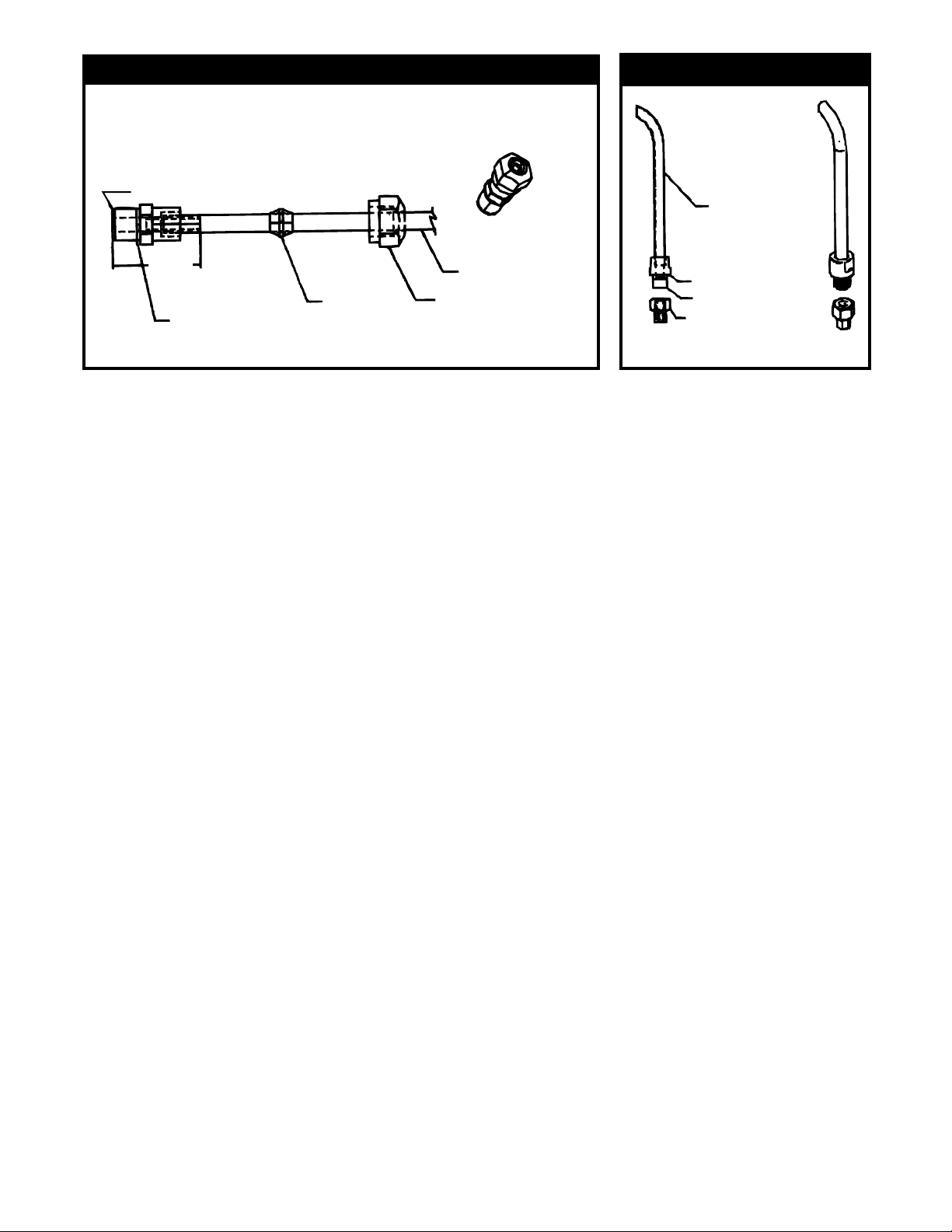
FIGURE #1
Part Description: Brass Connector Male 1/8” NPT x 1/8” Tube
1/8 NPT
FIGURE #2
Inlet Tube
1.125
Sleeve
Teflon Tape APW
#89117, as Required
1/4” Copper Tube
Fitting Nut
Coupling
Teflon Tape
3/8” Female to
1/4” Tube Adaptor
GENERAL OPERATION INSTRUCTIONS
1 . All food service equipment should be operated by trained personnel.
2. Do not allow your customers to come in contact with any surface labeled "CAUTION HOT."
3. Do not cook, warm or hold food directly in liner pans (well pans). Always use steam table pans /
insets, etc. Steam table pan depth shouldnot exceed 6".
4. Never hold food below 150°F (66°C).
Wet set-up and operation procedures (Units with drains)
1. Turn thermostat control to "10" setting or if equipped with infinite controls to "7" or "HI". Preheat for
approximately 30 minutes. Pans will fill, to correct level,with water to white probe. . 2. Place covered
inset with preheated product into well. 3. Readjust control after another 30 minutes of operation to
the "6" setting depending on the amount and/or thickness of product. 4. Keep inset / steamtable
pan(s) covered to maintain ideal servingtemperature. 5. Water is automatically kept at correct level.
NOTE: Turning on any controlwill activate autofill.
GENERAL CLEANING INSTRUCTIONS
1. NEVER clean any electrical unit by immersing it in water. Turn off before surface cleaning.
2. Always clean equipment thoroughly before first use. Clean unit daily. Except where noted on charts:
Use warm, soapy water. Mild cleansers & PLASTIC scouring pads may be used to remove bakedon food & water scale.
3. Turn off electrical units before cleaning or servicing. All service should be performed by an APW
authorized agency.
GENERAL TROUBLESHOOTING
Always Ask & Check:
1. Is the unit connected to a live power source?
2. Check the circuit breaker.
3. Is power switch on & pilot light glowing?
4. Check rating label.Are you operating unit on proper voltage?
If the above checks out, and you still have problems, call an APW authorized service agency.
3
Page 4
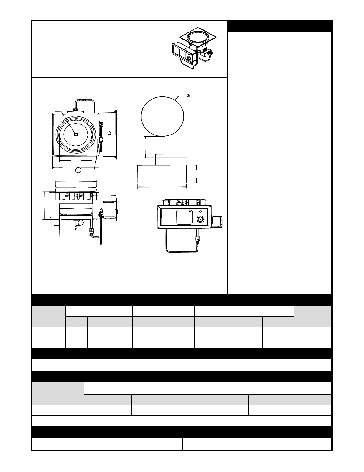
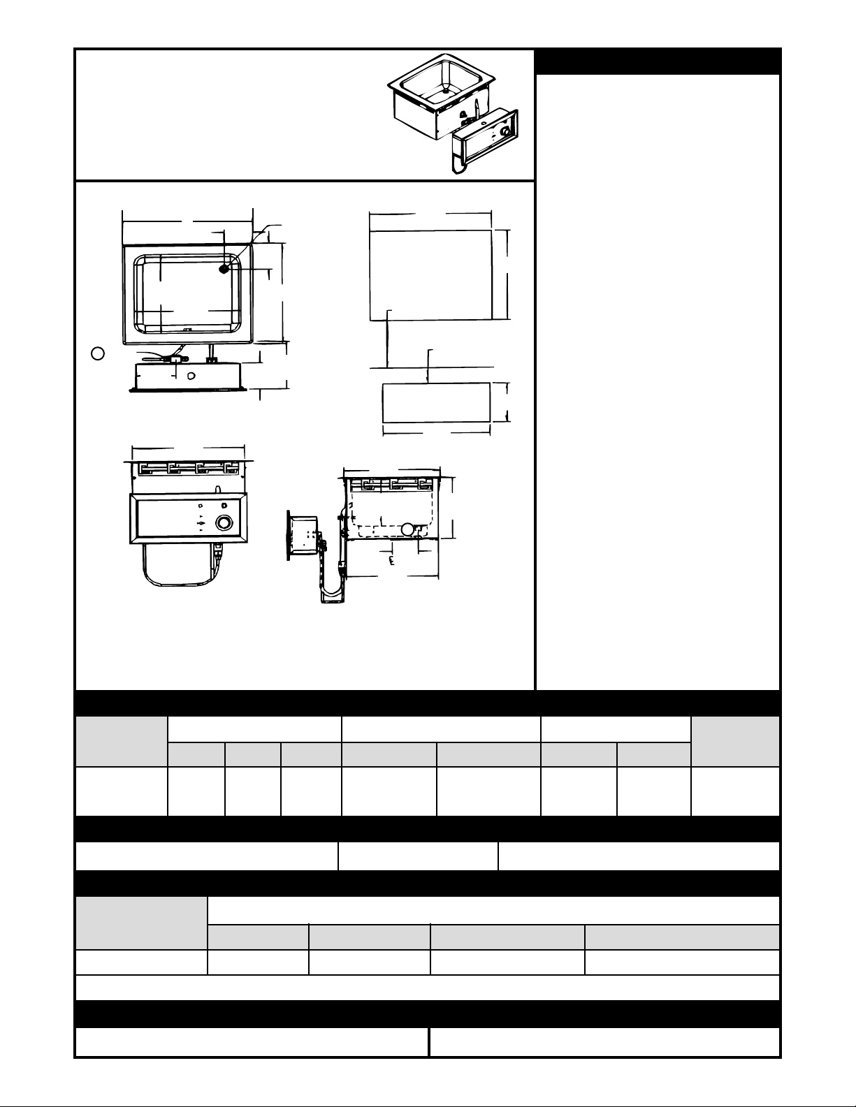
INSTALLATION
APW EZFILL HOT FOOD WELLS
Part Numbers Beginning with WHFW
D
Drain
6.0 (15.2) Minimum
From Counter Edge
E
7.78
(198)
12.02
(305)
7.55
(192)
4.19
(10.6)
10.69
(27.1)
C
1
B
8.12
(20.6)
Water
Inlet
A
610
(155)
2
1. Water fill is 3/8 (1.0) tubing connection on left back of left controls.
2. Main drain is ¾ female NPT.
Soup Well
Cut-out
2.0 (5.1) Minimum
From Counter Top
F
G
Control Cut-Out
1. Follow general installation
instructions on page 3.
2. Make applicable Cut-Out per above
table. Unit is designed for
Note:
installationin stainless steel tops.
Optional wood mounting kit available.
3. Apply putty tape to the underside
perimeter of the well rimouteredge.
4. Apply a 1/4" (.6) bead of silicone
sealant adjacent to the putty tape on
the well flange.
5. Drop well into opening from the top
and push down until entire
parameter of rim is flush with the
counter surface.
6. From below the counter surface
insert an 8" to10"(20to 25 cm) flat tip
screwdriver into the locking ring tab
slots and twist in a clockwise motion
to lock well in place.
7. Trim excess putty and sealant from
around well rim.
8. Mount control to front panel using
hardware. Maintain 4" (10.2)
clearance between well and front
panel.
9. Check nameplate for proper voltage.
Connect power.
10. Connect overflow tube on hot food
well to suitable tubing to handle
212°F water.Run to open drain.
Electrically connect units to
Note:
comply with local and NECcodes.
GENERAL SPECIFICATIONS (APW EZFILL HOT FOOD WELLS)
MODEL
OUTSIDE DIMENSIONS INSIDE DIMENSIONS
CUT-OUT CONTROL CUT-OUT
SHIP WT.
ABC E D F G
SM50EZ
WELL
10.34” 8.38” 6.44” 8.32” 10.875 5.0 12.5 13 Lbs.
(26.3) (21.3) (16.4) (21.1) (27.6) (12.7) (31.8) (5.9 Kg)
OPTIONS
Description: Lever Operated Drain Valve Stock Number: 56360 Drain Manifold: Fabricated to Unit, Required
ELECTRICAL SPECIFICATIONS
ELECTRICAL RATINGS 500 EA. @ 208V / 660 EA. @ 240V
MODEL
VOLTS WATTS AMPS (1 Phase) MAX AMPS (3 PHASE)
SM50EZ WELL 208/240 500/660 2.4/2.75 N/A
NOTE: CUT-OUT SIZES ARE DIFFERENT FROM STANDARD APW HOT FOOD WELLS (HFW’S)
OPERATION
1. Follow General Operating Instructions on page 3. 1. Follow General Cleaning Instructions on page 3
CLEANING
4
Page 5
INSTALLATION
APW EZFILL HOT FOOD WELLS
Part Numbers Beginning with WHFW
3.29
3.29
(8.4)
3.28
(8.3)
(8.4)
Drain
B
Cut-Out
Front Edge
6.00
(15.2)
11.23
(28.5)
6.12
(15.6)
10.86
(27.6)
1
Water
Inlet
10.00
(25.4)
4.74
(12.0)
A
12.50
(31.8)
C
1. Water fill is 3/8 (1.0) tubing connection on left back of left controls.
2. Main drain is ¾ female NPT.
D
Hot Food Well
Cut-Out
6.00 (15.2) Minimum
From Counter Edge
2.00 (5.1) Minimum
From Counter Top
G
Control Cut-Out
7.72
(19.6)
2
3.07
(7.8)
1. Follow general installation
instructions on page 3.
2. Make applicable Cut-Out per above
table. Unit is designed for
Note:
installationin stainless steel tops.
Optional wood mounting kit available.
3. Apply putty tape to the underside
perimeter of the well rimouteredge.
4. Apply a 1/4" (.6) bead of silicone
sealant adjacent to the putty tape on
E
the well flange.
5. Drop well into opening from the top
and push down until entire
parameter of rim is flush with the
counter surface.
6. From below the counter surface
insert an 8" to10"(20to 25 cm) flat tip
F
screwdriver into the locking ring tab
slots and twist in a clockwise motion
to lock well in place.
7. Trim excess putty and sealant from
around well rim.
8. Mount control to front panel using
hardware. Maintain 4" (10.2)
clearance between well and front
panel.
9. Check nameplate for proper voltage.
Connect power.
10. Connect overflow tube on hot food
well to suitable tubing to handle
212°F water.Run to open drain.
Electrically connect units to
Note:
comply with local and NECcodes.
GENERAL SPECIFICATIONS (APW EZFILL HOT FOOD WELLS)
MODEL
OUTSIDE DIMENSIONS
CUT-OUT
CONTROL CUT-OUT
SHIP WT.
ABC E D F G
SM50EZ-12D
WELL
15.21 12.71 13.49 13.75 11.50 5.0 12.5 22 Lbs.
(38.6) (32.3) (34.3) (34.9) (29.2) (12.7) (31.8) (10.6 Kg)
OPTIONS
Description: Lever Operated Drain Valve Stock Number: 56360 Drain Manifold: Fabricated to Unit, Required
ELECTRICAL SPECIFICATIONS
ELECTRICAL RATINGS 500 EA. @ 208V / 660 EA. @ 240V
MODEL
VOLTS WATTS AMPS (1 Phase) MAX AMPS (3 PHASE)
SM50EZ-12D WELL 208/240 500/660 2.4/2.75 N/A
NOTE: CUT-OUT SIZES ARE DIFFERENT FROM STANDARD APW HOT FOOD WELLS (HFW’S)
OPERATION
1. Follow General Operating Instructions on page 3. 1. Follow General Cleaning Instructions on page 3
CLEANING
5
Page 6
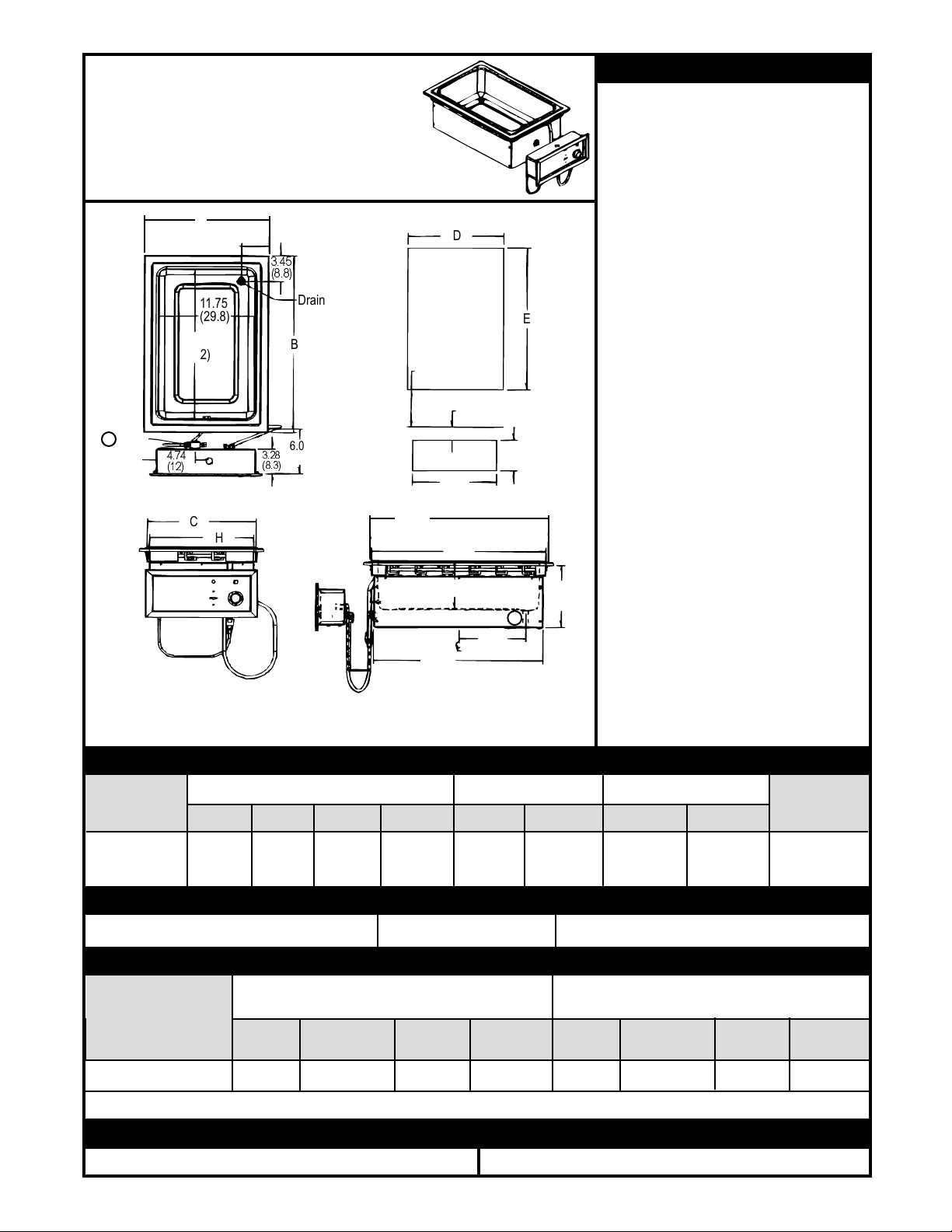
INSTALLATION
APW EZFILL HOT FOOD WELLS
Part Numbers Beginning with WHFW
A
3.42
1
Water
Inlet
4.74
(12)
(8.7)
11.75
(29.8)
19.75
(50.2)
C
H
3.28
(8.3)
3.45
(8.8)
Drain
B
Cut-Out
Front Edge
6.00
(15.2)
21.80
(55.4)
1. Water fill is 3/8 (1.0) tubing connection on left back of left controls.
2. Main drain is ¾ female NPT.
D
Hot Food Well
Cut-Out
6.00 (15.2)
Minimum
From
Counter Edge
2.00 (5.1) Minimum
From Counter Top
G
Control Cut-Out
21.44
(54.4)
6.50 (16.5)
8.27
20.84
(52.9)
(21)
E
F
2
8.28
(21)
1. Follow general installation
instructions on page 3.
2. Make applicable Cut-Out per above
table. Unit is designed for
Note:
installationin stainless steel tops.
Optional wood mounting kit available.
3. Apply putty tape to the underside
perimeter of the well rimouteredge.
4. Apply a 1/4" (.6) bead of silicone
sealant adjacent to the putty tape on
the well flange.
5. Drop well into opening from the top
and push down until entire
parameter of rim is flush with the
counter surface.
6. From below the counter surface
insert an 8" to10"(20to 25 cm) flat tip
screwdriver into the locking ring tab
slots and twist in a clockwise motion
to lock well in place.
7. Trim excess putty and sealant from
around well rim.
8. Mount control to front panel using
hardware. Maintain 4" (10.2)
clearance between well and front
panel.
9. Check nameplate for proper voltage.
Connect power.
10. Connect overflow tube on hot food
well to suitable tubing to handle
212°F water.Run to open drain.
Electrically connect units to
Note:
comply with local and NECcodes.
GENERAL SPECIFICATIONS (APW EZFILL HOT FOOD WELLS)
MODEL
OUTSIDE DIMENSIONS
CUT-OUT CONTROL CUT-OUT
SHIP WT.
ABCHDE F G
SHFWEZ-1
WELL
15.38” 23.44” 13.80” 12.85” 14.25” 22.25” 5.0” 12.5” 12.4 Lbs.
(39.1) (59.5) (35.10) (32.6) (36.2) (56.5) (12.7) (31.8) (10.9 Kg)
OPTIONS
Description: Lever Operated Drain Valve Stock Number: 56360 Drain Manifold: Fabricated to Unit, Required
ELECTRICAL SPECIFICATIONS
ELECTRICAL RATINGS
1200 EA. @ 208V / 1600 EA. @ 240V
ELECTRICAL RATINGS
1600 EA. @ 208V
MODEL
VOLTS WATTS AMPS AMPS VOLTS WATTS AMPS AMPS
(1 Ph) (3 Ph) (1 Ph) (3 Ph)
SHFWEZ-1 WELL 208/240 1200/1600 5.8 / 6.7 N/A 208 1600 7.7 N/A
NOTE: CUT-OUT SIZES ARE DIFFERENT FROM STANDARD APW HOT FOOD WELLS (HFW’S)
OPERATION
1. Follow General Operating Instructions on page 3. 1. Follow General Cleaning Instructions on page 3
CLEANING
6
Page 7
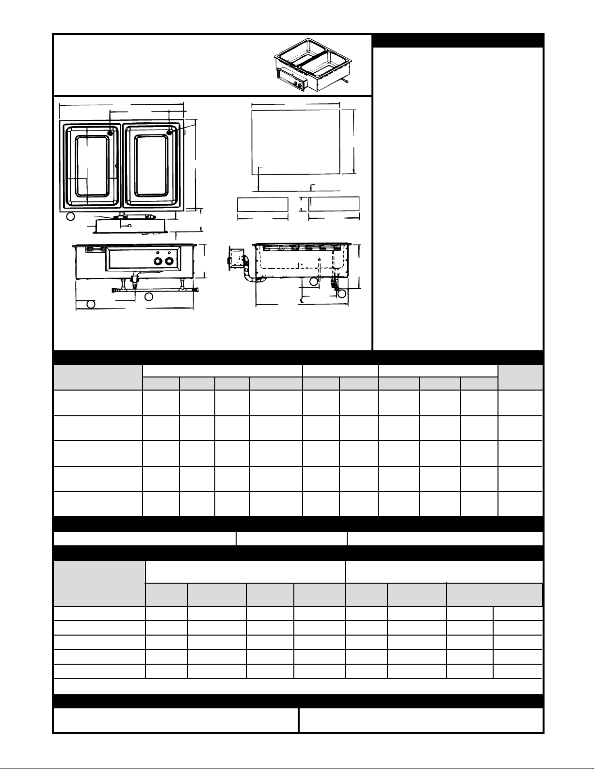
INSTALLATION
APW EZFILL HOT FOOD WELLS
Part Numbers Beginning with WHFW
D
Hot Food Well
Cut-Out
6.0 (15.2) Minimum
From Counter Edge
F
Control Cut-Outs
6.50 (16.5)
4.13
(10.5)
21.88
(55.6)
2
8.27
(21.0)
2.0 (5.1) Minimum
From Counter Top
1
19.75
(50.2)
Water
Inlet
11.74
(29.8)
2
Overflow
5.74
(14.6)
J
A
13.981
(35.51)
C
Manifold
3
3.284
(8.34)
3.434
(8.72)
Drain
B
6.0
(15.2)
(22.0)
Cut-Out
Front Edge
8.65
G
1. Water fill is 3/8 (1.0) tubing connection on left back of left controls.
2. Overflow drain is 1/2” (1.3) OD tube outlet
3. Main drain is ¾ female NPT.
H
3
1. Follow general installation instructions
on page 3.
2. Make applicable Cut-Out per above table.
Note:
Unit isdesignedfor inst allatio ni n
stainless steel tops. Optional wood
mounting kitavailable.
3. Apply putty tape to the underside
perimeter of the well rim outer edge.
4. Apply a 1/4" (.6) bead of silicone sealant
E
adjacent to the putty tape on the well
flange.
5. Drop wellintoopeningfromthetop a n d
push down until entire parameter of rim
is flush with the counter surface.
6. From below the counter surface insert
an 8" to 10" (20 to 25 cm) flat tip
screwdriver into thelocking ring tab slots
and twist in a clockwise motion to lock
well in place.
7. Trim excess putty and sealant from
around well rim.
8. Mount control to front panel using
11.27
(28.6)
hardware. Maintain 4" (10.2) clearance
between well and front panel.
9. Check nameplate for proper voltage.
Connect power.
10. Connect overflow tube on hot food well
to suitabletubing to handle212°F water.
Run to open drain. Electrically
connect units to comply with local and
NEC codes.
Note:
GENERAL SPECIFICATIONS (APW EZFILL HOT FOOD WELLS)
MODEL
OUTSIDE DIMENSIONS
A B C J Overflow D E F G H
CUT-OUT CONTROL CUT-OUT
SHIP WT.
SHFWEZ-2D WELL 29.42” 23.44” 27.79” 13.87” 28.5” 22.5” 5.0” 16.50” N/A 48 Lbs
(74.2) (59.5) (70.6) (35.2) (72.4) (57.2) (12.7) (41.9) (21.8 Kg).
SHFWEZ-3D WELL 43.46” 23.44” 41.83” 27.92” 42.5” 22.5” 5.0” 33.50” 12.50” 68 Lbs
(110.4) (59.5) (106.2) (70.9) (108) (57.2) (12.7) (85.1) (30.8 Kg)
SHFWEZ-4D WELL 57.50” 23.44” 55.87” 27.92” 56.5” 22.5” 5.0” 16.50” N/A 98 Lbs
(146.0) (59.5) (141.9) (70.9) (143.5) (57.2) (12.7) (41.9) (44.4 Kg)
SHFWEZ-5D WELL 71.54” 23.44” 69.92” 41.96” 70.05” 22.5” 5.0” 33.50” N/A 118 Lbs
(181.7) (59.5) (177.6) (106.6) (179.1) (57.2) (12.7) (85.1) (53.5 Kg)
SHFWEZ-6D WELL 85.59” 23.44” 83.96” 41.96” 84.50” 22.5” 5.0” 33.50” N/A 260 Lbs
(217.4) (59.5) (213.2) (106.6) (214.6) (57.2) (12.7) (85.1) (117.9 Kg)
OPTIONS
Description: Lever Operated Drain Valve Stock Number: 56360 Drain Manifold: Fabricated to Unit, Required
ELECTRICAL SPECIFICATIONS
ELECTRICAL RATINGS
1600 EA. @ 208V
MODEL
ELECTRICAL RATINGS
1200 EA. @ 208V / 1600 EA. @ 240V
VOLTS WATTS AMPS AMPS VOLTS WATTS AMPS AMPS
(1 Ph) (3 Ph) (1 Ph) (3 Ph)
SHFWEZ-2D WELL 208/240 2400/3200 12 / 14 10 / 12 208 3200 16 14
SHFWEZ-3D WELL 208/240 3600/4800 18 / 20 10 / 12 208 4800 23 14
SHFWEZ-4D WELL 208/240 4800/6400 24 / 27 16 / 18 208 6400 31 21
SHFWEZ-5D WELL 208/240 6000/8000 29 / 34 20 / 24 208 8000 39 27
SHFWEZ-6D WELL 208/240 7200/9600 35 / 40 20 / 24 208 9600 47 27
NOTE: CUT-OUT SIZES ARE DIFFERENT FROM STANDARD APW HOT FOOD WELLS (HFW’S)
OPERATION
1. Follow General Operating Instructions on page 3. 1. Follow General Cleaning Instructions on page 3
CLEANING
7
Page 8
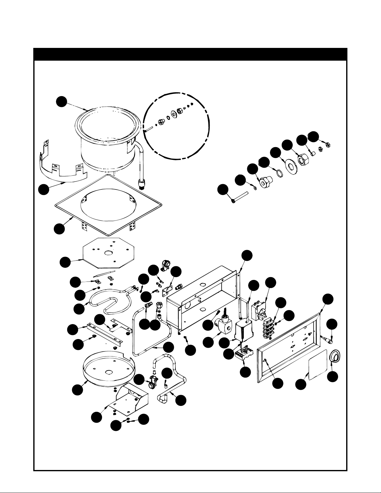
PARTS LIST & EXPLODED VIEW
SM50EZ Round Soup Well Drop-In with EZ Lock P/N EZSM50-7D 208/240V, 500/650W
EXPLODED VIEW SM50EZ
16
32
31
28
27
25
“B”
26
29
45
30
DETAIL “B”
44
17
20
41
22
24
18
21
19
8
23
36
15
37
1
10
13
3
14
2
35
6
7
40
35
34
11
12
43
9
42
33
5
4
39
38
23
24
8
Page 9

PARTS LIST SM50EZ EZ FILL MULTI WELLSPARTS LIST SM50EZ EZ FILL MULTI WELLS
ITEM P/N DESCRIPTION ITEM P/N DESCRIPTIONITEM P/N DESCRIPTION ITEM P/N DESCRIPTION
Washer 1/2-20 SS
1 54561 Control Box W/Assy 12.50 "
1 54561 Control Box W/Assy 12.50 "
2 54503 Bezel Control 12.50"
2 54503 Bezel Control 12.50"
3 56527 Thermostat 36" Capillary
3 56527 Thermostat 36" Capillary
4 56528 Knob, Black
4 56528 Knob, Black
5 63012 Indicator Light (56530)
5 63012 Indicator Light (56530)
6 54577 Adapter, 1/4" Tube To 3/8” Pipe
6 54577 Adapter, 1/4" Tube To 3/8” Pipe
7 54578 Tubing, Copper, 1/4”
7 54578 Tubing, Copper, 1/4”
8 55343 90° Conduit Connector
8 55343 90° Conduit Connector
9 54511 Octal Base Use With 54510
9 54511 Octal Base Use With 54510
10 54524 Bracket, Solenoid Valve
10 54524 Bracket, Solenoid Valve
11 54513 Water Solenoid Valve
11 54513 Water Solenoid Valve
12 54510 Liquid Level Control Octal Base
12 54510 Liquid Level Control Octal Base
XXXX Liquid Level Control Open Board
XXXX Liquid Level Control Open Board
13 54512 Hold Down Strap Use With 54510
13 54512 Hold Down Strap Use With 54510
14 30201 Terminal Block
14 30201 Terminal Block
15 54508 Brass Fitting 1/8 NPT x 1/4 Compression
15 54508 Brass Fitting 1/8 NPT x 1/4 Compression
16 54572 7 Qt. Round Well Pan W/Copper Tube
16 54572 7 Qt. Round Well Pan W/Copper Tube
17 50817 Plate, Heat Diffuser
17 50817 Plate, Heat Diffuser
18 55964 Heating Element 208/240V, 500W/660W
18 55964 Heating Element 208/240V, 500W/660W
19 55696 Bracket, Element Holder
19 55696 Bracket, Element Holder
20 55695 Bracket, Element Holder
20 55695 Bracket, Element Holder
21 89025 10-24 Speed Nut
21 89025 10-24 Speed Nut
22 55992 Bottom Cover
22 55992 Bottom Cover
23 89059 #10 External Lock Washer
23 89059 #10 External Lock Washer
24 89061 Nut, Hex 10-24
24 89061 Nut, Hex 10-24
25 54544 O-Ring For Probe Holder
25 54544 O-Ring For Probe Holder
26 54543 Probe Holder
26 54543 Probe Holder
27 54546
27 54546
28 54549
28 54549
29 54545
29 54545
30 88971
30 88971
31 54548
31 54548
32 89063
32 89063
33 56542
33 56542
34 88961
34 88961
35 89054
35 89054
36 88993
36 88993
37 89073
37 89073
38 51016
38 51016
39 55342
39 55342
40 55340
40 55340
41 89120
41 89120
42 88889
42 88889
43 88977
43 88977
44 55333
44 55333
45 55402
45 55402
56655 Drain Strainer
56655 Drain Strainer
54532 Wire Set Two Well
54532 Wire Set Two Well
54533 Wire Set Three Well
54533 Wire Set Three Well
54534 Wire Set Four Well
54534 Wire Set Four Well
54535 Wire Set Five Well
54535 Wire Set Five Well
54536 Wire Set Six Well
54536 Wire Set Six Well
Washer 1/2-20 SS
Nut, Hex 1/2-20
Nut, Hex 1/2-20
O-ring For Screw
O-ring For Screw
Screw 8-32 X 1-1/2 SS
Screw 8-32 X 1-1/2 SS
Spacer, Probe Holder
Spacer, Probe Holder
Nut, Hex 8-32
Nut, Hex 8-32
Plate, Dial-Wells
Plate, Dial-Wells
10-24 Hex Nut, Green-Ground
10-24 Hex Nut, Green-Ground
6-32 KEPS Nut
6-32 KEPS Nut
10-32 X 3/8 Truss Head Screw
10-32 X 3/8 Truss Head Screw
#8 X 1/2 Sheet Metal Screw
#8 X 1/2 Sheet Metal Screw
Cover, Terminal
Cover, Terminal
3/8" Conduit
3/8" Conduit
Anti-Short Bushing
Anti-Short Bushing
Jiffy Clip
Jiffy Clip
8 X 1/2 AB SMS, Phl Truss
8 X 1/2 AB SMS, Phl Truss
6-32 X 1.0 Slotted Pan Head
6-32 X 1.0 Slotted Pan Head
Wood Mount Kit SM-50-7
Wood Mount Kit SM-50-7
EZ Lock Clip 4 Tab
EZ Lock Clip 4 Tab
HARDWARE NOT SHOWNHARDWARE NOT SHOWN
Heating Element
SM-50 WIRING DIAGRAMS
Indicator Light
Heating Element
Robert Shaw
Thermostat
Indicator Light
Ranco
Thermostat
9
Page 10

PARTS LIST & EXPLODED VIEW
Small Frame Insulated Top Mount EZ Fill Hot Food Wells HFWEZ12D, P/N EZ12D4B-208/240V-500/660W
EXPLODED VIEW HFWEZ-12D
21
23
22
18
DETAIL “C”
DETAIL “D”
16
45
17
8
31
30
“C”
14
15
6
47
4
“D”
48
47
50
48
9
49
50
42
7
41
19
1
38
35
24
37
40
12
20
36
3
34
25
13
33
26
39
5
13
10
43
2
32
27
44
11
28
33
34
46
29
19
51
10
Page 11

PARTS LIST HFWEZ12D EZ FILL MULTI WELLS
ITEM P/N DESCRIPTION ITEM P/N DESCRIPTIONITEM P/N DESCRIPTION ITEM P/N DESCRIPTION
1 54561 ControlBox W/Assy 12.50"
2 55342 3/8" Conduit
3 55340 Anti-short Bushing
4 54578 Tubing, Copper, 1/4
5 88889 8 X 1/2 AB Sms, Phl Truss
6 54508 Brass Fitting 1/8 Npt X 1/4 Compression
7 56406 Wrapper, 1/2 Size Outer
8 54567 1/2 Size Well Pan W/Copper Tube
9 54571 Wrapper Outer End
10 30201 Terminal Block
11 56505 Knob, Black
12 88977 6-32 X 1.0 Slotted Pan Head
13 89054 6-32 KEPS Nut
14 54546 Washer 1/2-20 SS
15 54549 Nut, Hex 1/2-20
16 54543 Probe Holder
17 88971 Screw 8-32 X 1-1/2 SS
18 54548 Spacer, Probe Holder
19 89073 #8 X 1/2 Sheet Metal Screw
20 88993 10-32 X 3/8 Truss Head Screw
21 89063 Nut, Hex 8-32
22 54544 O-ring For Probe Holder
23 54545 O-ring For Screw
24 50817 Plate, Heat Diffuser
25 55964 Heating Element 208/240V, 500W/1660W
26 55695 Bracket, Element Holder
27 55696 Bracket, Element Holder
28 55992 Bottom Cover
29 56404 Bottom Cover
30 56655 Drain Strainer
31 88961
32 89025
33 89059
34 89061
35 55343
36 89120
37 54511
38 54524
39 54513
40 54510
XXXX
41 54512
42 54503
43 56527
44 56536
45 54577
46 56945
47 56412
48 56411
49 55305
50 56402
51 56388
56542 Plate, Dial-Wells
54532 Wire Set Two Well
54533 Wire Set Three Well
54534 Wire Set Four Well
54535 Wire Set Five Well
54536 Wire Set Six Well
10-24 Hex Nut, Green-ground
10-24 Speed Nut
#10 External Lock Washer
Nut, Hex 10-24
90° Conduit Connector
Jiffy Clip
Octal Base Use With 54510
Bracket, Solenoid Valve
WaterSolenoid Valve
Liquid Level Control Octal Base
Liquid Level Control Open Board
Hold Down Strap Use With54510
Bezel Control 12.50"
Thermostat 36" Capillary
Indicator Light (56530)
Adapter,1/4"TubeTo3/8”Pipe
Insulation 12x9x1/2
Insulation 12x9x1/2
Insulation 12x9x1/2
EZ Lock, 4 Tab
EZ Lock 1/2 Warmer
Plate, Hole Cover
HARDWARE NOT SHOWNHARDWARE NOT SHOWN
HFW-12 WIRING DIAGRAM
Thermostat
Indicator Light
Heating Element
11
Page 12

3
PARTS LIST & EXPLODED VIEW
37
27
EXPLODED VIEW HFWEZ-1D
17
32
DETAIL “B”
25
16
35
10
33
34
28
“B”
36
18
31
7
29
3
21
53
19
30
21
19
20
23
5
24
6
9
21
19
1
21
26
23
8
55
2
54
20
11
9
51
50
47
52
4
49
48
40
38
21
45
12
41
24
8
6
19
7
15
43
42
14
39
44
22
13
46
Small Frame Insulated Top Mount EZ Fill Hot Food Wells HFWEZ-1D SHFWEZ-1D P/N EZ1D2B-208V-1600W, SHFWEZ-1D P/N EZ1D4B-208/240V-1200/1600W
12
Page 13

PARTS LIST HFWEZ1D EZ FILL MULTI WELLS
ITEM P/N DESCRIPTION ITEM P/N DESCRIPTIONITEM P/N DESCRIPTION ITEM P/N DESCRIPTION
1 54551 Base
2 54555 Cover, Bottom
3 55308 E-Z Lock, 6 Tab
4 55340 Anti-Short Bushing
5 54554 Wrapper, End
6 54557 Bracket, Wrapper End
7 54556 E-Z Lock, 2 Tab
8 56515 Insulation,20-3/8x8x1/2
9 56516 Insulation,13x8x1/2
10 89063 Nut, Hex 8-32
11 56513 Insulation, 18x12x1
12 30201 Terminal Block
13 56505 Knob, Thermostat
14 88977 6-32 X 1.0 Slotted Pan Head
15 89054 6-32 KEPS Nut
16 54549 Nut, Hex 1/2-20
17 54545 O-Ring For Screw
18 89061 10-24 Hex Nut
19 56521 Rivet, Pop
20 89025 10-24 Speed Nut
21 89073 #8 X 1/2 Sheet Metal Screw
22 88889 8 X 1/2 AB SMS, Phl Truss
23 54552 Wrapper, Side
24 54558 Bracket, Wrapper Side
25 55789 Sealant, Permagum
26 54564 Hole Cover
27 54559 Well Pan W/Assy (w/Copper Tubes)
28 89120 Jiffy Clip
29 56039 Capillary Cover For Thermostats
30 56506 Reflector Pan
31 55441 Heating Element 208/240V,
1200W/1600W
32 54544 O-ring For (Probe Holder)
33 54543 Probe Holder
34 54546 Washer 1/2-20 SS
35 88971 Screw 8-32 X 1-1/2 SS
36 54548 Spacer, Probe Holder
37 56655 Drain Strainer
38 54561 Control Box W/assy 12.50”
39 54511 Octal Base Use With 54510
40 54524 Bracket, Solenoid Valve
41 54513 Water Solenoid Valve
42 54510 Liquid Level Control Octal Base
XXXX Liquid Level Control Open Board
43 54512 Hold Down Strap Use With 54510
44 54503 BezelControl 12.50”
45 54521 Bezel Control 16.50”
46 54529 BezelControl 33.50”
47 56527 Thermostat 36” Capillary
48 56536 Indicator Light (56530)
49 55343 90° Conduit Connector
50 88993 10-32 X 3/8 Truss Hd Screw
51 55342 3/8” Conduit
52 54553 Wrapper, Control End
53 54508 Brass Fitting 1/8 NPT x ¼ Compression
54 54578 Tubing, Copper, 1/4
55 89059 #10 External Lockwasher
56 54577 Adapter, 1/4” Tube To 3/8 Pipe
57 56388 Plate, Hole Cover
HARDWARE NOT SHOWNHARDWARE NOT SHOWN
88961 10-24Hex Nut, Green-Ground
56542 DialPlate
54532 WireSetTwoWell
54533
54534
54535
54536
Wire Set Three Well
Wire Set Four Well
Wire Set Five Well
Wire Set Six Well
HFW-1D WIRING DIAGRAM (THERMOSTATIC CONTROL CONFIGURATION)
Heating Elements
2
4
1
Probe
Common
7
7
8
1
5
2
6
5
4
3
8
9
3
6
10
Indicator Light
13
Thermostat
Page 14

PARTS LIST & EXPLODED VIEW
Small Frame Insulated Top Mount EZ Fill Hot Food Wells HFWEZ-1D
SHFWEZ-1D P/N EZ1D2B-208V-1600W, SHFWEZ-1D P/N EZ1D4B-208/240V-1200/1600W
EXPLODED VIEW SHFWEZ-1D w/SHUT-OFF VALVE
29
43
28
22
33
34
18
46
16
17
19
59
25
21
47
51
51
27
41
20
1
42
54
54
55
38
57
26
60
60
24
24
44
44
11
40
39
11
58
30
4
4
30
48
48
49
8
10
32
32
7
7
6
6
5
53
53
56
56
36
31
9
9
3
12
12
15
2
52
52
13
45
35
14
50
23
Note: When ordering, ALWAYS specify Part #, Model #, Serial #, Voltage & Phase. P/N 70103067 7/05
14
37
Page 15

PARTS LIST SHFWEZ1D w/SHUT-OFF VALVE
Item Item
10
11
12
13
14
1
2
3
4
5
6
7
8
9
P/N
54577
56542
56388
89073
89059
56513
52107
56360
89390
70101018
30201
54508
54510
54511
Description Description
Adapter, 1/4" To 3/8"
Plate, Dial-Wells
Plate, Hole Cover
Screw, #8 X 1/2 Hex Sht Mtl
Washer #10 External Lock
Insulation, 18 X 12 X 1
Nipple, 1/2" NPT X 3" Brass
Valve, Drain 1/2" Threaded
Label, Warranty Against Defects
Tubing, Brass 1/2" X 3" Long
Terminal Block, 600V, 50A
Connector, Male Brass
Control, Liquid Level Single Probe
Base, Liquid Level Control Socket
Quan Quan
1
34
1
35
1
36
32
37
2
38
2
39
1
40
1
41
1
42
1
43
1
44
2
45
1
46
1
47
P/N
88971
88977
88889
88993
89025
89054
89061
89063
89120
56521
54561
54512
70103066
54551
Screw, 8-32x1-1/2 Sl Pn Hd SS
Screw 6-32 X 1 Ph Pan Hd
Screw #8 X 1/2 AB Phl Truss
Screw 10-32x3/8 Trs Hd Phillips Nylk
Nut, Speed 10-24 Pal Zinc
Nut, KEPS 6-32
Nut, Hex 10-24
Nut, Hex 8-32
Clip, Jiffy
Rivet, Pop SS-42-D
W/Ass'y, Control Box
Strap, Hold Down
W/Ass'y, Ez1 Well Pan W/ Overflow
Base
1
2
2
2
16
4
4
2
2
12
1
1
1
1
15
16
17
18
19
20
21
22
23
24
25
26
27
28
29
54513
54543
54544
54545
54546
54548
54549
55308
55340
55343
55441
56039
56506
56515
56516
Valves, Water Solenoid
Holder, Probe
O-Ring, 1/2" ID. X 5/8" OD.
O-Ring, 5/32" ID. X 7/32" OD.
Washer, 1/2-20 S/S
Spacer, Phenolic
Nut, Hex 1/2-20 Plain
E-Z Lock, 6 Tab
Bushing, Anti-Short CCD, #1
Conduit Connector, 90° Flex
Element, 1200/1600W - 208/240V
Cover, Capillary
Plate, Reflector
Insulation, 20-3/8X8X1/2
Insulation, 13X8X1/2
1
48
1
49
1
50
1
51
1
52
1
53
1
54
2
55
2
56
2
57
1
58
1
59
1
60
2
2
54503
54578
54524
54556
55342
54564
54557
54554
54555
54558
54552
55789
70105017
Bezel
Tubing, Copper, 1/4 .032 Wall Refrig
Bracket, Solenoid Valve
E-Z Lock, 2 Tab
Conduit, 1/2"
Plate, Hole Cover
Bracket, Wrapper End
Wrapper, End
Cover, Bottom
Bracket, Wrapper Side
Wrapper, Side
Sealant, GS7500, 6.5 Ft. Lg.
Wrapper, Control End
1
1
1
2
1
1
2
1
1
2
2
1
1
30
31
32
33 56655
56541
60351
56536
Thermostat, Model 375°, 72"cap
Knob, Thermostat 375°F
S/A, Pilot Light Amber
W/Ass'y, Drain Strainer
Note: When ordering, ALWAYS specify Part #, Model #, Serial #, Voltage & Phase. P/N 70103067 7/05
1
1
1
1
15
Page 16

PARTS LIST & EXPLODED VIEW
Small Frame Insulated Top Mount EZ Fill Hot Food Wells HFWEZ-2, -3, -4, -5, -6
EXPLODED VIEW HFWEZ-2, -3, -4, -5, -6
4
8
5
10
3
2
MODEL P/N VOLTS WATTS
HFWEZ-2D EZ2D2B 208 1600
HFWEZ-2D EZ2D4B 208/240 1200/1600
HFWEZ-3D EZ3D2B 208 1600
HFWEZ-3D EZ3D4B 208/240 1200/1600
HFWEZ-4D EZ4D2B 208 1600
HFWEZ-4D EZ4D4B 208/240 1200/1600
HFWEZ-5D EZ5D2B 208 1600
HFWEZ-5D EZ5D4B 208/240 1200/1600
HFWEZ-6D EZ6D2B 208 1600
HFWEZ-6D EZ6D4B 208/240 1200/1600
23
24
6
1
7
9
13
14
16
11
12
15
17
18
19
20
21
22
23
34
35
36
37
38
39
40
41
25
23
31
30
32
42
43
44
45
46
26
33
16
47
50
52
49
48
51
23
28
53
29
24
27
24
23
25
Page 17

PARTS LIST HFWEZ-2, -3, -4, -5, -6 EZ FILL MULTI WELLS
ITEM P/N DESCRIPTION ITEM P/N DESCRIPTIONITEM P/N DESCRIPTION ITEM P/N DESCRIPTION
1 54575 Well Pan W/Assy (w/Copper Tubes)
2 55789 Sealant, Permagum
3 54518 Well Pan W/Assy (w/o Tubes)
4 56655 Drain Strainer
5 88971 Screw 8-32 X 1-1/2 SS
6 54545 O-ring For Screw
7 54543 Probe Holder
8 54544 O-ring For Probe Holder
9 89063 Nut, Hex 8-32
10 54548 Spacer, Probe Holder
11 54546 Washer 1/2-20 SS
12 54549 Nut, Hex 1/2-20
13 57264 Well Brace
14 54577 Adapter, 1/4” Tube To 3/8 Pipe
15 55441 Heating Element 208/240V,
1200W/1600W
54051 HeatingElement 208V/1600W
16 89059 #10 External Lockwasher
17 89120 Jiffy Clip
18 89061 10-24 Hex Nut
19 56039 Capillary Cover For Thermostats
20 56506 Reflector Pan
21 89025 10-24 Speed Nut
22 57252 2 Well Top Plate
57260 3WellTop Plate
57263 4WellTop Plate
57290 5WellTop Plate
57363 6WellTop Plate
23 89073 #8 X 1/2 Sheet Metal Screw
24 55308 E-Z Lock, 6 Tab
25 56050 End Cover
26 56048 Conduit Brace
27 57254 2 Well FrontOrBack Cover
57262 3WellFront Or Back Cover
57266 4WellFront Or Back Cover
57292 5WellFront Or Back Cover
57365 6WellFront Or Back Cover
28 60150 1" X7"X48" Insulation High Temp
29 56388 Hole Cover
30 54526 2 Well BottomCover
54538 3WellBottom Cover
54539 4WellBottom Cover
54540 5WellBottom Cover
54541 6WellBottom Cover
31 54524 Bracket, SolenoidValve
32 54508 Brass Fitting 1/8 NPT X ¼ Compression
33 54504 Control BoxW/assy12.50"
54522 ControlBox W/assy 16.50”
54529 Control Box W/assy 33.50”
34 54512 Hold Down Strap Use With 54510
35 54510 Liquid Level Control Octal Base
XXXX Liquid Level Control Open Board
36 88977 6-32 X 1.0 Slotted Pan Head
37 54511 Octal BaseUseWith 54510
38 54503 Bezel Control 12.50”
54521 Bezel Control 16.50"
54529 BezelControl 33.50”
39 88889 8 X 1/2 AB SMS, Phl Truss
40 56536 Indicator Light (56530)
41 56505 Knob, Thermostat
42 89054 6-32 KEPS Nut
43 54513 Water Solenoid Valve
44 30201 Terminal Block
45 56540 Thermostat 72" Capillary
46 56527 Thermostat 36" Capillary
47 55099 3/4" Conduit 24" Long
48 55058 90° Conduit Connector
49 88993 10-32 X 3/8 Truss Head Screw
50 55059 Anti-Short Bushing
51 87822 Washer Reducing1X3/4
52 89184 7/8" Hole Bushing
53 57258 2 Well DrainManifold
57273 3WellDrain Manifold
57267 4WellDrain Manifold
57293 5WellDrain Manifold
57366 6WellDrain Manifold
HARDWARE NOT SHOWN
88961 10-24 Hex Nut, Green-Ground
54578 Tubing, Copper
56542 Dial Plate
54532 Wire Set Two Well
54533 Wire Set Three Well
54534 Wire Set Four Well
54535 Wire Set Five Well
54536 Wire Set Six Well
17
Page 18

Small Frame Insulated Top Mount EZ Fill Hot Food Wells SHFWEZ-2D, -3D, -4D, -5D, -6D
EXPLODED VIEW SHFWEZ-2D, 3D, 4D, 5D, 6D w/SHUT-OFF VALVE
5 Well Model Shown
(SHFWEZ-5D)
10
10
50
50
PARTS LIST & EXPLODED VIEW
5
5
2
2
16
16
37
37
40
40
1
1
29
29
26
26
28
28
36
36
42
42
27
27
54
54
23
23
3
3
7
9
9
11
22
11
12
12
NA
NA
53
49
49
8
53
56
21
55
50
50
10
58
58
57
15
MODEL P/N VOLTS WATTS
SHFWEZ-2D 70109122 208/240 1200/1600
SHFWEZ-3D 70109132 208/240 1200/1600
SHFWEZ-4D 70109142 208/240 1200/1600
SHFWEZ-5D 70109152 208/240 1200/1600
SHFWEZ-6D 70109162 208/240 1200/1600
56
52
52
59
59
14
14
20
35
35
46
19
19
41
41
17
17
20
24
24
18
18
13
56
38
38
32
39
33
51
51
6
6
4
4
31
31
30
30
48
48
34
34
43
43
44
44
25
45
47
Note: When ordering, ALWAYS specify Part #, Model #, Serial #, Voltage & Phase. P/N 70103068 7/05
18
Page 19

PARTS LIST SHFWEZ-2D, -3D, -4D, -5D, -6D w/SHUT-OFF VALVE
Item Item
1
2
3
4
5
6
7
8
9
10
11
12
13
14
15
16
17
18
19
20
21
22
23
24
25
26
27
28
29
30
31
32
33
34
35
36
37
38
P/N
54579
56655
55789
56388
54580
55099
89120
56506
89061
88993
55441
89059
89390
88889
56541
54577
56542
30201
89054
56536
89073
56039
89025
60351
56360
54544
89063
54546
54543
55058
70101018
88977
54524
54578
54508
54549
88971
54510
XXXX
39
40
41
42
43
44
45
46
47
54513
54545
54512
54548
55059
87822
54511
88961
89071
Description Description
W/Ass'y, EZ Fill Well, 600 Pan
W/Ass'y, Drain Strainer
Sealant, Gs7500, 6.5 Ft. Lg.
Plate, Hole Cover
W/Ass'y, 600 Well Pan
Conduit 3/4" Length 24"
Clip, Jiffy
Plate, Reflector
Nut, Hex 10-24
Screw 10-32x3/8 Trs Hd Phillips
Element, 1200/1600W - 208/240V
Washer #10 External Lock
Label, Warranty Against Defects
Screw #8 X 1/2 AB Sms Phl Truss
Thermostat, Model 375°, 72"cap
Adapter, 1/4” Tube to 3/8” Pipe
Plate, Dial-Wells
Terminal Block, 600V, 50A
Nut, KEPS 6-32
S/A, Pilot Light Amber
Screw, #8 X 1/2 Hex Tapit Sht Mtl
Cover, Capillary
Nut, Speed 10-24 Pal Zinc
Knob, Thermostat 375°F
Valve, Drain 1/2" Threaded
O-Ring, 1/2" ID X 5/8" OD
Nut, Hex 8-32
Washer, 1/2-20 S/S
Holder, Probe
Conduit Connector, 90° Flex
Tubing, Brass 1/2" X 3" Long
Screw 6-32 X 1 Ph Pan Hd
Bracket, Solenoid Valve
Tubing, Copper, 1/4
.032 Wall Refrig
Connector, Male Brass
Nut, Hex 1/2-20 Plain
Screw, 8-32x1-1/2 Sl Pn Hd SS
Liquid Level Control, Octal Base
Liquid Level Control, Open Board
Valves, Water Solenoid
O-Ring, 5/32" ID X 7/32" OD
Strap, Hold Down
Spacer, Phenolic
Bushing, Antishort, 3/4", #4
Washer, Reducing1X3/4
Base, Liquid Level Control Socket
Nut, Hex 10-24, Green
Washer, #10 Flat
Quan
1
5
5
10
4
1
10
5
20
10
5
10
1
4
5
1
1
1
4
5
70
5
80
5
5
1
2
1
1
2
5
2
1
1
2
1
1
1
1
1
1
1
1
2
2
1
1
1
48
49
50
51
52
53
54
55
56
57
58
59
*60
P/N
57258
57273
57267
57293
57366
57252
57260
57263
57290
57363
57254
57262
57266
57292
57365
54526
54538
54539
54540
54541
56048
56050
57264
55308
60150
54503
54521
54528
54504
54522
54529
89184
54532
54533
54534
54235
54236
2 Well Drain Manifold
3 Well Drain Manifold
4 Well Drain Manifold
5 Well Drain Manifold
6 Well Drain Manifold
2 Well Top Plate
3 Well Top Plate
4 Well Top Plate
5 Well Top Plate
6 Well Top Plate
2 Well Cover, Front And Back
3 Well Cover, Front And Back
4 Well Cover, Front And Back
5 Well Cover, Front And Back
6 Well Cover, Front And Back
2 Well EZ Fill, Bottom Cover
3 Well EZ Fill, Bottom Cover
4 Well EZ Fill, Bottom Cover
5 Well EZ Fill, Bottom Cover
6 Well EZ Fill, Bottom Cover
W/Ass'y, Conduit Brace
Housing, End
Brace, Well Runner
E-Z Lock, 6 Tab
Insulation
Bezel Control 12.50"
Bezel Control 16.50"
Bezel Control 33.50"
Control Box W/Ass'y, 12.50"
Control Box W/Ass'y, 16.50"
Control Box W/Ass'y, 33.50"
Bushing, .875 Heyco 2126
2 Well Wire Set
3 Well Wire Set
4 Well Wire Set
5 Well Wire Set
6 Well Wire Set
*Not Shown
Quan
1
1
1
1
1
1
1
1
1
1
2
2
2
2
2
1
1
1
1
1
2
2
4
6
20
1
1
1
1
1
1
1
1
1
1
1
1
Note: When ordering, ALWAYS specify Part #, Model #, Serial #, Voltage & Phase. P/N 70103068 7/05
19
Page 20

HFWEZ-2, -3, -4, -5. 6 WIRING DIAGRAM (THERMOSTATIC CONTROL CONFIGURATION)
Heating Elements
15
14
21
L1
H1
28
4
5
6
7
8
34
22
29
19
23
H1
L1
33
33
28
22
L1
Indicator
Lights
H1
1
Probe
Common
2
18
13
3
23
17
7
8
1
2
6
5
4
3
16
L1
L2
20
L1
L2
H1
H2
19
26
27
29
Thermostat
Wire Nuts
Heating Elements
14
15
HFW-2
20
13
2
18
3
19
27
21
4
5
6
7
22
19
28
29
8
23
19
30
9
24
19
Indicator
Lights
10
31
11
12
25
19
1
Probe
Common
7
8
1
2
6
5
4
3
16
17
L1
L2
26
Thermostat
24
25
30
31
L1
HFW-3
L2
Single Phase
23
24
25
30
31
29
L1
HFW-4
L2
Single Phase
22
23
24
25
30
31
29
28
L1
HFW-5
L2
Single Phase
21
22
23
24
25
30
31
29
28
27
L1
HFW-6
L2
Single Phase
20
21
22
23
24
25
31
30
29
28
27
26
L1
L2
Single Phase
20
Page 21

Notes:
IMPORTANT FOR FUTURE REFERENCE
Please complete this information and retain this manual for the life of the equipment. For
Warranty Service and/or Parts, this information is required.
Model Number Serial Number Date Purchased
21
Page 22

Notes:
22
Page 23

APW WYOTT EQUIPMENT LIMITED WARRANTY
APW Wyott Foodservice Equipment Company warrants it's equipment against defects in materials and workmanship, subject to the
following conditions:
This warranty applies to the original owner only and is not assignable.
Should any product fail to function in its intended manner under normal use within the limits defined in this warranty,at the option of
APW Wyott such product will be repaired or replaced by APW Wyott or its Authorized Service Agency.APW Wyott will only be
responsible for charges incurred or service performed by its Authorized Service Agencies. The use of other than APW Wyott
Authorized Service Agencies will void this warranty and APW Wyott will not be responsible for such work or any charges associated
with same.TheclosestAPWWyottAuthorized ServiceAgentmustbeused.
This warranty covers products shipped into the 48 contiguous United States, Hawaii, metropolitan areas of Alaska and Canada. There
will benolaborcoverage for equipment located on any island not connected by roadway to the mainland.
Warranty coverage on products used outside the 48 contiguous United States, Hawaii, and metropolitan areas of Alaska and Canada
may vary. Contact the international APWWyott distributor,dealer, or service agency for details.
TimePeriod
One year for parts and one year for labor, effective from the date of purchase by the original owner.The Authorized Service Agency
may, at their option, require proof of purchase. Parts replaced under this warranty are warranted for the un-expired portion of the
original product warranty only.
Exceptions
Inallcases,partscovered by extended warranty will be shipped FOB the factory after the first year.
Portable Carry In Products
Equipment weighing over 70 pounds or permanently installed will be serviced on-site as per the terms of this warranty. Equipment
weighing 70 pounds or under, and which is not permanently installed, i.e. with cord and plug, is considered portable and is subject to
the following warranty handling limitations. If portable equipment fails to operate in its intended manner on the first day of
connection, or use, atAPWWyott's option or itsAuthorizedServiceAgency, it will be serviced on site or replaced.
From day two through the conclusion of this warranty period, portable units must be taken to or sent prepaid to the APW Wyott
Authorized ServiceAgency forin-warranty repairs. No mileage or travel charges are allowed on portable units after the first day of use.
If the customer wants on-site service, they may receive same by paying the travel and mileage charges. Exceptions to this rule: (1)
countertop warmers and cookers,which are covered under the Enhanced Warranty Program, and (2) toasters or rollergrills which have
instoreservice.
Exclusions
The following conditions are not covered by warranty:
If the equipment has been changed, altered, modified or repaired by other than an Authorized Service Agency during or after the
warranty period, then the manufacturer shall not be liable for any damages to any person or to any property,whichmay result from the
use oftheequipment thereafter.
This warranty does not cover services performed at overtime or premium labor rates. Should service be required at times which
normally involve overtime or premium labor rates,theownershallbechargedforthedifferencebetween normal service rates and such
premium rates.APWWyott does not assume any liability for extended delays in replacing or repairing anyitemsbeyonditscontrol.
Inallcases,theuseofotherthanAPWWyottAuthorized OEM Replacement Partswill void this warranty.
This equipment is intended for commercial use only.Warrantyis void if equipment is installed in other than commercial application.
WaterQuality Requirements
Water supply intended for a unit that has in excess of 3.0 grains of hardness per gallon (GPG) must be treated or softened before
being used. Water containing over 3.0 GPG will decrease the efficiency and reduce the operation life of the unit.
Note: Product failure caused by liming or sediment buildup is not covered under warranty.
THE FOREGOING WARRANTY IS IN LIEU OF ANY AND ALL OTHER WARRANTIES EXPRESSED OR IMPLIED
INCLUDING ANY IMPLIED WARRANTY OF MERCHANTABILITY OR FITNESS FOR PARTICULAR PURPOSES
AND CONSTITUTES THE ENTIRE LIABILITY OFAPW WYOTT. IN NO EVENT DOES THE LIMITED WARRANTY
EXTEND BEYOND THE TERMS STATED HEREIN.
*Gas/Electric Cookline:
component parts, except switches and thermostats. (2additionalyearsonpartsonly.No labor on second or third year.)
*BroilerBriquettes,
*Heat Strips:
*GlassWindows, Doors, Seals,Rubber Seals, Light Bulbs:
*Equipment failure relating to improper installation, improper utility connection or supply and problems due to
ventilation.
*Equipment that has not been properly maintained, calibration of controls, adjustments, damage from improper cleaning
and water damage to controls.
*Equipment that has not been used in an appropriate manner, or has been subject to misuse or misapplication, neglect,
abuse, accident, alteration, negligence, damage duringtransit,delivery orinstallation, fire, flood, riot or act ofgod.
*Equipment that has the model number or serial number removed or altered.
Models FD, FDL, FDD, FDDL. Two(2) YearWarranty on element only. No labor second year.
Models GCB, GCRB, GF, GGM, GGT, CHP-H, EF, EG, EHP. Three (3) Year Warranty on all
RockGrates, Cooking Grates, Burner Shields,Fireboxes:
90Day Material Only. No Labor.
90Day Material Only.No Labor.
9/05
23
Page 24

R
Phone: +1
(214) 421-7366
Fax: +1 (214) 565-0976
Toll Free: +1 (800) 527-2100
Website: www.apwwyott.com
E-mail: info@apwwyott.com
APW WYOTT
729 Third Avenue
Dallas, TX 75226
24
 Loading...