

Page 1
R
INSTALLATION
AND
OPERATING
INSTRUCTIONS
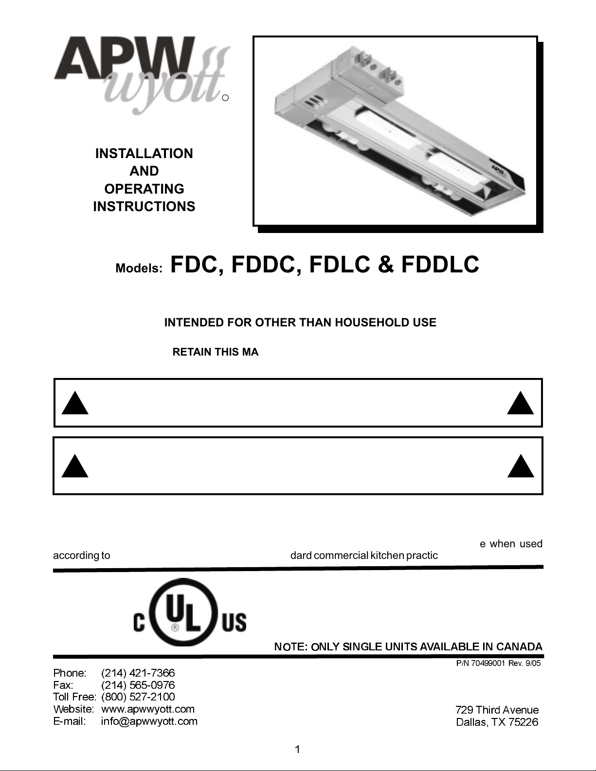
Models: FDC, FDDC, FDLC & FDDLC
CERAMIC OVERHEAD FOODWARMERS
INTENDED FOR OTHER THAN HOUSEHOLD USE
RETAIN THIS MANUAL FOR FUTURE REFERENCE
UNIT MUST BE KEPT CLEAR OF COMBUSTIBLES AT ALL TIMES
FOR YOUR SAFETY: Do not store or use gasoline or other flammable vapors and
liquids in thevicinity of thisor any otherappliance.
WARNING: Improper installation, adjustment, alteration, service or maintenance can
cause property damage, injury or death. Read the Installation, Operating and
Maintenance Instructions thoroughlybefore installing or servicing this equipment.
Initial heating of unit may generate smoke or fumes and must be done in a well ventilated area.
Overexposure to smokeor fumes maycause nausea ordizziness.
This equipment has been engineered to provide you with year-round dependable service when used
according to the instructions in thismanual and standard commercial kitchen practices.
!!
!!
*
NOTE: ONLY SINGLE UNITS AVAILABLE IN CANADA
*
P/N 70499001 Rev. 9/05
Phone:
Fax: (214) 565-0976
Toll Free: (800) 527-2100
Website: www.apwwyott.com
E-mail: info@apwwyott.com
(214) 421-7366
APW WYOTT
729 Third Avenue
Dallas, TX 75226
1
Page 2
TABLE OF CONTENTS
SECTION
1
2
3
4
5
6
7
8
9
ITEM
General Information
Electrical Requirements
Electrical Specifications
Overall Dimensions
Installation
Operation
Cleaning
Troubleshooting
Wiring Diagrams
A. FDC-120V
B. FDC-208/240
C. FDLC-120V
D. FDLC-208/240V
E. FDLC-120V w/Fuse
F. FDDC-120V
G. FDDC-208/240V
H. FDDLC-120V
I. FDDLC-208/240V
J. FDDLC-208/240 w/Fuse
K. Element Configuration - Chart A
PAGE
2
2
3
5
6
6
6
6
7
7
7
8
8
9
9
10
10
11
11
12
10
11
Parts List & Exploded View
Warranty
13
16
1. GENERAL INFORMATION
A. APW Wyott Overhead Foodwarmers are constructedfrom high quality stainless steel and available
in lengths from 18 to 72. Utilizing a ceramic heating element with a reflector, these units give
uniformheat over the entire holding surface.
2. ELECTRICAL REQUIREMENTS
A. Singlephase operation at120, 208, and 240 volts.
B. Field-wired units provided with ½ conduit knockout and terminal blocks easily accessed through
control box access plate. For supply connections, use minimum no. 14 AWG copper wires suitable
forat least 90°C.
2
Page 3
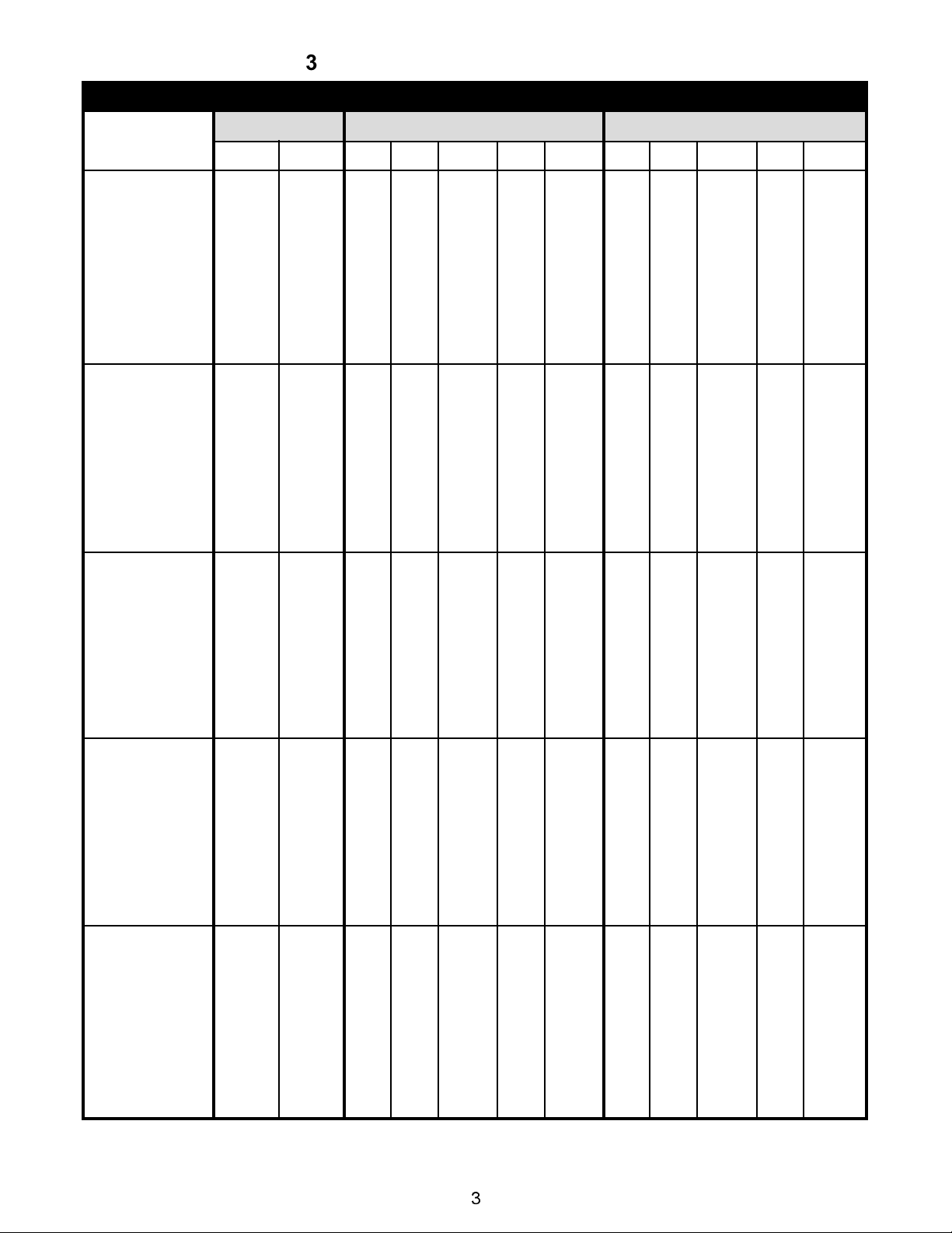
3. ELECTRICAL SPECIFICATIONS
STANDARD CERAMIC OVERHEADS ROCKER SWITCH CONTROL
MODEL
FDC-18
FDC-18
FDLC-18
FDLC-18
FDDC-18
FDDC-18
FDDLC-18
FDDLC-18
FDC-24
FDC-24
FDLC-24
FDLC-24
FDDC-24
FDDC-24
FDDLC-24
FDDLC-24
FDC-30
FDC-30
FDLC-30
FDLC-30
FDDC-30
FDDC-30
FDDLC-30
FDDLC-30
FDC-36
FDC-36
FDLC-36
FDLC-36
FDDC-36
FDDC-36
FDDLC-36
FDDLC-36
FDC-42
FDC-42
FDLC-42
FDLC-42
FDDC-42
FDDC-42
FDDLC-42
FDDLC-42
CIR-1
500
700
580
780
500
700
500
700
700
800
780
880
700
800
700
800
850
1150
930
1230
850
1150
850
1150
1000
1350
1160
1510
1000
1350
1000
1350
1200
1500
1360
1660
1200
1500
1200
1500
WATTS
CIR-2
~
~
~
~
500
700
580
780
~
~
~
~
700
800
780
880
~
~
~
~
850
1150
930
1230
~
~
~
~
1000
1350
1160
1510
~
~
~
~
1200
1500
1360
1660
VOLTS - RATINGS CIR-1
120
4.2
5.8
4.8
6.5
4.2
5.8
4.2
5.8
5.8
6.7
6.5
7.3
5.8
6.7
5.8
6.7
7.1
9.6
7.8
10.3
7.1
9.6
7.1
9.6
8.3
11. 3
9.7
12.6
8.3
11. 3
8.3
11. 3
10.0
12.5
11. 3
13.8
10.0
12.5
10.0
12.5
208
2.4
3.4
~
~
2.4
3.4
2.4
3.4
3.4
3.8
~
~
3.4
3.8
3.4
3.8
4.1
5.5
~
~
4.1
5.5
4.1
5.5
4.8
6.5
~
~
4.8
6.5
4.8
6.5
5.8
7.2
~
~
5.8
7.2
5.8
7.2
120/208
~
~
3.1
4.0
~
~
~
~
~
~
4.0
4.5
~
~
~
~
~
~
4.8
6.2
~
~
~
~
~
6.1
7.8
~
~
~
~
~
~
7.1
8.5
~
~
~
~
240
2.1
2.9
~
~
2.1
2.9
2.1
2.9
2.9
3.3
~
~
2.9
3.3
2.9
3.3
3.5
4.8
~
~
3.5
4.8
3.5
4.8
4.2
5.6
~
~
4.2
5.6
4.2
5.6
5.0
6.3
~
~
5.0
6.3
5.0
6.3
120/240
~
~
2.8
3.6
~
~
~
~
~
~
3.6
4.0
~
~
~
~
~
~
4.2
5.5
~
~
~
~
~
~
5.5
7.0
~
~
~
~
~
~
6.3
7.6
~
~
~
~
VOLTS - RATINGS CIR-2
120
~
~
~
~
4.2
5.8
4.8
6.5
~
~
~
~
5.8
6.7
6.5
7.3
~
~
~
~
7.1
9.6
7.8
10.3
~
~
~
~
8.3
11. 3
9.7
12.6
~
~
~
~
10.0
12.5
11. 3
13.8
208
~
~
~
~
2.4
3.4
~
~
~
~
~
~
3.4
3.8
~
~
~
~
~
~
4.1
5.5
~
~
~
~
~
~
4.8
6.5
~
~
~
~
~
~
5.8
7.2
~
~
120/208
~
~
~
~
~
~
3.1
4.0
~
~
~
~
~
~
4.0
4.5
~
~
~
~
~
~
4.8
6.2
~
~
~
~
~
~
6.1
7.8
~
~
~
~
~
~
7.1
8.5
240
~
~
~
~
2.1
2.9
~
~
~
~
~
~
2.9
3.3
~
~
~
~
~
~
3.5
4.8
~
~
~
~
~
~
4.2
5.6
~
~
~
~
~
~
5.0
6.3
~
~
120/240
~
~
~
~
~
~
2.8
3.6
~
~
~
~
~
~
3.6
4.0
~
~
~
~
~
~
4.2
5.5
~
~
~
~
~
~
5.5
7.0
~
~
~
~
~
~
6.3
7.6
3
Page 4
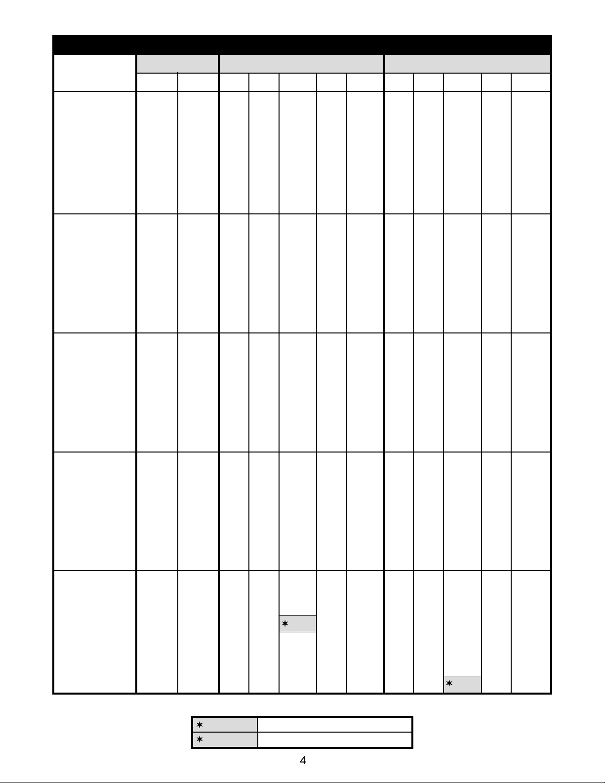
STANDARD CERAMIC OVERHEADS ROCKER SWITCH CONTROL
MODEL
FDC-48
FDC-48
FDLC-48
FDLC-48
FDDC-48
FDDC-48
FDDLC-48
FDDLC-48
FDC-54
FDC-54
FDLC-54
FDLC-54
FDDC-54
FDDC-54
FDDLC-54
FDDLC-54
FDC-60
FDC-60
FDLC-60
FDLC-60
FDDC-60
FDDC-60
FDDLC-60
FDDLC-60
FDC-66
FDC-66
FDLC-66
FDLC-66
FDDC-66
FDDC-66
FDDLC-66
FDDLC-66
FDC-72
FDC-72
FDLC-72
FDLC-72
FDDC-72
FDDC-72
FDDLC-72
FDDLC-72
CIR-1
1500
2000
1660
2160
1500
2000
1500
2000
1500
2200
1660
2360
1500
2200
1500
2200
2000
2700
2240
2940
2000
2700
2000
2700
2000
2700
2240
2940
2000
2700
2000
2700
2000
3000
2240
3240
2000
3000
2000
3000
WATTS
CIR-2
~
~
~
~
1500
2000
1660
2160
~
~
~
~
1500
2200
1660
2360
~
~
~
~
2000
2700
2240
2940
~
~
~
~
2000
2700
2240
2940
~
~
~
~
2000
3000
2240
3240
VOLTS - RATINGS CIR-1
120
12.5
~
13.8
~
12.5
~
12.5
~
~
~
~
~
~
~
~
~
~
~
~
~
~
~
~
~
~
~
~
~
~
~
~
~
~
~
~
~
~
~
~
~
208
7.2
9.6
~
~
7.2
9.6
7.2
9.6
7.2
10.6
~
~
7.2
10.6
7.2
10.58
9.6
13.0
~
~
9.6
13.0
9.6
12.98
9.6
13.0
~
~
9.6
13.0
9.6
12.98
9.6
14.4
~
~
9.6
14.4
9.6
14.42
120/208
~
~
8.5
10.9
~
~
~
~
~
~
8.5
11. 9
~
~
~
~
~
~
11. 6
15.0
~
~
~
~
~
~
11. 6
15.0
~
~
~
~
~
~
11. 6
16.4
~
~
~
~
240
6.3
8.3
~
~
6.3
8.3
6.3
8.3
6.3
9.2
~
~
6.3
9.2
6.3
9.2
8.3
11. 3
~
~
8.3
11. 3
8.3
11. 3
8.3
11. 3
~
~
8.3
11. 3
8.3
11. 3
8.3
12.5
~
~
8.3
12.5
8.3
12.5
120/240
~
~
7.6
9.7
~
~
~
~
~
~
7.6
10.5
~
~
~
~
~
~
10.3
13.3
~
~
~
~
~
~
10.3
13.3
~
~
~
~
~
~
10.3
14.5
~
~
~
~
VOLTS - RATINGS CIR-2
120
~
~
~
~
12.5
~
13.8
~
~
~
~
~
~
~
~
~
~
~
~
~
~
~
~
~
~
~
~
~
~
~
~
~
~
~
~
~
~
~
~
~
208
~
~
~
~
7.2
9.6
~
~
~
~
~
~
7.2
10.6
~
~
~
~
~
~
9.6
13.0
~
~
~
~
~
~
9.6
13.0
~
~
~
~
~
~
9.6
14.4
~
~
120/208
~
~
~
~
~
~
8.5
10.9
~
~
~
~
~
~
8.5
11. 6
~
~
~
~
~
~
11. 6
15.0
~
~
~
~
~
~
11. 6
15.0
~
~
~
~
~
~
11. 6
16.4
240
~
~
~
~
6.3
8.3
~
~
~
~
~
~
6.3
9.2
~
~
~
~
~
~
8.3
11. 3
~
~
~
~
~
~
8.3
11. 3
~
~
~
~
~
~
8.3
12.5
~
~
120/240
~
~
~
~
~
~
7.6
9.7
~
~
~
~
7.6
10.5
~
~
~
~
~
~
10.3
13.3
~
~
~
~
~
~
10.3
13.3
~
~
~
~
~
~
10.3
14.5
REQUIRES 3 AMP FUSE
REQUIRES 30 AMP CIRCUIT
4
Page 5
NOTE: TO AVOID BURNING OR CHARRING OF MATERIALS IN THE SURFACE
BELOW THE FOODWARMER USE ONLY ABOVE AN ALL-METAL STRUCTURE
SUCHASATABLE OR COUNTERTOP. SEE MINIMUM CLEARANCE CHARTABOVE.
REMOTE SWITCHES ARE RECOMMENDED FOR UNDER SHELF MOUNTING.
LONGER SWITCH LIFE WILL RESULT FROM COOLER SWITCH MOUNTING
LOCATIONS.
!!
WARNING:
INSTRUCTIONS IN THIS MANUAL COULD RESULT IN SERIOUS INJURY OR
!
DEATH.
ElectricalGround is requiredon this appliance.
Do not modify the power supply cord plug. If it does not fit into the outlet, have
theproper outlet installedby a qualifiedelectrician
Donot use an extensioncord with thisappliance.
Check with a qualified electrician if you are unsure as to whether the appliance
is properly grounded.
ELECTRICAL SHOCK HAZARD. FAILURE TO FOLLOW THE
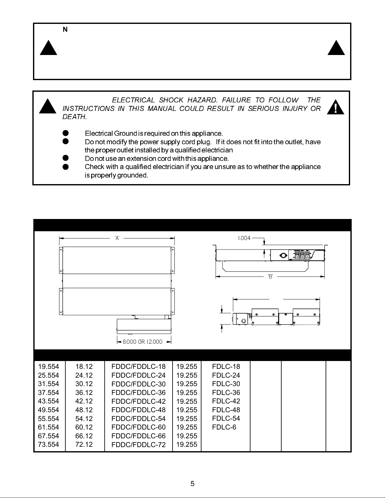
4. OVERALL DIMENSIONS
FDC / FDLC / FDDC / FDDLC MODELS
'A'
1.004
'B'
!
A”
19.554
25.554
31.554
37.554
43.554
49.554
55.554
61.554
67.554
73.554
B”
18.12
24.12
30.12
36.12
42.12
48.12
54.12
60.12
66.12
72.12
O
8.000 R 1 2.000
MODEL
FDDC/FDDLC-18
FDDC/FDDLC-24
FDDC/FDDLC-30
FDDC/FDDLC-36
FDDC/FDDLC-42
FDDC/FDDLC-48
FDDC/FDDLC-54
FDDC/FDDLC-60
FDDC/FDDLC-66
FDDC/FDDLC-72
C”
19.255
19.255
19.255
19.255
19.255
19.255
19.255
19.255
19.255
19.255
2.500
MODEL
FDLC-18
FDLC-24
FDLC-30
FDLC-36
FDLC-42
FDLC-48
FDLC-54
FDLC-60
FDLC-66
FDLC-72
C”
13.255
13.255
13.255
13.255
13.255
13.255
13.255
13.255
13.255
13.255
'C'
2.352
MODEL
FDC-18
FDC-24
FDC-30
FDC-36
FDC-42
FDC-48
FDC-54
FDC-60
FDC-66
FDC-72
C”
10.13
10.13
10.13
10.13
10.13
10.13
10.13
10.13
10.13
10.13
5
Page 6

5. INSTALLATION
A. Alwaysclean equipment thoroughly before first use (See cleaning instructions).
B. Providethe following clearancesaround foodwarmer:
1. Low watt minimum distance to non-combustible surface below: Single = 14, Double = 18.
Highwatt minimum distanceto non-combustiblesurface below: Single =18, Double = 24.
2. Minimumdistanceto non-combustible side (end)walls = 2
3. Minimumdistanceto non-combustible back wall= 2.
4. Minimumdistanceto non-combustible ceiling = 1
5. To avoid damage to overhead or surroundings never mount to combustible ceiling. All
surroundingback, sides and bottom surfaces to be non-combustible.
C. Consult foodwarmer rating label for model designation and correct operating voltage and
amperage.
D. Ceilingmountingbrackets areprovided with each foodwarmer for chain or shelf mounting. Remove
brackets from packaging and screws from ends of foodwarmer to attach brackets. Use four #10
screws or studs with locknuts for shelf mounting. For chain mounting, use #14 jack chain and S
hooks.
E. Remote switches are recommended. Longer switch life will result from cooler switch mounting
locations. Optional stainless steel remote box kits are available. Installation of remote box by
service personnel requires ½ conduit, and no. 14 AWG copper wire suitable for at least 90°C.
Mount remote box to flat surface with two #10 screws or studs with locknuts. All wires marked as
shown on wiring diagram. Whether supplying power to remote or control box remove control box
access plate Ref. exploded view item number 29. Fasten supply wires to terminal block marked t
erminals.To prevent damageto control box componentsre-install access plate item 29 after making
supplyconnections.
F. Optional tubular stands are available for permanently mounting foodwarmers to non-combustible
countertops.
G. Optionalportable legs are available for foodwarmers for use over non-combustible countertops.
6. OPERATION
A. Allfoodservice equipment should be operated by trained personnel.
B. Donot allow your customers to come in contact with any surface labeled CAUTION HOT.
C. Switchon unit. Place precooked product under heat source. Maximum heat coverage equivalent
to unit length.
D. Neverholdfood below 150°F.
WARNING: DO NOT TOUCH CERAMIC ELEMENTS WHILE UNIT IS ON OR
!
COOLING DOWN.
!
7. CLEANING
A. Neverclean any electricalunit by immersingit in water.
B. Neverclean any electricalunit using water jets.
C. Disconnectpowerbefore cleaningor servicing units.
D. Clean unit daily. Use warm, soapy water. Mild cleansers and non-abrasive pads may be used to
removebaked-on food.
8. TROUBLESHOOTING
A. Alwaysask and check:
1. Istheunit connected toa live power source?
2. Checkthecircuit breaker.
3. Ispowerswitch on andlight illuminating?
4. Checktherating label. Is the unitoperating on propervoltage?
B. If the above checks out, and problems still exist, call anAPWWyott authorized service agency.
C. Allserviceshould be performedby anAPW Wyottauthorized serviceagency.
6
Page 7

9. WIRING DIAGRAMS
A.
FDC-120V WIRING DIAGRAM
ELEMENT(S) - SEE ELEMENT CONFIG. CHART A
6
6
FDC-120V
NOTE: WIRE#'S 4, 5, AND 6 - 10GA. 450°C.
WIRE# 1 - 12GA. 105°C .
ALL OTHER - 12GA. 200 OR 250°C.
5
4
FOR REMOTE MODELS
LABEL LEAD WIRES AS SHOWN.
LEADS TO BE 6" FROM HOUSING.
FRONT HEAT-SW
1
4
2
8
A-LN
7
A-L1
5
6
3
2
3
1
GRN
CIR1-LN
CIR1-L1
B.
FDC-208/240V WIRING DIAGRAM
ELEMENT(S) - SEE ELEMENT CONFIG. CHART A
6
6
FDC-208/240V
NOTE: WIRE#'S 4, 5, AND 6 - 10GA. 450°C.
WIRE# 1 - 12GA. 105°C
ALL OTHER - 12GA. 200 OR 250°C.
5
4
FOR REMOTE MODELS
LABEL LEAD WIRES AS SHOWN.
LEADS TO BE 6" FROM HOUSING.
FRONT HEAT-SW
1
4
2
7
A-L1
A-L2
8
5
6
3
2
3
1
GRN
CIR1-L1
CIR1-L2
7
Page 8

C.
FDLC-120V WIRING DIAGRAM
TWO LAMPHOLDERSONE LAMPHOLDER
18,24,30 MODELS 60,66,72 MODELS
36,42,48,54 MODELS
THREE LA MP HOLDERS
FOR REMOTE MODELS
LABEL LEAD WIRES AS SHOWN.
LEADS TO BE 6" FROM HOU SING.
B-L1
D.
13
13
13
13
ELEMENT(S) - SEE ELEMENT CONFIG. CHART A
6
6
5
4
FDLC-120V
NOTE: WIRE#'S 4, 5, AND 6 - 10GA. 450°C.
WIRE# 1 - 12GA. 105°C
ALL OTHER - 12GA. 250°C.
FDLC-208/240V WIRING DIAGRAM
11
12
LIGHT-SW
9
B-LN
10
8
A-LN
7
A-L1
FRONT HEAT-SW
1
4
2
5
3
6
2
3
1
GRN
CIR1-L1
CIR1-LN
TWO LAMPHOLDERSONE L AMPHOLDER
TWO LAMPHOLDERSONE L AMPHOLDER
18,24, 30 MODELS 60,66, 72 MODELS
18,24, 30 MODELS 60,66, 72 MODELS
36,42, 48,54 MODELS
36,42, 48,54 MODELS
13
13
THREE L AMPHOLDERS
THREE L AMPHOLDERS
13
13
ELEMENT(S) - SEE ELEMENT CONFIG. CHART A
7
7
5
6
FDLC-208/240
NOTE: WIRE#'S 5, 6, AND 7 - 10GA. 450°C.
WIRE# 1 - 12GA. 105°C
ALL OTHER - 12GA. 250°C.
FOR REMOTE MODELS
LABEL L EAD WIRES A S SHOWN.
LEADS T O BE 6" FR OM HOUSING.
B-N
B-N
11
B-L1
B-L1
12
8
A-L1
A-L1
9
A-L2
A-L2
LIGHT-SW
FRONT HEAT-SW
FRONT HEAT-SW
1
4
1
4
2
5
2
5
6
6
3
3
10
2
3 4
1
GRN
CIR1-L1
CIR1-N
CIR1-L2
8
Page 9

E.
18,24, 30 MODELS 60,66, 72 MODELS
18,24, 30 MODELS 60,66, 72 MODELS
FDLC-208V w/FUSE WIRING DIAGRAM
TWO LAMPHOLDERSONE L AMPHOLDER
TWO LAMPHOLDERSONE L AMPHOLDER
36,42, 48,54 MODELS
36,42, 48,54 MODELS
THREE L AMPHOLDERS
THREE L AMPHOLDERS
B-N
B-N
FOR REMOTE MODELS
LABEL L EAD WIRES A S SHOWN.
LEADS T O BE 6" FR OM HOUSING.
14
FUSE
F.
13
13
13
13
ELEMENT(S) - SEE ELEMENT CONFIG. CHART A
7
7
5
6
FDLC-208V W/FUSE
NOTE: WIRE#'S 5, 6, AND 7 - 10GA. 450°C.
WIRE# 1 - 12GA. 105°C
ALL OTHER - 12GA. 250°C.
FDDC-120V WIRING DIAGRAM
11
B-L1
12
B-L1
8
A-L1
A-L1
9
A-L2
A-L2
LIGHT-SW
FRONT HEAT-SW
FRONT HEAT-SW
1
4
1
4
2
5
2
5
6
6
3
3
10
2
3 4
1
GRN
CIR1-L1
CIR1-N
CIR1-L2
ELEMENT(S) - SEE ELEMENT CONFIG. CHART A
14
14
ELEMENT(S) - SEE ELEMENT CONFIG. CHART A
14
14
FDDC-120V
NOTE: WIRE#'S 8, 9, 10, 11, AND 14 - 10GA. 450°C
WIRE# 1 - 12 GA. 105°C
ALL OTHER - 12GA. 250°C.
FOR REMOTE MODELS
LABEL LEAD WIRES AS SHOWN.
LEADS TO BE 6" FROM HOUSING.
BACK HEAT-SW
1
9
7
B-L1
13
11
B-L2
4
5
2
6
3
FRONT HEAT-SW
4
8
6
A-L1
12
10
A-L2
1
5
2
6
3
2
3
1
4 5
GRN
CIR1-L1
CIR2-L1
CIR1-LN
CIR2-LN
9
Page 10

G.
FDDC-208/240V WIRING DIAGRAM
ELEMENT(S) - SEE ELEMENT CONFIG. CHART A
10
10
ELEMENT(S) - SEE ELEMENT CONFIG. CHART A
10
10
FDDC-208/240V
NOTE: WIRE#'S 6, 7, 8, 9, AND 10 - 10GA. 450°C
WIRE# 1 - 12GA. 105°C
ALL OTHER - 12GA. 250°C.
FOR REMOTE MODELS
LABEL LEAD WIRES AS SHOWN.
LEADS TO BE 6" FROM HOUSING.
BACK HEAT-SW
1
13
8
9
B-L1
14
B-L2
4
2
5
3
6
FRONT HEAT-SW
1
11
6
7
A-L1
12
A-L2
4
2
5
3
6
2
3
1
4 5
GRN
CIR1-L1
CIR1-L2
CIR2-L1
CIR2-L2
H.
FDDLC-120V WIRING DIAGRAM
ELEMENT(S) - SEE ELEMENT CONFIG. CHART
10
10
TWO LAMPHOLDERSONE LAMPHOL DER
18,24,30 MODELS 60,66,72 MODELS
36,42,48,54 MODELS
19
19
THREE LA MPHOLDERS
19
19
ELEMENT(S) - SEE ELEMENT CONFIG. CHART
10
10
FDDLC-120V
NOTE: WIRE#'S 6, 7, 8, 9, AND 10 - 10GA. 450°C
WIRE# 1 - 12GA. 105°C
ALL OTHER - 12GA. 250°C.
8
9
6
7
13
14
16
15
11
12
B-LN
B-L1
C-L1
A-LN
A-L1
FOR REMOTE MODELS
LABEL LEAD WIRES AS SHOWN.
LEADS TO BE 6" FROM HOU SING.
BACK HEAT-SW
1
4
2
5
3
6
18
LIGHT-SW
FRONT HEAT-SW
1
4
2
5
3
6
1
GRN
17
2
3
4 5
CIR1-L1
CIR2-L1
CIR1-LN
CIR2-LN
10
Page 11

I.
FDDLC-208/240V WIRING DIAGRAM
ELEMENT(S) - SEE ELEMENT CONFIG. CHART
11
11
TWO LAMPHOL DERSONE LAMPHOLDER
18,24,30 MODELS 60,66,72 MODELS
36,42,48,54 MODELS
19
19
THREE LA MPHOLDERS
19
19
9
10
ELEMENT(S) - SEE ELEMENT CONFIG. CHART
11
11
7
8
FDDLC-208/240V
NOTE: WIRE#'S 7, 8, 9, 10, AND 11 - 10GA. 450°C
WIRE# 1 - 12GA. 105°C
ALL OTHER - 12GA. 250°C.
14
15
17
16
12
13
B-L1
B-L2
C-LN
C-L1
A-L1
A-L2
FOR REMOTE MODELS
LABEL LEA D WIRES AS S HOWN.
LEADS TO BE 6" FROM HOUSING.
BACK HEAT-SW
1
4
2
5
6
3
LIGHT-SW
FRONT HEAT-SW
1
4
2
5
3
6
1
GRN
18
2
3
4 5 6
CIR1-L1
CIR2-L1
CIR1-L2
CIR2-L2
CIR2-LN
J.
FDDLC-208/240V w/FUSE WIRING DIAGRAM
ELEMENT(S) - SEE ELEMENT CONFIG. CHART
11
11
TWO LAMPHOLDERSONE LAMPHOLDER
18,24,30 MODELS 60,66,72 MODELS
36,42,48,54 MODELS
19
19
THREE LA MPHOLDERS
19
19
ELEMENT(S) - SEE ELEMENT CONFIG. CHART
11
11
FDDLC-208V W/FUSE
NOTE: WIRE#'S 7, 8, 9, 10, AND 11 - 10GA. 450°C
WIRE# 1 - 12GA. 105°C
ALL OTHER - 12GA. 250°C.
FOR REMOTE MODELS
LABEL LEAD WIRES AS SHOWN.
LEADS TO BE 6" FROM HOUSING.
BACK HEAT-SW
1
4
2
14
9
10
15
B-L1
B-L2
C-LN
17
C-L1
16
20
3
5
6
18
FUSE
LIGHT-SW
FRONT HEAT-SW
1
12
7
8
13
A-L1
A-L2
4
2
5
3
6
2
3
1
4 5 6
GRN
CIR1-L1
CIR2-L1
CIR1-L2
CIR2-L2
CIR2-LN
11
Page 12

K.
CHART “A” - ELEMENT CONFIGURATION
FDC-18
FDDC-18
FDC-24
FDDC-24
FDC-30
FDDC-30
FDC-36
FDDC-36
FDC-42
FDDC-42
FDC-48
FDDC-48
FDC-54
FDDC-54
FDC-60
FDDC-60
FDC-66
FDDC-66
FDC-72
FDDC-72
WATTS
500
700
1000
1400
700
800
1400
1600
850
1150
1700
2300
1000
1350
2000
2700
1200
1500
2400
3000
1500
2000
3000
4000
1500
2200
3000
4400
2000
2700
4000
5400
2000
2700
4000
5400
2000
3000
4000
6000
CONFIGURATIONMODEL
(1F) 500
(1H) 500 + (1H) 200
(2F) 500
(2H) 500 + (2H) 200
(1F) 500 + (1H) 200
(1H) 500 + (2H) 150
(2F) 500 + (2H) 200
(2H) 500 + (4H) 150
(1F) 500 + (1H) 200 + (1H) 150
(2H) 500 + (1H) 150
(2F) 500 + (2H) 200 + (2H) 150
(4H) 500 + (2H) 150
(2F) 500
(2H) 500 + (1H) 200 + (1H) 150
(4F) 500
(4H) 500 + (2H) 200 + (2H) 150
(2F) 500 + (1H) 200
(3F) 500
(4F) 500 + (2H) 200
(6F) 500
(3F) 500
(2F) 500 + (2H) 500
(6F) 500
(4F) 500 + (4H) 500
(3F) 500
(4F) 500 + (1H) 200
(6F) 500
(8F) 500 + (2H) 200
(4F) 500
(2F) 500 + (3H) 500 + (1H) 200
(8F) 500
(4F) 500 + (6H) 500 + (2H) 200
(4F) 500
(4F) 500 + (1H) 500 + (1H) 200
(8F) 500
(8F) 500 + (2H) 500 + (2H) 200
(4F) 500
(4F) 500 + (2H) 500
(8F) 500
(8F) 500 + (4H) 500
MODEL
FDLC-18
FDDLC-18
FDLC-24
FDDLC-24
FDLC-30
FDDLC-30
FDLC-36
FDDLC-36
FDLC-42
FDDLC-42
FDLC-48
FDDLC-48
FDLC-54
FDDLC-54
FDLC-60
FDDLC-60
FDLC-66
FDDLC-66
FDLC-72
FDDLC-72
WATTS
580
780
1080
1480
780
880
1480
1680
930
1230
1780
2380
1160
1510
2160
2860
1360
1680
2560
3160
1660
2160
3160
4160
1660
2360
3160
4560
2240
2940
4240
5640
2240
2940
4240
5640
2240
3240
4240
6240
CONFIGURATION
(1F) 500
(1H) 500 + (1H) 200
(2F) 500
(2H) 500 + (2H) 200
(1F) 500 + (1H) 200
(1H) 500 + (2H) 150
(2F) 500 + (2H) 200
(2H) 500 + (4H) 150
(1F) 500 + (1H) 200 + (1H) 150
(2H) 500 + (1H) 150
(2F) 500 + (2H) 200 + (2H) 150
(4H) 500 + (2H) 150
(2F) 500
(2H) 500 + (1H) 200 + (1H) 150
(4F) 500
(4H) 500 + (2H) 200 + (2H) 150
(2F) 500 + (1H) 200
(3F) 500
(4F) 500 + (2H) 200
(6F) 500
(3F) 500
(2F) 500 + (2H) 500
(6F) 500
(4F) 500 + (4H) 500
(3F) 500
(4F) 500 + (1H) 200
(6F) 500
(8F) 500 + (2H) 200
(4F) 500
(2F) 500 + (3H) 500 + (1H) 200
(8F) 500
(4F) 500 + (6H) 500 + (2H) 200
(4F) 500
(4F) 500 + (1H) 500 + (1H) 200
(8F) 500
(8F) 500 + (2H) 500 + (2H) 200
(4F) 500
(4F) 500 + (2H) 500
(8F) 500
(8F) 500 + (4H) 500
Example: FDDLC-24 1480W has 2 full size 500 watt elements and 2 half size 200 watt elements
12
Page 13

10. PARTS LIST & EXPLODED VIEW
FDC / FDLC / FDDC / FDDLC-18 to 72 EXPLODED VIEW
2
9
3
7
6
8
22
4
34
5
20
33
11
11
12
13
14
17
21
10
16
14
13
12
1
16
19
15
26
28
25
29
35
13
23
24
27
18
30
31
32
Page 14

FDC / FDLC / FDDC / FDDLC-18 to 72 PARTS LIST
ITEM P/N DESCRIPTION QUAN
1
70476835
1
70476836
1
70476837
1
70476838
1
70476839
1
70476840
1
70476841
1
70476842
1
70476843
1
70476844
1
70476845
1
70476846
1
70476847
1
70476848
1
70476849
1
70476850
1
70476851
1
70476852
1
70476853
1
70476854
1
70476855
1
70476856
1
70476857
1
70476858
1
70476859
1
70476860
1
70476861
1
70476862
1
70476863
1
70476864
2
76802
3
76211
3
76212
3
76213
3
76214
3
76215
3
76216
3
76217
3
76218
3
76219
3
76220
4
75917
5
75916
6
46877
7
76159
8
76801
9
76865
10
70400146
10
70400147
11
70402028
V=QTY. VARIES S=SINGLE UNIT OR FDC/FDLC D=DOUBLE UNIT OR FDDC/FDDLC
HOUSING W/ASS'Y FD-18
HOUSING W/ASS'Y FD-24
HOUSING W/ASS'Y FD-30
HOUSING W/ASS'Y FD-36
HOUSING W/ASS'Y FD-42
HOUSING W/ASS'Y FD-48
HOUSING W/ASS'Y FD-54
HOUSING W/ASS'Y FD-60
HOUSING W/ASS'Y FD-66
HOUSING W/ASS'Y FD-72
HOUSING W/ASS'Y FDL-18
HOUSING W/ASS'Y FDL-24
HOUSING W/ASS'Y FDL-30
HOUSING W/ASS'Y FDL-36
HOUSING W/ASS'Y FDL-42
HOUSING W/ASS'Y FDL-48
HOUSING W/ASS'Y FDL-54
HOUSING W/ASS'Y FDL-60
HOUSING W/ASS'Y FDL-66
HOUSING W/ASS'Y FDL-72
HOUSING W/ASS'Y
HOUSING W/ASS'Y
HOUSING W/ASS'Y
HOUSING W/ASS'Y
HOUSING W/ASS'Y
HOUSING W/ASS'Y
HOUSING W/ASS'Y
HOUSING W/ASS'Y
HOUSING W/ASS'Y
HOUSING W/ASS'Y
FDD/FDDL-18
FDD/FDDL-24
FDD/FDDL-30
FDD/FDDL-36
FDD/FDDL-42
FDD/FDDL-48
FDD/FDDL-54
FDD/FDDL-60
FDD/FDDL-66
FDD/FDDL-72
COVER SMALL FD
LIGHT SUPPORT W/A DL-18
LIGHT SUPPORT W/A DL-24
LIGHT SUPPORT W/A DL-30
LIGHT SUPPORT W/A DL-36
LIGHT SUPPORT W/A DL-42
LIGHT SUPPORT W/A DL-48
LIGHT SUPPORT W/A DL-54
LIGHT SUPPORT W/A DL-60
LIGHT SUPPORT W/A DL-66
LIGHT SUPPORT W/A DL-72
LAMPHOLDER TWIN
LAMP 40W COATED
660W/250V
#40A15 120V
NIPPLE, 1/8-27 X 3/4 PLATED
COVER, END DL RH
CONTROL
COVER LARGE FD RH CTRL
COVER LARGE FD LH CTRL
INSULATION
INSULATION
INSULATION
OVRHD WRMR 18-72
OVRHD WRMR 18-72
OVRHD WRMR 18-72
S-1 D-2
ITEM P/N DESCRIPTION QUAN
1
1
1
1
1
1
1
1
1
1
1
1
1
1
1
1
1
1
1
1
1
1
1
1
1
1
1
1
1
1
1
1
1
1
1
1
1
1
1
1
V
V
V
1
1
1
V
V
V
12
13
14
15
16
17
17
17
17
17
17
17
17
17
17
17
17
17
17
17
17
17
17
17
17
18
19
20
20
20
21
22
22
22
22
22
22
22
22
22
23
23
24
24
24
24
25
26
27
27
76804
70402029
76803
70476803
76955
70400002
70400009
70400014
70400019
70400024
70400029
70400034
70400039
70400044
70400049
70400054
70400057
70400060
70400063
70400066
70400069
70400072
70400075
70400078
70400081
70444800
89184
95100006
94000028
94400003
95000028
70400084
70400149
70401149
70400085
70400150
70401150
70400083
70400148
70401148
70476314
70476316
70421275
70401275
70411275
70412275
70400005
70400006
70401281
70402281
SUPPORT ELEMENT FD
INSULATION 1/2X6X2-1/2
FD18-72
END PLATE FD
PLATE, FDB AND C END
BRACKET MOUNTING FD
REFLECTOR FD-18 LW
REFLECTOR FD-24 LW
REFLECTOR FD-30 LW
REFLECTOR FD-36 LW
REFLECTOR FD-42 LW
REFLECTOR FD-48 LW
REFLECTOR FD-54 LW
REFLECTOR FD-60 LW
REFLECTOR FD-66 LW
REFLECTOR FD-72 LW
REFLECTOR FD-18 HW
REFLECTOR FD-24 HW
REFLECTOR FD-30 HW
REFLECTOR FD-36 HW
REFLECTOR FD-42 HW
REFLECTOR FD-48 HW
REFLECTOR FD-54 HW
REFLECTOR FD-60 HW
REFLECTOR FD-66 HW
REFLECTOR FD-72 HW
(CERAMIC OVRHD)
(CERAMIC OVRHD)
(CERAMIC OVRHD)
(CERAMIC OVRHD)
(CERAMIC OVRHD)
(CERAMIC OVRHD)
(CERAMIC OVRHD)
(CERAMIC OVRHD)
(CERAMIC OVRHD)
(CERAMIC OVRHD)
(CERAMIC OVRHD)
(CERAMIC OVRHD)
(CERAMIC OVRHD)
(CERAMIC OVRHD)
(CERAMIC OVRHD)
(CERAMIC OVRHD)
(CERAMIC OVRHD)
(CERAMIC OVRHD)
(CERAMIC OVRHD)
(CERAMIC OVRHD)
SWITCH, ROCKER ON-OFF
BUSHING, .875 HEYCO 2126
ELEMENT, CERAMIC, 120V, 500W, FTE
ELEMENT, CERAMIC, 208V, 500W, FTE
ELEMENT, CERAMIC, 240V, 500W, FTE
RETAINER, CERAMIC ELEMENT
ELEMENT, CERAMIC, 120V, 200W, HTE
ELEMENT, CERAMIC, 208V, 200W, HTE
ELEMENT, CERAMIC, 240V, 200W, HTE
ELEMENT, CERAMIC, 120V, 150W, HTE
ELEMENT, CERAMIC, 208V, 150W, HTE
ELEMENT, CERAMIC, 240V, 150W, HTE
ELEMENT, CERAMIC, 120V, 500W, HTE
ELEMENT, CERAMIC, 208V, 500W, HTE
ELEMENT, CERAMIC, 240V, 500W, HTE
REMOTE ENCLOSURE,
REMOTE ENCLOSURE,
W/ASS'Y, REMOTE BOX
W/ASS'Y, REMOTE BOX COVER
W/ASS'Y, REMOTE BOX COVER
W/ASS'Y, REMOTE BOX COVER
SINGLE CONTROL 8"
SINGLE CONTROL 12"
COVER 12" W/FUSE
12"
8"
8"
BRACKET, CONTROL BOX
CONDUIT, ALUMINUM
LABEL, FDDLC CONTROL
LABEL, FDDC CONTROL
N/S=NOT SHOWNFTE=Full Size Ceramic Element HTE=Half Size Ceramic Element
S-2 D-4
S-2 D-4
S-1 D-3
1
S-2 D-4
S-1 D-2
S-1 D-2
S-1 D-2
S-1 D-2
S-1 D-2
S-1 D-2
S-1 D-2
S-1 D-2
S-1 D-2
S-1 D-2
S-1 D-2
S-1 D-2
S-1 D-2
S-1 D-2
S-1 D-2
S-1 D-2
S-1 D-2
S-1 D-2
S-1 D-2
S-1 D-2
V
S-1 D-2
CHART A
CHART A
CHART A
V
CHART A
CHART A
CHART A
CHART A
CHART A
CHART A
CHART A
CHART A
CHART A
1
1
1
1
1
1
1
1
1
1
14
Page 15

FDC / FDLC / FDDC / FDDLC-18 to 72 PARTS LIST
(Continued)
ITEM P/N DESCRIPTION QUAN
70403281
27
70404281
27
55102
28
70400007
29
70401007
29
70444700
30
85602
31
85601
32
33
70401011
34
70400011
70402042
35
35
70402043
V=QTY. VARIES S=SINGLE UNIT OR FDC/FDLC D=DOUBLE UNIT OR FDDC/FDDLC
LABEL, FDLC CONTROL
LABEL, FDC CONTROL
LOCKNUT, 1/2 INCH CONDUIT
PLATE, ACCESS
PLATE, 12 INCH ACCES
BLOCK, TERMINAL,
HOLDER, FUSE
FUSE, BUS SC3 AMP
SHIELD, FTE ELEMENT
SHIELD, HTE ELEMENT
INSULATION, 12”
INSULATION, 8”
3-POLE
CONTROL BOX
CONTROL BOX
ITEM P/N DESCRIPTION QUAN
N/S
1
N/S
1
N/S
2
N/S
1
N/S
1
N/S
V
N/S
1
N/S
1
V
N/S
V
N/S
N/S
1
1
46876
88961
89042
88889
88993
89071
89056
89039
88971
89063
88954
NUT HEX 1/8 -27 PLATED
NUT, HEX 10-24, GREEN
SCREW 8-32 X 1/2 PH SL SS
SCREW #8 X 1/2 AB SMS PHL TRUSS
SCREW 10-32X3/8 TRS HD PHL NYLK
WASHER, #10 FLAT
WASHER #8 INTERNAL LOCK, SS
SCREW, 8-32X5/16 PH PAN SS
SCREW, 8-32x1-1/2 SL PN HD SS
NUT, HEX 8-32
SCREW,8-32X3/16,PH,PH,SS
N/S=NOT SHOWNFTE=Full Size Ceramic Element HTE=Half Size Ceramic Element
V
1
2
V
V
V
V
1
4
V
4
Warranty Procedure
IFYOU NEED WARRANTYSERVICE FOR YOURAPW EQUIPMENT, FOLLOWTHESE STEPS:
1. Securethemodel and serialnumber from thedata tagof your unit.
2. Non-portable equipment- The serviceagency will dispatcha technicianto your location for repairs.
3. Portable equipment - If you request service at your location, you will be responsible for payment of
traveland mileage charges. You cantake the unitto the service agency to avoid thesecharges.
4. For the name of the closest authorized service/parts distributor consult the published list supplied
byAPWWyott or calltheAPW Wyott Service Hot Line, 1-800-733-2203
Notes:
IMPORTANT FOR FUTURE REFERENCE
Please complete this information and retain this manual for the life of the equipment. For
WarrantyServiceand/or Parts, this information is required.
ModelNumber SerialNumber DatePurchased
15
Page 16

11.APW WYOTT EQUIPMENT LIMITED WARRANTY
APW Wyott Foodservice Equipment Company warrants it's equipment against defects in materials and workmanship, subject to the
following conditions:
This warranty applies to the original owner only and is not assignable.
Should any product fail to function in its intended manner under normal use within the limits defined in this warranty, at the option of
APW Wyott such product will be repaired or replaced by APW Wyott or its Authorized Service Agency. APW Wyott will only be
responsible for charges incurred or service performed by its Authorized Service Agencies. The use of other than APW Wyott
Authorized ServiceAgencies will void this warranty and APW Wyott will not be responsible for such work or any charges associated
with same. The closestAPWWyottAuthorized Service Agent must be used.
This warranty covers products shipped into the 48 contiguous United States, Hawaii, metropolitan areas of Alaska and Canada. There
will be no labor coverage for equipment located on any island notconnected by roadway to the mainland.
Warranty coverage on products used outside the 48 contiguous United States, Hawaii, and metropolitan areas of Alaska and Canada
may vary.ContacttheinternationalAPWWyottdistributor,dealer, or service agency for details.
TimePeriod
One year for parts and one year for labor, effective from the date of purchase by the original owner. The Authorized Service Agency
may, at their option, require proof of purchase. Parts replaced under this warranty are warranted for the un-expired portion of the
original product warranty only.
Exceptions
Inall cases, parts covered by extended warranty will be shipped FOB the factory after the first year.
Portable Carry In Products
Equipment weighing over 70 pounds or permanently installed will be serviced on-site as per the terms of this warranty. Equipment
weighing 70 pounds or under, and which is not permanently installed, i.e. with cord and plug, is considered portable and is subject to
the following warranty handling limitations. If portable equipment fails to operate in its intended manner on the first day of
connection, or use, atAPWWyott'soptionoritsAuthorizedServiceAgency, it will be serviced on site or replaced.
From day two through the conclusion of this warranty period, portable units must be taken to or sent prepaid to the APW Wyott
Authorized Service Agency for in-warranty repairs. No mileage or travel charges are allowed on portable units after the first day of use.
If the customer wants on-site service, they may receive same by paying the travel and mileage charges. Exceptions to this rule: (1)
countertop warmers and cookers, which are covered under the Enhanced WarrantyProgram, and (2) toasters or rollergrills which have
instore service.
Exclusions
The following conditions arenot covered by warranty:
If the equipment has been changed, altered, modified or repaired by other than an Authorized Service Agency during or after the
warranty period, then the manufacturer shall not be liable for any damages to any person or to any property, which may result from the
use of the equipment thereafter.
This warranty does not cover services performed at overtime or premium labor rates. Should service be required at times which
normally involve overtime or premium labor rates, the owner shall be charged for the difference between normal service rates and such
premium rates.APWWyottdoesnotassumeanyliability for extended delays in replacing or repairing any items beyond its control.
Inall cases, the use of other than APW WyottAuthorized OEM Replacement Parts will void this warranty.
This equipment is intended forcommercial use only.Warranty isvoid if equipment is installed inother than commercial application.
WaterQualityRequirements
Water supply intended for a unit that has in excess of 3.0 grains of hardness per gallon (GPG) must be treated or softened before
being used. Water containing over 3.0 GPG will decrease the efficiency and reduce the operation life of the unit.
Note: Product failure caused by liming or sediment buildup is not covered under warranty.
THE FOREGOING WARRANTY IS IN LIEU OF ANY AND ALL OTHER WARRANTIES EXPRESSED OR IMPLIED
INCLUDING ANY IMPLIED WARRANTY OF MERCHANTABILITY OR FITNESS FOR PARTICULAR PURPOSES
AND CONSTITUTES THE ENTIRE LIABILITY OF APW WYOTT. IN NO EVENT DOES THE LIMITED WARRANTY
EXTEND BEYOND THE TERMS STATED HEREIN.
*Gas/Electric Cookline:
component parts, except switches and thermostats. (2 additional years on parts only. No labor on second or third year.)
*BroilerBriquettes,
*Heat Strips:
*GlassWindows, Doors, Seals, Rubber Seals, Light Bulbs:
*Equipment failure relating to improper installation, improper utility connection or supply and problems due to
ventilation.
*Equipment that has not been properly maintained, calibration of controls, adjustments, damage from improper cleaning
and water damage to controls.
*Equipment that has not been used in an appropriate manner, or has been subject to misuse or misapplication, neglect,
abuse, accident, alteration, negligence, damage during transit, delivery or installation, fire, flood, riot or act of god.
*Equipment that has the model number or serial number removed or altered.
Models FD, FDL, FDD, FDDL. Two(2)YearWarranty onelement only. No labor second year.
Models GCB, GCRB, GF, GGM, GGT, CHP-H, EF, EG, EHP. Three (3) Year Warranty on all
RockGrates,CookingGrates,BurnerShields,Fireboxes:
90Day Material Only. No Labor.
90DayMaterialOnly.NoLabor.
9/05
16
 Loading...